JP3689986B2 - Digital satellite broadcast receiver and antenna level display method thereof - Google Patents
Digital satellite broadcast receiver and antenna level display method thereof Download PDFInfo
- Publication number
- JP3689986B2 JP3689986B2 JP18863896A JP18863896A JP3689986B2 JP 3689986 B2 JP3689986 B2 JP 3689986B2 JP 18863896 A JP18863896 A JP 18863896A JP 18863896 A JP18863896 A JP 18863896A JP 3689986 B2 JP3689986 B2 JP 3689986B2
- Authority
- JP
- Japan
- Prior art keywords
- signal
- error rate
- output signal
- bit error
- broadcast receiver
- Prior art date
- Legal status (The legal status is an assumption and is not a legal conclusion. Google has not performed a legal analysis and makes no representation as to the accuracy of the status listed.)
- Expired - Fee Related
Links
Images


Classifications
-
- H—ELECTRICITY
- H04—ELECTRIC COMMUNICATION TECHNIQUE
- H04L—TRANSMISSION OF DIGITAL INFORMATION, e.g. TELEGRAPHIC COMMUNICATION
- H04L1/00—Arrangements for detecting or preventing errors in the information received
- H04L1/20—Arrangements for detecting or preventing errors in the information received using signal quality detector
- H04L1/208—Arrangements for detecting or preventing errors in the information received using signal quality detector involving signal re-encoding
-
- H—ELECTRICITY
- H03—ELECTRONIC CIRCUITRY
- H03G—CONTROL OF AMPLIFICATION
- H03G3/00—Gain control in amplifiers or frequency changers
- H03G3/20—Automatic control
- H03G3/30—Automatic control in amplifiers having semiconductor devices
- H03G3/3052—Automatic control in amplifiers having semiconductor devices in bandpass amplifiers (H.F. or I.F.) or in frequency-changers used in a (super)heterodyne receiver
-
- H—ELECTRICITY
- H04—ELECTRIC COMMUNICATION TECHNIQUE
- H04L—TRANSMISSION OF DIGITAL INFORMATION, e.g. TELEGRAPHIC COMMUNICATION
- H04L1/00—Arrangements for detecting or preventing errors in the information received
- H04L1/20—Arrangements for detecting or preventing errors in the information received using signal quality detector
-
- H—ELECTRICITY
- H04—ELECTRIC COMMUNICATION TECHNIQUE
- H04L—TRANSMISSION OF DIGITAL INFORMATION, e.g. TELEGRAPHIC COMMUNICATION
- H04L27/00—Modulated-carrier systems
- H04L27/18—Phase-modulated carrier systems, i.e. using phase-shift keying
- H04L27/22—Demodulator circuits; Receiver circuits
- H04L27/227—Demodulator circuits; Receiver circuits using coherent demodulation
- H04L27/2271—Demodulator circuits; Receiver circuits using coherent demodulation wherein the carrier recovery circuit uses only the demodulated signals
Landscapes
- Engineering & Computer Science (AREA)
- Computer Networks & Wireless Communication (AREA)
- Signal Processing (AREA)
- Quality & Reliability (AREA)
- Circuits Of Receivers In General (AREA)
- Testing, Inspecting, Measuring Of Stereoscopic Televisions And Televisions (AREA)
Description
【0001】
【発明の属する技術分野】
本発明は、デジタル衛星放送受信機及びそのアンテナレベル表示方法に関し、詳細にはリアルタイムで表示できるアンテナレベルの範囲を広げることを可能にする技術に関する。
【0002】
【従来の技術】
衛星放送の電波を的確に受信するためには、衛星放送受信用のアンテナ(以下単にアンテナという)が衛星の方向に正しく向くように調整することが必要である。そして、従来のアナログ衛星放送受信機においては、BSコンバータの出力信号であるBS−IF信号のレベルやBSチューナーのAGC電圧が最大になるようにアンテナの方向を調整していた。
【0003】
【発明が解決しようとする課題】
しかしながら、このようなアナログ衛星放送受信機における調整方法をデジタル衛星放送受信機に適用してもデジタル特有のレベル表示を実現できない。
【0004】
そこで、復調出力のビットエラーレートからアンテナレベルを計算することが考えられるが、復調出力のエラーをカウントしその値を表示するように構成しても、アナログ衛星放送受信機のような広いレンジでの表示は不可能である。
【0005】
【表1】

その理由は、表1に示すように、C/N値が15dB以上になるとエラーが発生するまでの時間が飛躍的に長くなるため、エラーレートをリアルタイムで表示することが極めて困難になるからである。なお、この表の数値は伝送レート42MbpsのQPSK信号を受信した場合の数値である。
【0007】
このため、アンテナの方向を調整する際に15dB以上のC/N値が得られているかどうかの判別が困難となる。直径が40〜50cm程度の小径のアンテナの場合は受信C/N値がもともと低いため14dB程度まで判別できれば足りるが、直径が75cm以上のアンテナの場合には15dB以上の受信C/N値がとれるので、アンテナの調整を高精度に行うことができない。
【0008】
本発明はこのような問題点に鑑みてなされたものであって、デジタル衛星放送受信機において受信C/N値を表示できる範囲を拡げることにより、精度の高いアンテナ調整を可能にすることを目的とする。
【0009】
【課題を解決するための手段】
本発明に係るデジタル衛星放送受信機は、増幅手段と、増幅手段の出力信号からI信号及びQ信号を検波する直交検波手段と、直交検波手段の出力信号をデジタル化するA/D変換手段と、A/D変換手段の出力信号をQPSK復調するQPSK復調手段と、I信号及びQ信号の振幅と参照値とを比較して前記増幅手段のゲインを制御する手段と、QPSK復調手段の出力信号からビットエラーレートを測定する手段と、ビットエラーレートの測定値が小さくなるに従って量子化ノイズが増加する方向に前記参照値を変化させる手段と、ビットエラーレートの測定値に応じたレベルを表示する表示手段とを備えることを特徴とする。
【0010】
また、本発明に係るデジタル衛星放送受信機のアンテナレベル表示方法は、増幅手段と、増幅手段の出力信号からI信号及びQ信号を検波する直交検波手段と、直交検波手段の出力信号をデジタル化するA/D変換手段と、A/D変換手段の出力信号をQPSK復調するQPSK復調手段とを具備するデジタル衛星放送受信機のアンテナレベル表示方法であって、QPSK復調手段の出力信号からビットエラーレートを測定し、このビットエラーレートの測定値が小さくなるに従って量子化ノイズが増加する方向に前記増幅手段のゲインを可変制御すると共に、前記ビットエラーレートの測定値に応じたレベルをアンテナレベルとして表示することを特徴とする。
【0011】
本発明によれば、アンテナレベルを表示する際には、QPSK復調手段の出力信号からビットエラーレートを測定し、このビットエラーレートの測定値に応じて増幅手段のゲインを可変制御すると共に、前記ビットエラーレートの測定値に応じたレベルをアンテナレベルとして表示する。したがって、ビットエラーレートが小さくなると、増幅手段のゲインが小さくなり、量子化ノイズが多くなるので、ビットエラーレートが小さくなる程度が抑制される。この結果、アンテナレベルを表示できる範囲が拡大される。
【0012】
【発明の実施の形態】
以下本発明の実施の形態について図面を参照しながら詳細に説明する。
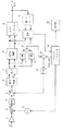
図1は本発明を適用したデジタル衛星放送受信機の要部構成を示すブロック図である。
【0013】
このデジタル衛星放送受信機は、第1中間周波数(以下中間周波数をIFという)信号S1を増幅するアンプ1と、アンプ1の出力を第2IF信号S2に変換する混合器2と、混合器2に与えるローカル信号を発生するローカル発振器3と、混合器2の出力から不要な成分を除去するバンドパスフィルタ4と、バンドパスフィルタ4の出力のレベルを調整するAGCアンプ5と、AGCアンプ5の出力を直交検波してI軸とQ軸のアナログベースバンドデータ(以下I軸のアナログベースバンドデータをI信号、Q軸のアナログベースバンドデータをQ信号という)とする直交検波器6と、このI信号とQ信号をデジタル化するA/D変換器7と、デジタル化されたI信号とQ信号を復調するQPSK復調器8と、復調されたデータのエラーを訂正するエラーコレクション回路9とを備えている。
【0014】
また、このデジタル衛星放送受信機は、デジタル化されたI信号とQ信号の各々の2乗を計算する2乗演算器10,11と、2乗演算器10,11の出力信号の和を計算する加算器12と、加算器12の出力と後述するマイクロコンピュータ14が生成するAGC参照電圧(以下AGC REFという)との差を演算する減算器13と、このデジタル衛星放送受信機全体の制御等を行うマイクロコンピュータ14と、減算器13の出力をアナログ化してAGCアンプ5にゲインコントロール電圧を与えるD/A変換器15とを備えている。
【0015】
さらに、このデジタル衛星放送受信機は、エラーコレクション回路9の出力を再度符号化する再エンコード回路16と、再エンコード回路16の出力とQPSK復調器8の出力とを比較してエラーレートを演算する比較器17と、エラーレートの演算値を基にマイクロコンピュータ14が生成したアンテナレベルを表示する表示器18とを備えている。
【0016】
図1に示したデジタル衛星放送受信機において、衛星から伝送されてきた12GHz帯の信号はアンテナ(図示せず)で受信され、コンバータ(図示せず)により1GHz帯の第1IF信号S1に変換され、アンプ1へ入力される。次に、混合器2において、ユーザーが設定した受信チャンネルに対応する周波数を有するローカル発振器3の出力と掛け合わされ、480MHz帯の第2IF信号S2に周波数変換され、バンドパスフィルタ4により不要な成分が除去される。そして、AGCアンプ5において、D/A変換器15からのAGC REFに従って一定レベルにゲイン制御され、直交検波器6により互いに直交するI信号とQ信号に変換される。このI信号とQ信号はA/D変換器7によりデジタル化され、QPSK復調器8により復調される。そして、この復調出力はエラーコレクション回路9によりエラーが訂正されてビットストリームデータ出力となる。このビットストリームデータ出力は後段のMPEG2デコーダ(図示せず)等へ送られる。
【0017】
また、図1においてA/D変換器7の入力レベルを一定に保ために、このA/D変換器7によりデジタル化されたI信号とQ信号の各々を2乗演算器10,11により2乗した後に加算器12により加算して2乗和を求め、マイクロコンピュータ14から与えられるAGC REFとこの2乗和との差分値を減算器13により計算し、この差分値をD/A変換器15によりアナログ化し、AGCアンプ5にゲインコントロール電圧として与える。この結果、I信号とQ信号の2乗和とAGC REFとが等しくなるように、AGCアンプ5のゲインが自動制御される。
【0018】
さらに、エラーコレクション回路9の出力を再エンコード回路16により再度エラー訂正符号を付加し、エラー訂正前のデータと比較器17において比較することにより、エラーレートを求める。このエラーレートはマイクロコンピュータ14に取り込まれ、アンテナレベルに変換されて、表示器18に与えられる。
【0019】
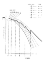
デジタル伝送の場合、アンテナレベルの値はC/N値と考えることが最も信頼性があることで、図2の理論カーブに示すように、ビットエラーレートとC/N値とは一対一に対応付けできる。
【0020】
そして、ビットエラーレートはその性格上、エラーが多い時には瞬時に得られるが、エラーが少ない時には計算するのに時間がかかる。その理由は、伝送レートをR(bps)、ビットエラーレートをEとすると、エラー1個を検出するのに必要な平均時間は1/(R・E)[秒]となるからである。
【0021】
ところが、図1の装置においてアンテナレベルは表示器18の画面に表示されるものであるため、0.5〜1秒以内に表示できないとアンテナの調整に使用できない。表示更新時間を1秒とすると、例えば表1に示した例の場合、C/N値が15〜16dBの時がエラー検出及びアンテナレベル表示の限界になり、それよりもC/N値が高い、つまりエラーレートが低い場合には、エラーフリーとなりエラー検出とアンテナレベル表示ができないことになる。
【0022】
そこで、本実施の形態では、アンテナレベルの表示を行う際に、マイクロコンピュータ14が取り込んだビットエラーレートの値(C/N値に相当)に応じて図2の破線で示すように特性を変化させる。つまり、C/N値が高い場合には等価的にノイズを加え、見かけ上のC/N値を低下させる。具体的には、ビットエラーレートの値が小さくなるに従ってAGC REFのレベルを小さくし、A/D変換器7の入力振幅を適正値より小さくすることで量子化ノイズを増加させ、等価的にC/N値を低くする。図3のアイパターンは、A/D変換器7の入力振幅を小さくすることによりC/N値が小さくなると、量子化ノイズを増えることを示している。
【0023】
図4はビットエラーレートに応じてAGC REFを変化させる様子を示す。この図の▲1▼は理論カーブであり、▲2▼〜▲6▼は理論カーブ▲1▼を右の方向にシフトさせたカーブ、換言すればAGC REFを小さくして等価的にC/N値を小さくしたカーブである。そして、この図に示すように、C/N値が大きくなるに従って選択するカーブを▲2▼→▲3▼→▲4▼→▲5▼→▲6▼にシフトしていく。この処理により、図2に示したように、10-1〜10-7のビットエラーレートに対応するC/N値を理論値である3.4dB〜15.4dBから3.4dB〜18dBに変換している。また、ビットエラーレートが10-7より小さくならないようにしている。この結果、理論カーブと比較すると、C/N値を表示できる範囲が2〜3dB程度拡大することが可能となる。勿論、通常受信状態ではこのような操作は特性の定常劣化につながるので行わず、アンテナレベル表示メニューに従って処理している時のみ行う。
【0024】
このような特性を得るためのプログラムとデータはマイクロコンピュータ14内のメモリ(ROM)に格納されていることはいうまでもない。なお、ここでは説明の便宜上、6個のカーブを用いるものとしたが、実際には多数のカーブを用いることにより、図2の破線で示したような連続的に変化する特性を得ている。このように、本発明はハードウェアの変更を一切必要とせず、ソフトウェアの変更のみで簡単に実現できる。
【0025】
【発明の効果】
以上詳細に説明したように、本発明によればC/N値を表示できる範囲を拡大することかできるので、受信品質の測定レンジを拡大することができる。このため、アンテナの方向調整の精度を向上させることができる。
【0026】
また、本発明はハードウェアの変更を要せず、ソフトウェアの変更のみで実現できる。
【図面の簡単な説明】
【図1】本発明を適用したデジタル衛星放送受信機の要部構成を示すブロック図である。
【図2】ビットエラーレートと受信C/N値との対応関係の理論カーブ及び本発明により変化させたカーブを示す図である。
【図3】A/D変換器の入力振幅を小さくすることによりC/N値が小さくなると、量子化ノイズが増えることを示す図である。
【図4】ビットエラーレートに応じてAGC REFを変化させる様子を示す図である。
【符号の説明】
5…AGCアンプ、6…直交検波器、7…A/D変換器、8…QPSK復調器、9…エラーコレクション回路、10,11…2乗演算器、12…加算器、13…減算器、14…マイクロコンピュータ、15…D/A変換器、16…再エンコード回路、17…比較器、18…表示器[0001]
BACKGROUND OF THE INVENTION
The present invention relates to a digital satellite broadcast receiver and an antenna level display method thereof, and more particularly, to a technique that makes it possible to widen the range of antenna levels that can be displayed in real time.
[0002]
[Prior art]
In order to accurately receive satellite broadcast radio waves, it is necessary to adjust the satellite broadcast receiving antenna (hereinafter simply referred to as the antenna) so that it is correctly oriented in the direction of the satellite. In the conventional analog satellite broadcast receiver, the direction of the antenna is adjusted so that the level of the BS-IF signal that is the output signal of the BS converter and the AGC voltage of the BS tuner are maximized.
[0003]
[Problems to be solved by the invention]
However, even if such an adjustment method in an analog satellite broadcast receiver is applied to a digital satellite broadcast receiver, a digital-specific level display cannot be realized.
[0004]
Therefore, it is conceivable to calculate the antenna level from the bit error rate of the demodulated output, but even if it is configured to count the error of the demodulated output and display the value, it can be used in a wide range like an analog satellite broadcast receiver. Cannot be displayed.
[0005]
[Table 1]
The reason for this is that as shown in Table 1, when the C / N value is 15 dB or more, the time until an error occurs is drastically increased, making it very difficult to display the error rate in real time. is there. The numerical values in this table are values when a QPSK signal having a transmission rate of 42 Mbps is received.
[0007]
For this reason, it is difficult to determine whether a C / N value of 15 dB or more is obtained when adjusting the direction of the antenna. In the case of an antenna with a small diameter of about 40 to 50 cm, the reception C / N value is originally low, so it is sufficient to be able to discriminate up to about 14 dB. However, with an antenna with a diameter of 75 cm or more, a reception C / N value of 15 dB or more can be obtained Therefore, the antenna cannot be adjusted with high accuracy.
[0008]
The present invention has been made in view of such problems, and an object of the present invention is to enable highly accurate antenna adjustment by expanding the range in which a received C / N value can be displayed in a digital satellite broadcast receiver. And
[0009]
[Means for Solving the Problems]
A digital satellite broadcast receiver according to the present invention includes an amplifying unit, a quadrature detecting unit for detecting an I signal and a Q signal from an output signal of the amplifying unit, and an A / D converting unit for digitizing the output signal of the quadrature detecting unit. QPSK demodulating means for QPSK demodulating the output signal of the A / D conversion means, means for controlling the gain of the amplifying means by comparing the amplitudes of the I and Q signals with reference values, and the output signal of the QPSK demodulating means A means for measuring the bit error rate, a means for changing the reference value in a direction in which the quantization noise increases as the measured value of the bit error rate decreases, and a level corresponding to the measured value of the bit error rate. And a display means.
[0010]
Also, the antenna level display method for a digital satellite broadcast receiver according to the present invention comprises an amplifying means, a quadrature detecting means for detecting I and Q signals from the output signal of the amplifying means, and digitizing the output signal of the quadrature detecting means. An antenna level display method for a digital satellite broadcast receiver comprising an A / D conversion means for performing QPSK demodulation for QPSK demodulating an output signal of the A / D conversion means, and a bit error from the output signal of the QPSK demodulation means The rate is measured, and the gain of the amplifying means is variably controlled so that the quantization noise increases as the measured value of the bit error rate decreases, and the level corresponding to the measured value of the bit error rate is set as the antenna level. It is characterized by displaying.
[0011]
According to the present invention, when displaying the antenna level, the bit error rate is measured from the output signal of the QPSK demodulating means, and the gain of the amplifying means is variably controlled in accordance with the measured value of the bit error rate. The level corresponding to the measured bit error rate is displayed as the antenna level. Therefore, when the bit error rate is reduced, the gain of the amplifying unit is reduced and the quantization noise is increased, so that the extent to which the bit error rate is reduced is suppressed. As a result, the range in which the antenna level can be displayed is expanded.
[0012]
DETAILED DESCRIPTION OF THE INVENTION
Hereinafter, embodiments of the present invention will be described in detail with reference to the drawings.
FIG. 1 is a block diagram showing a main configuration of a digital satellite broadcast receiver to which the present invention is applied.
[0013]
This digital satellite broadcast receiver includes an
[0014]
The digital satellite broadcast receiver also calculates the sum of
[0015]
Further, the digital satellite broadcast receiver compares the output of the
[0016]
In the digital satellite broadcast receiver shown in FIG. 1, a 12 GHz band signal transmitted from a satellite is received by an antenna (not shown) and converted into a first IF signal S1 of 1 GHz band by a converter (not shown). , Input to the
[0017]
In FIG. 1, in order to keep the input level of the A /
[0018]
Further, the error correction code is added again to the output of the error correction circuit 9 by the
[0019]
In the case of digital transmission, it is most reliable to consider the antenna level value as a C / N value. As shown in the theoretical curve of FIG. 2, the bit error rate and the C / N value correspond one-to-one. Can be attached.
[0020]
The bit error rate can be obtained instantaneously when there are many errors, but it takes time to calculate when there are few errors. This is because if the transmission rate is R (bps) and the bit error rate is E, the average time required to detect one error is 1 / (R · E) [seconds].
[0021]
However, since the antenna level is displayed on the screen of the
[0022]
Therefore, in this embodiment, when the antenna level is displayed, the characteristic changes as shown by the broken line in FIG. 2 in accordance with the bit error rate value (corresponding to the C / N value) captured by the
[0023]
4 shows AGC according to bit error rate. A state in which REF is changed is shown. (1) in this figure is a theoretical curve, and (2) to (6) are curves obtained by shifting the theoretical curve (1) in the right direction, in other words, AGC. This is a curve in which REF is reduced and the C / N value is equivalently reduced. As shown in this figure, the curve to be selected is shifted from (2) → (3) → (4) → (5) → (6) as the C / N value increases. With this processing, as shown in FIG. 2, the C / N value corresponding to the bit error rate of 10 −1 to 10 −7 is converted from the theoretical value of 3.4 dB to 15.4 dB to 3.4 dB to 18 dB. doing. Further, the bit error rate is prevented from becoming smaller than 10 −7 . As a result, compared with the theoretical curve, the range in which the C / N value can be displayed can be expanded by about 2 to 3 dB. Of course, in the normal reception state, such an operation is not performed because it leads to steady deterioration of characteristics, and is performed only when processing is performed according to the antenna level display menu.
[0024]
Needless to say, the program and data for obtaining such characteristics are stored in a memory (ROM) in the
[0025]
【The invention's effect】
As described above in detail, according to the present invention, the range in which the C / N value can be displayed can be expanded, so that the measurement range of reception quality can be expanded. For this reason, the accuracy of antenna direction adjustment can be improved.
[0026]
Further, the present invention does not require hardware change and can be realized only by software change.
[Brief description of the drawings]
FIG. 1 is a block diagram showing a main configuration of a digital satellite broadcast receiver to which the present invention is applied.
FIG. 2 is a diagram illustrating a theoretical curve of a correspondence relationship between a bit error rate and a received C / N value and a curve changed according to the present invention.
FIG. 3 is a diagram showing that quantization noise increases as the C / N value decreases by decreasing the input amplitude of the A / D converter.
FIG. 4 AGC according to bit error rate It is a figure which shows a mode that REF is changed.
[Explanation of symbols]
DESCRIPTION OF SYMBOLS 5 ... AGC amplifier, 6 ... Quadrature detector, 7 ... A / D converter, 8 ... QPSK demodulator, 9 ... Error correction circuit, 10, 11 ... Square calculator, 12 ... Adder, 13 ... Subtractor, 14 ... Microcomputer, 15 ... D / A converter, 16 ... Re-encoding circuit, 17 ... Comparator, 18 ... Display
Claims (4)
前記増幅手段の出力信号からI信号及びQ信号を検波する直交検波手段と、
前記直交検波手段の出力信号をデジタル化するA/D変換手段と、
前記A/D変換手段の出力信号をQPSK復調するQPSK復調手段と、
前記I信号及びQ信号の振幅と参照値とを比較して前記増幅手段のゲインを制御する手段と、
前記QPSK復調手段の出力信号からビットエラーレートを測定する手段と、
前記ビットエラーレートの測定値が小さくなるに従って量子化ノイズが増加する方向に前記参照値を変化させる手段と、
前記ビットエラーレートの測定値に応じたレベルを表示する表示手段と、
を備えることを特徴とするデジタル衛星放送受信機。Amplifying means;
Quadrature detection means for detecting an I signal and a Q signal from the output signal of the amplification means;
A / D conversion means for digitizing the output signal of the orthogonal detection means;
QPSK demodulation means for QPSK demodulating the output signal of the A / D conversion means;
Means for comparing the amplitudes of the I and Q signals and a reference value to control the gain of the amplification means;
Means for measuring a bit error rate from an output signal of the QPSK demodulation means;
Means for changing the reference value in a direction in which quantization noise increases as the measured value of the bit error rate decreases ;
Display means for displaying a level corresponding to the measured value of the bit error rate;
A digital satellite broadcast receiver comprising:
前記QPSK復調手段の出力信号からビットエラーレートを測定し、該ビットエラーレートの測定値が小さくなるに従って量子化ノイズが増加する方向に前記増幅手段のゲインを可変制御すると共に、前記ビットエラーレートの測定値に応じたレベルをアンテナレベルとして表示することを特徴とするデジタル衛星放送受信機のアンテナレベル表示方法。Amplifying means, quadrature detecting means for detecting I and Q signals from the output signal of the amplifying means, A / D converting means for digitizing the output signal of the quadrature detecting means, and output of the A / D converting means An antenna level display method for a digital satellite broadcast receiver comprising QPSK demodulation means for QPSK demodulating a signal,
The bit error rate is measured from the output signal of the QPSK demodulating means, the gain of the amplifying means is variably controlled in a direction in which the quantization noise increases as the measured value of the bit error rate decreases , and the bit error rate An antenna level display method for a digital satellite broadcast receiver, wherein a level corresponding to a measured value is displayed as an antenna level.
Priority Applications (3)
| Application Number | Priority Date | Filing Date | Title |
|---|---|---|---|
| JP18863896A JP3689986B2 (en) | 1996-06-28 | 1996-06-28 | Digital satellite broadcast receiver and antenna level display method thereof |
| US08/874,368 US5898699A (en) | 1996-06-28 | 1997-06-19 | Digital broadcast receiver and signal level display method |
| KR1019970028212A KR100497265B1 (en) | 1996-06-28 | 1997-06-27 | Digital broadcast receiver and signal level display method |
Applications Claiming Priority (1)
| Application Number | Priority Date | Filing Date | Title |
|---|---|---|---|
| JP18863896A JP3689986B2 (en) | 1996-06-28 | 1996-06-28 | Digital satellite broadcast receiver and antenna level display method thereof |
Publications (2)
| Publication Number | Publication Date |
|---|---|
| JPH1023475A JPH1023475A (en) | 1998-01-23 |
| JP3689986B2 true JP3689986B2 (en) | 2005-08-31 |
Family
ID=16227218
Family Applications (1)
| Application Number | Title | Priority Date | Filing Date |
|---|---|---|---|
| JP18863896A Expired - Fee Related JP3689986B2 (en) | 1996-06-28 | 1996-06-28 | Digital satellite broadcast receiver and antenna level display method thereof |
Country Status (3)
| Country | Link |
|---|---|
| US (1) | US5898699A (en) |
| JP (1) | JP3689986B2 (en) |
| KR (1) | KR100497265B1 (en) |
Families Citing this family (18)
| Publication number | Priority date | Publication date | Assignee | Title |
|---|---|---|---|---|
| JPH10276125A (en) * | 1997-03-28 | 1998-10-13 | Matsushita Electric Ind Co Ltd | Mobile radio receiver |
| JP2001013234A (en) * | 1999-07-01 | 2001-01-19 | Alps Electric Co Ltd | Antenna tracking signal generation circuit |
| JP3573663B2 (en) | 1999-09-21 | 2004-10-06 | 松下電器産業株式会社 | Digital broadcast demodulator |
| US6614806B1 (en) * | 2000-01-06 | 2003-09-02 | Motorola Inc. | Method and apparatus for interfering receiver signal overload protection |
| JP2002022787A (en) * | 2000-07-07 | 2002-01-23 | Dx Antenna Co Ltd | C / N ratio measuring device and C / N ratio measuring method |
| GB2371690A (en) * | 2001-01-24 | 2002-07-31 | Mitel Semiconductor Ltd | Gain control of a stage of a tuner in a radio frequency receiver based on a quality of the demodulated signal |
| SE521838C2 (en) * | 2001-02-16 | 2003-12-09 | Nat Semiconductor Corp | Method and apparatus for automatic gain control |
| JP4698905B2 (en) * | 2001-09-25 | 2011-06-08 | クラリオン株式会社 | Digital broadcast receiver having AGC judgment value update function |
| US6982745B2 (en) * | 2001-11-27 | 2006-01-03 | Sony Corporation | Antenna level display device and method, and receiving apparatus |
| JP3832577B2 (en) * | 2002-04-01 | 2006-10-11 | シャープ株式会社 | Digital satellite broadcast receiver |
| US8559559B2 (en) | 2002-06-20 | 2013-10-15 | Qualcomm, Incorporated | Method and apparatus for compensating DC offsets in communication systems |
| US7190741B1 (en) | 2002-10-21 | 2007-03-13 | The United States Of America As Represented By The Administrator Of The National Aeronautics And Space Administration | Real-time signal-to-noise ratio (SNR) estimation for BPSK and QPSK modulation using the active communications channel |
| JP2005064764A (en) * | 2003-08-08 | 2005-03-10 | Alps Electric Co Ltd | Direct conversion tuner |
| WO2008146431A1 (en) * | 2007-05-30 | 2008-12-04 | Mitsubishi Electric Corporation | Digital broadcast receiver |
| JP4506870B2 (en) * | 2008-04-30 | 2010-07-21 | ソニー株式会社 | Receiving apparatus, receiving method, and program |
| KR100962628B1 (en) * | 2009-10-01 | 2010-06-11 | 박정규 | Apparatus and method for broadcasting signal leveling |
| KR100973032B1 (en) * | 2010-05-07 | 2010-07-30 | 박정규 | Apparatus and method for digital leveling convergence of retransmission signal |
| JP7195842B2 (en) * | 2018-09-26 | 2022-12-26 | 株式会社日立国際電気 | wireless communication device |
Family Cites Families (11)
| Publication number | Priority date | Publication date | Assignee | Title |
|---|---|---|---|---|
| US4332029A (en) * | 1980-05-16 | 1982-05-25 | Harris Corporation | Automatic alignment system for a digital modem |
| JPS6022007U (en) * | 1983-07-21 | 1985-02-15 | ソニー株式会社 | Satellite broadcasting antenna direction adjustment device |
| WO1985005518A1 (en) * | 1984-05-15 | 1985-12-05 | Australian Telecommunications Commission | Characterisation of digital radio signals |
| JPS60251729A (en) * | 1984-05-28 | 1985-12-12 | Sony Corp | Direction adjusting method of antenna for receiving satellite broadcast |
| JPS6158330A (en) * | 1984-08-30 | 1986-03-25 | Sony Corp | Device for adjusting direction of satellite broadcast receiving antenna |
| US4713810A (en) * | 1985-09-19 | 1987-12-15 | Gte Sprint Communications Corp. | Diagnostic technique for determining fault locations within a digital transmission system |
| KR950009205B1 (en) * | 1988-07-04 | 1995-08-16 | 삼성전자주식회사 | Channel presence device of satellite broadcasting receiver |
| FR2663483A1 (en) * | 1990-06-19 | 1991-12-20 | Portenseigne Radiotechnique | METHOD OF ADJUSTING A THRESHOLD DECODER FOR A MULTIPLE LEVEL SIGNAL AND TELEVISION RECEIVER PROVIDED WITH SUCH A DECODER. |
| US5581577A (en) * | 1992-06-22 | 1996-12-03 | Oki Electric Industry Co., Ltd. | Device for and method of counting bit errors and device for and method of identifying signals |
| US5418667A (en) * | 1993-08-03 | 1995-05-23 | International Business Machines Corporation | Slider with transverse ridge sections supporting air-bearing pads and disk drive incorporating the slider |
| JP2611669B2 (en) * | 1994-07-15 | 1997-05-21 | 日本電気株式会社 | Satellite receiver |
-
1996
- 1996-06-28 JP JP18863896A patent/JP3689986B2/en not_active Expired - Fee Related
-
1997
- 1997-06-19 US US08/874,368 patent/US5898699A/en not_active Expired - Lifetime
- 1997-06-27 KR KR1019970028212A patent/KR100497265B1/en not_active Expired - Fee Related
Also Published As
| Publication number | Publication date |
|---|---|
| JPH1023475A (en) | 1998-01-23 |
| KR100497265B1 (en) | 2005-09-15 |
| US5898699A (en) | 1999-04-27 |
| KR980006985A (en) | 1998-03-30 |
Similar Documents
| Publication | Publication Date | Title |
|---|---|---|
| JP3689986B2 (en) | Digital satellite broadcast receiver and antenna level display method thereof | |
| AU717739B2 (en) | Variable gain control | |
| US5301364A (en) | Method and apparatus for digital automatic gain control in a receiver | |
| KR100851858B1 (en) | Device and method of generating a signal quality indicator signal, and a digital receiver comprising the device | |
| EP1667321A1 (en) | Communication system with statistical control of gain | |
| US8442154B2 (en) | Channel sensitive power control | |
| JP2580873B2 (en) | Digital automatic gain control | |
| JP2002280852A (en) | Automatic gain control method and automatic gain control circuit | |
| KR101228778B1 (en) | Receiving apparatus | |
| US8331891B2 (en) | Non-linear signal distortion detection using multiple signal to noise ratio measurement sources | |
| US7596192B2 (en) | Automatic gain control method for radio communication mobile station | |
| US7606544B2 (en) | System for dynamic control of automatic gain control take-over-point and method of operation | |
| US20010022821A1 (en) | Amplitude deviation correction circuit | |
| JPH04507182A (en) | Digital automatic gain control | |
| US5313651A (en) | Satellite broadcast receiver | |
| JP2008219364A (en) | Microwave relay receiver | |
| US6678010B2 (en) | Method and apparatus for generating auto gain control signal having information storing feature | |
| JP2002353832A (en) | Antenna receiving direction setting method and receiving apparatus | |
| JP2004134917A (en) | Automatic gain control device, wireless receiving device, and automatic gain control method | |
| KR100191328B1 (en) | Reception status monitoring circuit of digital satellite broadcast receiver | |
| JP3403566B2 (en) | Demodulator | |
| JP2006217017A (en) | Digital broadcast receiver and portable electronic device using the same | |
| KR100418867B1 (en) | Apparatus for checking receipt state of digital satellite broadcast receiver | |
| JP3806476B2 (en) | Receiver circuit for digital broadcasting | |
| JP2005192060A (en) | Automatic gain control device |
Legal Events
| Date | Code | Title | Description |
|---|---|---|---|
| A977 | Report on retrieval |
Free format text: JAPANESE INTERMEDIATE CODE: A971007 Effective date: 20050217 |
|
| A131 | Notification of reasons for refusal |
Free format text: JAPANESE INTERMEDIATE CODE: A131 Effective date: 20050301 |
|
| A521 | Written amendment |
Free format text: JAPANESE INTERMEDIATE CODE: A523 Effective date: 20050421 |
|
| TRDD | Decision of grant or rejection written | ||
| A01 | Written decision to grant a patent or to grant a registration (utility model) |
Free format text: JAPANESE INTERMEDIATE CODE: A01 Effective date: 20050524 |
|
| A61 | First payment of annual fees (during grant procedure) |
Free format text: JAPANESE INTERMEDIATE CODE: A61 Effective date: 20050606 |
|
| FPAY | Renewal fee payment (event date is renewal date of database) |
Free format text: PAYMENT UNTIL: 20080624 Year of fee payment: 3 |
|
| FPAY | Renewal fee payment (event date is renewal date of database) |
Free format text: PAYMENT UNTIL: 20090624 Year of fee payment: 4 |
|
| FPAY | Renewal fee payment (event date is renewal date of database) |
Free format text: PAYMENT UNTIL: 20090624 Year of fee payment: 4 |
|
| FPAY | Renewal fee payment (event date is renewal date of database) |
Free format text: PAYMENT UNTIL: 20100624 Year of fee payment: 5 |
|
| FPAY | Renewal fee payment (event date is renewal date of database) |
Free format text: PAYMENT UNTIL: 20100624 Year of fee payment: 5 |
|
| FPAY | Renewal fee payment (event date is renewal date of database) |
Free format text: PAYMENT UNTIL: 20110624 Year of fee payment: 6 |
|
| FPAY | Renewal fee payment (event date is renewal date of database) |
Free format text: PAYMENT UNTIL: 20120624 Year of fee payment: 7 |
|
| FPAY | Renewal fee payment (event date is renewal date of database) |
Free format text: PAYMENT UNTIL: 20120624 Year of fee payment: 7 |
|
| FPAY | Renewal fee payment (event date is renewal date of database) |
Free format text: PAYMENT UNTIL: 20130624 Year of fee payment: 8 |
|
| R250 | Receipt of annual fees |
Free format text: JAPANESE INTERMEDIATE CODE: R250 |
|
| R250 | Receipt of annual fees |
Free format text: JAPANESE INTERMEDIATE CODE: R250 |
|
| LAPS | Cancellation because of no payment of annual fees |