JP3679767B2 - Stage positioning apparatus, control method therefor, exposure apparatus, and semiconductor device manufacturing method - Google Patents
Stage positioning apparatus, control method therefor, exposure apparatus, and semiconductor device manufacturing method Download PDFInfo
- Publication number
- JP3679767B2 JP3679767B2 JP2002050289A JP2002050289A JP3679767B2 JP 3679767 B2 JP3679767 B2 JP 3679767B2 JP 2002050289 A JP2002050289 A JP 2002050289A JP 2002050289 A JP2002050289 A JP 2002050289A JP 3679767 B2 JP3679767 B2 JP 3679767B2
- Authority
- JP
- Japan
- Prior art keywords
- moving body
- control
- control unit
- stage positioning
- posture
- Prior art date
- Legal status (The legal status is an assumption and is not a legal conclusion. Google has not performed a legal analysis and makes no representation as to the accuracy of the status listed.)
- Expired - Fee Related
Links
Images


Classifications
-
- H—ELECTRICITY
- H01—ELECTRIC ELEMENTS
- H01L—SEMICONDUCTOR DEVICES NOT COVERED BY CLASS H10
- H01L21/00—Processes or apparatus adapted for the manufacture or treatment of semiconductor or solid state devices or of parts thereof
- H01L21/02—Manufacture or treatment of semiconductor devices or of parts thereof
- H01L21/027—Making masks on semiconductor bodies for further photolithographic processing not provided for in group H01L21/18 or H01L21/34
-
- H—ELECTRICITY
- H01—ELECTRIC ELEMENTS
- H01L—SEMICONDUCTOR DEVICES NOT COVERED BY CLASS H10
- H01L21/00—Processes or apparatus adapted for the manufacture or treatment of semiconductor or solid state devices or of parts thereof
- H01L21/67—Apparatus specially adapted for handling semiconductor or electric solid state devices during manufacture or treatment thereof; Apparatus specially adapted for handling wafers during manufacture or treatment of semiconductor or electric solid state devices or components ; Apparatus not specifically provided for elsewhere
- H01L21/67005—Apparatus not specifically provided for elsewhere
- H01L21/67242—Apparatus for monitoring, sorting or marking
- H01L21/67276—Production flow monitoring, e.g. for increasing throughput
-
- G—PHYSICS
- G03—PHOTOGRAPHY; CINEMATOGRAPHY; ANALOGOUS TECHNIQUES USING WAVES OTHER THAN OPTICAL WAVES; ELECTROGRAPHY; HOLOGRAPHY
- G03F—PHOTOMECHANICAL PRODUCTION OF TEXTURED OR PATTERNED SURFACES, e.g. FOR PRINTING, FOR PROCESSING OF SEMICONDUCTOR DEVICES; MATERIALS THEREFOR; ORIGINALS THEREFOR; APPARATUS SPECIALLY ADAPTED THEREFOR
- G03F7/00—Photomechanical, e.g. photolithographic, production of textured or patterned surfaces, e.g. printing surfaces; Materials therefor, e.g. comprising photoresists; Apparatus specially adapted therefor
- G03F7/70—Microphotolithographic exposure; Apparatus therefor
- G03F7/70691—Handling of masks or workpieces
- G03F7/70716—Stages
- G03F7/70725—Stages control
-
- G—PHYSICS
- G03—PHOTOGRAPHY; CINEMATOGRAPHY; ANALOGOUS TECHNIQUES USING WAVES OTHER THAN OPTICAL WAVES; ELECTROGRAPHY; HOLOGRAPHY
- G03F—PHOTOMECHANICAL PRODUCTION OF TEXTURED OR PATTERNED SURFACES, e.g. FOR PRINTING, FOR PROCESSING OF SEMICONDUCTOR DEVICES; MATERIALS THEREFOR; ORIGINALS THEREFOR; APPARATUS SPECIALLY ADAPTED THEREFOR
- G03F7/00—Photomechanical, e.g. photolithographic, production of textured or patterned surfaces, e.g. printing surfaces; Materials therefor, e.g. comprising photoresists; Apparatus specially adapted therefor
- G03F7/70—Microphotolithographic exposure; Apparatus therefor
- G03F7/70691—Handling of masks or workpieces
- G03F7/70775—Position control, e.g. interferometers or encoders for determining the stage position
-
- H—ELECTRICITY
- H01—ELECTRIC ELEMENTS
- H01L—SEMICONDUCTOR DEVICES NOT COVERED BY CLASS H10
- H01L21/00—Processes or apparatus adapted for the manufacture or treatment of semiconductor or solid state devices or of parts thereof
- H01L21/67—Apparatus specially adapted for handling semiconductor or electric solid state devices during manufacture or treatment thereof; Apparatus specially adapted for handling wafers during manufacture or treatment of semiconductor or electric solid state devices or components ; Apparatus not specifically provided for elsewhere
- H01L21/68—Apparatus specially adapted for handling semiconductor or electric solid state devices during manufacture or treatment thereof; Apparatus specially adapted for handling wafers during manufacture or treatment of semiconductor or electric solid state devices or components ; Apparatus not specifically provided for elsewhere for positioning, orientation or alignment
- H01L21/682—Mask-wafer alignment
Landscapes
- Engineering & Computer Science (AREA)
- General Physics & Mathematics (AREA)
- Physics & Mathematics (AREA)
- Power Engineering (AREA)
- Condensed Matter Physics & Semiconductors (AREA)
- Manufacturing & Machinery (AREA)
- Computer Hardware Design (AREA)
- Microelectronics & Electronic Packaging (AREA)
- Automation & Control Theory (AREA)
- Exposure And Positioning Against Photoresist Photosensitive Materials (AREA)
- Exposure Of Semiconductors, Excluding Electron Or Ion Beam Exposure (AREA)
- Container, Conveyance, Adherence, Positioning, Of Wafer (AREA)
- Machine Tool Units (AREA)
- Automatic Control Of Machine Tools (AREA)
Description
【0001】
【発明の属する技術分野】
本発明は、ステージを駆動するためのステージ位置決め装置及びその制御方法、露光装置、半導体デバイスの製造方法に関する。
【0002】
【従来の技術】
定盤上を移動するステージによってステージ上の物体の位置決めを行なう構成を持つ装置は数多く見られる。そのような装置の中で、互いに直交した2つの方向に移動可能なビーム状の2つの移動体と、この移動体に従って移動するステージとを持ち、それらの移動体がガイドにより各々の方向に案内されてステージを駆動する形式の装置がある。この形式の装置は移動体の両端に移動体を駆動するモータを持つため、駆動能力にすぐれたモータを配置することができ、ステージを速く移動させることができる。また、ステージとモータが離れているため、モータを効率的に冷却することができる。しかし、この形式の装置においては、2つの移動体が熱膨張したり、それぞれの移動体とモータとの平行度のずれがあったり、あるいは、移動体が水平方向に回転したりする場合があるため、本来相対移動可能な移動体とステージとの間で過剰に拘束された状態が生じやすい。このように、移動体とステージとの間に過剰な拘束が生じると、移動体とステージが接触して互いに動けなくなったり、2つの移動体の干渉による振動によってステージの位置決め精度が悪化したりしていた。
【0003】
特開平9-34135号「ステージ及びステージ駆動方法」に開示された方式では、機械的な手段を設けて、第1の移動体とステージとのはめ合い公差を高精度にしてガタがなくしっかりと拘束する一方、第2の移動体とステージとのはめ合いをゆるく拘束することによって、この問題点の回避を図っていた。
【0004】
【発明が解決しようとする課題】
しかしながら、従来の方式では、バネ等の機構を設けることによって新たな振動が引き起こされ得るという問題があった。さらに、片方の移動体をしっかりと拘束しながら制御するために、高精度なステージの位置決めを行なうことが困難であった。また、第2の移動体と軸受との間にバネ等の機構を設けるために装置が複雑化した。
【0005】
本発明は上記の問題点を鑑みてなされたものであり、例えば、第1の移動体の姿勢を制御する信号に基づいて第2の移動体の姿勢を制御することにより、ステージを精密に移動するステージ位置決め装置及びその制御方法、露光装置、半導体デバイスの製造方法を提供することを目的とする。
【0006】
【課題を解決するための手段】
本発明の第1の側面は、ステージ位置決め装置に係り、第1の方向に移動可能な第1の移動体と、前記第1の方向とは異なる第2の方向に移動可能な第2の移動体と、前記第1の移動体及び前記第2の移動体により摺動自在に支持され、前記第1、第2の方向に夫々案内されるステージと、前記第1の移動体の前記第1、第2の方向と異なる第3の方向の姿勢を制御する第1の制御部と、前記第1の制御部において前記第1の移動体の前記第3の方向の姿勢を制御する際の制御偏差に基づいて前記第2の移動体の前記第3の方向の姿勢を制御する第2の制御部とを備えることを特徴とする。
【0007】
本発明の好適な実施の形態によれば、前記第1の制御部及び前記第2の制御部は、前記移動体の前記姿勢を計測する計測部と、前記計測部による計測結果に基づいて前記移動体を駆動するアクチュエータとを有する。
【0008】
本発明の好適な実施の形態によれば、前記アクチュエータはリニアモータである。
【0009】
本発明の好適な実施の形態によれば、前記第2の制御部は、所定のフィルタ処理を施した前記制御偏差に基づいて前記第2の移動体の前記第3の方向の姿勢を制御する。
【0010】
本発明の好適な実施の形態によれば、前記第1、第2の方向は互いに直交し、前記第3の方向は、前記第1及び前記第2の方向に直交する軸まわりの回転方向である。
【0011】
本発明の好適な実施の形態によれば、前記第1の移動体及び前記第2の移動体は、その端部が前記第1の方向及び前記第2の方向とそれぞれ平行になるよう配置されたガイドと、当該ガイドに対して前記第3の方向に回転可能な所定の間隙を持って摺動する軸受とにより支持され、当該ガイドと軸受を介して前記第1、第2の方向に案内される。
【0012】
本発明の好適な実施の形態によれば、前記第1の制御部は、比例項・積分項・微分項の各演算を行って前記第1の移動体の前記第3の方向の姿勢を制御する信号を求め、前記第2の制御部は、比例項・微分項の各演算を行って前記第2の移動体の前記第3の方向の姿勢を制御する信号を求める。
【0013】
本発明の好適な実施の形態によれば、前記第1の制御部は、前記第2の制御部において前記第2の移動体の前記第3の方向の姿勢を制御する際の制御偏差に基づいて前記第1の移動体の前記第3の方向の姿勢を制御する。
【0014】
本発明の第2の側面は、第1の方向に移動可能な第1の移動体及び前記第1の方向とは異なる第2の方向に移動可能な第2の移動体によって前記第1、第2の方向に夫々ステージを案内するためのステージ位置決め装置の制御方法に係り、前記第1の移動体の前記第1、第2の方向と異なる第3の方向の姿勢を制御する第1の制御工程と、前記第1の制御工程において前記第1の移動体の前記第3の方向の姿勢を制御する際の制御偏差に基づいて前記第2の移動体の前記第3の方向の姿勢を制御する第2の制御工程とを含むことを特徴とする。
【0015】
本発明の好適な実施の形態によれば、前記第1の制御工程は、前記第2の制御工程において前記第2の移動体の前記第3の方向の姿勢を制御する際の制御偏差に基づいて前記第1の移動体の前記第3の方向の姿勢を制御する。
【0016】
本発明の第3の側面は、露光装置に係り、請求項8または請求項9に記載の制御方法により制御されるステージ位置決め装置を利用してパターンを転写することを特徴とする。
【0017】
本発明の第4の側面は、半導体デバイスの製造方法に係り、基板に感光材を塗布する塗布工程と、前記塗布工程で前記感光材が塗布された前記基板に請求項11に記載の露光装置を利用してパターンを転写する露光工程と、前記露光工程で前記パターンが転写された前記基板の前記感光材を現像する現像工程とを有することを特徴とする。
【0018】
【発明の実施の形態】
以下、添付図面を参照しながら本発明の好適な実施の形態について説明する。
[第1の実施形態]
図1は、本発明の好適な実施形態に係るステージ位置決め装置の概略構成を示す図であり、図1(a)はこのステージ位置決め装置の平面図、図1(b)はこのステージ位置決め装置の斜視図である。
【0019】
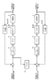
図1(a)において、ステージ位置決め装置は、定盤1、定盤1と不図示の軸受(例えば静圧軸受)を介して定盤1上を移動するステージ2、ステージ2をY方向へ案内するビーム状のX移動体3、ステージ2をX方向へ案内するX移動体3に略直交するビーム状のY移動体4、及びX移動体3及びY移動体4の姿勢(例えば回転変位や並進変位等)を制御する制御部を有する。この制御部は、X移動体3の両端に配置されてX移動体3をX方向に駆動するリニアモータ5a及びリニアモータ5b、Y移動体4の両端に配置されてY移動体4をY方向に駆動するリニアモータ6a及びリニアモータ6b、静圧パッド8aと8bとを介してそれぞれY移動体4のY方向への動きを案内するYガイド7a及びYガイド7b、X移動体3の姿勢(例えばX方向変位やθz方向回転変位等)を計測するレーザ干渉計9a及びレーザ干渉計9b、及びY移動体4の姿勢(例えばY方向変位やθz方向回転変位等)を計測するレーザ干渉計10a及びレーザ干渉計10bを含む。
【0020】
ステージ2は、例えば、図1(b)に示す構成を含み、X移動体3に摺動自在に支持されてX移動体3に沿って案内されてY方向に動き、Y移動体4に摺動自在に支持されてY移動体4に沿ってX方向に動く。静圧パッド8a、8bが装着されるY移動体4は、Yガイド7a、7bに沿ってY方向に動く。Yガイド7a、7bは定盤1上に固定されている。X移動体3の両端には永久磁石が固定されており、リニアモータ5a、5bのコイルに電流を流すことによって、X移動体3をX方向に駆動することができる。Y移動体4の両端にも永久磁石が固定されており、リニアモータ6a、6bのコイルに電流を流すことによって、Y移動体4をY方向に駆動することができる。また、静圧パッド8a、8bとYガイド7a、7bとの間には間隙があるため、その間隙だけY移動体4はθz方向に回転することができる。さらに、X移動体3もステージ2と軸受との間隙だけθz方向に回転することができる。
【0021】
図2は、本発明の好適な実施形態に係るステージ位置決め装置においてX移動体3及びY移動体4のそれぞれのZ軸まわりの軸回転変位を制御する制御部の構成を例示するブロック図である。
【0022】
図2において、この制御部は、例えば、Y移動体4が所定の目標回転角度θz0になるように制御演算を行うPIDコントローラ11、X移動体3が所定の目標回転角度θz0’になるように制御演算を行なうPIDコントローラ12、電流増幅を行なうアンプ13及びアンプ14、所定の周波数特性を有するフィルタ15を含む。
【0023】
まず、Y移動体4の回転角度θzはレーザ干渉計10a、10bによって計測される。計測されたY移動体4の回転角度θzと目標回転角度θz0との差はPIDコントローラ11に入力される。PIDコントローラ11はこの入力に対して比例項、積分項、微分項を用いた制御信号の演算(PID演算)を行なう。アンプ13はPIDコントローラ11からの出力を増幅する。リニアモータ6a、6bはアンプからの出力に基づいてY移動体4を駆動する。Y移動体4が駆動されたときの回転角度θzはレーザ干渉計10a、10bによって計測され、その計測結果はPIDコントローラ11にフィードバックされる。また、レーザ干渉計10a、10bにより計測された回転角度θzと目標回転角度θz0との差は、フィルタ15にも入力され、後述の所定のフィルタ演算を行った後にPIDコントローラ12への入力に加算される。
【0024】
一方、X移動体3の回転角度θz’はレーザ干渉計9a、9bによって計測される。計測されたX移動体3の回転角度θz’と目標回転角度θz0’との差、及び、後述の所定のフィルタ演算が行われたY移動体4の回転角度θzと目標回転角度θz0との差がPIDコントローラ12に入力される。PIDコントローラ12はこの入力に対してPID演算を行う。アンプ14はPIDコントローラ12からの出力を増幅する。リニアモータ5a、5bはアンプ14からの出力に基づいてX移動体3を駆動する。X移動体3が駆動されたときの回転角度θz’はレーザ干渉計9a、9bによって計測され、その計測結果はPIDコントローラ12にフィードバックされる。このように、Y移動体4の回転角度θzと目標回転角度θz0との差がPIDコントローラ12へ入力されることにより、X移動体3はY移動体4に対する制御結果に追従して移動することができる。
【0025】
本実施形態では図2の制御部において、例えば、X移動体3及びY移動体4の回転角度と目標回転角度との差の計算、PIDコントローラ11、12の演算、フィルタ15の演算をコンピュータ上のソフトウェアとして実現しているがこれに限るものではない。これらの一部または全部は、アナログ演算素子及びデジタル演算素子の少なくとも一方を含むハードウェアとして実現してもよい。
【0026】
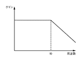
図3は、図2に示したフィルタ15が有する周波数特性を示す図である。フィルタ15は、例えば、Y移動体4の回転変位を示す信号が有する所定の周波数f0より高い周波数成分を抑えるように設計されている。これによって、フィルタ15はY移動体4の回転変位を示す信号に発生する余分な高周波成分を除去し、X移動体3をより精密に制御することができる。
【0027】
図4は、図3とは異なる周波数特性を有するフィルタ15の周波数特性を示す図である。このフィルタ15は、X移動体3の目標回転角度を示す信号の周波数応答のピーク値h1及びその周波数f1に合わせて、周波数応答のf1とh1の値を設定することによって、X移動体3をさらに高精度にY移動体4へ追従させることができる。
【0028】
さらに、PIDコントーラ12の積分項の係数をゼロに設定して積分演算を行なわないようにすることによって、X移動体3が軸受に過大な力で押し付けられる状況を回避することもできる。
【0029】
以上のように、本発明の好適な実施の形態によれば、機械的な要素を移動体に付加して装置を複雑化することなく、制御装置を改良することによって、移動体とステージとの間で生じ得る過剰な拘束及びそれによって生じる振動を防ぐことができる。本発明の好適な実施の形態における制御装置は、ソフトウェアによって低コストで実現することもできる。
【0030】
また、第2の移動体の姿勢(例えば回転変位や並進変位等)を制御する制御系に第1の移動体の姿勢(例えば回転変位や並進変位等)を制御する信号が入力されることによって、第2の移動体の追従性能を変化することができる。例えば、第2の移動体を制御する制御系の出力信号における周波数応答のピーク値及びその周波数に合わせてフィルタの周波数応答を設定することによって、第2の移動体をさらに精密に第1の移動体に追従させることができる。
[第2の実施形態]
図5は、本発明の好適な第2の実施の形態に係るステージ位置決め装置の制御装置において、X移動体3及びY移動体4のそれぞれのZ軸まわりの回転変位を制御する制御部の構成を示すブロック図である。第1の実施形態と類似する要素については同じ符号を用いている。第1の実施形態と異なる点は、所定の周波数特性を有するフィルタ16を設けたことである。このフィルタ16は、X移動体3の回転角度θz’と目標回転角度θz0’との差を示す信号に対して所定の演算を行い、その結果をPIDコントローラ11への入力に加算する。これによって、図2においてY移動体4に回転変位が生じたときにX移動体3をY移動体4に追従させるのと同様に、X移動体3に回転変位が生じたときにY移動体4をX移動体3に追従させることができる。
[他の実施形態]
次に、本発明のステージ位置決め装置を半導体デバイスの製造プロセスで用いられる露光装置に適用した場合の実施の形態について説明する。
【0031】
図6は、本発明のステージ位置決め装置を半導体デバイスの製造プロセスに適用した場合に用いられる露光装置の概念図を示したものである。
【0032】
本発明の好適な実施形態における露光装置60は、照明光学系61、レティクル62、投影光学系63、基板64、ステージ65で構成される。照明光学系61は、例えば、エキシマレーザ、フッ素エキシマレーザなどを光源とした紫外光を露光光として用いることができる。照明光学系61からの光は、レティクル62に照射される。レティクル62を通った光は、投影光学系63を通して、基板64上に焦点を結び、基板64表面に塗布された感光材を露光する。基板64は、本発明のステージ位置決め装置を適用したステージ65により、所定の位置へ移動される。
【0033】
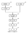
図7は、上記の露光装置を用いた半導体デバイスの全体的な製造プロセスのフローである。ステップ1(回路設計)では半導体デバイスの回路設計を行なう。ステップ2(マスク作製)では設計した回路パターンに基づいてマスクを作製する。一方、ステップ3(ウエハ製造)ではシリコン等の材料を用いてウエハを製造する。ステップ4(ウエハプロセス)は前工程と呼ばれ、上記のマスクとウエハを用いて、リソグラフィ技術によってウエハ上に実際の回路を形成する。次のステップ5(組み立て)は後工程と呼ばれ、ステップ4によって作製されたウエハを用いて半導体チップ化する工程であり、アッセンブリ工程(ダイシング、ボンディング)、パッケージング工程(チップ封入)等の組立て工程を含む。ステップ6(検査)ではステップ5で作製された半導体デバイスの動作確認テスト、耐久性テスト等の検査を行なう。こうした工程を経て半導体デバイスが完成し、これを出荷(ステップ7)する。
【0034】
図8は、上記ウエハプロセスの詳細なフローを示す。ステップ11(酸化)ではウエハの表面を酸化させる。ステップ12(CVD)ではウエハ表面に絶縁膜を成膜する。ステップ13(電極形成)ではウエハ上に電極を蒸着によって形成する。ステップ14(イオン打込み)ではウエハにイオンを打ち込む。ステップ15(レジスト処理)ではウエハに感光剤を塗布する。ステップ16(露光)では上記の露光装置を用いてウエハを精密に移動させ、回路パターンをウエハに転写する。ステップ17(現像)では露光したウエハを現像する。ステップ18(エッチング)では現像したレジスト像以外の部分を削り取る。ステップ19(レジスト剥離)ではエッチングが済んで不要となったレジストを取り除く。これらのステップを繰り返し行なうことによって、ウエハ上に多重に回路パターンを形成する。
【0035】
上記のプロセスを用いることにより、露光工程においてステージが移動するときに生じる振動が抑えられるため、回路パターンをより高精度にウエハに転写することができる。
【0036】
【発明の効果】
本発明によれば、例えば、第1の移動体の姿勢を制御する信号に基づいて第2の移動体の姿勢を制御することにより、ステージを精密に移動するステージ位置決め装置及びその制御方法、露光装置、半導体デバイスの製造方法を提供することができる。
【図面の簡単な説明】
【図1】本発明の好適な実施の形態に係るステージ位置決め装置の構成を示すブロック図である。
【図2】図1におけるX移動体及びY移動体のそれぞれのZ軸まわりの回転変位を制御する制御部の構成を示すブロック図である。
【図3】図2におけるフィルタの周波数特性を示す図である。
【図4】図2におけるフィルタの他の周波数特性を示す図である。
【図5】本発明の好適な第2の実施の形態に係るステージ位置決め装置の制御装置において、X移動体及びY移動体のそれぞれのZ軸まわりの回転変位を制御する制御部の構成を示すブロック図である。
【図6】本発明のステージ位置決め装置を半導体デバイスの製造プロセスに適用した場合に用いられる露光装置の概念図である。
【図7】半導体デバイスの全体的な製造プロセスのフローを示す図である。
【図8】ウエハプロセスの詳細なフローを示す図である。
【符号の説明】
1:定盤、2:ステージ、3:X移動体、4:Y移動体、5a、5b、6a、6b:リニアモータ、7a、7b:Yガイド、8a、8b:静圧パッド、9a、9b、10a、10b:レーザ干渉計、11、12:PIDコントローラ、13、14:アンプ、15、16:フィルタ[0001]
BACKGROUND OF THE INVENTION
The present invention relates to a stage positioning apparatus for driving a stage, a control method therefor, an exposure apparatus, and a semiconductor device manufacturing method.
[0002]
[Prior art]
Many devices have a configuration in which an object on a stage is positioned by a stage moving on a surface plate. In such an apparatus, it has two beam-like moving bodies that can move in two directions orthogonal to each other, and a stage that moves according to the moving bodies, and these moving bodies are guided in each direction by a guide. There is an apparatus of a type that drives the stage. Since this type of apparatus has a motor for driving the moving body at both ends of the moving body, a motor having an excellent driving capability can be arranged, and the stage can be moved quickly. Further, since the stage and the motor are separated, the motor can be efficiently cooled. However, in this type of apparatus, the two moving bodies may thermally expand, there may be a shift in parallelism between the respective moving bodies and the motor, or the moving bodies may rotate in the horizontal direction. For this reason, an excessively constrained state is likely to occur between the movable body and the stage that are originally relatively movable. As described above, if excessive restraint occurs between the moving body and the stage, the moving body and the stage may come into contact with each other and cannot move with each other, or the positioning accuracy of the stage may deteriorate due to vibration caused by interference between the two moving bodies. It was.
[0003]
In the method disclosed in Japanese Patent Application Laid-Open No. 9-34135, “Stage and Stage Driving Method”, mechanical means are provided to make the fitting tolerance between the first movable body and the stage highly accurate, and there is no backlash. On the other hand, this problem is avoided by loosely restraining the fit between the second moving body and the stage.
[0004]
[Problems to be solved by the invention]
However, the conventional method has a problem that a new vibration can be caused by providing a mechanism such as a spring. In addition, it is difficult to position the stage with high precision in order to control the movable body while firmly restraining one of the moving bodies. In addition, since a mechanism such as a spring is provided between the second moving body and the bearing, the apparatus is complicated.
[0005]
The present invention has been made in view of the above-described problems. For example, the stage is moved accurately by controlling the attitude of the second moving body based on a signal for controlling the attitude of the first moving body. An object of the present invention is to provide a stage positioning apparatus, a control method therefor, an exposure apparatus, and a semiconductor device manufacturing method.
[0006]
[Means for Solving the Problems]
A first aspect of the present invention relates to a stage positioning apparatus, a first moving body that is movable in a first direction, and a second movement that is movable in a second direction different from the first direction. A stage, a stage slidably supported by the first moving body and the second moving body, and guided in the first and second directions, respectively, and the first of the first moving body. control when controlling a first control unit for controlling the third direction of orientation different from the second direction, the third direction of orientation of the first mobile in said first control unit And a second control unit that controls the posture of the second moving body in the third direction based on the deviation .
[0007]
According to a preferred embodiment of the present invention, the first control unit and the second control unit are configured to measure the posture of the moving body based on a measurement result by the measurement unit. And an actuator for driving the moving body.
[0008]
According to a preferred embodiment of the present invention, the actuator is a linear motor.
[0009]
According to a preferred embodiment of the present invention, the second control unit controls the posture of the second moving body in the third direction based on the control deviation subjected to a predetermined filter process. .
[0010]
According to a preferred embodiment of the present invention, the first and second directions are orthogonal to each other, and the third direction is a rotational direction around an axis orthogonal to the first and second directions . is there.
[0011]
According to a preferred embodiment of the present invention, the first moving body and the second moving body are arranged so that end portions thereof are parallel to the first direction and the second direction, respectively. And a bearing that slides with a predetermined gap that is rotatable in the third direction with respect to the guide, and guides in the first and second directions via the guide and the bearing. Is done.
[0012]
According to a preferred embodiment of the present invention, the first control unit controls the attitude of the first moving body in the third direction by performing each operation of a proportional term, an integral term, and a differential term. The second control unit obtains a signal for controlling the posture of the second moving body in the third direction by performing each calculation of the proportional term and the differential term.
[0013]
According to a preferred embodiment of the present invention, the first control unit, based on the control deviation in controlling the said third direction of orientation of the second mobile in the second control unit And controlling the posture of the first moving body in the third direction .
[0014]
According to a second aspect of the present invention, there is provided a first moving body that is movable in a first direction and a second moving body that is movable in a second direction different from the first direction. A first control for controlling a posture of the first moving body in a third direction different from the first and second directions, according to a control method of the stage positioning device for guiding the stage in each of the two directions. And controlling the attitude of the second moving body in the third direction based on a control deviation when controlling the attitude of the first moving body in the third direction in the first control step. And a second control step.
[0015]
According to a preferred embodiment of the present invention, the first control step, based on the control deviation in controlling the said third direction of orientation of the second mobile in the second control step And controlling the posture of the first moving body in the third direction .
[0016]
According to a third aspect of the present invention, there is provided an exposure apparatus, wherein a pattern is transferred using a stage positioning device controlled by a control method according to claim 8 or claim 9.
[0017]
According to a fourth aspect of the present invention, there is provided a semiconductor device manufacturing method, comprising: an application step of applying a photosensitive material to a substrate; and the exposure apparatus according to
[0018]
DETAILED DESCRIPTION OF THE INVENTION
DESCRIPTION OF EXEMPLARY EMBODIMENTS Hereinafter, preferred embodiments of the invention will be described with reference to the accompanying drawings.
[First embodiment]
FIG. 1 is a diagram showing a schematic configuration of a stage positioning device according to a preferred embodiment of the present invention. FIG. 1 (a) is a plan view of the stage positioning device, and FIG. 1 (b) is a diagram of the stage positioning device. It is a perspective view.
[0019]
In FIG. 1 (a), the stage positioning device guides the stage 2, the stage 2 moving on the surface plate 1 via the surface plate 1, the surface plate 1, and a bearing (not shown) (for example, a hydrostatic bearing) in the Y direction. The beam-like
[0020]
The stage 2 includes, for example, the configuration shown in FIG. 1B, is slidably supported by the
[0021]
FIG. 2 is a block diagram illustrating the configuration of a control unit that controls the rotational displacement about the Z axis of each of the
[0022]
In FIG. 2, for example, the control unit performs a control calculation so that the
[0023]
First, the rotation angle θz of the
[0024]
On the other hand, the rotation angle θz ′ of the
[0025]
In the present embodiment, in the control unit of FIG. 2, for example, calculation of the difference between the rotation angle of the
[0026]
FIG. 3 is a diagram showing frequency characteristics of the
[0027]
FIG. 4 is a diagram showing frequency characteristics of the
[0028]
Furthermore, by setting the coefficient of the integral term of the
[0029]
As described above, according to a preferred embodiment of the present invention, by adding a mechanical element to a moving body and improving the control device without complicating the apparatus, the moving body and the stage can be improved. It is possible to prevent excessive restraint and vibration caused thereby. The control device according to a preferred embodiment of the present invention can be realized at low cost by software.
[0030]
Further, when a signal for controlling the posture (for example, rotational displacement, translational displacement, etc.) of the first movable body is input to the control system for controlling the posture (for example, rotational displacement, translational displacement, etc.) of the second movable body. The follow-up performance of the second moving body can be changed. For example, by setting the frequency response peak value in the output signal of the control system that controls the second moving body and the frequency response of the filter in accordance with the frequency, the second moving body can be moved more precisely. You can follow the body.
[Second Embodiment]
FIG. 5 shows the configuration of a control unit that controls the rotational displacement of each of the
[Other embodiments]
Next, an embodiment in which the stage positioning apparatus of the present invention is applied to an exposure apparatus used in a semiconductor device manufacturing process will be described.
[0031]
FIG. 6 shows a conceptual diagram of an exposure apparatus used when the stage positioning apparatus of the present invention is applied to a semiconductor device manufacturing process.
[0032]
An exposure apparatus 60 according to a preferred embodiment of the present invention includes an illumination
[0033]
FIG. 7 is a flow of an entire manufacturing process of a semiconductor device using the above exposure apparatus. In step 1 (circuit design), a semiconductor device circuit is designed. In step 2 (mask fabrication), a mask is fabricated based on the designed circuit pattern. On the other hand, in step 3 (wafer manufacture), a wafer is manufactured using a material such as silicon. Step 4 (wafer process) is called a pre-process, and an actual circuit is formed on the wafer by lithography using the mask and wafer. The next step 5 (assembly) is referred to as a post-process, and is a process for forming a semiconductor chip using the wafer produced in
[0034]
FIG. 8 shows a detailed flow of the wafer process. In step 11 (oxidation), the wafer surface is oxidized. In step 12 (CVD), an insulating film is formed on the wafer surface. In step 13 (electrode formation), an electrode is formed on the wafer by vapor deposition. In step 14 (ion implantation), ions are implanted into the wafer. In step 15 (resist process), a photosensitive agent is applied to the wafer. In step 16 (exposure), the wafer is precisely moved using the above exposure apparatus, and the circuit pattern is transferred to the wafer. In step 17 (development), the exposed wafer is developed. In step 18 (etching), portions other than the developed resist image are removed. In step 19 (resist stripping), unnecessary resist after etching is removed. By repeating these steps, multiple circuit patterns are formed on the wafer.
[0035]
By using the above process, the vibration generated when the stage moves in the exposure process can be suppressed, so that the circuit pattern can be transferred to the wafer with higher accuracy.
[0036]
【The invention's effect】
According to the present invention, for example, a stage positioning apparatus that accurately moves a stage by controlling the attitude of the second moving body based on a signal for controlling the attitude of the first moving body, a control method therefor, and exposure An apparatus and a method for manufacturing a semiconductor device can be provided.
[Brief description of the drawings]
FIG. 1 is a block diagram showing a configuration of a stage positioning apparatus according to a preferred embodiment of the present invention.
FIG. 2 is a block diagram showing a configuration of a control unit that controls rotational displacement about the Z axis of each of the X moving body and the Y moving body in FIG. 1;
FIG. 3 is a diagram showing frequency characteristics of the filter in FIG. 2;
FIG. 4 is a diagram illustrating another frequency characteristic of the filter in FIG.
FIG. 5 shows the configuration of a control unit for controlling the rotational displacement about the Z axis of each of the X moving body and the Y moving body in the control device for the stage positioning device according to the preferred second embodiment of the present invention. It is a block diagram.
FIG. 6 is a conceptual diagram of an exposure apparatus used when the stage positioning apparatus of the present invention is applied to a semiconductor device manufacturing process.
FIG. 7 is a diagram showing a flow of an entire manufacturing process of a semiconductor device.
FIG. 8 is a diagram showing a detailed flow of a wafer process.
[Explanation of symbols]
1: surface plate, 2: stage, 3: X moving body, 4: Y moving body, 5a, 5b, 6a, 6b: linear motor, 7a, 7b: Y guide, 8a, 8b: static pressure pad, 9a,
Claims (12)
前記第1の方向とは異なる第2の方向に移動可能な第2の移動体と、
前記第1の移動体及び前記第2の移動体により摺動自在に支持され、前記第1、第2の方向に夫々案内されるステージと、
前記第1の移動体の前記第1、第2の方向と異なる第3の方向の姿勢を制御する第1の制御部と、
前記第1の制御部において前記第1の移動体の前記第3の方向の姿勢を制御する際の制御偏差に基づいて前記第2の移動体の前記第3の方向の姿勢を制御する第2の制御部と、
を備えることを特徴とするステージ位置決め装置。A first moving body movable in a first direction;
A second moving body movable in a second direction different from the first direction;
A stage that is slidably supported by the first moving body and the second moving body, and is guided in the first and second directions, respectively;
A first controller that controls a posture of the first moving body in a third direction different from the first and second directions;
A second control unit configured to control a posture of the second moving body in the third direction based on a control deviation when controlling the posture of the first moving body in the third direction in the first control unit ; A control unit of
A stage positioning apparatus comprising:
前記移動体の前記姿勢を計測する計測部と、
前記計測部による計測結果に基づいて前記移動体を駆動するアクチュエータと、
を有することを特徴とする請求項1に記載のステージ位置決め装置。The first control unit and the second control unit are:
A measuring unit for measuring the posture of the moving body;
An actuator for driving the moving body based on a measurement result by the measurement unit;
The stage positioning apparatus according to claim 1, further comprising:
前記第1の移動体の前記第1、第2の方向と異なる第3の方向の姿勢を制御する第1の制御工程と、
前記第1の制御工程において前記第1の移動体の前記第3の方向の姿勢を制御する際の制御偏差に基づいて前記第2の移動体の前記第3の方向の姿勢を制御する第2の制御工程と、
を含むことを特徴とするステージ位置決め装置の制御方法。The stage is guided in the first and second directions by a first moving body that can move in the first direction and a second moving body that can move in a second direction different from the first direction. A method for controlling a stage positioning apparatus for
A first control step of controlling a posture of the first moving body in a third direction different from the first and second directions;
A second control unit configured to control the posture of the second moving body in the third direction based on a control deviation when controlling the posture of the first moving body in the third direction in the first control step ; Control process of
A control method for a stage positioning apparatus, comprising:
基板に感光材を塗布する塗布工程と、
前記塗布工程で前記感光材が塗布された前記基板に請求項11に記載の露光装置を利用してパターンを転写する露光工程と、
前記露光工程で前記パターンが転写された前記基板の前記感光材を現像する現像工程と、
を有することを特徴とする半導体デバイスの製造方法。A method for manufacturing a semiconductor device, comprising:
An application process for applying a photosensitive material to the substrate;
An exposure step of transferring a pattern using the exposure apparatus according to claim 11 to the substrate on which the photosensitive material has been applied in the application step;
A developing step of developing the photosensitive material of the substrate on which the pattern has been transferred in the exposure step;
A method for manufacturing a semiconductor device, comprising:
Priority Applications (7)
| Application Number | Priority Date | Filing Date | Title |
|---|---|---|---|
| JP2002050289A JP3679767B2 (en) | 2002-02-26 | 2002-02-26 | Stage positioning apparatus, control method therefor, exposure apparatus, and semiconductor device manufacturing method |
| EP03250992A EP1347498A3 (en) | 2002-02-26 | 2003-02-18 | Stage alignment apparatus and control method therefor |
| US10/368,621 US6975383B2 (en) | 2002-02-26 | 2003-02-20 | Stage alignment apparatus and its control method, exposure apparatus, and semiconductor device manufacturing method |
| TW092103801A TWI228206B (en) | 2002-02-26 | 2003-02-24 | Stage alignment apparatus and its control method, exposure apparatus, and semiconductor device manufacturing method |
| CNB031063934A CN1240120C (en) | 2002-02-26 | 2003-02-26 | Desk rack positioning and its control and explosure device and method for producing semiconductor device |
| KR1020030011989A KR100560221B1 (en) | 2002-02-26 | 2003-02-26 | Stage alignment apparatus and its control method, exposure apparatus, and semiconductor device manufacturing method |
| US11/188,620 US7119879B2 (en) | 2002-02-26 | 2005-07-26 | Stage alignment apparatus and its control method, exposure apparatus, and semiconductor device manufacturing method |
Applications Claiming Priority (1)
| Application Number | Priority Date | Filing Date | Title |
|---|---|---|---|
| JP2002050289A JP3679767B2 (en) | 2002-02-26 | 2002-02-26 | Stage positioning apparatus, control method therefor, exposure apparatus, and semiconductor device manufacturing method |
Publications (2)
| Publication Number | Publication Date |
|---|---|
| JP2003249439A JP2003249439A (en) | 2003-09-05 |
| JP3679767B2 true JP3679767B2 (en) | 2005-08-03 |
Family
ID=27784572
Family Applications (1)
| Application Number | Title | Priority Date | Filing Date |
|---|---|---|---|
| JP2002050289A Expired - Fee Related JP3679767B2 (en) | 2002-02-26 | 2002-02-26 | Stage positioning apparatus, control method therefor, exposure apparatus, and semiconductor device manufacturing method |
Country Status (6)
| Country | Link |
|---|---|
| US (2) | US6975383B2 (en) |
| EP (1) | EP1347498A3 (en) |
| JP (1) | JP3679767B2 (en) |
| KR (1) | KR100560221B1 (en) |
| CN (1) | CN1240120C (en) |
| TW (1) | TWI228206B (en) |
Families Citing this family (13)
| Publication number | Priority date | Publication date | Assignee | Title |
|---|---|---|---|---|
| JP3679767B2 (en) * | 2002-02-26 | 2005-08-03 | キヤノン株式会社 | Stage positioning apparatus, control method therefor, exposure apparatus, and semiconductor device manufacturing method |
| EP1494078A1 (en) * | 2003-07-01 | 2005-01-05 | ASML Netherlands B.V. | Lithographic apparatus and device manufacturing method. |
| JP4478435B2 (en) | 2003-11-17 | 2010-06-09 | キヤノン株式会社 | Exposure apparatus and device manufacturing method |
| JP4478470B2 (en) * | 2004-01-26 | 2010-06-09 | キヤノン株式会社 | Positioning stage device |
| JP2006222312A (en) * | 2005-02-10 | 2006-08-24 | Canon Inc | Apparatus and method for stage control, stage apparatus and exposure apparatus |
| JP4701008B2 (en) * | 2005-05-25 | 2011-06-15 | 東芝機械株式会社 | Transfer device with gimbal mechanism |
| US7782446B2 (en) * | 2007-03-01 | 2010-08-24 | Asml Netherlands B.V. | Stage system and lithographic apparatus comprising such stage system |
| US8285418B2 (en) * | 2009-07-23 | 2012-10-09 | Kla-Tencor Corporation | Dual scanning stage |
| WO2011055826A1 (en) * | 2009-11-09 | 2011-05-12 | 日本精工株式会社 | Mask holding mechanism |
| JP5651323B2 (en) * | 2009-11-09 | 2015-01-07 | 富士機械製造株式会社 | Plasma processing apparatus and plasma processing method |
| NL2006929A (en) * | 2010-08-05 | 2012-02-13 | Asml Netherlands Bv | Imprint lithography. |
| JP6273369B2 (en) | 2013-12-20 | 2018-01-31 | エーエスエムエル ネザーランズ ビー.ブイ. | Lithographic apparatus and device manufacturing method |
| CN110546573B (en) | 2017-04-11 | 2022-10-04 | Asml荷兰有限公司 | Lithographic apparatus |
Family Cites Families (18)
| Publication number | Priority date | Publication date | Assignee | Title |
|---|---|---|---|---|
| US5523843A (en) * | 1990-07-09 | 1996-06-04 | Canon Kabushiki Kaisha | Position detecting system |
| JP2887033B2 (en) | 1992-11-19 | 1999-04-26 | キヤノン株式会社 | Precision positioning device |
| US5760564A (en) * | 1995-06-27 | 1998-06-02 | Nikon Precision Inc. | Dual guide beam stage mechanism with yaw control |
| US5936710A (en) * | 1996-01-05 | 1999-08-10 | Canon Kabushiki Kaisha | Scanning type exposure apparatus, position control apparatus, and method therefor |
| JP3907252B2 (en) * | 1996-12-05 | 2007-04-18 | キヤノン株式会社 | Exposure apparatus, device manufacturing method, stage apparatus, and origin finding method |
| JP4146952B2 (en) * | 1999-01-11 | 2008-09-10 | キヤノン株式会社 | Exposure apparatus and device manufacturing method |
| JP3312297B2 (en) * | 1999-07-02 | 2002-08-05 | 住友重機械工業株式会社 | Stage position control device |
| DE60032568T2 (en) | 1999-12-01 | 2007-10-04 | Asml Netherlands B.V. | Positioning apparatus and lithographic apparatus provided therewith |
| EP1107067B1 (en) | 1999-12-01 | 2006-12-27 | ASML Netherlands B.V. | Positioning apparatus and lithographic apparatus comprising the same |
| TWI264617B (en) | 1999-12-21 | 2006-10-21 | Asml Netherlands Bv | Balanced positioning system for use in lithographic apparatus |
| EP1111469B1 (en) | 1999-12-21 | 2007-10-17 | ASML Netherlands B.V. | Lithographic apparatus with a balanced positioning system |
| TW546551B (en) * | 1999-12-21 | 2003-08-11 | Asml Netherlands Bv | Balanced positioning system for use in lithographic apparatus |
| JP3814453B2 (en) * | 2000-01-11 | 2006-08-30 | キヤノン株式会社 | Positioning apparatus, semiconductor exposure apparatus, and device manufacturing method |
| JP2001284437A (en) * | 2000-03-30 | 2001-10-12 | Canon Inc | Moving body guiding apparatus, method for guiding moving body and aligner using it |
| US6593997B1 (en) * | 2000-11-16 | 2003-07-15 | Nikon Corporation | Stage assembly including a reaction assembly |
| US6603531B1 (en) * | 2000-11-16 | 2003-08-05 | Nikon Corporation | Stage assembly including a reaction assembly that is connected by actuators |
| JP2002242983A (en) * | 2001-02-19 | 2002-08-28 | Canon Inc | Active vibration resistant system |
| JP3679767B2 (en) * | 2002-02-26 | 2005-08-03 | キヤノン株式会社 | Stage positioning apparatus, control method therefor, exposure apparatus, and semiconductor device manufacturing method |
-
2002
- 2002-02-26 JP JP2002050289A patent/JP3679767B2/en not_active Expired - Fee Related
-
2003
- 2003-02-18 EP EP03250992A patent/EP1347498A3/en not_active Withdrawn
- 2003-02-20 US US10/368,621 patent/US6975383B2/en not_active Expired - Fee Related
- 2003-02-24 TW TW092103801A patent/TWI228206B/en not_active IP Right Cessation
- 2003-02-26 KR KR1020030011989A patent/KR100560221B1/en not_active IP Right Cessation
- 2003-02-26 CN CNB031063934A patent/CN1240120C/en not_active Expired - Fee Related
-
2005
- 2005-07-26 US US11/188,620 patent/US7119879B2/en not_active Expired - Fee Related
Also Published As
| Publication number | Publication date |
|---|---|
| US20060044537A1 (en) | 2006-03-02 |
| CN1240120C (en) | 2006-02-01 |
| EP1347498A3 (en) | 2004-09-29 |
| CN1441476A (en) | 2003-09-10 |
| US7119879B2 (en) | 2006-10-10 |
| JP2003249439A (en) | 2003-09-05 |
| KR20030070854A (en) | 2003-09-02 |
| KR100560221B1 (en) | 2006-03-10 |
| US6975383B2 (en) | 2005-12-13 |
| US20030164930A1 (en) | 2003-09-04 |
| EP1347498A2 (en) | 2003-09-24 |
| TWI228206B (en) | 2005-02-21 |
| TW200307189A (en) | 2003-12-01 |
Similar Documents
| Publication | Publication Date | Title |
|---|---|---|
| US7119879B2 (en) | Stage alignment apparatus and its control method, exposure apparatus, and semiconductor device manufacturing method | |
| US7443619B2 (en) | Optical element holding apparatus, exposure apparatus and device manufacturing method | |
| JP3155936B2 (en) | Linear motor and stage apparatus, and scanning exposure apparatus and device manufacturing method using the same | |
| JP2005046941A (en) | Stage device with cable jogging unit | |
| JPH09219353A (en) | Stage apparatus, and aligner using it and device producing method using it | |
| JP3984841B2 (en) | Distortion measuring apparatus, distortion suppressing apparatus, exposure apparatus, and device manufacturing method | |
| JP2005327993A (en) | Positioning device, exposure device, and device-manufacturing method | |
| US7586218B2 (en) | Moving apparatus, exposure apparatus, and device manufacturing method | |
| JP2007329435A (en) | Stage apparatus, exposure apparatus, and manufacturing method of device | |
| JP2004146492A (en) | Euv aligner | |
| JPH10289943A (en) | Stage device and manufacture thereof | |
| JP4447949B2 (en) | Method for initializing positioning apparatus, exposure apparatus and device manufacturing method | |
| JP3919592B2 (en) | Stage apparatus, control method therefor, and exposure apparatus | |
| JP2006120798A (en) | Exposure apparatus | |
| JP2004281654A (en) | Drive mechanism, aligner employing it, and process for fabricating device | |
| JP4541849B2 (en) | Positioning device | |
| JP2004111653A (en) | Positioning device, exposure device applying the locating device thereto and manufacturing method of semiconductor device | |
| US20080143995A1 (en) | Moving apparatus | |
| JP3244872B2 (en) | Exposure apparatus and device manufacturing method using the same | |
| JP4011919B2 (en) | Moving apparatus, exposure apparatus, and semiconductor device manufacturing method | |
| JP2006156554A (en) | Stage device and aligner using the same, and device manufacturing method | |
| JP4174289B2 (en) | Positioning apparatus, exposure apparatus to which the positioning apparatus is applied, and device manufacturing method | |
| JP5539293B2 (en) | Exposure apparatus and device manufacturing method | |
| JP2000260690A (en) | X-ray aligner | |
| JPH09306815A (en) | Aligner and device producing method utilizing thereof |
Legal Events
| Date | Code | Title | Description |
|---|---|---|---|
| A977 | Report on retrieval |
Free format text: JAPANESE INTERMEDIATE CODE: A971007 Effective date: 20040507 |
|
| A131 | Notification of reasons for refusal |
Free format text: JAPANESE INTERMEDIATE CODE: A131 Effective date: 20040618 |
|
| A521 | Written amendment |
Free format text: JAPANESE INTERMEDIATE CODE: A523 Effective date: 20040817 |
|
| TRDD | Decision of grant or rejection written | ||
| A01 | Written decision to grant a patent or to grant a registration (utility model) |
Free format text: JAPANESE INTERMEDIATE CODE: A01 Effective date: 20050506 |
|
| A61 | First payment of annual fees (during grant procedure) |
Free format text: JAPANESE INTERMEDIATE CODE: A61 Effective date: 20050513 |
|
| R150 | Certificate of patent or registration of utility model |
Ref document number: 3679767 Country of ref document: JP Free format text: JAPANESE INTERMEDIATE CODE: R150 Free format text: JAPANESE INTERMEDIATE CODE: R150 |
|
| FPAY | Renewal fee payment (event date is renewal date of database) |
Free format text: PAYMENT UNTIL: 20090520 Year of fee payment: 4 |
|
| FPAY | Renewal fee payment (event date is renewal date of database) |
Free format text: PAYMENT UNTIL: 20100520 Year of fee payment: 5 |
|
| FPAY | Renewal fee payment (event date is renewal date of database) |
Free format text: PAYMENT UNTIL: 20100520 Year of fee payment: 5 |
|
| FPAY | Renewal fee payment (event date is renewal date of database) |
Free format text: PAYMENT UNTIL: 20110520 Year of fee payment: 6 |
|
| FPAY | Renewal fee payment (event date is renewal date of database) |
Free format text: PAYMENT UNTIL: 20120520 Year of fee payment: 7 |
|
| FPAY | Renewal fee payment (event date is renewal date of database) |
Free format text: PAYMENT UNTIL: 20120520 Year of fee payment: 7 |
|
| FPAY | Renewal fee payment (event date is renewal date of database) |
Free format text: PAYMENT UNTIL: 20130520 Year of fee payment: 8 |
|
| FPAY | Renewal fee payment (event date is renewal date of database) |
Free format text: PAYMENT UNTIL: 20140520 Year of fee payment: 9 |
|
| LAPS | Cancellation because of no payment of annual fees |