JP4701008B2 - Transfer device with gimbal mechanism - Google Patents
Transfer device with gimbal mechanism Download PDFInfo
- Publication number
- JP4701008B2 JP4701008B2 JP2005153003A JP2005153003A JP4701008B2 JP 4701008 B2 JP4701008 B2 JP 4701008B2 JP 2005153003 A JP2005153003 A JP 2005153003A JP 2005153003 A JP2005153003 A JP 2005153003A JP 4701008 B2 JP4701008 B2 JP 4701008B2
- Authority
- JP
- Japan
- Prior art keywords
- gimbal
- gimbal mechanism
- transfer device
- mold
- movable body
- Prior art date
- Legal status (The legal status is an assumption and is not a legal conclusion. Google has not performed a legal analysis and makes no representation as to the accuracy of the status listed.)
- Active
Links
- 230000007246 mechanism Effects 0.000 title claims description 84
- 239000000463 material Substances 0.000 claims description 20
- 230000002093 peripheral effect Effects 0.000 claims description 7
- 239000013307 optical fiber Substances 0.000 claims description 6
- 239000012778 molding material Substances 0.000 claims description 4
- 230000001678 irradiating effect Effects 0.000 claims description 3
- 238000010521 absorption reaction Methods 0.000 claims description 2
- 238000009281 ultraviolet germicidal irradiation Methods 0.000 claims description 2
- 239000011248 coating agent Substances 0.000 claims 1
- 238000000576 coating method Methods 0.000 claims 1
- 230000003247 decreasing effect Effects 0.000 claims 1
- 238000000465 moulding Methods 0.000 description 21
- 229920005989 resin Polymers 0.000 description 17
- 239000011347 resin Substances 0.000 description 17
- 238000003825 pressing Methods 0.000 description 15
- 239000000758 substrate Substances 0.000 description 14
- 238000006073 displacement reaction Methods 0.000 description 8
- 230000008859 change Effects 0.000 description 6
- 238000000034 method Methods 0.000 description 6
- 230000005484 gravity Effects 0.000 description 4
- 238000005339 levitation Methods 0.000 description 4
- VYPSYNLAJGMNEJ-UHFFFAOYSA-N silicon dioxide Inorganic materials O=[Si]=O VYPSYNLAJGMNEJ-UHFFFAOYSA-N 0.000 description 4
- 230000006870 function Effects 0.000 description 3
- 238000010438 heat treatment Methods 0.000 description 3
- 239000011810 insulating material Substances 0.000 description 2
- 238000001459 lithography Methods 0.000 description 2
- 239000010453 quartz Substances 0.000 description 2
- 229920005992 thermoplastic resin Polymers 0.000 description 2
- 238000005452 bending Methods 0.000 description 1
- 239000000919 ceramic Substances 0.000 description 1
- 238000006243 chemical reaction Methods 0.000 description 1
- 230000008602 contraction Effects 0.000 description 1
- 238000001816 cooling Methods 0.000 description 1
- 239000013256 coordination polymer Substances 0.000 description 1
- 230000006837 decompression Effects 0.000 description 1
- 230000000694 effects Effects 0.000 description 1
- 238000010894 electron beam technology Methods 0.000 description 1
- 238000000605 extraction Methods 0.000 description 1
- 239000010408 film Substances 0.000 description 1
- 238000007667 floating Methods 0.000 description 1
- 239000011521 glass Substances 0.000 description 1
- 238000002347 injection Methods 0.000 description 1
- 239000007924 injection Substances 0.000 description 1
- 238000005259 measurement Methods 0.000 description 1
- 230000010355 oscillation Effects 0.000 description 1
- 230000000149 penetrating effect Effects 0.000 description 1
- 230000008569 process Effects 0.000 description 1
- 230000009467 reduction Effects 0.000 description 1
- 239000005394 sealing glass Substances 0.000 description 1
- 229910052710 silicon Inorganic materials 0.000 description 1
- 239000010703 silicon Substances 0.000 description 1
- 238000001179 sorption measurement Methods 0.000 description 1
- 230000001629 suppression Effects 0.000 description 1
- 239000010409 thin film Substances 0.000 description 1
- 239000012780 transparent material Substances 0.000 description 1
- 230000003313 weakening effect Effects 0.000 description 1
Images


Classifications
-
- G—PHYSICS
- G03—PHOTOGRAPHY; CINEMATOGRAPHY; ANALOGOUS TECHNIQUES USING WAVES OTHER THAN OPTICAL WAVES; ELECTROGRAPHY; HOLOGRAPHY
- G03F—PHOTOMECHANICAL PRODUCTION OF TEXTURED OR PATTERNED SURFACES, e.g. FOR PRINTING, FOR PROCESSING OF SEMICONDUCTOR DEVICES; MATERIALS THEREFOR; ORIGINALS THEREFOR; APPARATUS SPECIALLY ADAPTED THEREFOR
- G03F7/00—Photomechanical, e.g. photolithographic, production of textured or patterned surfaces, e.g. printing surfaces; Materials therefor, e.g. comprising photoresists; Apparatus specially adapted therefor
- G03F7/0002—Lithographic processes using patterning methods other than those involving the exposure to radiation, e.g. by stamping
-
- G—PHYSICS
- G11—INFORMATION STORAGE
- G11B—INFORMATION STORAGE BASED ON RELATIVE MOVEMENT BETWEEN RECORD CARRIER AND TRANSDUCER
- G11B7/00—Recording or reproducing by optical means, e.g. recording using a thermal beam of optical radiation by modifying optical properties or the physical structure, reproducing using an optical beam at lower power by sensing optical properties; Record carriers therefor
- G11B7/24—Record carriers characterised by shape, structure or physical properties, or by the selection of the material
- G11B7/26—Apparatus or processes specially adapted for the manufacture of record carriers
-
- B—PERFORMING OPERATIONS; TRANSPORTING
- B29—WORKING OF PLASTICS; WORKING OF SUBSTANCES IN A PLASTIC STATE IN GENERAL
- B29C—SHAPING OR JOINING OF PLASTICS; SHAPING OF MATERIAL IN A PLASTIC STATE, NOT OTHERWISE PROVIDED FOR; AFTER-TREATMENT OF THE SHAPED PRODUCTS, e.g. REPAIRING
- B29C59/00—Surface shaping of articles, e.g. embossing; Apparatus therefor
- B29C59/02—Surface shaping of articles, e.g. embossing; Apparatus therefor by mechanical means, e.g. pressing
-
- B—PERFORMING OPERATIONS; TRANSPORTING
- B81—MICROSTRUCTURAL TECHNOLOGY
- B81C—PROCESSES OR APPARATUS SPECIALLY ADAPTED FOR THE MANUFACTURE OR TREATMENT OF MICROSTRUCTURAL DEVICES OR SYSTEMS
- B81C99/00—Subject matter not provided for in other groups of this subclass
-
- B—PERFORMING OPERATIONS; TRANSPORTING
- B82—NANOTECHNOLOGY
- B82Y—SPECIFIC USES OR APPLICATIONS OF NANOSTRUCTURES; MEASUREMENT OR ANALYSIS OF NANOSTRUCTURES; MANUFACTURE OR TREATMENT OF NANOSTRUCTURES
- B82Y10/00—Nanotechnology for information processing, storage or transmission, e.g. quantum computing or single electron logic
-
- B—PERFORMING OPERATIONS; TRANSPORTING
- B82—NANOTECHNOLOGY
- B82Y—SPECIFIC USES OR APPLICATIONS OF NANOSTRUCTURES; MEASUREMENT OR ANALYSIS OF NANOSTRUCTURES; MANUFACTURE OR TREATMENT OF NANOSTRUCTURES
- B82Y40/00—Manufacture or treatment of nanostructures
-
- G—PHYSICS
- G03—PHOTOGRAPHY; CINEMATOGRAPHY; ANALOGOUS TECHNIQUES USING WAVES OTHER THAN OPTICAL WAVES; ELECTROGRAPHY; HOLOGRAPHY
- G03F—PHOTOMECHANICAL PRODUCTION OF TEXTURED OR PATTERNED SURFACES, e.g. FOR PRINTING, FOR PROCESSING OF SEMICONDUCTOR DEVICES; MATERIALS THEREFOR; ORIGINALS THEREFOR; APPARATUS SPECIALLY ADAPTED THEREFOR
- G03F9/00—Registration or positioning of originals, masks, frames, photographic sheets or textured or patterned surfaces, e.g. automatically
-
- H—ELECTRICITY
- H01—ELECTRIC ELEMENTS
- H01L—SEMICONDUCTOR DEVICES NOT COVERED BY CLASS H10
- H01L21/00—Processes or apparatus adapted for the manufacture or treatment of semiconductor or solid state devices or of parts thereof
- H01L21/02—Manufacture or treatment of semiconductor devices or of parts thereof
Description
本発明は、リソグラフィ技術を用いて型の表面に形成された微細な凹凸パターンを被成形品の表面に転写する転写装置に係り、特に型と被成形品の位置ずれ(横ずれ)を小さく抑えることのできる転写装置に関する。 The present invention relates to a transfer device that transfers a fine uneven pattern formed on the surface of a mold to the surface of a molded product using a lithography technique, and in particular, suppresses misalignment (lateral deviation) between the mold and the molded product. The present invention relates to a transfer device capable of performing the above.
近年、電子線描画法などで石英基板等に超微細なパターンを形成して型(テンプレート、スタンパ)を作成し、被成形品として被転写基板表面に形成されたレジスト膜に前記型を所定の圧力で押圧して、当該型に形成されたパターンを転写するナノインプリント技術が研究開発されている(非特許文献1参照)。 In recent years, a mold (template, stamper) is formed by forming an ultrafine pattern on a quartz substrate or the like by an electron beam drawing method, and the mold is applied to a resist film formed on a surface of a transfer substrate as a molded product. A nanoimprint technique for transferring a pattern formed on the mold by pressing with pressure has been researched and developed (see Non-Patent Document 1).
ところで、テンプレート、スタンパ等の型にリソグラフィ技術を用いて形成された超微細な凹凸のパターンを被成形品に押圧し転写するとき、前記パターンが形成された型の転写面と被成形品の表面とが密着しかつ均一に接触し、型に形成された微細な凹凸のパターンが被成形品に精確に転写されるように、被成形品の表面に対して前記型の姿勢を高精度に微調整する必要がある。 By the way, when an ultra-fine uneven pattern formed on a mold such as a template or a stamper is pressed and transferred to a molded product, the transfer surface of the mold on which the pattern is formed and the surface of the molded product Are closely and uniformly in contact with each other so that the fine uneven pattern formed on the mold can be accurately transferred to the molded product. It needs to be adjusted.
型の上記微調整を行う構成として、前記非特許文献1においては、型を保持する保持部をフレキシブルな素材によって構成し、型の転写面を被成形品の表面へ押圧したときに、被成形品の表面に倣って型の保持部を従動的に被成形品の表面に追従させる構成である。 As a configuration for performing the fine adjustment of the mold, in Non-Patent Document 1, the holding portion that holds the mold is formed of a flexible material, and when the transfer surface of the mold is pressed against the surface of the molded product, The structure is such that the holding portion of the mold follows the surface of the product to be molded following the surface of the product.
このように、従動的に型の姿勢を微調整する構成の場合、型を被成形品の表面に押圧したとき、被成形品に損傷を与えないようにできるだけ小さな圧力で押圧する必要があり、型の保持部は姿勢制御用の小さな圧力をもとに構成されている。 In this way, in the case of a configuration that finely adjusts the posture of the mold passively, when the mold is pressed against the surface of the molded product, it is necessary to press with as little pressure as possible so as not to damage the molded product, The holding part of the mold is configured based on a small pressure for posture control.
したがって、被成形品の表面に対する型の姿勢の微調整を行った後に、型の転写面に形成されているパターンを被成形品の表面に転写するには大きな圧力を加える必要がある。ところが、前述したように型の保持部が姿勢制御用の小さな圧力に対応するように構成されている場合には、転写に必要な大きな圧力を印加することができないという難点・課題がある。また、被成形品には用途に応じて色々な素材があり、型に形成したパターンを被成形品に転写する際にも転写圧を種々変更する必要がある。 Therefore, it is necessary to apply a large pressure to transfer the pattern formed on the transfer surface of the mold onto the surface of the molded product after finely adjusting the posture of the mold with respect to the surface of the molded product. However, as described above, when the mold holding unit is configured to cope with a small pressure for posture control, there is a difficulty and problem that a large pressure necessary for transfer cannot be applied. Further, there are various materials for the molded product depending on the application, and it is necessary to change the transfer pressure variously when transferring the pattern formed on the mold to the molded product.
また、この種の転写装置は、型と被成形品の互いに接触する表面の平行度を厳密に保つと共に型の押し付け、及び型離し時に型と被成形品の相互の押圧方向に対して直交する方向の位置ずれ(横ずれ)を抑える必要がある。 In addition, this type of transfer device keeps the parallelism of the surfaces of the mold and the molded product in contact with each other strictly, and is orthogonal to the mutual pressing direction of the mold and the molded product when the mold is pressed and released. It is necessary to suppress the positional deviation (lateral deviation) in the direction.
このため、従来、特開2004−34300号公報に記載の装置が提案されている。この装置は、図9に示すように、L字型のフレーム101の下部水平部101AにXYステージ102を設けてその上に被成形品(公報では被加工材と称している)支持部103を搭載し、フレーム101の垂直部101Bの上部に上下方向の移動機構104を介して型支持部105を設けている。
For this reason, an apparatus described in JP 2004-34300 A has been proposed. In this apparatus, as shown in FIG. 9, an
そして、上記被成形品支持部103は、支持部材(被加工材支持部材)106とその上に設けられた磁性体107とからなり、この磁性体107の上に被成形品108をセットする。また、上記型支持部105は、移動機構104によって上下動される支持部材109と、その下面に弾性体110を介在させて取り付けられた磁石111を有し、この磁石111の下面に型112をセットする。
The molded
この従来装置は、弾性体110を介在させて平行度のずれを吸収すると共に、型112と被成形品108とを互いに押し付ける際、型112を支持する支持部材109と被成形品108を支持する支持部材106との間に、磁石111と磁性体107により磁気吸引力を働かせて、押し付け方向と直交する方向への相対移動、すなわち位置ずれ(横ずれ)を防止するようにしたものである。
特許文献1に開示された装置は、磁石111と磁性体107による磁気吸引力により型112を被成形品108に押し付ける場合には、位置ずれ(横ずれ)を抑えることはできるが、磁気吸引力に加えて移動機構104により型112をより強く押し付けると、その反力によりフレーム101の垂直部101Bの上部が図9において左方へ反り、位置ずれ(横ずれ)を生じる。また、温度変化によりフレーム101が変形した場合にも、位置ずれ(横ずれ)を生じるという難点・課題がある。
The apparatus disclosed in Patent Document 1 can suppress a positional shift (lateral shift) when pressing the
さらに、UVを用いる成形の場合、そのUVを転写領域に導入するためにUVの導光路が転写領域に垂直方向となるよう構成するための構造上の問題がある。 Further, in the case of molding using UV, there is a structural problem for configuring the UV light guide path to be perpendicular to the transfer region in order to introduce the UV into the transfer region.
本発明は、前述した課題を解決るためになされたものであり、型を保持するためのフレキシブルな素材に代えてジンバル機構を採用して構造をシンプルにすると共に、押し付け力や温度変化等による位置ずれ(横ずれ)をより小さく抑えることのでき、UV導光路を転写領域に垂直方向から導入することができる転写装置を提供することを目的としている。 The present invention has been made in order to solve the above-described problems, and adopts a gimbal mechanism instead of a flexible material for holding a mold to simplify the structure, and by a pressing force, a temperature change, and the like. It is an object of the present invention to provide a transfer device that can suppress a positional shift (lateral shift) to a smaller level and can introduce a UV light guide path into a transfer region from a vertical direction.
本発明は、UV導光路を内部に形成したジンバル機構を備えている転写装置において、被成形材料を搭載するテーブルと、同テーブル面に対向して配置された転写用の型を固定保持するUV透過材質からなる型保持体と、前記型保持体を一方の面側に保持すると共に他方の面側に凸球面部を形成してなる第1のジンバル部材と、前記第1のジンバル部材の凸球面部と対接する凹球面部を形成した第2のジンバル部材と、前記第2のジンバル部材を保持し、前記テーブル面に対し垂直方向に進退可能な可動体と、前記可動体を前記テーブル面に対して垂直方向に進退駆動せしめるサーボモータを含む可動体駆動手段と、前記第1のジンバル部材の姿勢を調整保持するための姿勢調整及び保持手段と、UV発生装置と、前記UV発生装置から与えられるUVを、UVが透過可能な材質で形成された前記転写用の型を通して、前記テーブルに搭載された前記被成形材料に照射するためのUV路とを有し、UV導光路を内部に形成したジンバル機構を備えているものである。 The present invention relates to a transfer apparatus having a gimbal mechanism in which a UV light guide is formed, and a UV for fixing and holding a table on which a molding material is mounted and a transfer mold arranged to face the table surface. A mold holding body made of a transparent material, a first gimbal member that holds the mold holding body on one surface side and forms a convex spherical surface on the other surface side, and a convexity of the first gimbal member A second gimbal member having a concave spherical surface portion in contact with the spherical surface portion; a movable body that holds the second gimbal member and is movable forward and backward in a direction perpendicular to the table surface; and A movable body drive means including a servo motor that advances and retracts in a vertical direction with respect to the position, an attitude adjustment and holding means for adjusting and holding the attitude of the first gimbal member, a UV generator, and the UV generator Give And a UV path for irradiating the molding material mounted on the table through the transfer mold formed of a material capable of transmitting UV, and forming a UV light guide inside The gimbal mechanism is provided.
この発明によれば、第1および第2のジンバル部材内部を貫通するUV導光路を形成するジンバル機構を備えているので、比較的コンパクトな構造によりUV硬化性樹脂を被成形品とすることが可能となる。また、第1のジンバル部材に対する吸引力を調整することで、第1のジンバル部材に取付けられている型の姿勢を容易に調整・保持させることが可能となる。 According to the present invention, since the gimbal mechanism for forming the UV light guide path penetrating through the first and second gimbal members is provided, the UV curable resin can be formed as a molded article with a relatively compact structure. It becomes possible. Further, by adjusting the suction force with respect to the first gimbal member, the posture of the mold attached to the first gimbal member can be easily adjusted and held.
また、可動体は、両側面のほぼ中央位置で案内手投により支持されているため、フレームが温度変化により変形しても可動体の位置ずれ(横ずれ)をより小さく抑えることができる。このため、押し付け力や温度変化に対する型と被成形品との位置ずれ(横ずれ)をより小さく抑えることができる。 In addition, since the movable body is supported by guide hand throwing at substantially the center position on both side surfaces, even if the frame is deformed due to a temperature change, the displacement (lateral deviation) of the movable body can be further suppressed. For this reason, the position shift (lateral shift) between the mold and the molded product with respect to the pressing force or temperature change can be further suppressed.
また、UV発生装置と、前記UV発生装置から与えられるUVを、UVが透過可能な材質で形成された前記転写用の型を通して、前記テーブルに搭載された前記被成形材料に照射するためのUV路とを備えているので、UV導光路を転写領域に垂直方向から容易に導入することができる。 Also, UV for irradiating the material to be molded mounted on the table through a UV generator and UV transferred from the UV generator through the transfer mold formed of a material capable of transmitting UV. Therefore, the UV light guide path can be easily introduced into the transfer area from the vertical direction.
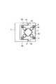
図1〜図3は本発明の実施形態に係る転写装置の全体的構成を例示するものであって、図1,図2において、符号1は転写装置、3は本体フレームである。本体フレーム3は、図1に示すように、側面視した場合の形状は概ねL字型をしており、下部側にベースフレームとしての四角形状の下部フレーム7が一体的に取り付けられている。下部フレーム7の4隅には、それぞれタイバー9が本体フレーム3の垂直部と平行に立設され、タイバー9の上端には、駆動手段を支持するための支持フレームとしての四角形状の上部フレーム5が取り付けられている。タイバー9には、前記上部フレーム5と下部フレーム7との間において、四角形状の可動体19がタイバー9に沿う方向すなわち上下に移動自在に遊嵌されている。
1 to 3 exemplify an overall configuration of a transfer apparatus according to an embodiment of the present invention. In FIGS. 1 and 2, reference numeral 1 denotes a transfer apparatus, and 3 denotes a main body frame. As shown in FIG. 1, the
本体フレーム3の上部は、上部フレーム5及び可動体19の左右両側面における前後方向のほぼ半分(中間)の位置に達するように前方(図1において右方)に突出し、その先端には上下に伸びるリニアガイド(案内手段)21が取り付けられている。上部フレーム5と可動体19の左右両側面には、リニアガイド21に係合して、例えば零クリアランスの状態で上下に精密に案内移動されるスライダ23,24が取り付けられている。
The upper part of the
上記説明より理解されるように、前記本体フレーム3は、前記下部フレーム(ベースフレーム)7を支持するフレーム支持部3Aを一端側(下端側)に備えることにより、側面視したときに、図1に示すように概ねL字形を呈するものである。そして、前記本体フレーム3の他端側(上端側)の左右両側(図1において紙面に垂直な方向の両側)に、前記リニアガイド21を備えたガイドフレーム3Bを前方に突出して備えることにより、上端側(他端側)に凹部を形成した構成である。
As understood from the above description, the
そして、前記上部フレーム5及び前記可動体19は、図3に示すように、本体フレーム3における左右の前記ガイドフレーム3Bの間に配置してあり、前記上部フレーム5,可動体19に備えた前記スライダ23,24は、上部フレーム5,可動体19の前後方向(図1,図3において左右方向)及び左右方向(図1において紙面に垂直な方向、図3において上下方向)の中心を中心として対称的な位置において前記リニアガイド21に移動可能に係合してある。なお、図1には、前記リニアガイド21は、前記スライダ23,24に共通化してあるが、前記スライダ23,24にそれぞれ対応したリニアガイドを別個に設けることも可能である。しかし、加工の容易性、互いの平行度の加工精度を考慮すると、スライダ23,24に対してリニアガイド21を共通に設けることが望ましいものである。
The
ここに、上部フレーム5は、タイバー9を介して下部フレーム7及び本体フレーム3に固定されているが、後述する型の押し付け力や温度変化等によりタイバー9が伸縮したとき、上部フレーム5の上下動を許すと共に、タイバー9の曲がりや伸縮によって生じるタイバー9と垂直な面内における上部フレーム5の位置ずれ(横ずれ)を防止するために、上記リニアガイド21とスライダ23が設けられている。これは、上部フレーム5の位置ずれ(横ずれ)をより確実に防止するためのものであり、上部フレーム5は、本体フレーム3から切り離し、タイバー9により下部フレーム7に連結固定するのみでもよい。
Here, the
可動体19は、上記のようにタイバー9には遊嵌されているため、リニアガイド21とスライダ24により上下方向(テーブル11の面に対し垂直方向)への移動を精密に案内される。
Since the
上記リニアガイド21及びスライダ23,24は、上部フレーム5及び可動体19自体の温度変化による位置ずれ(横ずれ)を防止するため、上部フレーム5及び可動体19の前後左右の中心に対して対称の位置に配置することが好ましい。
The
下部フレーム7の上面中央には、上に向かって垂直に伸びる固定台10が取り付けられている。固定台10の上には、図2に示すように、X,Yテーブル等のX,Y方向(前後左右方向)へ移動可能かつ微調整して位置決め可能な可動テーブル11が設けられ、この可動テーブル11の上には、被成形品13を支持する支持台15が設けられている。なお、可動テーブル11は、リニアガイドとスライダにより案内され、サーボモータにより駆動されるもので、公知の構成であるため、詳述を避ける。
A
被成形品13は、例えば、シリコン、ガラス、セラミック等の適宜な材料よりなる基板の上面に紫外線硬化樹脂等からなる被成形層(図示せず)を数10nm〜数μmの厚さに塗布した薄膜を備えた構成である。なお、この上記被成形層は、熱可塑性樹脂よりなるレジストを用いる場合もあるため、支持台15には、上記被成形層を加熱軟化させて成形を容易にするためのヒータのような加熱手段(図示せず)を内蔵させてもよい。
For the molded product 13, for example, a molded layer (not shown) made of an ultraviolet curable resin or the like is applied to the upper surface of a substrate made of an appropriate material such as silicon, glass, or ceramic to a thickness of several tens nm to several μm. It is the structure provided with the thin film. Since the molded layer may be made of a resist made of a thermoplastic resin, the
図2に示すように、可動体19の下面中央(前記ベースフレームに対向した対向面の中央)には、ロードセル46を介して旋回台47が可動体19の下面中央を中心として旋回可能かつ所定の角度位置に固定可能に取り付けられている。この旋回台47には、ジンバル機構45を介して型支持プレート43が取り付けられ、この型支持プレート43に型41が着脱可能に装着される。
As shown in FIG. 2, at the center of the lower surface of the movable body 19 (the center of the opposite surface facing the base frame), a
ジンバル機構45は、型41の型表面(図2において下面)中央を中心とする球面を有し、詳細な図示は省略するが、この球面を空気軸受で支持し、型41を上記型表面の中央を中心として自在に傾動可能にすると共に、空気軸受を負圧にして型41の姿勢を不動状態に固定可能な構成となっている。
The
型41は、型表面(図2において下面)にリソグラフィ技術を用いて微細な凹凸のパターンが形成されており、この実施形態においては紫外線を透過し易い透明の石英ガラスからなっている。
The
上記型支持プレート43、ジンバル機構45、旋回台47及びロードセル46は、いずれも中央に貫通穴43A等を有し、可動体19には、紫外線光源(UV発生装置)42から光ファイバ42A及び反射ミラー42Bを介して紫外線を上記貫通穴から型41の背面へ導く貫通穴42Cが設けられている。すなわち導光路(UV路)が備えられている。なお、UV発生装置42は、可動体19の側方で可動体19に保持されている。
The
前記導光路は、UV発生装置42から与えられるUVを、UVが透過可能な材質で形成された前記転写用の型41を通して、テーブル11に搭載された被成形材料(被成形品)に照射するためのものであり、たとえば、UV発生装置42から与えられるUV(紫外線)を水平方向に導く第1の導光路と、この第1の導光路を進行するUVを垂直方向であるジンバル機構45の中心軸方向に偏向する反射ミラー42Bと、この反射ミラー42Bで反射されたUVを型保持体205に向けて導くよう前記第1および第2のジンバル部材201、203に形成された貫通孔43Aからなる第2の導光路とにより形成されている。なお、前記第1の導光路の反射ミラー42B側の部位は前記可動体19内に形成され、前記第1の導光路のUV発生装置42側の部位は、光ファイバー42Aで構成されている。また、反射ミラー42Bは、前記第1の導光路の端部側(UV発生装置42とは反対側;前記第2の導光路の上側)に設けられている。
The light guide path irradiates the material to be molded (molded product) mounted on the table 11 through the
支持フレームとしての前記上部フレーム5には、前記可動体19を移動するための駆動手段の一例としてのサーボモータ33が装着支持されている。サーボモータ33の出力軸35は、軸受29により上部フレーム5に回転のみ自在に取り付けられた中空軸31に連結され、中空軸31の下端には、ボールネジ機構25を構成するボールネジナット26が取り付けられている。このボールネジナット26には、可動体19の前後左右の中央部(中心)に垂直に取り付け固定されたボールネジ軸27が係合し、可動体19を所定の速度及びトルクで上下に移動させるようになっている。なお、参照符号33Aはサーボモータ33の回転位置を検出するロータリーエンコーダである。
A
上部フレーム5には、バランス取り手段の一例としてのバランスシリンダ50が、図3に示すように、可動体19の中心を中心として対称な位置に複数設けられている。これらのバランスシリンダ50のピストンロッド52は、それぞれ可動体19に連結され、重力による可動体19の下向きの荷重を相殺するようになっている。
The
可動体19の下面には、型支持プレート43等を囲むリング状の上カバー54が取り付けられている。他方、下部フレーム7側には、下端を固定台10の周面に移動可能に係合され、上端を上記上カバー54の下端に当接可能に形成されて可動テーブル11等を囲む同じくリング状の下カバー56が取り付けられている。この下カバー56は、下部フレーム7に取り付けられた上下動用アクチュエータの一例としての複数のシリンダ58により上下に移動され、上カバー54とにより、型支持プレート43及び可動テーブル11の周囲に開閉可能な成形室(減圧成形室)60を形成するようになっている。
A ring-shaped
次いでこの転写装置の作用について説明する。上下動用アクチュエータとしてのシリンダ58により下カバー56を下降させて成形室60を開き、型41を型支持プレート43に取り付け、型41の中央を中心とする水平な回転方向の取付角度(型の方向性)を旋回台47により微調整する。なお、この型41の取付角度調整は、型取付時のみでなく、マークを用いた公知の位置合わせ手段により、支持台15上にセットされた被成形品13に合わせてその都度、自動的に微調整するようにしてもよい。
Next, the operation of this transfer device will be described. The
上記のように型41をセットした後、上面に紫外線硬化樹脂からなる被成形層を塗布した被成形品13を支持台15上にセットする。
After the
次いでシリンダ58により下カバー56を上昇させて成形室60を閉じ、サーボモータ33のトルクを比較的小さな値に設定した状態で可動体19を下降させて型41を被成形品13に接近移動し、型41を被成形品13の上面に比較的小さな押し付け力で押圧する。
Next, the
このとき、可動体19は、左右両側方に配置されたリニアガイド21及びスライダ24により、移動方向に対して直交する方向への位置ずれ(横ずれ)をより小さく抑えられて下降し、被成形品13の所定位置に向けて押し付けられる。また、このとき、可動体19は、バランスシリンダ50により重力による下向きの荷重を相殺されているため、サーボモータ33はより小さなトルクで作動可能であり、トルク及び速度をより正確に制御されて下降する。
At this time, the
型41が被成形品13に押し付けられる際、両者の当接面(接触面)の平行度にずれがあると、型41はジンバル機構45により傾動自在に支持されているため、被成形品13の上面に倣って型41の全面が均一な面圧で押し付けられる。このとき、ジンバル機構45は、型41の型表面(図2において下面)中央を中心とする球面により、型表面の中央を中心として傾動するため、横方向(水平方向)の位置ずれを生じない。
When the
上記押し付け力は、ロードセル46により検出され、サーボモータ33にフィードバックされて所定の値に保たれる。このときにも、可動体19の荷重は、バランスシリンダ50により相殺され、サーボモータ33のトルクはより小さな値であるため、トルク制御がより正確に行われる。
The pressing force is detected by the
こうして比較的小さな押し付け力による押し付けが完了したところで、ジンバル機構45の空気軸受を負圧にして型41の姿勢を不動状態に固定した後、サーボモータ33のトルクを増加させる。このトルク増加により型41は、被成形品13の上面に塗布された紫外線硬化樹脂からなる被成形層に強く押し付けられ、型41の表面に形成された微細な凹凸のパターンを被成形品13の被成形層に転写する。
When pressing with a relatively small pressing force is completed in this manner, the air bearing of the
この型41の強い押し付け力により、タイバー9は極くわずかではあるが伸び、上部フレーム5を上方向へ変位させる。この上部フレーム5の変位はリニアガイド21とスライダ23により吸収され、本体フレーム3の上部を図1において左方へ反らせるような不具合は生じない。そこで、型41の押し付けに伴う型41の移動方向に対して直交する方向の位置ずれ(横ずれ)が抑えられる。
Due to the strong pressing force of the
また、上部フレーム5は、上記リニアガイド21とスライダ23により支持されているため、複数のタイバー9の伸びに差が生じるような場合にも、上部フレーム5の位置ずれ(横ずれ)は小さく抑えられ、型41の位置ずれ(横ずれ)を小さく抑える。
Further, since the
なお、このタイバー9の伸びの差は、型41の押し付け力が比較的小さい場合には、極めてわずかであるため、上記リニアガイド21とスライダ23による上部フレーム5の案内手段は省略してもよい。
The difference in elongation of the
上記転写の後、紫外線光源42から光ファイバ42A及び反射ミラー42B等よりなる導光路を通して紫外線を型41の背面へ所定時間照射する。型41の背面へ照射された紫外線は、型41が透明の石英ガラスからなっているため、これを透過して被成形品13の上面に塗布された紫外線硬化樹脂からなる被成形層に照射され、この被成形層を硬化させる。
After the transfer, the back surface of the
こうして被成形層を硬化させた後、型41の姿勢を固定したままサーボモータ33により可動体19を上昇させて型41を被成形品13から離す。次いでシリンダ58により下カバー56を下降させて成形室60を開き、被成形品13を取り出して一連の転写動作を終了する。
After the molding layer is cured in this way, the
図4〜図6は、前記ジンバル機構45の部分の詳細を示す。
4 to 6 show details of the
図4はジンバル機構45の垂直方向縦断面図、図5は図4におけるZ矢視図、図6は図4のB−B線矢視図である。
4 is a vertical sectional view in the vertical direction of the
図4において、それぞれ中心部に貫通孔を備えて、凸球面部を有すると共にジンバル機構45を構成している下側ジンバル部材201と凹球面部を有すると共にジンバル機構45を構成している上側ジンバル部材203が対接配置されている。下側ジンバル部材201の下面には断熱材207を介して型保持体205が固定されている。同型保持体205の下面には型41が取り付けられている。またその内部にはヒータ209が内蔵されている。また内部にヒータ209に加え、冷却装置(図示せず)を内蔵することも可能である。
In FIG. 4, a
上側ジンバル部材203には前記対接面に開口する吸引用管路211が形成され、真空引き装置(負圧発生手段)215へ真空度調整装置(負圧調整手段)217を介して接続されている。この吸引用管路211の詳細が図6に例示されている。さらに、上側ジンバル部材203には浮上用管路213が設けられており、同管路213には圧縮エアー供給源からラインL1を通り圧縮エアーが下側ジンバル部材201の凸球面部に隣接して形成された張出し部の傾斜面219(浮上面)に噴射するようになっている。
The
より詳細には、前記傾斜面219は、図4に示すように、下側ジンバル部材201の軸心に対して上側が離反するように傾斜した傾斜面又は上部側が大径となるテーパ面に形成してある。そして、前記浮上用管路213のエアー噴出孔は、前記傾斜面219に対向して上側ジンバル部材203に形成した傾斜面又はテーパ面に開口してある。
More specifically, as shown in FIG. 4, the
なお、参照符号218は調整ライナであって、傾斜面219と下側ジンバル部材201の対向面との間隔を調整するものである。
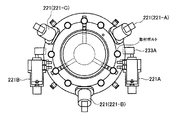
参照符号221は、ピエゾハンマーであってそのフレーム221Fは上側ジンバル部材203の下方傾斜面Sの周囲3ヶ所に均等配置して取り付けられる。図示のように、ピエゾハンマー221は、下側ジンバル部材201と上側ジンバル部材203との間に設けられていると共に、エアーシリンダ223のロッドに大きい慣性体227と先端部にハンマー231を取り付けた小さい慣性体225を有し、両慣性体の間にはピエゾ(圧電)素子229が接続結合されている。従って、ピエゾ素子229に所定のパルス状電圧を与えることにより、両慣性体の慣性の差に基づいてハンマー231が瞬時に下側ジンバル部材201の前記傾斜面に配置してある硬質材の埋込みブロック233を打つようになっている。これにより下側ジンバル部材201の傾斜面219がハンマー231により軸方向に変位するとその分だけエアーシリンダ223によりピエゾ素子229及び両慣性体が変位するようになっている。このような構成によりピエゾハンマー221は比較的少ない積層によるピエゾ素子であっても大きなストロークを移動可能である。
上側ジンバル部材203の上面には回動部材235が固定されており、同回動側部材235の内周側には回転軸受237を介して内側固定部材239が配設されている。さらに、内側固定部材239の上面にはプレート241が取り付け固定されている。前記プレート241及び内側固定部材239にはラインL2を介して圧縮エアーを導入する管路243が形成されている。この圧縮エアーは図示の如く回動部材235を静圧的に浮上させている。
A
図5に示されているように、回動部材235は一対のピエゾハンマー221A、221Bにより時計方向及び反時計方向に回動されることが可能である。なお、ピエゾハンマー221A、221Bはそのフレームがプレート241に固定されている。
As shown in FIG. 5, the rotating
なお、前記ピエゾハンマー221、221A、221Bに代えて、圧電素子を積層した所謂、ピエゾアクチュエータを用いることも可能である。その場合にはピエゾハンマーとは異なり、ピエゾアクチュエータの先端部位置を電気的に保存することが可能でありジンバル機構の姿勢を再現することが可能である。すなわち、ピエゾハンマー221の代わりにピエゾアクチュエータ(図示せず)を当該位置に配置した場合には、その各ピエゾアクチュエータヘの指令電気信号を制御することにより3つのピエゾアクチュエータ自体によって下側ジンバル部材201の姿勢を固定し、保持することが可能である。また、一旦固定し保持したときの各ピエゾアクチュエータヘの指令電気信号の値をメモリに保存しておくことにより、いつでもその保存されている値を読み出すことで下側ジンバル部材201の姿勢を再現することが可能である。
In place of the
なお、このピゾアクチュエータの場合、成形動作中(離形も含め)常時、下側ジンバル部材201を所定の姿勢に固定保持することも可能であるし、後述するピエゾハンマーのように、テーブルに接近した所定位置で第1のジンバル部材201をフリー状態とすることも可能である。
In the case of this piezo actuator, the
図4において、プレート241の上面にはロードセル46が設けられている。参照符号46Aは信号取出し用端子である。可動体19の内部には、図2で説明したように、紫外線発生装置(UV発生装置)42から紫外線強度調整装置(UV強度調整装置)および紫外線照射時間調整装置(UV照射時間調整装置)255を介して光ファイバ42Aの束がレンズ系(可動体19に設けられたレンズ系)253に導かれ、ここで均一な紫外線分布に形成され反射ミラー42Bに照射されるようになっている。同ミラー42Bで反射された紫外線はシール用のガラス材251を経てジンバル機構45の中心軸axに同心状に形成された貫通孔43Aを通って下方に向かうようになっている。紫外線硬化形の樹脂を被成形材料とする場合は、前記型保持体205及び型41は石英などの紫外線透過が可能な材料により形成されることは当然である。また、その場合には前記ヒータ209は不要である。
In FIG. 4, a
なお、参照符号261は下側ジンバル部材201の貫通孔内周面に形成したネジ部(UV反射抑制手段の例であるネジ部)である。貫通孔43A上方からの紫外線は完全に平行ではないためある程度広がりを有する。従って、下方へ向かう紫外線が特に下側ジンバル部材201の貫通孔内周面にて反射しながら型41を通過すると当該紫外線の分布が不均一となるのでこれを避けるため、前記ネジ部261のネジ面にて下方への反射を阻止するものである。その場合、当該ネジ面を反射率の少ない材料でコーティングしておくことが好ましい。なお、前記反射抑制手段として、UV吸収機能を有する材料を前記貫通孔43Aの内周面に塗布またはコーティングした構成にしてもよい。
上述した貫通孔43A及びレンズ系253、紫外線発生装置42等は被成形材料である樹脂が紫外線硬化形の場合に利用されるが、紫外線硬化形樹脂を使用しない場合にはこれら貫通孔43A及びレンズ系253、紫外線発生装置42等はなくてもよい。
The above-described through-
上述のピエゾハンマー221及びピエゾハンマー221A、221Bはそれぞれオプションとして設けることができる。即ち、ジンバル機構45の旋回、回動をさせる必要がない場合は前記回動部材235、内側固定部材239及びピエゾハンマー221A、221Bを省略することが可能である。また、3つのピエゾハンマー221による下側ジンバル部材201の姿勢調整を行なわない場合はこのピエゾハンマー221を省略することが可能である。
The
以下、前記ピエゾハンマー221及び前記回動部材235、内側固定部材239及びピエゾハンマー221A、221Bを装備していない場合の動作について説明する。
Hereinafter, an operation when the
この場合には、被成形品は、典型的には、CD、DVDなどのように円周上に微細な凹凸を形成されたもので、中心点が一致しておればその回転方向位置の影響を受けない被成形品が好適である。可動テーブル11上に配置された基板の中心をジンバル機構45の中心軸axと一致するように当該テーブル11をX,Y方向に位置決めする。可動体19を下降させる際には、ジンバル機構の吸引力を最大にして下側ジンバル部材201を上側ジンバル部材203に吸着した状態とする。
In this case, the molded article is typically formed with fine irregularities on the circumference such as CD, DVD, etc. If the center points coincide, the influence of the rotational direction position A molded product that is not subjected to heat treatment is preferred. The table 11 is positioned in the X and Y directions so that the center of the substrate disposed on the movable table 11 coincides with the central axis ax of the
この状態で、型41が基板上の樹脂に接触する直前の所定位置まで降下したとき、下降速度を低速にすると共に真空引きの吸引力を弱め、下側ジンバル部材201をフリーな状態にして成形圧力をゆっくり与える。即ち、下側ジンバル部材201に取り付け固定されている型保持体205及び型41は下側ジンバル部材201と共に前記テーブル上面に配置された基板上の樹脂を下方へ押し付けつつ最終的には基板と平行な姿勢に倣うようになっている。その場合ジンバル機構45の凸及び凹の球面中心がジンバル機構の中心軸ax上で型の下端面に一致するように配置されているのでこの押圧成形過程では水平方向のずれが生じない。
In this state, when the
ところで、前述のように真空引きの吸引力を弱めて下側ジンバル部材201をフリーな状態にするとき、上側ジンバル部材203の凹球面部に開口したエアー噴出口(図示省略)から下側ジンバル部材201に向けて少量のエアーを噴出する構成とすることが望ましい。このような構成とすることにより、上側ジンバル部材203と下側ジンバル部材201との間の摩擦抵抗がより小さくなり、下側ジンバル部材201をより軽く円滑に動かすことができ、型41の転写面を基板に対して平行にすることが容易であって、基板上の樹脂に対する押圧がより正確に行われるようになるものである。
When the
また、図6に示した複数の吸引用管路211を個別に、又は適宜の複数組み毎にグループ化して、上側ジンバル部材203の凹球面部に形成された複数の環状溝の適数本に選択的に吸引力を作用するようにする。例えば小さな真空度での吸引力の場合には例えば奇数番目の環状溝あるいは少数の環状溝に吸引力を作用し、大きな真空度での吸引力の場合には多数の又は全ての環状溝に吸引力を作用するようにする。
Further, the plurality of
すなわち、吸引力を作用する環状溝の本数を選択する構成(各吸引用管路211を個別にあるいはグループ毎に、真空引き装置に対してバルブ等によって連通遮断自在な構成)とすることにより、真空引きによる吸引力の調整を行うことができるものである。なお、より細かくグループ分けすれば、さらに微妙な真空度の調整ができるものである。
That is, by adopting a configuration for selecting the number of annular grooves that act on the suction force (a configuration in which each
なお、前記型41が基板上の樹脂に接触する直前の所定位置の検出のためにサーボモータ33に結合されているロータリーエンコーダ33Aの信号を利用するが、たとえば、テーブル11または型保持体205上に、電気的な導通・非導通を行なわせる部材を設けて検出することも可能である。
Note that the signal of the
また、オプションとしてピエゾハンマー221を装着した場合、このピエゾハンマー221を機能させるのは、例えば、次のような場合である。即ち、基板上に樹脂を供給する前に、ジンバル機構45を前述と同様に、吸着状態で下降し、型41を基板に押し当てて接触させる。このときその接触状態が完全に平行でなく不均一である場合、吸引力を弱めた状態でその不均一な状態を修正するために3つのピエゾハンマー221に適宜の数の電圧パルスを与えて修正を行なう。このように、予め微調整を行うことにより均一状態となったときにジンバル機構を吸着状態に戻したのち、成形動作を開始する。また、成形品の成形後、型を樹脂から離形する場合にピエゾハンマー221を高い周波数で振動させながら上方へ引き上げると離形動作をスムーズに行なうことが可能である。この場合、振動の振幅は超音波等に比べ格段に小さいので離形中に成形された樹脂を損傷することもない。
Further, when the
その場合、ハンマーの回数は1回又は複数回を短時間で、すなわち高い周波数で与えることが可能である。 In that case, the number of hammers can be given one or more times in a short time, that is, at a high frequency.
一方、ジンバル機構45を旋回、回動させるための一対のピエゾハンマー221A、221Bを備える場合には、このピエゾハンマーを機能させるのは例えば次のような場合である。即ち、基板がテーブル上で、X,Y方向に一致せず回転成分を有する場合であって、且つ中心点が一致していてもその回転方向位置の影響を受けるような被成形品の場合である。この場合にはその回転方向位置即ち、角度を予め測定しておけば、その値に対応する電圧パルスをピエゾハンマー221A、221Bに与えてジンバル機構45を旋回した状態で吸着させるのである。
On the other hand, when a pair of
なお、前記角度及び平行度不均一の測定用として、可動テーブル上面、基板、型保持体の下面等にマーキングを設けてこれらマーキングを物理的(例えば光学的、電磁気的)に検出し前記回転方向位置や不均一性を算出することが可能である。 For measurement of unevenness of the angle and parallelism, markings are provided on the upper surface of the movable table, the substrate, the lower surface of the mold holder, etc., and these markings are detected physically (for example, optically and electromagnetically) and the rotational direction is detected. It is possible to calculate the position and non-uniformity.
ところで、前記可動体19は前記リニアガイド21に案内されて垂直に上下動するものの、可動テーブル11上に載置された被成形品13の上面と型41の下面との関係が相対的に僅かに傾斜した関係にあると、前述したように、ジンバル機構45を介して型41が被成形品13の上面に倣って容易に傾斜し、型41の下面(転写面)と被成形品13の上面(被転写面)とが平行になって転写が行われる。
By the way, although the
前記ピエゾアクチュエータを用いてジンバル機構の姿勢を制御するときは以下のような方法を用いる。 When controlling the attitude of the gimbal mechanism using the piezo actuator, the following method is used.
図7にジンバル機構にピエゾアクチュエータを取り付けた一実施例を示す。 FIG. 7 shows an embodiment in which a piezo actuator is attached to the gimbal mechanism.
ここでは3本のピエゾアクチュエータを120度ずつ位相をずらせて等間隔に配置し、アクチュエータの変位する方向とジンバル機構の側面が垂直になるように取り付けている。3本のアクチュエータの取り付け位置をそれぞれP1,P2,P3とする。各ピエゾアクチュエータは変位量ゼロの平衡状態にあるとき、型板は水平状態にあるものとする。 Here, three piezo actuators are arranged at equal intervals with a phase difference of 120 degrees, and are attached so that the direction in which the actuator is displaced and the side surface of the gimbal mechanism are perpendicular. The attachment positions of the three actuators are P1, P2, and P3, respectively. When each piezo actuator is in an equilibrium state with zero displacement, the template is assumed to be in a horizontal state.
図7に示したようにジンバル機構の回転中心O(図4の型板41の下面の中心点CP)を原点としたX−Y−Z座標系を用いたとき、平衡状態におけるP1,P2,P3の各点におけるピエゾアクチュエータとジンバル機構側面との接点の座標値は次のようになる。

ここでrはP1,P2,P3を結ぶ円のピッチサークル半径、hは型板下面からP1,P2,P3で作られる水平面までの高さを表している。 Here, r represents the pitch circle radius of the circle connecting P1, P2, and P3, and h represents the height from the lower surface of the template to the horizontal plane formed by P1, P2, and P3.
ジンバルの姿勢を変えて型板下面の傾きを微調整するには、各ピエゾアクチュエータに電圧を加えて変位させる必要がある。 In order to finely adjust the inclination of the lower surface of the template by changing the posture of the gimbal, it is necessary to apply a voltage to each piezo actuator and displace it.
しかし、ジンバル機構との関係で幾何学的な制約条件があるため、各アクチュエータに対してはお互いに関連をもった変位指令を与える必要がある。 However, since there is a geometric constraint in relation to the gimbal mechanism, it is necessary to give displacement commands having relations to each actuator.
図8に示したように型板下面の単位法線ベクトルの垂直軸(Z軸)に対する傾き角をΦとし、この法線のX−Y平面への射影をρ、この射影のX−Y平面における偏角をζとすると、ρ=sinΦとなる。型板を希望する姿勢に制御する際、このρとζを指定して傾きを指示するものとすると、各ピエゾアクチュエータに対して、次のように120度位相のずれた変位を指令すると、希望する姿勢が得られる。ここでΔ1,Δ2,Δ3は各ピエゾアクチュエータの平衡状態からの変位量を表している。
この値に比例した電圧V1,V2,V3を各微調整用アクチュエータ221−A,221−B,221−Cに加えることにより型に対して必要な微小回転(微小揺動)を与えることができる。なお、前記演算は、制御装置において行われるものである。 By applying voltages V1, V2, and V3 proportional to these values to the fine-adjustment actuators 221-A, 221-B, and 221-C, the necessary minute rotation (minute oscillation) can be given to the mold. . The calculation is performed in the control device.
本発明は、前述したごとき実施形態のみに限るものではなく、適宜の変更を行うことにより、その他の形態で実施可能である。すなわち、
(A)被成形層は、上記紫外線硬化樹脂、熱可塑性樹脂のほか、いずれのものでもよい。被成形層の材料に応じてその軟化及び/又は硬化手段を選定することができる。
The present invention is not limited to the embodiment described above, and can be implemented in other forms by making appropriate changes. That is,
(A) The layer to be molded may be any of the above ultraviolet curable resin and thermoplastic resin. The softening and / or curing means can be selected according to the material of the molding layer.
(B)型41を下部フレーム7側にセットし、被成形品13を可動体19側に取り付けるようにしてもよい。このとき、被成形層の軟化及び/又は硬化手段も合わせて変更する。
(B) The
(C)ジンバル機構45は、被成形品13がX及び/又はY方向へ移動しない場合には、被成形品13を装置する側に配置してもよく、この場合、及び型41を下部フレーム7側にセットする場合、ジンバル機構45は下部フレーム7側に取り付けてもよい。
(C) If the molded product 13 does not move in the X and / or Y direction, the
(D)図1,図2に示した構成を上下逆にすることや、横にすることも可能である。すなわち、前記説明においては縦型の構成の場合について例示したが、縦型であって上下逆の構成や横型の構成とすることも可能であり、種々の構成を採用することができる。 (D) The configuration shown in FIGS. 1 and 2 can be turned upside down or horizontally. That is, in the above description, the case of the vertical configuration is exemplified, but the vertical configuration may be reversed upside down or the horizontal configuration, and various configurations can be adopted.
(E)前述した実施形態例では、テーブルが下方に配置され、ジンバル機構および可動体は上方に配置される構成としてあるが、これらを上下逆に配置されるようにしてもよい。このように上下を逆に配置した場合には、第1のジンバル部材には重力により常時下方への力が作用するので、その下にある第2のジンバル部材への吸引または吸着カは、図4の構成の場合の配置に比べ少なくすることが可能であるか、または、当該重力そのものを利用して吸引または吸着力を別途発生させる必要をなくすることも可能となり、その際には圧縮空気による第1のジンバル部材に対する浮上力のみを制御すればよい。 (E) In the above-described embodiment, the table is disposed below and the gimbal mechanism and the movable body are disposed above. However, they may be disposed upside down. When the upper and lower sides are arranged upside down in this way, a downward force is always applied to the first gimbal member due to gravity, so that the suction or suction force to the second gimbal member underneath is shown in FIG. 4 can be reduced compared to the arrangement in the case of the configuration of 4 or it is possible to eliminate the need to separately generate suction or adsorption force using the gravity itself. It is sufficient to control only the levitation force on the first gimbal member.
(F)前述した実施形態例では、下側ジンバル部材201(本発明における第1のジンバル部材に対応する)を上側ジンバル部材203(本発明における第2のジンバル部材に対応する)へ吸引するため真空すなわち減圧を利用する方式としたが、その場合、下方に配置される成形室60を真空引きする構成とするとそれらの減圧が相殺されるので吸引効果が期待できないこととなる。この対策として、たとえば、電磁石や永久磁石を用い前記両ジンバル部材201、203との間に、成形室60での減圧により生じる吸引力より大きな吸引力を発生させるようにしてもよい。
(F) In the embodiment described above, the lower gimbal member 201 (corresponding to the first gimbal member in the present invention) is sucked to the upper gimbal member 203 (corresponding to the second gimbal member in the present invention). In this case, if the
1 転写装置
3 本体フレーム
5 上部フレーム(支持フレーム)
7 下部フレーム(ベースフレーム)
9 タイバー
10 固定台
11 可動テーブル
13 被成形品
15 支持台
19 可動体
21 リニアガイド(案内手段)
23,24 スライダ(案内手段)
25 ボールネジ機構
26 ボールネジナット
27 ボールネジ軸
29 軸受
31 中空軸
33 サーボモータ
35 出力軸
41 型
42 紫外線光源
42A 光ファイバ
42B 反射ミラー
42C,43A 貫通穴
43 型支持プレート
45 ジンバル機構
46 ロードセル
47 旋回台
50 バランスシリンダ(バランス取り手段)
52 ピストンロッド
54 上カバー
56 下カバー
58 シリンダ
60 成形室
201 下側ジンバル部材
203 上側ジンバル部材
205 型保持体
207 断熱材
209 ヒータ
211 吸引用管路
213 浮上用管路
221,221A,221B ピエゾハンマー
235 回動部材
239 内側固定部材
241 プレート
253 レンズ系
255 紫外線強度調整装置および紫外線照射時間調整装置
261 ネジ部
1
7 Lower frame (base frame)
9
23, 24 Slider (guide means)
25
52
Claims (19)
(a)被成形材料を搭載するテーブル、
(b)前記テーブル面に対向して配置された転写用の型を固定保持するUV透過材質からなる型保持体、
(c)前記型保持体を一方の面側に保持すると共に他方の面側に凸球面部を形成してなる第1のジンバル部材、
(d)前記第1のジンバル部材の凸球面部と対接する凹球面部を形成した第2のジンバル部材、
(e)前記第2のジンバル部材を保持し、前記テーブル面に対し垂直方向に進退可能な可動体、
(f)前記可動体を前記垂直方向に進退駆動せしめるサーボモータを含む可動体駆動手段、
(g)前記第1のジンバル部材の姿勢を調整保持するための姿勢調整及び保持手段、
(h)UV発生装置、
(i)前記UV発生装置から与えられるUVを、UVが透過可能な材質で形成された前記転写用の型を通して、前記テーブルに搭載された前記被成形材料に照射するためのUV路。 A transfer device having a gimbal mechanism having a UV light guide formed therein and having the following configuration ;
(A) a table on which the molding material is mounted;
(B) a mold holding body made of a UV transmitting material for fixing and holding a transfer mold arranged facing the table surface;
(C) a first gimbal member that holds the mold holder on one side and forms a convex spherical surface on the other side;
(D) a second gimbal member formed with a concave spherical surface portion in contact with the convex spherical surface portion of the first gimbal member;
(E) a movable body that holds the second gimbal member and can advance and retreat in a direction perpendicular to the table surface;
(F) Movable body drive means including a servomotor that drives the movable body to advance and retreat in the vertical direction;
(G) posture adjustment and holding means for adjusting and holding the posture of the first gimbal member;
(H) UV generator,
(I) A UV path for irradiating the material to be molded mounted on the table with the UV supplied from the UV generator through the transfer mold formed of a material capable of transmitting UV.
前記UV発生装置は、前記可動体の側部に設けられ前記可動体に保持されていることを特徴とするジンバル機構を備えた転写装置。 In the transfer device provided with the gimbal mechanism according to claim 1,
The UV generator is provided on a side of the movable body and is held by the movable body. A transfer apparatus having a gimbal mechanism.
前記UV路は、前記可動体内に形成され前記UV発生装置から与えられるUVを水平方向に導く第1の導光路と、前記第1の導光路の端部側に設けられ前記第1の導光路を進行するUVを垂直方向である前記ジンバル機構の中心軸方向に偏向する反射ミラーと、前記反射ミラーで反射されたUVを前記型保持体に向けて導くよう前記第1および第2のジンバル部材に形成された貫通孔からなる第2の導光路とにより構成されていることを特徴とするジンバル機構を備えた転写装置。 In the transfer apparatus provided with the gimbal mechanism according to claim 1 or 2,
The UV path is formed in the movable body and guides UV supplied from the UV generator in the horizontal direction, and the first light guide path is provided on an end side of the first light guide path. A reflecting mirror for deflecting UV traveling in the direction of the central axis of the gimbal mechanism, which is a vertical direction, and the first and second gimbal members for guiding the UV reflected by the reflecting mirror toward the mold holder A transfer device provided with a gimbal mechanism, characterized in that it is constituted by a second light guide path formed of a through-hole formed in.
前記貫通孔の内周面には、前記UVの反射を抑制する反射抑制手段が形成されていることを特徴とするジンバル機構を備えた転写装置。 In the transfer device comprising the gimbal mechanism according to claim 3,
A transfer apparatus provided with a gimbal mechanism, characterized in that reflection suppressing means for suppressing reflection of the UV is formed on an inner peripheral surface of the through hole.
前記反射抑制手段はネジ溝で構成されていることを特徴とするジンバル機構を備えた転写装置。 In the transfer device provided with the gimbal mechanism according to claim 4,
The transfer apparatus having a gimbal mechanism, wherein the reflection suppressing means is formed of a screw groove.
前記反射抑制手段はUV吸収機能を有する材料を前記貫通孔の内周面に塗布またはコーティングして構成されていることを特徴とするジンバル機構を備えた転写装置。 In the transfer device provided with the gimbal mechanism according to claim 4,
The transfer apparatus having a gimbal mechanism, wherein the reflection suppressing means is configured by applying or coating a material having a UV absorption function on the inner peripheral surface of the through hole.
前記UV発生装置が発生したUVを、光ファイバを用いて前記第1の導光路へ導くように構成してあることを特徴とするジンバル機構を備えた転写装置。 In the transfer apparatus provided with the gimbal mechanism according to any one of claims 3 to 6,
A transfer device provided with a gimbal mechanism, wherein the UV generated by the UV generator is guided to the first light guide using an optical fiber.
前記UV発生装置にはUV強度調整装置およびUV照射時間調整装置が設けられていることを特徴とするジンバル機構を備えた転写装置。 In the transfer apparatus provided with the gimbal mechanism according to any one of claims 1 to 7,
A transfer device having a gimbal mechanism, wherein the UV generator is provided with a UV intensity adjusting device and a UV irradiation time adjusting device.
前記姿勢調整及び保持手投は、前記第1のジンバル部材を前記第2のジンバル部材に向けて真空引きするため前記第2のジンバル部材内部に形成され且つ前記凹球面部に開口された真空引き用の管路と同管路に接続された真空引き装置を有する構成であることを特徴とするジンバル機構を備えた転写装置。 In the transfer apparatus provided with the gimbal mechanism according to any one of claims 1 to 8,
The posture adjustment and holding hand throwing is a vacuum suction formed in the second gimbal member and opened in the concave spherical surface portion for evacuating the first gimbal member toward the second gimbal member. A transfer apparatus provided with a gimbal mechanism, characterized in that the apparatus has a vacuum evacuation device connected to the conduit for use.
前記真空引き装置は、真空による吸引力を調整する調整手段を有することを特徴とするジンバル機構を備えた転写装置。 In the transfer device comprising the gimbal mechanism according to claim 9,
The transfer device having a gimbal mechanism, wherein the vacuuming device has an adjusting means for adjusting a suction force by vacuum.
前記真空による吸引力の調整手段は、前記管路に与えられる真空度を調整する構成であることを特徴とするジンバル機構を備えた転写装置。 In the transfer device comprising the gimbal mechanism according to claim 10,
The transfer device having a gimbal mechanism, wherein the vacuum suction force adjusting means adjusts the degree of vacuum applied to the conduit.
前記真空による吸引カの調整手段は、前記真空引き用の管路を増減自在に備えたことにより真空度を調整する構成であることを特徴とするジンバル機構を備えた転写装置。 In the transfer apparatus provided with the gimbal mechanism according to claim 10 or 11,
The transfer device having a gimbal mechanism, wherein the vacuum suction pressure adjusting means is configured to adjust the degree of vacuum by providing the evacuation ducts so as to be increased or decreased.
前記姿勢調整及び保持手段は、さらに、前記第2のジンバル部材から前記第1のジンバル部材向けてエアーを噴射するために、前記第2のジンバル部材内部に形成され且つ前記凹球面部に開口されたエアー噴出用の管路と同管路に接続されたエアー源を有する構成であることを特徴とするジンバル機構を備えた転写装置。 In the transfer device provided with the gimbal mechanism according to any one of claims 1 to 12,
The posture adjusting and holding means is further formed inside the second gimbal member and opened to the concave spherical surface portion for injecting air from the second gimbal member toward the first gimbal member. A transfer apparatus provided with a gimbal mechanism, characterized in that it has a configuration including an air ejection conduit and an air source connected to the conduit.
前記テーブルは水平面内のX、Y方向にそれぞれ移動可能な構成であることを特徴とするジンバル機構を備えた転写装置。 In the transfer device provided with the gimbal mechanism according to any one of claims 1 to 13,
The transfer apparatus having a gimbal mechanism, wherein the table is configured to be movable in X and Y directions in a horizontal plane.
前記第1のジンバル部材は前記凸球面部に隣接して形成された張出し傾斜面を有しており、前記姿勢調整及び保持手投には、さらに、前記張出し傾斜面に圧縮気体を噴射供給する圧縮気体供給管路を前記第2のジンバル部材内部に形成してなる構成であることを特徴とするジンバル機構を備えた転写装置。 In the transfer device provided with the gimbal mechanism according to any one of claims 1 to 14,
The first gimbal member has an overhanging inclined surface formed adjacent to the convex spherical surface portion, and further supplies compressed gas to the overhanging inclined surface for the posture adjustment and holding hand throw. A transfer apparatus provided with a gimbal mechanism, wherein a compressed gas supply line is formed inside the second gimbal member.
前記第2のジンバル部材と前記可動体との間に設けられ、前記可動体に対し前記第2のジンバル部材をその中心軸周りに回転せしめる回動手段を設けたことを特徴とするジンバル機構を備えた転写装置。 In the transfer device provided with the gimbal mechanism according to any one of claims 1 to 15,
A gimbal mechanism provided between the second gimbal member and the movable body, and provided with a rotating means for rotating the second gimbal member around its central axis with respect to the movable body. Equipped transfer device.
前記第1のジンバル部材に形成された凸球面部の球面中心位置は前記第1のジンバル部材の中心軸上であって且つ前記型保持体に固定保持された型の端面に位置している構成であることを特徴とするジンバル機構を備えた転写装置。 In the transfer device provided with the gimbal mechanism according to any one of claims 1 to 16,
The spherical center position of the convex spherical surface portion formed on the first gimbal member is located on the central axis of the first gimbal member and on the end surface of the mold fixedly held by the mold holding body. A transfer device equipped with a gimbal mechanism.
前記型の端部が前記テーブル上の前記被成形材料の上面近傍に接近したことを検知する検出手段を備え、前記検出手段からの信号に応答して前記可動体の速度を遅くする構成であることを特徴とするジンバル機構を備えた転写装置。 In the transfer device provided with the gimbal mechanism according to any one of claims 1 to 17,
The structure includes a detecting unit that detects that the end of the mold has approached the vicinity of the upper surface of the molding material on the table, and reduces the speed of the movable body in response to a signal from the detecting unit. A transfer device provided with a gimbal mechanism characterized by the above.
略L字型のフレームと、
このフレームの下部に一体的に設けられた下部フレームと、
この下部フレームに一端を固着され前記L字型の垂直部に互いに平行に伸びる複数のタイバーと、
これらのタイバーの他端に固着された上部フレームと、
前記下部フレームと上部フレームとの間にあって前記タイバーに沿って移動自在に配置された前記可動体と、
前記フレームから前記可動体の左右両側面のほぼ中央位置まで突出したフレーム突出部と、
この突出部と前記可動体の左右両側面のほぼ中央位置とを前記タイバーに沿って移動自在に係合接続する案内手段と、
前記上部フレームに取り付けられ、前記可動体を前記案内手段に沿って移動させるための前記サーボモータを含む可動体駆動手段とを有することを特徴とするジンバル機構を嘩えた転写装置。 In the transfer apparatus provided with the gimbal mechanism according to any one of claims 1 to 18,
A substantially L-shaped frame;
A lower frame integrally provided at the bottom of the frame;
A plurality of tie bars fixed at one end to the lower frame and extending parallel to the L-shaped vertical portion;
An upper frame fixed to the other end of these tie bars;
The movable body disposed between the lower frame and the upper frame so as to be movable along the tie bar;
A frame protrusion protruding from the frame to a substantially central position on both the left and right side surfaces of the movable body;
Guiding means for movably engaging and connecting the projecting portion and the substantially center positions of the left and right side surfaces of the movable body along the tie bar;
A transfer device having a gimbal mechanism, comprising: a movable body drive unit that is attached to the upper frame and includes the servo motor for moving the movable body along the guide unit.
Priority Applications (5)
| Application Number | Priority Date | Filing Date | Title |
|---|---|---|---|
| JP2005153003A JP4701008B2 (en) | 2005-05-25 | 2005-05-25 | Transfer device with gimbal mechanism |
| TW095118311A TWI307314B (en) | 2005-05-25 | 2006-05-23 | Transcript apparatus |
| DE102006024390.0A DE102006024390B4 (en) | 2005-05-25 | 2006-05-24 | transfer device |
| US11/439,291 US7448862B2 (en) | 2005-05-25 | 2006-05-24 | Transcript apparatus |
| KR1020060046427A KR100764295B1 (en) | 2005-05-25 | 2006-05-24 | Transcript apparatus |
Applications Claiming Priority (1)
| Application Number | Priority Date | Filing Date | Title |
|---|---|---|---|
| JP2005153003A JP4701008B2 (en) | 2005-05-25 | 2005-05-25 | Transfer device with gimbal mechanism |
Publications (3)
| Publication Number | Publication Date |
|---|---|
| JP2006326992A JP2006326992A (en) | 2006-12-07 |
| JP2006326992A5 JP2006326992A5 (en) | 2008-05-08 |
| JP4701008B2 true JP4701008B2 (en) | 2011-06-15 |
Family
ID=37387904
Family Applications (1)
| Application Number | Title | Priority Date | Filing Date |
|---|---|---|---|
| JP2005153003A Active JP4701008B2 (en) | 2005-05-25 | 2005-05-25 | Transfer device with gimbal mechanism |
Country Status (5)
| Country | Link |
|---|---|
| US (1) | US7448862B2 (en) |
| JP (1) | JP4701008B2 (en) |
| KR (1) | KR100764295B1 (en) |
| DE (1) | DE102006024390B4 (en) |
| TW (1) | TWI307314B (en) |
Families Citing this family (5)
| Publication number | Priority date | Publication date | Assignee | Title |
|---|---|---|---|---|
| US7648354B2 (en) * | 2005-04-28 | 2010-01-19 | Toshiba Kikai Kabushiki Kaisha | Transfer apparatus having gimbal mechanism and transfer method using the transfer apparatus |
| JP5517423B2 (en) * | 2008-08-26 | 2014-06-11 | キヤノン株式会社 | Imprint apparatus and imprint method |
| JP5267174B2 (en) * | 2009-02-03 | 2013-08-21 | ソニー株式会社 | Stereolithography apparatus and modeling base |
| JP4597254B1 (en) | 2009-10-16 | 2010-12-15 | 株式会社ユアビジネス | Rotating structure of rotating body |
| CN109501225A (en) * | 2018-12-31 | 2019-03-22 | 焦作飞鸿安全玻璃有限公司 | A kind of injection product surface metal effect processing unit |
Citations (6)
| Publication number | Priority date | Publication date | Assignee | Title |
|---|---|---|---|---|
| JPH11314231A (en) * | 1998-03-06 | 1999-11-16 | Toshiba Corp | Method and apparatus for producing optical part |
| JP2001135634A (en) * | 1999-11-10 | 2001-05-18 | Nippon Telegr & Teleph Corp <Ntt> | Film former |
| JP2002251802A (en) * | 2001-02-23 | 2002-09-06 | Sony Corp | Manufacturing method for disk-like recording medium and metal mold device |
| JP2004291607A (en) * | 2002-05-17 | 2004-10-21 | Konica Minolta Holdings Inc | Method of adjusting mold unit and molding assembly |
| JP2005052841A (en) * | 2003-08-01 | 2005-03-03 | Meisho Kiko Kk | High precision press |
| JP2005533393A (en) * | 2002-07-11 | 2005-11-04 | モレキュラー・インプリンツ・インコーポレーテッド | Imprint lithography process and system |
Family Cites Families (25)
| Publication number | Priority date | Publication date | Assignee | Title |
|---|---|---|---|---|
| FR2151202A5 (en) * | 1971-08-25 | 1973-04-13 | Lunetiers | |
| US4316712A (en) | 1980-11-10 | 1982-02-23 | Medendorp Roger L | Press and actuator therefor |
| US4878826A (en) | 1987-12-07 | 1989-11-07 | Wendt Michael L | Apparatus for thermoforming plastic materials |
| EP0339616B1 (en) * | 1988-04-27 | 1997-01-08 | Dainippon Ink And Chemicals, Inc. | Apparatus for manufacturing optical information recording medium |
| US4969812A (en) | 1989-05-30 | 1990-11-13 | Brown Gaylord W | Fluid pressure operated apparatus for mounting a differential pressure mold on a platen |
| JP3230833B2 (en) | 1992-03-27 | 2001-11-19 | 日立テクノエンジニアリング株式会社 | hot press |
| DE19819761C2 (en) | 1998-05-04 | 2000-05-31 | Jenoptik Jena Gmbh | Device for separating a shaped substrate from an embossing tool |
| DE19925175C1 (en) | 1999-05-27 | 2000-05-25 | Jenoptik Jena Gmbh | Apparatus for transferring microstructures from a tool onto a substrate comprises a measuring system moving between carriers |
| US6364648B1 (en) * | 1999-12-21 | 2002-04-02 | Johnson & Johnson Vision Care, Inc. | Four axis casting fixture |
| US6808443B2 (en) * | 2000-07-01 | 2004-10-26 | Lam Research Corporation | Projected gimbal point drive |
| JP3679767B2 (en) * | 2002-02-26 | 2005-08-03 | キヤノン株式会社 | Stage positioning apparatus, control method therefor, exposure apparatus, and semiconductor device manufacturing method |
| JP3472963B1 (en) | 2002-05-30 | 2003-12-02 | ミカドテクノス株式会社 | Vacuum press for high temperature |
| JP2004034300A (en) | 2002-06-28 | 2004-02-05 | Elionix Kk | Micro-extruder |
| US7070405B2 (en) * | 2002-08-01 | 2006-07-04 | Molecular Imprints, Inc. | Alignment systems for imprint lithography |
| JP3783054B2 (en) * | 2002-10-24 | 2006-06-07 | 独立行政法人産業技術総合研究所 | Active double joint pressure mechanism |
| JP4220282B2 (en) | 2003-03-20 | 2009-02-04 | 株式会社日立製作所 | Nanoprint apparatus and fine structure transfer method |
| JP4340086B2 (en) | 2003-03-20 | 2009-10-07 | 株式会社日立製作所 | Nanoprinting stamper and fine structure transfer method |
| TW568349U (en) | 2003-05-02 | 2003-12-21 | Ind Tech Res Inst | Parallelism adjusting device for nano-transferring |
| JP2004358857A (en) | 2003-06-06 | 2004-12-24 | Meiki Co Ltd | Apparatus for forming resin formed product having fine uneven surface |
| US7150622B2 (en) | 2003-07-09 | 2006-12-19 | Molecular Imprints, Inc. | Systems for magnification and distortion correction for imprint lithography processes |
| JP2005101201A (en) * | 2003-09-24 | 2005-04-14 | Canon Inc | Nano-imprint system |
| US7140861B2 (en) * | 2004-04-27 | 2006-11-28 | Molecular Imprints, Inc. | Compliant hard template for UV imprinting |
| US7059198B2 (en) | 2004-08-17 | 2006-06-13 | Amitkumar N. Dharia | Apparatus to determine ability of plastic material to be shaped by thermoforming process |
| JP4500183B2 (en) | 2005-02-25 | 2010-07-14 | 東芝機械株式会社 | Transfer device |
| JP4700996B2 (en) | 2005-04-19 | 2011-06-15 | 東芝機械株式会社 | Transfer device |
-
2005
- 2005-05-25 JP JP2005153003A patent/JP4701008B2/en active Active
-
2006
- 2006-05-23 TW TW095118311A patent/TWI307314B/en active
- 2006-05-24 DE DE102006024390.0A patent/DE102006024390B4/en active Active
- 2006-05-24 KR KR1020060046427A patent/KR100764295B1/en active IP Right Grant
- 2006-05-24 US US11/439,291 patent/US7448862B2/en not_active Expired - Fee Related
Patent Citations (6)
| Publication number | Priority date | Publication date | Assignee | Title |
|---|---|---|---|---|
| JPH11314231A (en) * | 1998-03-06 | 1999-11-16 | Toshiba Corp | Method and apparatus for producing optical part |
| JP2001135634A (en) * | 1999-11-10 | 2001-05-18 | Nippon Telegr & Teleph Corp <Ntt> | Film former |
| JP2002251802A (en) * | 2001-02-23 | 2002-09-06 | Sony Corp | Manufacturing method for disk-like recording medium and metal mold device |
| JP2004291607A (en) * | 2002-05-17 | 2004-10-21 | Konica Minolta Holdings Inc | Method of adjusting mold unit and molding assembly |
| JP2005533393A (en) * | 2002-07-11 | 2005-11-04 | モレキュラー・インプリンツ・インコーポレーテッド | Imprint lithography process and system |
| JP2005052841A (en) * | 2003-08-01 | 2005-03-03 | Meisho Kiko Kk | High precision press |
Also Published As
| Publication number | Publication date |
|---|---|
| US20060269645A1 (en) | 2006-11-30 |
| JP2006326992A (en) | 2006-12-07 |
| TW200711852A (en) | 2007-04-01 |
| KR20060121743A (en) | 2006-11-29 |
| DE102006024390B4 (en) | 2016-12-29 |
| DE102006024390A1 (en) | 2006-11-30 |
| TWI307314B (en) | 2009-03-11 |
| KR100764295B1 (en) | 2007-10-05 |
| US7448862B2 (en) | 2008-11-11 |
Similar Documents
| Publication | Publication Date | Title |
|---|---|---|
| US8318074B2 (en) | Transfer apparatus having gimbal mechanism and transfer method using the transfer apparatus | |
| JP4500183B2 (en) | Transfer device | |
| US7448865B2 (en) | Transcript apparatus | |
| US7465162B2 (en) | Transcript apparatus | |
| JP4701008B2 (en) | Transfer device with gimbal mechanism | |
| JP2006326992A5 (en) | ||
| JP4732801B2 (en) | Transfer device having gimbal mechanism and transfer method using the same | |
| JP5666082B2 (en) | Transfer device and press device | |
| JP2006326991A5 (en) | ||
| JP4854313B2 (en) | Control device in transfer device | |
| JP4856941B2 (en) | Transfer device with gimbal mechanism and transfer method using the same | |
| JP4729337B2 (en) | Transfer device with gimbal mechanism and transfer method using the same | |
| JP4732800B2 (en) | Transfer device having gimbal mechanism and transfer method using the same | |
| JP5328869B2 (en) | Method of manufacturing a mold for transfer | |
| JP2006305930A5 (en) | ||
| JP2006326980A5 (en) | ||
| JP6761279B2 (en) | Positioning equipment, lithography equipment and article manufacturing method | |
| JP4857050B2 (en) | Transfer device with gimbal mechanism | |
| JP7161309B2 (en) | Stage apparatus, lithographic apparatus, and method of manufacturing article | |
| JP2008000945A (en) | Mold for transcription | |
| JP6882027B2 (en) | Imprint equipment and article manufacturing method | |
| JP5224930B2 (en) | Transfer device | |
| JP2021184441A (en) | Mold, imprint device, and article manufacturing method | |
| JP2012104845A (en) | Transfer device |
Legal Events
| Date | Code | Title | Description |
|---|---|---|---|
| A521 | Request for written amendment filed |
Free format text: JAPANESE INTERMEDIATE CODE: A523 Effective date: 20080326 |
|
| A621 | Written request for application examination |
Free format text: JAPANESE INTERMEDIATE CODE: A621 Effective date: 20080326 |
|
| TRDD | Decision of grant or rejection written | ||
| A01 | Written decision to grant a patent or to grant a registration (utility model) |
Free format text: JAPANESE INTERMEDIATE CODE: A01 Effective date: 20110222 |
|
| A977 | Report on retrieval |
Free format text: JAPANESE INTERMEDIATE CODE: A971007 Effective date: 20110224 |
|
| A61 | First payment of annual fees (during grant procedure) |
Free format text: JAPANESE INTERMEDIATE CODE: A61 Effective date: 20110307 |
|
| R150 | Certificate of patent or registration of utility model |
Ref document number: 4701008 Country of ref document: JP Free format text: JAPANESE INTERMEDIATE CODE: R150 |
|
| S533 | Written request for registration of change of name |
Free format text: JAPANESE INTERMEDIATE CODE: R313533 |
|
| R350 | Written notification of registration of transfer |
Free format text: JAPANESE INTERMEDIATE CODE: R350 |