JP3675254B2 - Method for manufacturing ceramic slurry, ceramic green sheet and multilayer ceramic electronic component - Google Patents
Method for manufacturing ceramic slurry, ceramic green sheet and multilayer ceramic electronic component Download PDFInfo
- Publication number
- JP3675254B2 JP3675254B2 JP28393499A JP28393499A JP3675254B2 JP 3675254 B2 JP3675254 B2 JP 3675254B2 JP 28393499 A JP28393499 A JP 28393499A JP 28393499 A JP28393499 A JP 28393499A JP 3675254 B2 JP3675254 B2 JP 3675254B2
- Authority
- JP
- Japan
- Prior art keywords
- slurry
- ceramic
- dispersion
- mixing
- binder
- Prior art date
- Legal status (The legal status is an assumption and is not a legal conclusion. Google has not performed a legal analysis and makes no representation as to the accuracy of the status listed.)
- Expired - Fee Related
Links
Images

Description
【0001】
【発明の属する技術分野】
本願発明は、積層セラミック電子部品の製造に使用されるセラミックスラリー及びセラミックグリーンシートの製造方法、並びに積層セラミック電子部品の製造方法に関する。
【0002】
【従来の技術】
積層セラミックコンデンサやセラミック多層基板などの積層セラミック電子部品は、通常、セラミックグリーンシートを積層、圧着し、熱処理して、セラミックや電極を焼結させる工程を経て製造されている。
【0003】
例えば、図1に示すように、セラミック素子1中に内部電極2が配設されているとともに、セラミック素子1の両端部に、交互に異なる側の端面に引き出された内部電極2と導通するように一対の外部電極3a,3bが配設された構造を有する積層セラミックコンデンサを製造する場合、通常は、以下のような方法で製造されている。
【0004】
(1)まず、上述のようにして製造したセラミックグリーンシートに容量形成用の内部電極を配設することにより、電極配設シート11(図2)を形成する。
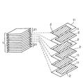
(2)次に、図2に示すように、電極配設シート11を所定枚数積層し、さらにその上下両面側に電極の配設されていないセラミックグリーンシート(外層用シート)21を積層、圧着することにより、各内部電極2の一端側が交互に異なる側の端面に引き出された積層体(積層圧着体)を形成する。
(3)そして、この積層圧着体を所定の条件で焼成してセラミックを焼結させた後、焼成後の積層体(セラミック素子)1(図1)の両端部に導電性ペーストを塗布、焼付けして、内部電極2と導通する外部電極3a,3b(図1)を形成する。
これにより、図1に示すような積層セラミックコンデンサが得られる。
【0005】
また、積層セラミック多層基板などの他の積層セラミック電子部品も、セラミックグリーンシートを積層する工程を経て製造されている。
【0006】
ところで、積層セラミック電子部品の製造に用いられるセラミックグリーンシートは、一般に、セラミック粉末を、分散媒(溶媒)、分散剤、バインダー、可塑剤などと所定の割合で配合し、ビーズミル、ボールミル、アトライタ、ペイントシェーカ、サンドミルなどの媒体型分散機を用いて混合・解砕することにより製造したセラミックスラリーを、ドクターブレード法などの方法により所定の厚さのシートに成形した後、乾燥させることにより製造されている。
【0007】
しかしながら、近年、積層セラミックコンデンサをはじめとする種々の積層セラミック電子部品に対しては、他の電子素子に対するのと同様に、小型化、高性能化が求められるようになっている。
そして、そのためには、積層セラミック電子部品の製造に用いられるセラミックグリーンシートを薄くすることが必要になり、近年は、厚みが10μm以下の極めて薄いセラミックグリーンシートを用いることが必要になりつつある。
【0008】
このように、厚みの薄いセラミックグリーンシートを製造しようとすると、セラミックグリーンシートの製造に用いられるセラミックスラリーとして、セラミック原料粉末が十分に分散しているものを用いることが必要となり、そのためには、セラミック原料粉末として、平均粒径が0.01〜1μmの微粉末のセラミック原料を用いることが必要になる。
【0009】
【発明が解決しようとする課題】
しかしながら、セラミック粉末を、分散媒(溶媒)、分散剤、バインダー、可塑剤などと所定の割合で配合し、ビーズミル、ボールミル、アトライタ、ペイントシェーカー、サンドミルなどの媒体型分散機を用いて混合・解砕する、従来のセラミックスラリーの製造方法では、1μm以下のセラミック微粉末を十分に分散させることは困難で、均一に分散されたセラミックスラリーを得ることができず、厚みが薄く、しかも高品質なセラミックグリーンシートを製造することは困難であるのが実情である。
【0010】
すなわち、上述の従来の方法で製造したセラミックスラリーを用いて製造したセラミックグリーンシートは、(1)表面の円滑性が十分ではない、(2)高密度のものが得られず、引張り強度が不十分である、(3)バインダーや可塑剤などの樹脂の分布が不均一となり、積層後の焼成工程における収縮率が部位によりばらつき、十分な寸法精度が得られない、というような問題点がある。なお、これらの問題点は、高重合度のバインダーを用いる場合に特に顕著になる。
【0011】
また、従来のセラミックスラリーの製造方法では、分散性を向上させるために玉石を充填したボールミルや、ビーズを充填したビーズミルを用いて、強制的な衝突あるいは衝撃力を付与してセラミック粉末を分散させる方法が用いられる場合があるが、その場合、衝突や衝撃による解砕力が大きすぎたり、またそれらの力の制御性が良くないため、セラミック粉末へのダメージが大きくなり、セラミック粉末の結晶性の低下や、比表面積の増加を招き、所望の電気特性を備えた積層セラミック電子部品を得ることができなくなるという問題点がある。
【0012】
また、セラミック粉末を含むスラリーを高圧に加圧して流動させることによりセラミック粉末を分散させる高圧分散の方法が用いられる場合もあるが、高圧分散のみでは、ボールミルやビーズミルなどの媒体型分散法のような強制的な衝突あるいは衝撃力による解砕の方法に比べて解砕力が小さいため、強固に凝集した凝結粒子を十分に解砕することは困難で、十分に分散されたセラミックスラリーを製造することができず、高品質なセラミックグリーンシートを得ることができないという問題点がある。
【0013】
また、セラミック粉末を含むスラリーに高圧を負荷して、微小なオリフィスあるいはノズルから噴出させたスラリーを、硬質材料、例えば、超硬合金、セラミック、ダイヤモンドなどの固体壁に衝突させたり、複数の微小なオリフィスあるいはノズルから噴出させたスラリーどうしを衝突させることにより分散させる方法もあるが、この方法では、上記のタイプの高圧分散方式に比べ、同一のエネルギーをスラリーに負荷した場合、流動するセラミック粉末に負荷する応力は大きくできるが、その均一性が劣るため、強固に凝集した凝結粒子を解砕することはできても、十分に分散されたセラミックスラリーを製造することができず、高品質なセラミックグリーンシートを得ることができないという問題点がある。
【0014】
本願発明は、このような背景に鑑みてなされたものであり、セラミック粉末に過度のダメージを与えることなく、セラミック粉末を均一に分散させることが可能で、セラミック電子部品の製造に用いるのに適したセラミックスラリーを効率よく製造することが可能なセラミックスラリーの製造方法、及びセラミックグリーンシート並びに積層セラミック電子部品の製造方法を提供することを目的とする。
【0015】
【課題を解決するための手段】
上記目的を達成するため、本願発明(請求項1)のセラミックスラリーの製造方法は、
セラミック電子部品の製造に用いられるセラミックスラリーの製造方法において、
平均粒径が0.01〜1μmのセラミック粉末と分散媒とを、100kg/cm2以上の圧力に加圧して噴射し、100m/s以上の速度で硬質材料からなる固体壁に衝突させて、所望の状態までセラミック粉末を解砕して分散させることにより混合、解砕スラリーを得る、衝撃力型高圧分散法による混合・解砕工程と、
前記混合・解砕工程において得た前記混合・解砕スラリーを、100kg/cm2以上の圧力に加圧して、所定の流路を、セラミック粉末に1000Pa以上の最大せん断応力、又は106[1/s]以上の壁面せん断速度を与えることが可能な流速で通過させることにより分散させる、せん断応力型高圧分散法による分散工程と
を具備することを特徴としている。
【0016】
また、本願発明(請求項2)のセラミックスラリーの製造方法は、
セラミック電子部品の製造に用いられるセラミックスラリーの製造方法において、
平均粒径が0.01〜1μmのセラミック粉末と分散媒とを、100kg/cm2以上の圧力に加圧し、それを複数の互いに対向させた噴射口から噴射し、セラミック粉末と分散媒の両者を50m/s以上の速度で互いに衝突させることにより、所望の状態までセラミック粉末を解砕して分散させることにより混合・解砕スラリーを得る、衝撃力型高圧分散法による混合・解砕工程と、
前記混合・解砕工程において得た前記混合・解砕スラリーを、100kg/cm2以上の圧力に加圧して、所定の流路を、セラミック粉末に1000Pa以上の最大せん断応力、又は106[1/s]以上の壁面せん断速度を与えることが可能な流速で通過させることにより分散させる、せん断応力型高圧分散法による分散工程と
を具備することを特徴としている。
【0017】
本願発明(請求項1及び2)のセラミックスラリーの製造方法においては、平均粒径が0.01〜1μmのセラミック粉末と分散媒(溶媒)とを、微小ノズルやオリフィスなどから噴出させて、固体壁に衝突させるかあるいは噴流体どうしを衝突させる衝撃力型高圧分散法により混合・解砕スラリーを得た後、これを高速で微小流路を流動させるせん断応力型高圧分散法で分散させるようにしているので、セラミック粉末が十分に分散された分散スラリーを得ることが可能になる。
すなわち、衝撃力型高圧分散法とせん断応力型高圧分散法を組み合わせてセラミック粉末を分散させることにより、セラミック粉末の結晶性を損なったり、比表面積が過度に大きくなったりすることを抑制しつつ、セラミック粉末を均一に分散させることが可能になり、高品質のセラミックスラリーを製造することが可能になる。
なお、本願発明においては、分散媒として、分散剤、可塑剤、帯電防止剤を含むものを用いることが可能であり、さらに他の添加剤を含むものを用いることも可能である。
【0018】
また、本願発明は、セラミック粉末の平均粒径(電子顕微鏡で求めた平均の一次粒径)が、0.01〜1μmの範囲にある場合に、特に有利に適用されるが、0.01〜1μmの範囲を超える場合にも適用することが可能である。
なお、本願発明において、衝撃力型高圧分散法による混合・解砕を行う場合、セラミック粉末と分散媒とを加圧して噴射させる手段として、微小ノズルや、所定の直径の噴射口を形成したオリフィスなど、種々の手段(機構)を用いることが可能である。
【0019】
また、請求項3のセラミックスラリーの製造方法は、バインダーを添加した状態で、前記衝撃力型高圧分散法による混合・解砕を行うことを特徴としている。
【0020】
バインダーを添加した状態で、混合・解砕工程を実施するようにした場合にも、セラミック粉末に過度のダメージを与えることなく、セラミック粉末を均一に分散させることが可能になり、高品質のセラミックスラリーを製造することが可能になる。
なお、バインダーは分散媒にあらかじめ配合しておいてもよく、セラミック粉末を分散媒に分散させる際に配合してもよく、その添加のタイミングに特別の制約はない。
【0021】
また、本願発明(請求項4)のセラミックスラリーの製造方法は、
セラミック電子部品の製造に用いられるセラミックスラリーの製造方法において、
平均粒径が0.01〜1μmのセラミック粉末と、バインダーを含有していない分散媒とを、100 kg/cm 2 以上の圧力に加圧して噴射し、100 m/s 以上の速度で硬質材料からなる固体壁に衝突させて、所望の状態までセラミック粉末を解砕して分散させることにより混合・解砕スラリーを得る、衝撃力型高圧分散法による混合・解砕工程と、
前記混合・解砕工程において得た前記混合・解砕スラリーにバインダーを添加するバインダー添加工程と、
前記バインダー添加工程でバインダーが添加された前記混合・解砕スラリーを、100 kg/cm 2 以上の圧力に加圧して、所定の流路を、セラミック粉末に1000 Pa 以上の最大せん断応力、又は10 6 [ 1/s ]以上の壁面せん断速度を与えることが可能な流速で通過させることにより分散させる、せん断応力型高圧分散法による分散工程と
を具備することを特徴としている。
【0022】
セラミック粉末と、バインダーを含有していない分散媒とを、衝撃力型高圧分散法により混合・解砕して得た混合・解砕スラリーにバインダーを添加し、せん断応力型高圧分散法により分散させることにより、セラミック粉末がさらによく分散された分散スラリーを得ることができるようになる。
【0023】
すなわち、バインダーは、一部がゲル状になって分散媒中に存在することがあり、そのような状態で衝撃力型高圧分散法によりセラミック粉末を混合・解砕するよりも、バインダーを添加する前にセラミック粉末と分散媒とを衝撃力型高圧分散法により混合・解砕することにより、混合・解砕の効率を向上させることが可能になり、最終的なセラミック粉末の分散性をより向上させることができるようになる。
【0024】
また、請求項5のセラミックスラリーの製造方法は、
セラミック電子部品の製造に用いられるセラミックスラリーの製造方法において、
平均粒径が0.01〜1μ m のセラミック粉末と、バインダーを含有していない分散媒とを、100 kg/cm 2 以上の圧力に加圧し、それを複数の互いに対向させた噴射口から噴射し、セラミック粉末と分散媒の両者を50 m/s 以上の速度で互いに衝突させることにより、所望の状態までセラミック粉末を解砕して分散させることにより混合・解砕スラリーを得る、衝撃力型高圧分散法による混合・解砕工程と、
前記混合・解砕工程において得た前記混合・解砕スラリーにバインダーを添加するバインダー添加工程と、
前記バインダー添加工程でバインダーが添加された前記混合・解砕スラリーを、100 kg/cm 2 以上の圧力に加圧して、所定の流路を、セラミック粉末に1000 Pa 以上の最大せん断応力、又は10 6 [ 1/s ]以上の壁面せん断速度を与えることが可能な流速で通過させることにより分散させる、せん断応力型高圧分散法による分散工程と
を具備することを特徴としている。
【0025】
本願発明(請求項5)のセラミックスラリーの製造方法においても、上記請求項4のセラミックスラリーの製造方法の場合と同様に、セラミック粉末と、バインダーを含有していない分散媒とを、衝撃力型高圧分散法により混合・解砕して得た混合・解砕スラリーにバインダーを添加し、せん断応力型高圧分散法により分散させることにより、セラミック粉末がさらによく分散された分散スラリーを得ることができるようになる。
【0026】
また、本願発明(請求項6)のセラミックスラリーの製造方法は、
セラミック電子部品の製造に用いられるセラミックスラリーの製造方法において、
平均粒径が0.01〜1μmのセラミック粉末と、バインダーを含有していない分散媒とを、前記衝撃力型高圧分散法により混合・解砕して混合・解砕スラリーを得る混合・解砕工程と、
前記混合・解砕工程において得た前記混合・解砕スラリーを、前記せん断応力型高圧分散法により分散させて一次分散スラリーを得る一次分散工程と、
前記一次分散工程において得た前記一次分散スラリーにバインダーを添加し、さらに前記せん断応力型高圧分散法により分散させて二次分散スラリー(最終分散スラリー)を得る二次分散工程と
を具備することを特徴としている。
【0027】
セラミック粉末と、バインダーを含有していない分散媒とを、衝撃力型高圧分散法により混合・解砕して得た混合・解砕スラリーを、せん断応力型高圧分散法により分散させて得た一次分散スラリーにバインダーを添加し、さらにせん断応力型高圧分散法により分散させるようにした場合、セラミック粉末に過度のダメージを与えることなく、セラミック粉末を均一に分散させることが可能になり、高品質のセラミックスラリーを製造することが可能になる。
【0028】
また、本願発明(請求項7)のセラミックスラリーの製造方法は、
セラミック電子部品の製造に用いられるセラミックスラリーの製造方法において、
平均粒径が0.01〜1μmのセラミック粉末と、バインダーを含有していない分散媒とを、前記衝撃力型高圧分散法により混合・解砕して一次混合・解砕スラリーを得る一次混合・解砕工程と、
前記一次混合・解砕工程において得た前記一次混合・解砕スラリーにバインダーを添加し、前記衝撃力型高圧分散法により混合・解砕して二次混合・解砕スラリーを得る二次混合・解砕工程と、
前記二次混合・粉砕工程において得た前記二次混合・解砕スラリーを、前記せん断応力型高圧分散法により分散させて分散スラリーを得る分散工程と
を具備することを特徴としている。
【0029】
セラミック粉末と、バインダーを含有していない分散媒とを、衝撃力型高圧分散法により混合・解砕して得た一次混合・解砕スラリーにバインダーを添加し、再び、衝撃力型高圧分散法により混合・解砕して得た二次混合・解砕スラリーを、せん断応力型高圧分散法で分散させるようにした場合にも、セラミック粉末に過度のダメージを与えることなく、セラミック粉末を均一に分散させることが可能になり、高品質のセラミックスラリーを製造することが可能になる。
【0030】
また、請求項8のセラミックスラリーの製造方法は、前記バインダーとして、溶媒とバインダーとを撹拌混合し、100kg/cm2以上の圧力に加圧して、所定の流路を、1000Pa以上の最大せん断応力、又は106[1/s]以上の壁面せん断速度を与えることが可能な流速で通過させることにより分散させる、せん断応力型高圧分散法により分散させたバインダー溶液を用いることを特徴としている。
【0031】
バインダーとして、溶媒とバインダーとを撹拌混合し、せん断応力型高圧分散法により分散させたバインダー溶液を用いることにより、バインダーを直接添加する場合に生じるようなゲルの発生を抑制、防止して、セラミック粉末の分散性をさらに向上させることが可能になる。
【0032】
また、請求項9のセラミックスラリーの製造方法は、前記バインダーとして、溶媒とバインダーとを撹拌混合したバインダー混合溶液を、40〜100℃で加熱還流させたバインダー溶液を用いることを特徴としている。
【0033】
バインダーとして、溶媒とバインダーとを撹拌混合したバインダー混合溶液を、40〜100℃で加熱還流させたバインダー溶液を用いるようにした場合、バインダーをより確実に溶解させた状態(μmサイズの凝集のない状態)で添加することが可能になり、さらにセラミック粉末の分散性を向上させることが可能になる。
【0034】
また、請求項10のセラミックスラリーの製造方法は、前記分散スラリー(最終分散スラリー)の粘度が0.003〜0.1Pasであることを特徴としている。
【0035】
分散スラリー(最終分散スラリー)の粘度が0.003〜0.1Pasとなるようにした場合、シート状に成形したセラミックグリーンシートを作製する工程で用いるのに適したセラミックスラリーを得ることができるようになり、本願発明をさらに実効あらしめることができる。
【0036】
また、本願発明(請求項11)のセラミックグリーンシートの製造方法は、本願発明(請求項1〜10)の方法により製造されたセラミックスラリーを、所定の基材上にシート状に成形して、厚さが0.1〜10μmのセラミックグリーンシートを形成することを特徴としている。
【0037】
請求項1〜10の方法により製造されたセラミックスラリーにおいては、平均粒径が0.01〜1μmのセラミック粉末が分散媒に十分に分散しており、これをシート状に成形することにより、厚さが薄く(0.1〜10μm)、高品質のセラミックグリーンシートを確実に製造することが可能になる。すなわち、表面の円滑性に優れ、高密度で、引張り強度が大きく、しかも、バインダーや可塑剤などの樹脂の分布が均一な、積層セラミック電子部品の製造に用いるのに適したセラミックグリーンシートを得ることが可能になる。そして、このセラミックグリーンシートを用いて積層セラミック電子部品を製造した場合、所望の特性を有する高品質で信頼性の高い積層セラミック電子部品を得ることが可能になる。
【0038】
また、本願発明(請求項12)の積層セラミック電子部品の製造方法は、本願発明(請求項1〜10)の方法により製造されたセラミックスラリーを用いてセラミックグリーンシートを形成し、該セラミックグリーンシートを卑金属内部電極とともに積層、切断、焼成した後、外部電極を形成することを特徴としている。
【0039】
本願発明の方法により製造されたセラミックスラリーを用いてセラミックグリーンシートを形成し、該セラミックグリーンシートを卑金属内部電極とともに積層、切断、焼成した後、外部電極を形成することにより、所望の特性を有する高品質で信頼性の高い積層セラミック電子部品を得ることが可能になる。
【0040】
【発明の実施の形態】
以下、本願発明の実施の形態を示してその特徴とするところをさらに詳しく説明する。
本願発明を実施するにあたっては、セラミック粉末の種類や具体的な組成に特別の制約はなく、チタン酸バリウム系、チタン酸ストロンチウム系、チタン酸鉛系などの誘電体セラミック粉末、フェライト系などの磁性体セラミック粉末、圧電体セラミック粉末、アルミナ、シリカなどの絶縁体セラミック粉末などの種々のセラミック粉末を用いたセラミックスラリーに広く適用することが可能である。
【0041】
また、セラミック粉末の粒径については、基本的には高圧分散装置を通過する径であれば問題なく適用できるが、従来の分散方法では分散が困難とされている、電子顕微鏡で求めた平均粒径が0.01〜1μmのセラミック粉末に適用されるとき、この発明による効果が最も発揮される。
【0042】
また、セラミック粉末は、添加物や夾雑物を含有していてもよい。例えば、セラミック粉末がチタン酸バリウムを主成分としている場合に、添加剤としてガラス、酸化マグネシウム、酸化マンガン、酸化バリウム、希土類酸化物、酸化カルシウム成分などを含有していてもよい。
【0043】
また、本願発明においては、分散媒(溶媒)の種類に特別の制約はなく、例えば、トルエン、キシレンなどの芳香族系や、エチルアルコール、イソプロピルアルコール、ブチルアルコールなどのアルコール系などの分散媒(溶媒)を用いることが可能であり、また、これらのうちの1種を単独で使用してもよく、また、混合して用いてもよい。また、分散媒としては、さらに他の有機溶剤を用いることも可能であり、また、水を用いることも可能である。
【0044】
また、本願発明において用いることが可能な分散剤としては、カルボン酸塩、スルホン酸塩、リン酸塩などのアニオン系分散剤が好ましい例として挙げられる。また、より好ましいものとしては、金属イオンを含まないポリカルボン酸タイプのものが挙げられる。なお、分散剤に特別の制約はなく、その他の種々の分散剤を用いることも可能である。
【0045】
また、バインダーとしては、ポリビニルブチラール樹脂、セルロース系樹脂、アクリル系樹脂、酢酸ビニル樹脂などを用いることが可能であるが、目的とするセラミックグリーンシートに応じて、適宜その種類及び量が選択される。
【0046】
また、可塑剤としては、ポリエチレングリコール、フタル酸エステルなどの種々の可塑剤が適宜用いられる。また、その量は、目的とするセラミックグリーンシートに応じて選択される。
【0047】
なお、上述のセラミック粉末、分散媒、分散剤、可塑剤などの添加物についての諸条件は、本願のすべての請求項の発明にあてはまるものである。
【0048】
[実施例1]
(1)市販の、粒径0.2μmの誘電体材料(ここではチタン酸バリウム系セラミック粉末)100重量部に対し、アニオン系分散剤2重量部、バインダーとしてアクリル樹脂系のバインダー10重量%溶液80重量部、可塑剤としてフタル酸エステルであるジオクチルフタレイト(以下「DOP」)1.4重量部、分散媒(溶剤)としてトルエンとエタノールそれぞれ50重量部を配合する。
(2)次いで、この配合スラリーを、衝撃力型高圧分散法により、圧力1300kg/cm2、処理量300cc/minで2回処理して、混合・解砕スラリーを得る。
(3)それから、混合・解砕スラリーを、せん断応力型高圧分散法により、圧力1300kg/cm2、処理量300cc/minで20回処理してセラミックグリーンシート製造用の分散スラリー(最終分散スラリー)を得る。
なお、このせん断応力型高圧分散法による分散の条件(圧力1300kg/cm2、処理量300cc/minで20回処理)は、混合・解砕スラリーが所定の流路を通過する際に、セラミック粉末に1000Pa以上の最大せん断応力、又は106[1/s]以上の壁面せん断速度を与えることが可能な条件である。
【0049】
そして、このようにして得た分散スラリーの分散性を、マイクロトラック社製の粒度分布測定装置により評価した。その結果、粒度分布の積算90%粒子径(D90)は0.45μmであった。
また、この分散スラリーを乾燥し、500℃に加熱して脱バインダーを行った後、比表面積を測定したところ、元の比表面積に対する増加率は8%であった。
【0050】
次に、この分散スラリーを、ドクターブレード法によりシート状に成形してセラミックグリーンシートを作製した。 そして、作製したセラミックグリーンシートの表面粗さ(Ra)を原子間力顕微鏡により測定し、さらにセラミックグリーンシートの密度比として、実測密度と理論密度の比(実測密度/理論密度)を求めた。その結果、Raは60nmで、密度比は1.00であった。
【0051】
次に、このセラミックグリーンシートを用いて、図1に示すように、セラミック素子1中に内部電極2が配設されているとともに、セラミック素子1の両端部に、交互に異なる側の端面に引き出された内部電極2と導通するように一対の外部電極3a,3bが配設された構造を有する積層セラミックコンデンサを製造した。
【0052】
なお、積層セラミックコンデンサの製造方法は以下の通りである。
(1)まず、上述のようにして作製したセラミックグリーンシートに、Niペーストをスクリーン印刷することにより、容量形成用の内部電極が配設された電極配設シートを形成する。
(2)次に、図2に示すように、電極配設シート11を所定枚数(ここでは70層)積層し、さらにその上下両面側に電極の配設されていないセラミックグリーンシート(外層用シート)21を積層、圧着することにより、各内部電極2の一端側が交互に異なる側の端面に引き出された積層体(積層圧着体)を形成する。
(3)そして、この積層圧着体を、ダイサーにより所定のサイズにカットした後、脱バインダー及び焼成を行う。
脱バインダーは、窒素雰囲気中で熱処理することにより行う。
また、焼成は、弱還元性雰囲気で所定の温度に加熱することにより行う。
(4)それから、焼成後の積層体(セラミック素子)1の両端部に銀を導電成分とする導電性ペーストを塗布、焼付けすることにより、内部電極2と導通する外部電極3a,3b(図1)を形成する。
これにより、図1に示すような、Niを内部電極2とする積層セラミックコンデンサが得られる。
【0053】
上記のようにして製造した積層セラミックコンデンサのショート率(ショート発生率)を測定した結果、3.0%と良好であった。また、静電容量の温度特性は、X7Rを満足するものであった。
【0054】
[実施例2]
(1)まず、市販の、粒径0.2μmの誘電体材料(ここではチタン酸バリウム系セラミック粉末)100重量部に対し、アニオン系分散剤2重量部、トルエンとエタノールをそれぞれ35重量部配合する。
(2)次いで、この配合スラリーを衝撃力型高圧分散法より、圧力1300kg/cm2、処理量300cc/minで2回処理して混合・解砕スラリーを得る。
(3)その後、混合・解砕スラリーを取り出し、これに、予め、バインダーとしてアクリル樹脂系のバインダー10重量部、可塑剤としてDOP1.4重量部、溶媒としてトルエンとエタノールそれぞれ35重量部をあわせて撹拌溶解することにより調製しておいたバインダー溶液を添加する。
(4)次いで、せん断応力型高圧分散法により、圧力1300kg/cm2、処理量300cc/minで15回処理してセラミックグリーンシート製造用の分散スラリー(最終分散スラリー)を得る。
なお、このせん断応力型高圧分散法による分散の条件(圧力1300kg/cm2、処理量300cc/minで15回処理)は、混合・解砕スラリーが所定の流路を通過する際に、セラミック粉末に1000Pa以上の最大せん断応力、又は106[1/s]以上の壁面せん断速度を与えることが可能な条件である。
【0055】
そして、このようにして得た分散スラリーの分散性を、マイクロトラック社製の粒度分布測定装置により評価した。その結果、D90は0.45μmであった。
また、この分散スラリーを乾燥し、500℃に加熱して脱バインダーを行った後、比表面積を測定したところ、元の比表面積に対する増加率は8%であった。
【0056】
次に、この分散スラリーを、ドクターブレード法によりシート状に成形してセラミックグリーンシートを作製した。
そして、作製したセラミックグリーンシートの表面粗さ(Ra)を原子間力顕微鏡により測定し、さらにセラミックグリーンシートの密度比として、実測密度と理論密度の比(実測密度/理論密度)を求めた。その結果、Raは60nmで、密度比は1.00であった。
【0057】
次に、このセラミックグリーンシートを用いて積層セラミックコンデンサを製造した。
なお、積層セラミックコンデンサの製造方法は、上記実施例1の場合と同様であることから、重複を避けるため、説明を省略する。
製造した積層セラミックコンデンサのショート率を測定した結果、3.0%と良好であった。また、静電容量の温度特性は、X7Rを満足するものであった。
【0058】
[実施例3]
(1)まず、市販の粒径0.2μmの誘電体材料(ここではチタン酸バリウム系セラミック粉末)100重量部に対し、アニオン系分散剤2重量部、トルエンとエタノールそれぞれ35重量部を配合する。
(2)それから、この配合スラリーを衝撃力型高圧分散法より、圧力1300kg/cm2、処理量300cc/minで2回処理して混合・解砕スラリーを得る。
(3)その後、混合・解砕スラリーを取り出し、せん断応力型高圧分散法により、圧力1300kg/cm2、処理量300cc/minで10回処理して分散スラリー(一次分散スラリー)を得る。
なお、このせん断応力型高圧分散法による分散の条件(圧力1300kg/cm2、処理量300cc/minで10回処理)は、混合・解砕スラリーが所定の流路を通過する際に、セラミック粉末に1000Pa以上の最大せん断応力、又は106[1/s]以上の壁面せん断速度を与えることが可能な条件である。
(4)次に、この一次分散スラリーに、予め、バインダーとしてアクリル樹脂系のバインダー10重量部、可塑剤としてDOP1.4重量部、溶媒としてトルエンとエタノールそれぞれ35重量部をあわせて撹拌溶解することにより調製しておいたバインダー溶液を添加する。
(5)それから、さらに、せん断応力型高圧分散法により、圧力1300kg/cm2、処理量300cc/minで5回処理してセラミックグリーンシート製造用の二次分散スラリー(最終分散スラリー)を得る。
なお、このせん断応力型高圧分散法による分散の条件(圧力1300kg/cm2、処理量300cc/minで5回処理)も、混合・解砕スラリーが所定の流路を通過する際に、セラミック粉末に1000Pa以上の最大せん断応力、又は106[1/s]以上の壁面せん断速度を与えることが可能な条件である。
【0059】
そして、このようにして得た最終分散スラリーの分散性をマイクロトラック社製の粒度分布測定装置により評価した。その結果、D90は0.42μmであった。
また、この最終分散スラリーを乾燥し、500℃に加熱して脱バインダーを行った後、比表面積を測定したところ、元の比表面積に対する増加率は8%であった。
【0060】
次に、この分散スラリーを、ドクターブレード法によりシート状に成形してセラミックグリーンシートを作製した。 そして、作製したセラミックグリーンシートの表面粗さ(Ra)を原子間力顕微鏡により測定し、さらにセラミックグリーンシートの密度比として、実測密度と理論密度の比(実測密度/理論密度)を求めた。その結果、Raは55nmで、密度比は1.00であった。
【0061】
次に、このセラミックグリーンシートを用いて積層セラミックコンデンサを製造した。
なお、積層セラミックコンデンサの製造方法は、上記実施例1の場合と同様であることから、重複を避けるため、説明を省略する。
得られた積層セラミックコンデンサのショート率を測定した結果、3.0%と良好であった。また、静電容量の温度特性は、X7Rを満足するものであった。
【0062】
[実施例4]
(1)まず、市販の粒径0.2μmの誘電体材料(ここではチタン酸バリウム系セラミック粉末)100重量部に対し、アニオン系分散剤2重量部、トルエンとエタノールそれぞれ35重量部配合する。
(2)それから、この配合スラリーを衝撃力型高圧分散法により圧力1300kg/cm2、処理量300cc/minで2回処理して混合・解砕スラリーを得る。
(3)その後、混合・解砕スラリーを取り出し、せん断応力型高圧分散法により、圧力1300kg/cm2、処理量300cc/minで10回処理して分散スラリー(一次分散スラリー)を得る。
なお、このせん断応力型高圧分散法による分散の条件(圧力1300kg/cm2、処理量300cc/minで10回処理)は、混合・解砕スラリーが所定の流路を通過する際に、セラミック粉末に1000Pa以上の最大せん断応力、又は106[1/s]以上の壁面せん断速度を与えることが可能な条件である。
(4)次に、この一次分散スラリーに、予め、バインダーとしてアクリル樹脂系のバインダー10重量部、可塑剤としてDOP1.4重量部、溶媒としてトルエンとエタノールそれぞれ35重量部をあわせて撹拌溶解し、さらに、65℃で5時間、加熱還流を行って調製しておいたバインダー溶液を添加する。
(5)それから、さらに、せん断応力型高圧分散法により、圧力1300kg/cm2、処理量300cc/minで5回処理してセラミックグリーンシート製造用の二次分散スラリー(最終分散スラリー)を得る。
なお、このせん断応力型高圧分散法による分散の条件(圧力1300kg/cm2、処理量300cc/minで5回処理)も、混合・解砕スラリーが所定の流路を通過する際に、セラミック粉末に1000Pa以上の最大せん断応力、又は106[1/s]以上の壁面せん断速度を与えることが可能な条件である。
【0063】
このようにして得た最終分散スラリーの分散性をマイクロトラック社製の粒度分布測定装置により評価した。その結果、D90は0.42μmであった。
また、この最終分散スラリーを乾燥し、500℃に加熱して脱バインダーを行った後、比表面積を測定したところ、元の比表面積に対する増加率は8%であった。
【0064】
次に、この最終分散スラリーを、ドクターブレード法によりシート状に成形してセラミックグリーンシートを作製した。
そして、作製したセラミックグリーンシートの表面粗さ(Ra)を原子間力顕微鏡により測定し、さらにセラミックグリーンシートの密度比として、実測密度と理論密度の比(実測密度/理論密度)を求めた。その結果、Raは55nmで、密度比は1.00であった。
【0065】
次に、このセラミックグリーンシートを用いて積層セラミックコンデンサを製造した。
なお、積層セラミックコンデンサの製造方法は、上記実施例1の場合と同様であることから、重複を避けるため、説明を省略する。
得られた積層セラミックコンデンサのショート率を測定した結果、1.5%と良好であった。また、静電容量の温度特性は、X7Rを満足するものであった。
【0066】
[実施例5]
(1)まず、市販の粒径0.2μmの誘電体材料(ここではチタン酸バリウム系セラミック粉末)100重量部に対し、アニオン系分散剤2重量部、トルエンとエタノールそれぞれ35重量部配合する。
(2)それから、このスラリーを衝撃力型高圧分散法より、圧力1300kg/cm2、処理量300cc/minで2回処理して混合・解砕スラリーを得る。
(3)その後、混合・解砕スラリーを取り出し、せん断応力型高圧分散法により、圧力1300kg/cm2、処理量300cc/minで10回処理して分散スラリー(一次分散スラリー)を得る。
なお、このせん断応力型高圧分散法による分散の条件(圧力1300kg/cm2、処理量300cc/minで10回処理)は、混合・解砕スラリーが所定の流路を通過する際に、セラミック粉末に1000Pa以上の最大せん断応力、又は106[1/s]以上の壁面せん断速度を与えることが可能な条件である。
(4)次に、この一次分散スラリーに、予め、バインダーとしてアクリル樹脂系のバインダー10重量部、可塑剤としてDOP1.4重量部、溶媒としてトルエンとエタノールそれぞれ35重量部をあわせて撹拌溶解した後、さらに、せん断応力型高圧分散法により、圧力1000kg/cm2、処理量300cc/minで5回処理することにより調製しておいたバインダー溶液を添加する。
(5)それから、さらに、せん断応力型高圧分散法により、圧力1300kg/cm2、処理量300cc/minで5回処理してセラミックグリーンシート製造用の二次分散スラリー(最終分散スラリー)を得る。
なお、このせん断応力型高圧分散法による分散の条件(圧力1300kg/cm2、処理量300cc/minで5回処理)も、混合・解砕スラリーが所定の流路を通過する際に、セラミック粉末に1000Pa以上の最大せん断応力、又は106[1/s]以上の壁面せん断速度を与えることが可能な条件である。
【0067】
このようにして得た最終分散スラリーの分散性をマイクロトラック社製の粒度分布測定装置により評価した。その結果、D90は0.42μmであった。
また、この最終分散スラリーを乾燥し、500℃に加熱して脱バインダーを行った後、比表面積を測定したところ、元の比表面積に対する増加率は8%であった。
【0068】
次に、この最終分散スラリーを、ドクターブレード法によりシート状に成形してセラミックグリーンシートを作製した。
そして、作製したセラミックグリーンシートの表面粗さ(Ra)を原子間力顕微鏡により測定し、さらにセラミックグリーンシートの密度比として、実測密度と理論密度の比(実測密度/理論密度)を求めた。その結果、Raは55nmで、密度比は1.00であった。
【0069】
次に、このセラミックグリーンシートを用いて積層セラミックコンデンサを作製した。
なお、積層セラミックコンデンサの製造方法は、上記実施例1の場合と同様であることから、重複を避けるため、説明を省略する。
得られた積層セラミックコンデンサのショート率を測定した結果、0.5%と良好であった。また、静電容量の温度特性は、X7Rを満足するものであった。
【0070】
[実施例6]
バインダーをポリビニルブチラールに変更したこと以外は、上記実施例1と同じ条件で分散スラリーを製造するとともに、この分散スラリーからセラミックグリーンシートを作製した。
この実施例で製造した分散スラリーの分散性をマイクロトラック社製の粒度分布測定装置により評価した。その結果、D90は0.45μmであった。
また、この分散スラリーを乾燥し、500℃に加熱して脱バインダーを行った後、比表面積を測定したところ、元の比表面積に対する増加率は8%であった。
【0071】
次に、この実施形態の分散スラリーを、ドクターブレード法によりシート状に成形してセラミックグリーンシートを作製した。
そして、作製したセラミックグリーンシートの表面粗さ(Ra)を原子間力顕微鏡により測定し、さらにセラミックグリーンシートの密度比として、実測密度と理論密度の比(実測密度/理論密度)を求めた。その結果、Raは60nmで、密度比は1.00であった。
【0072】
次に、このセラミックグリーンシートを用いて積層セラミックコンデンサを作製した。
なお、積層セラミックコンデンサの製造方法は、上記実施例1の場合と同様であることから、重複を避けるため、説明を省略する。
得られた積層セラミックコンデンサのショート率を測定した結果、3.0%と良好であった。また、静電容量の温度特性は、X7Rを満足するものであった。
【0073】
[比較例1]
上記実施例1〜6で用いた衝撃力型高圧分散法を、サンドミルによる分散法に変えたこと以外は、上記実施例1と同様の条件で分散スラリーを製造するとともに、分散スラリーからセラミックグリーンシートを作製した。
この比較例の方法で製造した分散スラリーの分散性をマイクロトラック社製の粒度分布測定装置により評価した。その結果、D90は0.60μmであった。
また、この分散スラリーを乾燥し、500℃に加熱して脱バインダーを行った後、比表面積を測定したところ、元の比表面積に対する増加率は30%であった。
【0074】
次に、この比較例の分散スラリーを、ドクターブレード法によりシート状に成形してセラミックグリーンシートを作製した。
そして、得られたセラミックグリーンシートの表面粗さ(Ra)を原子間力顕微鏡により測定し、さらにセラミックグリーンシートの密度比として、実測密度と理論密度の比(実測密度/理論密度)を求めた。その結果、Raは110nmで、密度比は0.80であった。
【0075】
次に、このセラミックグリーンシートを用いて積層セラミックコンデンサを作製した。
なお、積層セラミックコンデンサの製造方法は、上記実施例1の場合と同様であることから、重複を避けるため、説明を省略する。
得られた積層セラミックコンデンサのショート率を測定した結果、ショート率は50%と高かった。また、静電容量の温度特性は、X7Rを満足するものではなかった。
【0076】
[比較例2]
せん断応力型高圧分散法によりスラリーを分散する際の圧力を1300kg/cm2から50kg/cm2に変更したこと以外は、上記実施例1と同様の条件で分散スラリーを製造するとともに、分散スラリーからセラミックグリーンシートを作製した。
この比較例の方法で製造した分散スラリーの分散性をマイクロトラック社製の粒度分布測定装置により評価した。その結果、D90は0.60μmであった。
また、この分散スラリーを乾燥し、500℃に加熱して脱バインダーを行った後、比表面積を測定したところ、元の比表面積に対する増加率は7%であった。
【0077】
次に、この実施形態の分散スラリーを、ドクターブレード法によりシート状に成形してセラミックグリーンシートを作製した。
そして、得られたセラミックグリーンシートの表面粗さ(Ra)を原子間力顕微鏡により測定し、さらにセラミックグリーンシートの密度比として、実測密度と理論密度の比(実測密度/理論密度)を求めた。その結果、Raは110nmで、密度比は0.80であった。
【0078】
次に、このセラミックグリーンシートを用いて積層セラミックコンデンサを作製した。
なお、積層セラミックコンデンサの製造方法は、上記実施例1の場合と同様であることから、重複を避けるため、説明を省略する。
得られた積層セラミックコンデンサのショート率を測定したが、ショート率は45%と高かった。また、静電容量の温度特性は、X7Rを満足するものであった。
【0079】
なお、上記実施例1〜6及び比較例1及び2において得た分散スラリー(最終分散スラリー)の分散性、脱バインダー後の比表面積、作製したセラミックグリーンシートの表面粗さ、密度比、セラミックグリーンシートを用いて製造した積層セラミックコンデンサのショート率及び静電容量の温度特性に関するデータを表1にまとめて示す。
【0080】
【表1】

なお、本願発明は、上記の発明の実施の形態及び実施例に限定されるものではなく、セラミック粉末や分散媒の種類、高圧分散を行うのに用いる高圧分散装置の具体的な構成、分散剤、可塑剤、帯電防止剤などの添加物の種類や添加量その他に関し、発明の要旨の範囲内において、種々の応用、変形を加えることが可能である。
【0082】
【発明の効果】
上述のように、本願発明(請求項1及び2)のセラミックスラリーの製造方法は、平均粒径が0.01〜1μmのセラミック粉末と分散媒(溶媒)とを、100kg/cm2以上の圧力で衝撃力型高圧分散法により混合・解砕して得た混合・解砕スラリーを、100kg/cm2以上の圧力でせん断応力型高圧分散法により分散させるようにしており、衝撃力型高圧分散法とせん断応力型高圧分散法を組み合わせてセラミック粉末の分散を行うようにしているので、媒体型分散法、あるいは衝撃力型高圧分散法のみにより分散を行う場合のように、セラミック粉末の結晶性を損なったり、比表面積が過度に大きくなったりすることを抑制することが可能になるとともに、せん断応力型高圧分散法のみの場合のように、凝結粒子の解砕が不十分になることを抑制することが可能になり、セラミック粉末の過度のダメージを与えることなく、セラミック粉末を均一に分散させて、高品質のセラミックスラリーを効率よく製造することができる。
すなわち、本願発明のセラミックスラリーの製造方法によれば、衝撃力型高圧分散法により凝結した粒子が効率よく解砕され、せん断応力型高圧分散法により過剰な粉砕を回避した理想的なスラリーの分散設計が可能になる。
また、このように分散性の良好なセラミックスラリーを用いて製造したセラミックグリーンシートは、高密度で、表面の平滑性に優れているため、該セラミックグリーンシートを用いて積層セラミック電子部品を製造した場合、ショート率を低下させて信頼性を向上させることが可能になる。また、セラミック粉末へのダメージが小さいために、所望の特性の再現性を向上させることができる。
【0083】
また、請求項3のセラミックスラリーの製造方法のように、バインダーを添加した状態で、混合・解砕工程を実施するようにした場合にも、セラミック粉末に過度のダメージを与えることなく、セラミック粉末を均一に分散させることが可能になり、高品質のセラミックスラリーを製造することが可能になる。
【0084】
また、請求項4及び5のセラミックスラリーの製造方法のように、セラミック粉末と、バインダーを含有していない分散媒とを衝撃力型高圧分散法により混合・解砕して得た混合・解砕スラリーにバインダーを添加し、せん断応力型高圧分散法により分散させるようにした場合にも、セラミック粉末がさらによく分散された分散スラリーを得ることができるようになる。
【0085】
すなわち、バインダーは、一部がゲル状になって分散媒中に存在することがあり、そのような状態で衝撃力型高圧分散法によりセラミック粉末を混合・解砕するよりも、バインダーを添加する前にセラミック粉末と分散媒とを衝撃力型高圧分散法により混合・解砕することにより、混合・解砕の効率を向上させることが可能になり、最終的なセラミック粉末の分散性をより向上させることができるようになる。
【0086】
また、請求項6のセラミックスラリーの製造方法のように、セラミック粉末と、バインダーを含有していない分散媒とを、衝撃力型高圧分散法により混合・解砕した混合・解砕スラリーをせん断応力型高圧分散法により分散させることにより得た一次分散スラリーにバインダーを添加し、さらにせん断応力型高圧分散法により分散させるようにした場合、セラミック粉末に過度のダメージを与えることなく、セラミック粉末を均一に分散させることが可能になり、高品質のセラミックスラリーを製造することが可能になる。
【0087】
また、請求項7のセラミックスラリーの製造方法のように、セラミック粉末と、バインダーを含有していない分散媒とを、衝撃力型高圧分散法により混合・解砕した一次混合・解砕スラリーにバインダーを添加し、再び、衝撃力型高圧分散法により混合・解砕することにより得られた二次混合・解砕スラリーを、せん断応力型高圧分散法により分散させるようにした場合にも、セラミック粉末に過度のダメージを与えることなく、セラミック粉末を均一に分散させることが可能になり、高品質のセラミックスラリーを製造することが可能になる。
【0088】
また、請求項8のセラミックスラリーの製造方法のように、バインダーとして、溶媒とバインダーとを撹拌混合し、せん断応力型高圧分散法により分散させたバインダー溶液を用いるようにした場合、バインダーを直接添加する場合に生じるようなゲルの発生を抑制、防止して、セラミック粉末の分散性をさらに向上させることが可能になる。
【0089】
また、請求項9のセラミックスラリーの製造方法のように、バインダーとして、溶媒とバインダーとを撹拌混合したバインダー混合溶液を、40〜100℃で加熱還流させたバインダー溶液を用いるようにした場合、バインダーをより確実に溶解させた状態(μmサイズの凝集のない状態)で添加することが可能になり、さらにセラミック粉末の分散性を向上させることが可能になる。
【0090】
また、請求項10のセラミックスラリーの製造方法のように、分散スラリー(最終分散スラリー)の粘度が0.003〜0.1Pasとなるようにした場合、シート状に成形したセラミックグリーンシートを作製する工程で用いるのに適したセラミックスラリーを得ることができるようになり、本願発明をさらに実効あらしめることができる。
【0091】
また、本願発明(請求項11)のセラミックグリーンシートの製造方法は、本願発明(請求項1〜10)の方法により製造された、平均粒径が0.01〜1μmのセラミック粉末が分散媒に十分に分散されたセラミックスラリーを所定の基材上にシート状に成形して、厚さが0.1〜10μmのセラミックグリーンシートを形成するようにしているので、厚さが薄く、高品質のセラミックグリーンシートを確実に製造することが可能になる。すなわち、表面の円滑性に優れ、高密度で、引張り強度が大きく、しかも、バインダーや可塑材などの樹脂の分布が均一な、積層セラミック電子部品の製造に用いるのに適したセラミックグリーンシートを得ることが可能になる。
【0092】
また、本願発明(請求項12)の積層セラミック電子部品の製造方法は、本願発明(請求項1〜10)の方法により製造されたセラミックスラリーを用いてセラミックグリーンシートを形成し、該セラミックグリーンシートを卑金属内部電極とともに積層、切断、焼成した後、外部電極を形成するようにしているので、所望の特性を有する高品質で信頼性の高い積層セラミック電子部品を得ることが可能になる。
【図面の簡単な説明】
【図1】 セラミックグリーンシートを積層して製造される積層セラミックコンデンサの構造を示す断面図である。
【図2】 積層セラミックコンデンサの製造方法を示す図である。
【符号の説明】
1 セラミック素子
2 内部電極
3a,3b 外部電極
11 電極配設シート
21 外層用シート[0001]
BACKGROUND OF THE INVENTION
The present invention relates to a method of manufacturing a ceramic slurry and a ceramic green sheet used for manufacturing a multilayer ceramic electronic component, and a method of manufacturing a multilayer ceramic electronic component.
[0002]
[Prior art]
A multilayer ceramic electronic component such as a multilayer ceramic capacitor or a ceramic multilayer substrate is usually manufactured through a process in which ceramic green sheets are laminated, pressure-bonded, heat-treated, and ceramics and electrodes are sintered.
[0003]
For example, as shown in FIG. 1, the
[0004]
(1)First, an electrode-disposing sheet 11 (FIG. 2) is formed by disposing an internal electrode for forming a capacity on the ceramic green sheet manufactured as described above.
(2)Next, as shown in FIG. 2, a predetermined number of electrode-disposed
(3)And after baking this laminated pressure-bonded body under predetermined conditions to sinter the ceramic, a conductive paste is applied and baked on both ends of the fired laminated body (ceramic element) 1 (FIG. 1),
Thereby, a multilayer ceramic capacitor as shown in FIG. 1 is obtained.
[0005]
Other multilayer ceramic electronic components such as a multilayer ceramic multilayer substrate are also manufactured through a process of laminating ceramic green sheets.
[0006]
By the way, ceramic green sheets used for the production of multilayer ceramic electronic components are generally blended with ceramic powder in a predetermined ratio with a dispersion medium (solvent), a dispersing agent, a binder, a plasticizer, etc., and a bead mill, ball mill, attritor, A ceramic slurry produced by mixing and crushing using a media-type disperser such as a paint shaker or sand mill is produced by forming a sheet of a predetermined thickness by a method such as the doctor blade method and then drying it. ing.
[0007]
In recent years, however, various multilayer ceramic electronic components such as multilayer ceramic capacitors have been required to be smaller and have higher performance, as with other electronic elements.
For this purpose, it is necessary to reduce the thickness of the ceramic green sheet used in the production of the multilayer ceramic electronic component. In recent years, it has become necessary to use an extremely thin ceramic green sheet having a thickness of 10 μm or less.
[0008]
Thus, when trying to produce a ceramic green sheet having a small thickness, it is necessary to use a ceramic slurry that is sufficiently dispersed as a ceramic slurry used in the production of the ceramic green sheet. As the ceramic raw material powder, it is necessary to use a fine ceramic raw material having an average particle diameter of 0.01 to 1 μm.
[0009]
[Problems to be solved by the invention]
However, the ceramic powder is mixed with a dispersion medium (solvent), a dispersant, a binder, a plasticizer, etc. at a predetermined ratio, and mixed and disintegrated using a media type disperser such as a bead mill, ball mill, attritor, paint shaker, or sand mill. It is difficult to sufficiently disperse ceramic fine powder of 1 μm or less in the conventional method for producing ceramic slurry to be crushed, and it is not possible to obtain a uniformly dispersed ceramic slurry, and the thickness is thin and the quality is high. In fact, it is difficult to produce ceramic green sheets.
[0010]
That is, the ceramic green sheet manufactured using the ceramic slurry manufactured by the above-described conventional method,(1)The smoothness of the surface is not enough,(2)High density is not obtained, tensile strength is insufficient,(3)There is a problem that the distribution of the resin such as the binder and the plasticizer becomes non-uniform, the shrinkage rate in the baking process after lamination varies depending on the part, and sufficient dimensional accuracy cannot be obtained. These problems are particularly noticeable when a high polymerization degree binder is used.
[0011]
Further, in the conventional method for producing a ceramic slurry, a ball mill filled with cobblestone or a bead mill filled with beads is used to improve the dispersibility, and a forced collision or impact force is applied to disperse the ceramic powder. The method may be used, but in that case, the crushing force due to collision or impact is too large, and the controllability of those forces is not good, so the damage to the ceramic powder increases and the crystallinity of the ceramic powder decreases. In addition, there is a problem that the specific surface area is increased, and a multilayer ceramic electronic component having desired electrical characteristics cannot be obtained.
[0012]
In addition, there is a case where a high-pressure dispersion method is used in which ceramic powder is dispersed by pressurizing and flowing a slurry containing ceramic powder to a high pressure. However, only high-pressure dispersion is a medium-type dispersion method such as a ball mill or a bead mill. Since the crushing force is small compared with the method of crushing by forced forced impact or impact force, it is difficult to sufficiently crush strongly agglomerated condensed particles, and it is possible to produce a sufficiently dispersed ceramic slurry. There is a problem that a high-quality ceramic green sheet cannot be obtained.
[0013]
In addition, high pressure is applied to the slurry containing ceramic powder, and the slurry ejected from a fine orifice or nozzle is made to collide with a solid wall of a hard material such as cemented carbide, ceramic, diamond, etc. There is also a method of dispersing the slurry ejected from a simple orifice or nozzle by colliding with each other, but in this method, compared to the above-mentioned type of high-pressure dispersion method, when the same energy is loaded on the slurry, the ceramic powder that flows Although the stress applied to the substrate can be increased, its uniformity is inferior, so that it is impossible to produce a sufficiently dispersed ceramic slurry even though it is possible to crush the strongly agglomerated aggregated particles, resulting in high quality. There is a problem that ceramic green sheets cannot be obtained.
[0014]
The present invention has been made in view of such a background, and can uniformly disperse the ceramic powder without excessively damaging the ceramic powder, and is suitable for use in the production of ceramic electronic components. Another object of the present invention is to provide a method for producing a ceramic slurry capable of efficiently producing a ceramic slurry, and a method for producing a ceramic green sheet and a multilayer ceramic electronic component.
[0015]
[Means for Solving the Problems]
In order to achieve the above object, the method for producing a ceramic slurry of the present invention (Claim 1) comprises:
In a method for producing a ceramic slurry used for producing a ceramic electronic component,
100 kg / cm of ceramic powder having an average particle diameter of 0.01 to 1 μm and a dispersion medium2Pressurizing and spraying at the above pressure, colliding with a solid wall made of a hard material at a speed of 100 m / s or more, and crushing and dispersing the ceramic powder to a desired state to obtain a mixed and crushed slurry , Mixing and crushing process by impact type high pressure dispersion method,
Obtained in the mixing and crushing step100 kg / cm of the mixed and crushed slurry2Pressurize to the above pressure, the predetermined flow path, the maximum shear stress of 1000 Pa or more to the ceramic powder, or 106Dispersion process by shear stress type high-pressure dispersion method that disperses by passing at a flow rate capable of giving a wall shear rate of [1 / s] or more;
It is characterized by comprising.
[0016]
In addition, the present invention(Claim 2)The method for producing the ceramic slurry of
In a method for producing a ceramic slurry used for producing a ceramic electronic component,
100 kg / cm of ceramic powder having an average particle diameter of 0.01 to 1 μm and a dispersion medium2The ceramic powder is dissolved to a desired state by pressurizing to the above pressure, spraying it from a plurality of jetting nozzles facing each other, and causing both the ceramic powder and the dispersion medium to collide with each other at a speed of 50 m / s or more. Mixing and crushing step by impact force type high pressure dispersion method to obtain mixing and crushing slurry by crushing and dispersing,
Obtained in the mixing and crushing step100 kg / cm of the mixed and crushed slurry2Pressurize to the above pressure, the predetermined flow path, the maximum shear stress of 1000 Pa or more to the ceramic powder, or 106Dispersion process by shear stress type high-pressure dispersion method that disperses by passing at a flow rate capable of giving a wall shear rate of [1 / s] or more;
It is characterized by comprising.
[0017]
In the method for producing a ceramic slurry of the present invention (Claims 1 and 2), a ceramic powder having an average particle size of 0.01 to 1 μm and a dispersion medium (solvent) are ejected from a fine nozzle, an orifice, or the like to form a solid. After mixing and crushing slurry is obtained by impact force type high pressure dispersion method that collides against walls or jet fluids, it is dispersed by shear stress type high pressure dispersion method that flows through micro flow path at high speed. Therefore, it becomes possible to obtain a dispersed slurry in which the ceramic powder is sufficiently dispersed.
That is, by dispersing the ceramic powder by combining the impact force type high pressure dispersion method and the shear stress type high pressure dispersion method, while suppressing the crystallinity of the ceramic powder or excessively increasing the specific surface area, It becomes possible to uniformly disperse the ceramic powder, and it becomes possible to produce a high-quality ceramic slurry.
In the present invention, a dispersion medium containing a dispersant, a plasticizer, and an antistatic agent can be used, and a dispersion medium containing another additive can also be used.
[0018]
The present invention is particularly advantageously applied when the average particle size of the ceramic powder (average primary particle size obtained with an electron microscope) is in the range of 0.01 to 1 μm. It is possible to apply even when exceeding the range of 1 μm.
In the present invention, when mixing and crushing by the impact force type high pressure dispersion method, as means for pressurizing and injecting the ceramic powder and the dispersion medium, a fine nozzle or an orifice having an injection port of a predetermined diameter is formed. It is possible to use various means (mechanisms).
[0019]
The method for producing a ceramic slurry according to claim 3 is characterized in that mixing and crushing are performed by the impact force type high-pressure dispersion method in a state where a binder is added.
[0020]
Even when the mixing and crushing process is carried out with the binder added, the ceramic powder can be uniformly dispersed without causing excessive damage to the ceramic powder. It becomes possible to produce rally.
The binder may be blended in advance in the dispersion medium, or may be blended when the ceramic powder is dispersed in the dispersion medium, and there is no particular restriction on the timing of the addition.
[0021]
Moreover, the manufacturing method of the ceramic slurry of this invention (Claim 4) is as follows.
In a method for producing a ceramic slurry used for producing a ceramic electronic component,
A ceramic powder having an average particle diameter of 0.01 to 1 μm and a dispersion medium not containing a binder,100 kg / cm 2 Pressurize to above pressure and inject 100 m / s Mixing and crushing process by impact force type high-pressure dispersion method to obtain a mixing and crushing slurry by colliding with a solid wall made of hard material at the above speed and crushing and dispersing ceramic powder to a desired state When,
Obtained in the mixing and crushing stepAdd binder to the mixed and crushed slurryA binder addition step to perform,
The mixed and crushed slurry to which the binder has been added in the binder adding step is 100 kg / cm 2 Pressurize to the above pressure, and the predetermined flow path is 1000 mm in ceramic powder. Pa Maximum shear stress above or 10 6 [ 1 / s ] Dispersion step by shear stress type high-pressure dispersion method that disperses by passing at a flow rate capable of giving the above wall shear rate;
It is characterized by comprising.
[0022]
A binder is added to a mixed / pulverized slurry obtained by mixing and pulverizing ceramic powder and a dispersion medium not containing a binder by an impact force type high pressure dispersion method, and then by a shear stress type high pressure dispersion method.By dispersingAs a result, a dispersed slurry in which the ceramic powder is more well dispersed can be obtained.
[0023]
That is, the binder may be partly gelled and exist in the dispersion medium. In such a state, the binder is added rather than mixing and crushing the ceramic powder by the impact type high pressure dispersion method. By mixing and crushing ceramic powder and dispersion medium in advance using an impact-type high-pressure dispersion method, it becomes possible to improve the efficiency of mixing and crushing, further improving the dispersibility of the final ceramic powder. To be able to.
[0024]
The method for producing a ceramic slurry according to claim 5 comprises:
In a method for producing a ceramic slurry used for producing a ceramic electronic component,
Average particle size is 0.01-1μ m 100% of the ceramic powder and a dispersion medium containing no binder. kg / cm 2 Pressurize to the above pressure and spray it from a plurality of jetting ports facing each other. m / s Mixing and crushing step by impact force type high-pressure dispersion method to obtain a mixing and crushing slurry by crushing and dispersing the ceramic powder to a desired state by colliding with each other at the above speed,
A binder addition step of adding a binder to the mixing / crushing slurry obtained in the mixing / crushing step;
The mixed and crushed slurry to which the binder has been added in the binder adding step is 100 kg / cm 2 Pressurize to the above pressure, and the predetermined flow path is 1000 mm in ceramic powder. Pa Maximum shear stress above or 10 6 [ 1 / s ] Dispersion step by shear stress type high-pressure dispersion method that disperses by passing at a flow rate capable of giving the above wall shear rate;
It is characterized by comprising.
[0025]
Also in the method for producing a ceramic slurry of the present invention (Claim 5), as in the case of the method for producing a ceramic slurry of Claim 4, the ceramic powder and a dispersion medium not containing a binder are subjected to an impact force type. By adding a binder to the mixed and pulverized slurry obtained by mixing and pulverizing by the high pressure dispersion method and dispersing by the shear stress type high pressure dispersion method, a dispersed slurry in which the ceramic powder is further dispersed can be obtained. It becomes like this.
[0026]
The present invention (claims)6The ceramic slurry production method is
In a method for producing a ceramic slurry used for producing a ceramic electronic component,
Mixing and crushing to obtain a mixing and crushing slurry by mixing and crushing ceramic powder having an average particle size of 0.01 to 1 μm and a dispersion medium not containing a binder by the impact type high pressure dispersion method. Process,
Obtained in the mixing and crushing stepA primary dispersion step in which the mixed and crushed slurry is dispersed by the shear stress type high pressure dispersion method to obtain a primary dispersion slurry; and
Obtained in the primary dispersion step.A secondary dispersion step of adding a binder to the primary dispersion slurry and further dispersing by a shear stress type high pressure dispersion method to obtain a secondary dispersion slurry (final dispersion slurry);
It is characterized by comprising.
[0027]
Primary powder obtained by dispersing a mixed and crushed slurry obtained by mixing and crushing ceramic powder and a dispersion medium not containing a binder using an impact force type high pressure dispersion method, using a shear stress type high pressure dispersion method. When a binder is added to the dispersion slurry and further dispersed by a shear stress type high-pressure dispersion method, the ceramic powder can be uniformly dispersed without excessively damaging the ceramic powder. It becomes possible to produce a ceramic slurry.
[0028]
The present invention (claims)7The ceramic slurry production method is
In a method for producing a ceramic slurry used for producing a ceramic electronic component,
Primary mixing / pulverization slurry obtained by mixing and crushing ceramic powder having an average particle diameter of 0.01 to 1 μm and a dispersion medium not containing a binder by the impact type high pressure dispersion method Crushing process;
Obtained in the primary mixing and crushing stepA secondary mixing and crushing step of adding a binder to the primary mixing and crushing slurry, and mixing and crushing by the impact force type high pressure dispersion method to obtain a secondary mixing and crushing slurry;
Obtained in the secondary mixing and grinding stepA dispersion step of dispersing the secondary mixed and crushed slurry by the shear stress type high pressure dispersion method to obtain a dispersed slurry; and
It is characterized by comprising.
[0029]
Add the binder to the primary mixing / crushing slurry obtained by mixing and crushing the ceramic powder and the dispersion medium not containing the binder using the impact force type high pressure dispersion method. Even when the secondary mixed and pulverized slurry obtained by mixing and pulverizing is dispersed by the shear stress type high-pressure dispersion method, the ceramic powder is uniformly distributed without damaging the ceramic powder excessively. It becomes possible to disperse and to produce a high quality ceramic slurry.
[0030]
Claims8In the method for producing a ceramic slurry, a solvent and a binder are stirred and mixed as the binder, and 100 kg / cm.2Pressurize to the above pressure, and the predetermined flow path has a maximum shear stress of 1000 Pa or more, or 106It is characterized by using a binder solution dispersed by a shear stress type high-pressure dispersion method which is dispersed by passing at a flow rate capable of giving a wall shear rate of [1 / s] or more.
[0031]
By using a binder solution in which a solvent and a binder are stirred and mixed and dispersed by a shear stress type high-pressure dispersion method as a binder, the generation of gel that occurs when the binder is directly added is suppressed and prevented, and the ceramic It becomes possible to further improve the dispersibility of the powder.
[0032]
Claims9The method for producing a ceramic slurry is characterized in that a binder solution obtained by heating and refluxing a binder mixed solution obtained by stirring and mixing a solvent and a binder at 40 to 100 ° C. is used as the binder.
[0033]
When a binder solution obtained by heating and refluxing a binder mixed solution obtained by stirring and mixing a solvent and a binder at 40 to 100 ° C. is used as a binder, the binder is more reliably dissolved (no μm-sized aggregation) In this state, the dispersibility of the ceramic powder can be further improved.
[0034]
Claims10The ceramic slurry production method is characterized in that the dispersion slurry (final dispersion slurry) has a viscosity of 0.003 to 0.1 Pas.
[0035]
When the viscosity of the dispersion slurry (final dispersion slurry) is 0.003 to 0.1 Pas, it is possible to obtain a ceramic slurry suitable for use in the process of producing a ceramic green sheet formed into a sheet shape. Thus, the present invention can be further effectively realized.
[0036]
Further, the present invention (Claim 1).1The method for producing a ceramic green sheet of the present invention is as follows.10The ceramic slurry produced by the above method is formed into a sheet on a predetermined substrate to form a ceramic green sheet having a thickness of 0.1 to 10 μm.
[0037]
Claims 1 to10In the ceramic slurry produced by the above method, the ceramic powder having an average particle diameter of 0.01 to 1 μm is sufficiently dispersed in the dispersion medium, and by forming this into a sheet shape, the thickness is reduced (0 .1 to 10 μm), it becomes possible to reliably manufacture high-quality ceramic green sheets. That is, a ceramic green sheet suitable for use in the production of multilayer ceramic electronic components having excellent surface smoothness, high density, high tensile strength, and uniform resin distribution such as binder and plasticizer is obtained. It becomes possible. When a multilayer ceramic electronic component is manufactured using this ceramic green sheet, a high-quality and highly reliable multilayer ceramic electronic component having desired characteristics can be obtained.
[0038]
Further, the present invention (Claim 1).2The method for producing a monolithic ceramic electronic component of the present invention is as follows.10The ceramic green sheet is formed using the ceramic slurry produced by the method (1), and the ceramic green sheet is laminated, cut and fired together with the base metal internal electrode, and then the external electrode is formed.
[0039]
A ceramic green sheet is formed using the ceramic slurry produced by the method of the present invention, and the ceramic green sheet is laminated with a base metal internal electrode, cut and fired, and then formed with an external electrode, thereby having desired characteristics. It becomes possible to obtain a high-quality and highly reliable multilayer ceramic electronic component.
[0040]
DETAILED DESCRIPTION OF THE INVENTION
Hereinafter, the features of the present invention will be described in more detail with reference to embodiments of the present invention.
In carrying out the present invention, there are no particular restrictions on the type and specific composition of the ceramic powder, and dielectric ceramic powder such as barium titanate, strontium titanate, lead titanate, etc., and magnetic such as ferrite The present invention can be widely applied to ceramic slurries using various ceramic powders such as body ceramic powder, piezoelectric ceramic powder, insulator ceramic powder such as alumina and silica.
[0041]
As for the particle size of the ceramic powder, it can be applied without any problem as long as it basically passes through a high-pressure dispersion device, but it is difficult to disperse by the conventional dispersion method. When applied to ceramic powder having a diameter of 0.01 to 1 μm, the effect of the present invention is most exhibited.
[0042]
Moreover, the ceramic powder may contain additives and impurities. For example, when the ceramic powder is mainly composed of barium titanate, it may contain glass, magnesium oxide, manganese oxide, barium oxide, rare earth oxide, calcium oxide component and the like as additives.
[0043]
In the present invention, the type of the dispersion medium (solvent) is not particularly limited. For example, the dispersion medium (for example, an aromatic system such as toluene or xylene, or an alcohol system such as ethyl alcohol, isopropyl alcohol, or butyl alcohol) Solvent) can be used, and one of these may be used alone or in admixture. Further, as the dispersion medium, it is possible to use another organic solvent, and it is also possible to use water.
[0044]
Examples of the dispersant that can be used in the present invention include anionic dispersants such as carboxylates, sulfonates, and phosphates. Moreover, as a more preferable thing, the thing of the polycarboxylic acid type which does not contain a metal ion is mentioned. The dispersant is not particularly limited, and various other dispersants can be used.
[0045]
Further, as the binder, polyvinyl butyral resin, cellulose resin, acrylic resin, vinyl acetate resin, or the like can be used, and the type and amount thereof are appropriately selected according to the target ceramic green sheet. .
[0046]
Further, as the plasticizer, various plasticizers such as polyethylene glycol and phthalate ester are appropriately used. The amount is selected according to the target ceramic green sheet.
[0047]
Note that the above-mentioned various conditions regarding the additives such as the ceramic powder, the dispersion medium, the dispersant, and the plasticizer apply to the inventions of all claims of the present application.
[0048]
[Example 1]
(1)2 parts by weight of an anionic dispersant and 80 parts by weight of a 10% by weight acrylic resin binder as a binder for 100 parts by weight of a commercially available dielectric material having a particle size of 0.2 μm (here, barium titanate ceramic powder) Then, 1.4 parts by weight of dioctyl phthalate (hereinafter “DOP”) which is a phthalate ester as a plasticizer and 50 parts by weight of toluene and ethanol as a dispersion medium (solvent) are blended.
(2)Next, this blended slurry was subjected to a pressure of 1300 kg / cm by an impact type high pressure dispersion method.2Then, the mixture is processed twice at a processing rate of 300 cc / min to obtain a mixed and crushed slurry.
(3)The mixed and crushed slurry is then subjected to a pressure of 1300 kg / cm by a shear stress type high pressure dispersion method.2Then, a dispersion slurry (final dispersion slurry) for producing ceramic green sheets is obtained by treating 20 times at a treatment amount of 300 cc / min.
The conditions for dispersion by this shear stress type high pressure dispersion method (pressure 1300 kg / cm2, 20 treatments at a treatment rate of 300 cc / min) is a maximum shear stress of 1000 Pa or more on the ceramic powder when the mixed and crushed slurry passes through a predetermined flow path, or 106This is a condition capable of giving a wall shear rate of [1 / s] or more.
[0049]
The dispersibility of the dispersion slurry thus obtained was evaluated by a particle size distribution measuring device manufactured by Microtrack. As a result, the cumulative 90% particle size (D90) of the particle size distribution was 0.45 μm.
Moreover, after drying this dispersion | distribution slurry and heating to 500 degreeC and performing binder removal, when the specific surface area was measured, the increase rate with respect to the original specific surface area was 8%.
[0050]
Next, this dispersed slurry was formed into a sheet by a doctor blade method to produce a ceramic green sheet. Then, the surface roughness (Ra) of the produced ceramic green sheet was measured with an atomic force microscope, and the ratio of the measured density to the theoretical density (measured density / theoretical density) was obtained as the density ratio of the ceramic green sheet. As a result, Ra was 60 nm and the density ratio was 1.00.
[0051]
Next, using this ceramic green sheet, as shown in FIG. 1,
[0052]
In addition, the manufacturing method of a multilayer ceramic capacitor is as follows.
(1)First, Ni paste is screen-printed on the ceramic green sheet produced as described above to form an electrode-disposed sheet in which internal electrodes for forming a capacitor are disposed.
(2)Next, as shown in FIG. 2, a predetermined number (70 layers in this case) of electrode-arranged
(3)And after this laminated pressure-bonded body is cut into a predetermined size by a dicer, binder removal and firing are performed.
The binder removal is performed by heat treatment in a nitrogen atmosphere.
Firing is performed by heating to a predetermined temperature in a weakly reducing atmosphere.
(Four)Then, by applying and baking a conductive paste containing silver as a conductive component on both ends of the fired laminate (ceramic element) 1,
Thereby, a multilayer ceramic capacitor having Ni as the
[0053]
As a result of measuring the short-circuit rate (short-circuit occurrence rate) of the multilayer ceramic capacitor manufactured as described above, it was as good as 3.0%. Further, the temperature characteristics of the capacitance satisfied X7R.
[0054]
[Example 2]
(1)First, 2 parts by weight of an anionic dispersant and 35 parts by weight of toluene and ethanol are blended with 100 parts by weight of a commercially available dielectric material having a particle diameter of 0.2 μm (here, barium titanate ceramic powder).
(2)Next, this mixed slurry was subjected to a pressure of 1300 kg / cm by an impact type high pressure dispersion method.2Then, it is treated twice at a treatment amount of 300 cc / min to obtain a mixed / disintegrated slurry.
(3)Thereafter, the mixed and crushed slurry is taken out, and 10 parts by weight of an acrylic resin binder as a binder, 1.4 parts by weight of DOP as a plasticizer, and 35 parts by weight of toluene and ethanol as solvents are stirred and dissolved in advance. Add the binder solution prepared previously.
(Four)Next, the pressure is 1300 kg / cm by the shear stress type high pressure dispersion method.2Then, a dispersion slurry (final dispersion slurry) for producing ceramic green sheets is obtained by treating 15 times at a treatment amount of 300 cc / min.
The conditions for dispersion by this shear stress type high pressure dispersion method (pressure 1300 kg / cm215 treatments at a treatment rate of 300 cc / min), the maximum shear stress of 1000 Pa or more on the ceramic powder or 106This is a condition capable of giving a wall shear rate of [1 / s] or more.
[0055]
The dispersibility of the dispersion slurry thus obtained was evaluated by a particle size distribution measuring device manufactured by Microtrack. As a result, D90 was 0.45 μm.
Moreover, after drying this dispersion | distribution slurry and heating to 500 degreeC and performing binder removal, when the specific surface area was measured, the increase rate with respect to the original specific surface area was 8%.
[0056]
Next, this dispersed slurry was formed into a sheet by a doctor blade method to produce a ceramic green sheet.
Then, the surface roughness (Ra) of the produced ceramic green sheet was measured with an atomic force microscope, and the ratio of the measured density to the theoretical density (measured density / theoretical density) was obtained as the density ratio of the ceramic green sheet. As a result, Ra was 60 nm and the density ratio was 1.00.
[0057]
Next, a multilayer ceramic capacitor was manufactured using this ceramic green sheet.
In addition, since the manufacturing method of a multilayer ceramic capacitor is the same as that of the case of the said Example 1, in order to avoid duplication, description is abbreviate | omitted.
As a result of measuring the short-circuit rate of the manufactured multilayer ceramic capacitor, it was as good as 3.0%. Further, the temperature characteristics of the capacitance satisfied X7R.
[0058]
[Example 3]
(1)First, 2 parts by weight of an anionic dispersant and 35 parts by weight of toluene and ethanol are blended with 100 parts by weight of a commercially available dielectric material having a particle diameter of 0.2 μm (here, barium titanate ceramic powder).
(2)Then, this compounded slurry was subjected to a pressure of 1300 kg / cm by the impact type high pressure dispersion method.2Then, it is treated twice at a treatment amount of 300 cc / min to obtain a mixed / disintegrated slurry.
(3)Thereafter, the mixed and crushed slurry is taken out and the pressure is 1300 kg / cm by a shear stress type high pressure dispersion method.2The dispersion slurry (primary dispersion slurry) is obtained by treating 10 times at a treatment amount of 300 cc / min.
The conditions for dispersion by this shear stress type high pressure dispersion method (pressure 1300 kg / cm210 times at a treatment rate of 300 cc / min) is a maximum shear stress of 1000 Pa or more on the ceramic powder when the mixed and crushed slurry passes through a predetermined flow path, or 106This is a condition capable of giving a wall shear rate of [1 / s] or more.
(Four)Next, the primary dispersion slurry is prepared by previously stirring and dissolving 10 parts by weight of an acrylic resin binder as a binder, 1.4 parts by weight of DOP as a plasticizer, and 35 parts by weight of toluene and ethanol as solvents. Add the binder solution.
(Five)Then, using a shear stress type high pressure dispersion method, the pressure is 1300 kg / cm.2The secondary dispersion slurry (final dispersion slurry) for producing the ceramic green sheet is obtained by treating 5 times at a treatment amount of 300 cc / min.
The conditions for dispersion by this shear stress type high pressure dispersion method (pressure 1300 kg / cm2In addition, when the mixed and crushed slurry passes through a predetermined flow path, the maximum shear stress of 1000 Pa or more is applied to the ceramic powder.6This is a condition capable of giving a wall shear rate of [1 / s] or more.
[0059]
The dispersibility of the final dispersion slurry thus obtained was evaluated using a particle size distribution measuring device manufactured by Microtrack. As a result, D90 was 0.42 μm.
Further, this final dispersion slurry was dried, heated to 500 ° C. to remove the binder, and then the specific surface area was measured. As a result, the increase rate relative to the original specific surface area was 8%.
[0060]
Next, this dispersed slurry was formed into a sheet by a doctor blade method to produce a ceramic green sheet. Then, the surface roughness (Ra) of the produced ceramic green sheet was measured with an atomic force microscope, and the ratio of the measured density to the theoretical density (measured density / theoretical density) was obtained as the density ratio of the ceramic green sheet. As a result, Ra was 55 nm and the density ratio was 1.00.
[0061]
Next, a multilayer ceramic capacitor was manufactured using this ceramic green sheet.
In addition, since the manufacturing method of a multilayer ceramic capacitor is the same as that of the case of the said Example 1, in order to avoid duplication, description is abbreviate | omitted.
As a result of measuring the short-circuit rate of the obtained multilayer ceramic capacitor, it was as good as 3.0%. Further, the temperature characteristics of the capacitance satisfied X7R.
[0062]
[Example 4]
(1)First, 2 parts by weight of an anionic dispersant and 35 parts by weight of toluene and ethanol are blended with 100 parts by weight of a commercially available dielectric material having a particle size of 0.2 μm (here, barium titanate ceramic powder).
(2)Then, this blended slurry was pressured at 1300 kg / cm by impact type high pressure dispersion method.2Then, it is treated twice at a treatment amount of 300 cc / min to obtain a mixed / disintegrated slurry.
(3)Thereafter, the mixed and crushed slurry is taken out and the pressure is 1300 kg / cm by a shear stress type high pressure dispersion method.2The dispersion slurry (primary dispersion slurry) is obtained by treating 10 times at a treatment amount of 300 cc / min.
The conditions for dispersion by this shear stress type high pressure dispersion method (pressure 1300 kg / cm210 times at a treatment rate of 300 cc / min) is a maximum shear stress of 1000 Pa or more on the ceramic powder when the mixed and crushed slurry passes through a predetermined flow path, or 106This is a condition capable of giving a wall shear rate of [1 / s] or more.
(Four)Next, 10 parts by weight of an acrylic resin binder as a binder, 1.4 parts by weight of DOP as a plasticizer, and 35 parts by weight of toluene and ethanol as solvents are mixed and stirred in this primary dispersion slurry in advance. Add the binder solution prepared by heating to reflux at 5 ° C. for 5 hours.
(Five)Then, using a shear stress type high pressure dispersion method, the pressure is 1300 kg / cm.2The secondary dispersion slurry (final dispersion slurry) for producing the ceramic green sheet is obtained by treating 5 times at a treatment amount of 300 cc / min.
The conditions for dispersion by this shear stress type high pressure dispersion method (pressure 1300 kg / cm2In addition, when the mixed and crushed slurry passes through a predetermined flow path, the maximum shear stress of 1000 Pa or more is applied to the ceramic powder.6This is a condition capable of giving a wall shear rate of [1 / s] or more.
[0063]
The dispersibility of the final dispersion slurry thus obtained was evaluated using a particle size distribution measuring device manufactured by Microtrac. As a result, D90 was 0.42 μm.
Further, this final dispersion slurry was dried, heated to 500 ° C. to remove the binder, and then the specific surface area was measured. As a result, the increase rate relative to the original specific surface area was 8%.
[0064]
Next, this final dispersion slurry was formed into a sheet by a doctor blade method to produce a ceramic green sheet.
Then, the surface roughness (Ra) of the produced ceramic green sheet was measured with an atomic force microscope, and the ratio of the measured density to the theoretical density (measured density / theoretical density) was obtained as the density ratio of the ceramic green sheet. As a result, Ra was 55 nm and the density ratio was 1.00.
[0065]
Next, a multilayer ceramic capacitor was manufactured using this ceramic green sheet.
In addition, since the manufacturing method of a multilayer ceramic capacitor is the same as that of the case of the said Example 1, in order to avoid duplication, description is abbreviate | omitted.
As a result of measuring the short ratio of the obtained multilayer ceramic capacitor, it was as good as 1.5%. Further, the temperature characteristics of the capacitance satisfied X7R.
[0066]
[Example 5]
(1)First, 2 parts by weight of an anionic dispersant and 35 parts by weight of toluene and ethanol are blended with 100 parts by weight of a commercially available dielectric material having a particle size of 0.2 μm (here, barium titanate ceramic powder).
(2)Then, this slurry was subjected to a pressure of 1300 kg / cm by impact-type high-pressure dispersion method.2Then, it is treated twice at a treatment amount of 300 cc / min to obtain a mixed / disintegrated slurry.
(3)Thereafter, the mixed and crushed slurry is taken out and the pressure is 1300 kg / cm by a shear stress type high pressure dispersion method.2The dispersion slurry (primary dispersion slurry) is obtained by treating 10 times at a treatment amount of 300 cc / min.
The conditions for dispersion by this shear stress type high pressure dispersion method (pressure 1300 kg / cm210 times at a treatment rate of 300 cc / min) is a maximum shear stress of 1000 Pa or more on the ceramic powder when the mixed and crushed slurry passes through a predetermined flow path, or 106This is a condition capable of giving a wall shear rate of [1 / s] or more.
(Four)Next, 10 parts by weight of an acrylic resin binder as a binder, 1.4 parts by weight of DOP as a plasticizer, and 35 parts by weight of toluene and ethanol as solvents are mixed and stirred in this primary dispersion slurry in advance. 1000kg / cm pressure by shear stress type high pressure dispersion method2Add the binder solution prepared by processing 5 times at a throughput of 300 cc / min.
(Five)Then, using a shear stress type high pressure dispersion method, the pressure is 1300 kg / cm.2The secondary dispersion slurry (final dispersion slurry) for producing the ceramic green sheet is obtained by treating 5 times at a treatment amount of 300 cc / min.
The conditions for dispersion by this shear stress type high pressure dispersion method (pressure 1300 kg / cm2In addition, when the mixed and crushed slurry passes through a predetermined flow path, the maximum shear stress of 1000 Pa or more is applied to the ceramic powder.6This is a condition capable of giving a wall shear rate of [1 / s] or more.
[0067]
The dispersibility of the final dispersion slurry thus obtained was evaluated using a particle size distribution measuring device manufactured by Microtrac. As a result, D90 was 0.42 μm.
Further, this final dispersion slurry was dried, heated to 500 ° C. to remove the binder, and then the specific surface area was measured. As a result, the increase rate relative to the original specific surface area was 8%.
[0068]
Next, this final dispersion slurry was formed into a sheet by a doctor blade method to produce a ceramic green sheet.
Then, the surface roughness (Ra) of the produced ceramic green sheet was measured with an atomic force microscope, and the ratio of the measured density to the theoretical density (measured density / theoretical density) was obtained as the density ratio of the ceramic green sheet. As a result, Ra was 55 nm and the density ratio was 1.00.
[0069]
Next, a multilayer ceramic capacitor was produced using this ceramic green sheet.
In addition, since the manufacturing method of a multilayer ceramic capacitor is the same as that of the case of the said Example 1, in order to avoid duplication, description is abbreviate | omitted.
As a result of measuring the short-circuit rate of the obtained multilayer ceramic capacitor, it was as good as 0.5%. Further, the temperature characteristics of the capacitance satisfied X7R.
[0070]
[Example 6]
A dispersed slurry was produced under the same conditions as in Example 1 except that the binder was changed to polyvinyl butyral, and a ceramic green sheet was produced from this dispersed slurry.
The dispersibility of the dispersion slurry produced in this example was evaluated by a particle size distribution measuring device manufactured by Microtrack. As a result, D90 was 0.45 μm.
Moreover, after drying this dispersion | distribution slurry and heating to 500 degreeC and performing binder removal, when the specific surface area was measured, the increase rate with respect to the original specific surface area was 8%.
[0071]
Next, the dispersion slurry of this embodiment was formed into a sheet shape by a doctor blade method to produce a ceramic green sheet.
Then, the surface roughness (Ra) of the produced ceramic green sheet was measured with an atomic force microscope, and the ratio of the measured density to the theoretical density (measured density / theoretical density) was obtained as the density ratio of the ceramic green sheet. As a result, Ra was 60 nm and the density ratio was 1.00.
[0072]
Next, a multilayer ceramic capacitor was produced using this ceramic green sheet.
In addition, since the manufacturing method of a multilayer ceramic capacitor is the same as that of the case of the said Example 1, in order to avoid duplication, description is abbreviate | omitted.
As a result of measuring the short-circuit rate of the obtained multilayer ceramic capacitor, it was as good as 3.0%. Further, the temperature characteristics of the capacitance satisfied X7R.
[0073]
[Comparative Example 1]
A dispersion slurry was produced under the same conditions as in Example 1 except that the impact force type high-pressure dispersion method used in Examples 1 to 6 was changed to a dispersion method using a sand mill, and ceramic green sheets were produced from the dispersion slurry. Was made.
The dispersibility of the dispersion slurry produced by the method of this comparative example was evaluated by a particle size distribution measuring device manufactured by Microtrack. As a result, D90 was 0.60 μm.
Moreover, after drying this dispersion | distribution slurry and heating at 500 degreeC and performing binder removal, when the specific surface area was measured, the increase rate with respect to the original specific surface area was 30%.
[0074]
Next, the dispersion slurry of this comparative example was formed into a sheet shape by a doctor blade method to produce a ceramic green sheet.
Then, the surface roughness (Ra) of the obtained ceramic green sheet was measured with an atomic force microscope, and the ratio of the measured density to the theoretical density (measured density / theoretical density) was obtained as the density ratio of the ceramic green sheet. . As a result, Ra was 110 nm and the density ratio was 0.80.
[0075]
Next, a multilayer ceramic capacitor was produced using this ceramic green sheet.
In addition, since the manufacturing method of a multilayer ceramic capacitor is the same as that of the case of the said Example 1, in order to avoid duplication, description is abbreviate | omitted.
As a result of measuring the short-circuit rate of the obtained multilayer ceramic capacitor, the short-circuit rate was as high as 50%. Further, the temperature characteristics of the electrostatic capacity did not satisfy X7R.
[0076]
[Comparative Example 2]
Pressure when dispersing slurry by shear stress type high pressure dispersion method is 1300kg / cm2To 50kg / cm2A dispersion slurry was produced under the same conditions as in Example 1 except that the ceramic green sheet was produced from the dispersion slurry.
The dispersibility of the dispersion slurry produced by the method of this comparative example was evaluated by a particle size distribution measuring device manufactured by Microtrack. As a result, D90 was 0.60 μm.
Moreover, after drying this dispersion | distribution slurry and heating to 500 degreeC and performing binder removal, when the specific surface area was measured, the increase rate with respect to the original specific surface area was 7%.
[0077]
Next, the dispersion slurry of this embodiment was formed into a sheet shape by a doctor blade method to produce a ceramic green sheet.
Then, the surface roughness (Ra) of the obtained ceramic green sheet was measured with an atomic force microscope, and the ratio of the measured density to the theoretical density (measured density / theoretical density) was obtained as the density ratio of the ceramic green sheet. . As a result, Ra was 110 nm and the density ratio was 0.80.
[0078]
Next, a multilayer ceramic capacitor was produced using this ceramic green sheet.
In addition, since the manufacturing method of a multilayer ceramic capacitor is the same as that of the case of the said Example 1, in order to avoid duplication, description is abbreviate | omitted.
The short-circuit rate of the obtained multilayer ceramic capacitor was measured, and the short-circuit rate was as high as 45%. Further, the temperature characteristics of the capacitance satisfied X7R.
[0079]
In addition, the dispersibility of the dispersion slurry (final dispersion slurry) obtained in Examples 1 to 6 and Comparative Examples 1 and 2, the specific surface area after debinding, the surface roughness of the produced ceramic green sheet, the density ratio, the ceramic green Table 1 summarizes data relating to the temperature characteristics of the short-circuit rate and capacitance of a multilayer ceramic capacitor manufactured using a sheet.
[0080]
[Table 1]
The invention of the present application is not limited to the above-described embodiments and examples of the invention, and the kind of ceramic powder and dispersion medium, the specific configuration of the high-pressure dispersion device used for high-pressure dispersion, and the dispersant Various applications and modifications can be made within the scope of the invention with respect to the types and amounts of additives such as plasticizers and antistatic agents.
[0082]
【The invention's effect】
As described above, the method for producing a ceramic slurry according to the present invention (Claims 1 and 2) uses a ceramic powder having an average particle size of 0.01 to 1 μm and a dispersion medium (solvent) at 100 kg / cm.2100 kg / cm of the mixed and crushed slurry obtained by mixing and pulverizing by the impact force type high pressure dispersion method at the above pressure2Dispersion is performed by the shear stress type high pressure dispersion method at the above pressure, and the ceramic type dispersion method is performed by combining the impact force type high pressure dispersion method and the shear stress type high pressure dispersion method. Or, it is possible to prevent the crystallinity of the ceramic powder from being impaired and the specific surface area from becoming excessively large, as in the case of dispersing only by the impact force type high pressure dispersion method, and the shear stress type. As in the case of only the high-pressure dispersion method, it becomes possible to suppress the crushing of the condensed particles from being insufficient, and the ceramic powder is uniformly dispersed without damaging the ceramic powder excessively. High quality ceramic slurry can be produced efficiently.
That is, according to the method for producing a ceramic slurry of the present invention, the particles dispersed by the impact-type high-pressure dispersion method are efficiently crushed, and the ideal slurry dispersion avoiding excessive crushing by the shear-stress-type high-pressure dispersion method. Design becomes possible.
Moreover, since the ceramic green sheet manufactured using the ceramic slurry having good dispersibility is high density and excellent in surface smoothness, a multilayer ceramic electronic component was manufactured using the ceramic green sheet. In this case, the reliability can be improved by reducing the short-circuit rate. In addition, since the damage to the ceramic powder is small, the reproducibility of desired characteristics can be improved.
[0083]
Further, even when the mixing and crushing step is carried out with the binder added as in the method for producing a ceramic slurry according to claim 3, the ceramic powder is not damaged excessively. Can be dispersed uniformly, and a high-quality ceramic slurry can be produced.
[0084]
Claim 4And 5As in the ceramic slurry manufacturing method, the binder is added to the mixed and pulverized slurry obtained by mixing and pulverizing the ceramic powder and the dispersion medium not containing the binder by an impact type high pressure dispersion method. Even when dispersed by the shear stress type high pressure dispersion method, a dispersed slurry in which the ceramic powder is further dispersed can be obtained.
[0085]
That is, the binder may be partly gelled and exist in the dispersion medium. In such a state, the binder is added rather than mixing and crushing the ceramic powder by the impact type high pressure dispersion method. By mixing and crushing ceramic powder and dispersion medium in advance using an impact-type high-pressure dispersion method, it becomes possible to improve the efficiency of mixing and crushing, further improving the dispersibility of the final ceramic powder. To be able to.
[0086]
Claims6As in the ceramic slurry manufacturing method, ceramic powder and a dispersion medium containing no binder are mixed and pulverized by an impact force type high pressure dispersion method. When the binder is added to the primary dispersion slurry obtained by dispersing and further dispersed by the shear stress type high pressure dispersion method, the ceramic powder can be uniformly dispersed without damaging the ceramic powder excessively. It becomes possible, and it becomes possible to manufacture a high quality ceramic slurry.
[0087]
Claims7As in the ceramic slurry manufacturing method, the binder is added to the primary mixed and crushed slurry obtained by mixing and pulverizing the ceramic powder and the dispersion medium not containing the binder by the impact type high pressure dispersion method, and again. Even when the secondary mixing / crushing slurry obtained by mixing and crushing by the impact force type high pressure dispersion method is dispersed by the shear stress type high pressure dispersion method, excessive damage is caused to the ceramic powder. Without giving, it becomes possible to uniformly disperse the ceramic powder, and it becomes possible to produce a high-quality ceramic slurry.
[0088]
Claims8As in the ceramic slurry manufacturing method, when a binder solution in which a solvent and a binder are stirred and mixed and dispersed by a shear stress type high pressure dispersion method is used as a binder, it may occur when the binder is added directly. It is possible to further improve the dispersibility of the ceramic powder by suppressing and preventing the generation of a gel.
[0089]
Claims9When the binder mixed solution obtained by heating and refluxing at 40 to 100 ° C. is used as the binder, the binder mixed solution obtained by stirring and mixing the solvent and the binder is used as the binder. It becomes possible to add in the state (the state without the aggregation of μm size), and further the dispersibility of the ceramic powder can be improved.
[0090]
Claims10When the dispersion slurry (final dispersion slurry) has a viscosity of 0.003 to 0.1 Pas as in the ceramic slurry manufacturing method, it is used in the process of producing a ceramic green sheet formed into a sheet shape. A suitable ceramic slurry can be obtained, and the present invention can be further improved.
[0091]
Further, the present invention (Claim 1).1)ofThe manufacturing method of the ceramic green sheet is the invention of the present application (claims 1 to10The ceramic slurry having an average particle size of 0.01 to 1 μm and sufficiently dispersed in a dispersion medium is formed into a sheet on a predetermined substrate, and the thickness is 0. Since the ceramic green sheet of 1 to 10 μm is formed, it is possible to reliably manufacture a high-quality ceramic green sheet with a small thickness. In other words, a ceramic green sheet suitable for use in the manufacture of multilayer ceramic electronic components having excellent surface smoothness, high density, high tensile strength, and uniform resin distribution such as binder and plastic material is obtained. It becomes possible.
[0092]
Further, the present invention (Claim 1).2The method for producing a monolithic ceramic electronic component of the present invention is as follows.10The ceramic green sheet is formed by using the ceramic slurry produced by the above method, and the ceramic green sheet is laminated with the base metal internal electrode, cut and fired, and then the external electrode is formed. It is possible to obtain a high-quality and highly reliable multilayer ceramic electronic component having
[Brief description of the drawings]
FIG. 1 is a cross-sectional view showing the structure of a multilayer ceramic capacitor produced by laminating ceramic green sheets.
FIG. 2 is a diagram showing a method for manufacturing a multilayer ceramic capacitor.
[Explanation of symbols]
1 Ceramic element
2 Internal electrodes
3a, 3b External electrode
11 Electrode installation sheet
21 Outer sheet
Claims (12)
平均粒径が0.01〜1μmのセラミック粉末と分散媒とを、100kg/cm2以上の圧力に加圧して噴射し、100m/s以上の速度で硬質材料からなる固体壁に衝突させて、所望の状態までセラミック粉末を解砕して分散させることにより混合、解砕スラリーを得る、衝撃力型高圧分散法による混合・解砕工程と、
前記混合・解砕工程において得た前記混合・解砕スラリーを、100kg/cm2以上の圧力に加圧して、所定の流路を、セラミック粉末に1000Pa以上の最大せん断応力、又は106[1/s]以上の壁面せん断速度を与えることが可能な流速で通過させることにより分散させる、せん断応力型高圧分散法による分散工程と
を具備することを特徴とするセラミックスラリーの製造方法。In a method for producing a ceramic slurry used for producing a ceramic electronic component,
A ceramic powder having an average particle diameter of 0.01 to 1 μm and a dispersion medium are injected under a pressure of 100 kg / cm 2 or more, and collided with a solid wall made of a hard material at a speed of 100 m / s or more, Mixing by crushing and dispersing the ceramic powder to a desired state to obtain a crushing slurry, mixing and crushing step by impact force type high pressure dispersion method,
The mixing / crushing slurry obtained in the mixing / crushing step is pressurized to a pressure of 100 kg / cm 2 or more, and a predetermined flow path is applied to the ceramic powder with a maximum shear stress of 1000 Pa or more, or 10 6 [1 / s], and a dispersion process using a shear stress type high-pressure dispersion method, wherein the dispersion is performed by passing at a flow rate capable of giving a wall shear rate of at least the above.
平均粒径が0.01〜1μmのセラミック粉末と分散媒とを、100kg/cm2以上の圧力に加圧し、それを複数の互いに対向させた噴射口から噴射し、セラミック粉末と分散媒の両者を50m/s以上の速度で互いに衝突させることにより、所望の状態までセラミック粉末を解砕して分散させることにより混合・解砕スラリーを得る、衝撃力型高圧分散法による混合・解砕工程と、
前記混合・解砕工程において得た前記混合・解砕スラリーを、100kg/cm2以上の圧力に加圧して、所定の流路を、セラミック粉末に1000Pa以上の最大せん断応力、又は106[1/s]以上の壁面せん断速度を与えることが可能な流速で通過させることにより分散させる、せん断応力型高圧分散法による分散工程と
を具備することを特徴とするセラミックスラリーの製造方法。In a method for producing a ceramic slurry used for producing a ceramic electronic component,
A ceramic powder having an average particle diameter of 0.01 to 1 μm and a dispersion medium are pressurized to a pressure of 100 kg / cm 2 or more, and sprayed from a plurality of jetting nozzles facing each other. Are mixed with each other at a speed of 50 m / s or more to pulverize and disperse the ceramic powder to a desired state to obtain a mixed and pulverized slurry. ,
The mixing / crushing slurry obtained in the mixing / crushing step is pressurized to a pressure of 100 kg / cm 2 or more, and a predetermined flow path is applied to the ceramic powder with a maximum shear stress of 1000 Pa or more, or 10 6 [1 / s], and a dispersion process using a shear stress type high-pressure dispersion method, wherein the dispersion is performed by passing at a flow rate capable of giving a wall shear rate of at least the above.
平均粒径が0.01〜1μmのセラミック粉末と、バインダーを含有していない分散媒とを、100 kg/cm 2 以上の圧力に加圧して噴射し、100 m/s 以上の速度で硬質材料からなる固体壁に衝突させて、所望の状態までセラミック粉末を解砕して分散させることにより混合・解砕スラリーを得る、衝撃力型高圧分散法による混合・解砕工程と、
前記混合・解砕工程において得た前記混合・解砕スラリーにバインダーを添加するバインダー添加工程と、
前記バインダー添加工程でバインダーが添加された前記混合・解砕スラリーを、100 kg/cm 2 以上の圧力に加圧して、所定の流路を、セラミック粉末に1000 Pa 以上の最大せん断応力、又は10 6 [ 1/s ]以上の壁面せん断速度を与えることが可能な流速で通過させることにより分散させる、せん断応力型高圧分散法による分散工程と
を具備することを特徴とするセラミックスラリーの製造方法。In a method for producing a ceramic slurry used for producing a ceramic electronic component,
A ceramic material having an average particle size of 0.01 to 1 μm and a dispersion medium not containing a binder are jetted under a pressure of 100 kg / cm 2 or more, and are hard materials at a speed of 100 m / s or more. A mixing and crushing step by an impact force type high-pressure dispersion method to obtain a mixing and crushing slurry by colliding with a solid wall made of
A binder addition step of adding a binder to the mixing / crushing slurry obtained in the mixing / crushing step;
The mixed and crushed slurry to which the binder has been added in the binder addition step is pressurized to a pressure of 100 kg / cm 2 or more, and a predetermined flow path is applied to the ceramic powder with a maximum shear stress of 1000 Pa or more, or 10 6. A method for producing a ceramic slurry, comprising a dispersion step by a shear stress type high-pressure dispersion method, wherein the dispersion is performed by passing at a flow rate capable of providing a wall shear rate of 6 [ 1 / s ] or more .
平均粒径が0.01〜1μ Average particle size is 0.01-1μ mm のセラミック粉末と、バインダーを含有していない分散媒とを、100100% of the ceramic powder and a dispersion medium containing no binder. kg/cmkg / cm 22 以上の圧力に加圧し、それを複数の互いに対向させた噴射口から噴射し、セラミック粉末と分散媒の両者を50Pressurize to the above pressure and spray it from a plurality of jetting ports facing each other. m/sm / s 以上の速度で互いに衝突させることにより、所望の状態までセラミック粉末を解砕して分散させることにより混合・解砕スラリーを得る、衝撃力型高圧分散法による混合・解砕工程と、Mixing and crushing step by impact force type high-pressure dispersion method to obtain a mixing and crushing slurry by crushing and dispersing the ceramic powder to a desired state by colliding with each other at the above speed,
前記混合・解砕工程において得た前記混合・解砕スラリーにバインダーを添加するバインダー添加工程と、 A binder addition step of adding a binder to the mixing / crushing slurry obtained in the mixing / crushing step;
前記バインダー添加工程でバインダーが添加された前記混合・解砕スラリーを、100 The mixed and crushed slurry to which the binder has been added in the binder adding step is 100 kg/cmkg / cm 22 以上の圧力に加圧して、所定の流路を、セラミック粉末に1000Pressurize to the above pressure, and the predetermined flow path is 1000 mm in ceramic powder. PaPa 以上の最大せん断応力、又は10Maximum shear stress above or 10 66 [[ 1/s1 / s ]以上の壁面せん断速度を与えることが可能な流速で通過させることにより分散させる、せん断応力型高圧分散法による分散工程と] Dispersion step by shear stress type high-pressure dispersion method that disperses by passing at a flow rate capable of giving the above wall shear rate;
を具備することを特徴とするセラミックスラリーの製造方法。 The manufacturing method of the ceramic slurry characterized by comprising.
平均粒径が0.01〜1μmのセラミック粉末と、バインダーを含有していない分散媒とを、前記衝撃力型高圧分散法により混合・解砕して混合・解砕スラリーを得る混合・解砕工程と、
前記混合・解砕工程において得た前記混合・解砕スラリーを、前記せん断応力型高圧分散法により分散させて一次分散スラリーを得る一次分散工程と、
前記一次分散工程において得た前記一次分散スラリーにバインダーを添加し、さらに前記せん断応力型高圧分散法により分散させて二次分散スラリー(最終分散スラリー)を得る二次分散工程と
を具備することを特徴とする請求項1又は2に記載のセラミックスラリーの製造方法。In a method for producing a ceramic slurry used for producing a ceramic electronic component,
Mixing and crushing to obtain a mixing and crushing slurry by mixing and crushing ceramic powder having an average particle size of 0.01 to 1 μm and a dispersion medium not containing a binder by the impact type high pressure dispersion method. Process,
A primary dispersion step in which the mixing / crushing slurry obtained in the mixing / crushing step is dispersed by the shear stress type high-pressure dispersion method to obtain a primary dispersion slurry;
A secondary dispersion step of adding a binder to the primary dispersion slurry obtained in the primary dispersion step and further dispersing by a shear stress type high pressure dispersion method to obtain a secondary dispersion slurry (final dispersion slurry). The method for producing a ceramic slurry according to claim 1 or 2, characterized in that:
平均粒径が0.01〜1μmのセラミック粉末と、バインダーを含有していない分散媒とを、前記衝撃力型高圧分散法により混合・解砕して一次混合・解砕スラリーを得る一次混合・解砕工程と、
前記一次混合・解砕工程において得た前記一次混合・解砕スラリーにバインダーを添加し、前記衝撃力型高圧分散法により混合・解砕して二次混合・解砕スラリーを得る二次混合・解砕工程と、
前記二次混合・粉砕工程において得た前記二次混合・解砕スラリーを、前記せん断応力型高圧分散法により分散させて分散スラリーを得る分散工程と
を具備することを特徴とする請求項1又は2記載のセラミックスラリーの製造方法。In a method for producing a ceramic slurry used for producing a ceramic electronic component,
Primary mixing / pulverization slurry obtained by mixing and crushing ceramic powder having an average particle diameter of 0.01 to 1 μm and a dispersion medium not containing a binder by the impact type high pressure dispersion method Crushing process;
A secondary mixture is obtained by adding a binder to the primary mixing and pulverizing slurry obtained in the primary mixing and pulverizing step, and mixing and pulverizing by the impact type high pressure dispersion method to obtain a secondary mixing and pulverizing slurry. Crushing process;
A dispersion step of dispersing the secondary mixing / pulverization slurry obtained in the secondary mixing / pulverization step by the shear stress type high-pressure dispersion method to obtain a dispersed slurry. 2. The method for producing a ceramic slurry according to 2.
Priority Applications (13)
| Application Number | Priority Date | Filing Date | Title |
|---|---|---|---|
| JP28393499A JP3675254B2 (en) | 1999-10-05 | 1999-10-05 | Method for manufacturing ceramic slurry, ceramic green sheet and multilayer ceramic electronic component |
| GB0017546A GB2355947B (en) | 1999-07-23 | 2000-07-17 | Method of producing ceramic slurry, ceramic slurry composition, ceramic green sheet and multilayer ceramic electronic part |
| GB0119921A GB2363087B (en) | 1999-07-23 | 2000-07-17 | Method of producing ceramic slurry, ceramic green sheet and multilayer ceramic electronic part |
| GB0119918A GB2363086B (en) | 1999-07-23 | 2000-07-17 | Method of producing ceramic slurry, ceramic slurry composition,ceramic green sheet and multilayer ceramic electronic part |
| GB0119924A GB2363088B (en) | 1999-07-23 | 2000-07-17 | Method of producing ceramic slurry,ceramic green sheet and multilayer ceramic electronic part |
| TW089114517A TW474861B (en) | 1999-07-23 | 2000-07-20 | Method of producing ceramic slurry, ceramic slurry composition, ceramic green sheet and multilayer ceramic electronic part |
| US09/620,256 US6579394B1 (en) | 1999-07-23 | 2000-07-21 | Method of producing ceramic slurry, ceramic slurry composition, ceramic green sheet and multilayer ceramic electronic part |
| KR10-2000-0042196A KR100376084B1 (en) | 1999-07-23 | 2000-07-22 | Method of producing ceramic slurry, ceramic slurry composition, ceramic green sheet and multilayer ceramic electronic part |
| DE10066197A DE10066197B4 (en) | 1999-07-23 | 2000-07-24 | Production of ceramic slip comprises mixing ceramic powder with a dispersing solvent, grinding using a dispersing medium and dispersing the ground slip under a high pressure to form a dispersed slip |
| DE10066199A DE10066199B4 (en) | 1999-07-23 | 2000-07-24 | A method for producing a ceramic slurry and use of a ceramic slurry for producing a ceramic green sheet and a ceramic multilayer electronic component |
| CNB001202006A CN1162262C (en) | 1999-07-23 | 2000-07-24 | Ceramic plaster making method, ceramic plaster composition and multi-layered ceramic electronic unit |
| DE10066196A DE10066196B4 (en) | 1999-07-23 | 2000-07-24 | A method for producing a ceramic slurry and use for the production of a ceramic green sheet and a ceramic multilayer electronic component |
| DE10035987A DE10035987B4 (en) | 1999-07-23 | 2000-07-24 | A method of producing a ceramic slurry and using it to produce a ceramic green sheet and a ceramic multilayer electronic component |
Applications Claiming Priority (1)
| Application Number | Priority Date | Filing Date | Title |
|---|---|---|---|
| JP28393499A JP3675254B2 (en) | 1999-10-05 | 1999-10-05 | Method for manufacturing ceramic slurry, ceramic green sheet and multilayer ceramic electronic component |
Publications (2)
| Publication Number | Publication Date |
|---|---|
| JP2001106578A JP2001106578A (en) | 2001-04-17 |
| JP3675254B2 true JP3675254B2 (en) | 2005-07-27 |
Family
ID=17672119
Family Applications (1)
| Application Number | Title | Priority Date | Filing Date |
|---|---|---|---|
| JP28393499A Expired - Fee Related JP3675254B2 (en) | 1999-07-23 | 1999-10-05 | Method for manufacturing ceramic slurry, ceramic green sheet and multilayer ceramic electronic component |
Country Status (1)
| Country | Link |
|---|---|
| JP (1) | JP3675254B2 (en) |
Families Citing this family (6)
| Publication number | Priority date | Publication date | Assignee | Title |
|---|---|---|---|---|
| JP4152841B2 (en) | 2003-09-12 | 2008-09-17 | Tdk株式会社 | Method for producing ceramic slurry, green sheet and multilayer ceramic component |
| JP4403920B2 (en) * | 2004-08-20 | 2010-01-27 | Tdk株式会社 | Method for producing release layer paste and method for producing multilayer electronic component |
| JP4858440B2 (en) * | 2005-03-14 | 2012-01-18 | 株式会社村田製作所 | Distributed device |
| JP2007106621A (en) * | 2005-10-12 | 2007-04-26 | Tokuyama Corp | Method of manufacturing aluminum nitride green body |
| JP4687412B2 (en) * | 2005-11-15 | 2011-05-25 | Tdk株式会社 | Method for producing ceramic slurry |
| JP5481811B2 (en) * | 2008-08-20 | 2014-04-23 | 株式会社村田製作所 | Method for producing inorganic powder paste |
-
1999
- 1999-10-05 JP JP28393499A patent/JP3675254B2/en not_active Expired - Fee Related
Also Published As
| Publication number | Publication date |
|---|---|
| JP2001106578A (en) | 2001-04-17 |
Similar Documents
| Publication | Publication Date | Title |
|---|---|---|
| JP3675264B2 (en) | Method for manufacturing ceramic slurry, ceramic green sheet and multilayer ceramic electronic component | |
| KR100376084B1 (en) | Method of producing ceramic slurry, ceramic slurry composition, ceramic green sheet and multilayer ceramic electronic part | |
| US6589446B1 (en) | Ceramic slurry composition | |
| KR101383253B1 (en) | Metal paste manufacturing method for internal electrode of multi layer ceramic capacitor | |
| JP3675254B2 (en) | Method for manufacturing ceramic slurry, ceramic green sheet and multilayer ceramic electronic component | |
| JP4687412B2 (en) | Method for producing ceramic slurry | |
| JP3387455B2 (en) | Method for producing ceramic slurry, ceramic green sheet, and multilayer ceramic electronic component | |
| JP4152841B2 (en) | Method for producing ceramic slurry, green sheet and multilayer ceramic component | |
| JP4506138B2 (en) | Method for producing slurry, method for producing green sheet, and method for producing multilayer electronic component | |
| JP3538706B2 (en) | Method for producing ceramic slurry composition and method for producing ceramic green sheet | |
| JP4601438B2 (en) | Green sheet manufacturing method | |
| JP3304927B2 (en) | Method for producing ceramic slurry, ceramic green sheet, and multilayer ceramic electronic component | |
| KR100769717B1 (en) | Micro-slot for interaction chamber and high pressure milling apparatus therewith | |
| KR100951319B1 (en) | Manufacturing method of dielectric ceramic material, green sheet, sintered body and multi layered ceramic condenser using dielectric material manufactured thereby | |
| JP2007180217A (en) | Manufacturing method of laminated ceramic electronic components | |
| KR100951318B1 (en) | Manufacturing method of ceramic slurry, ceramic slurry manufactured thereby, greensheet, sintered body and multi layered ceramic condenser comprising ceramic slurry | |
| JP2006269918A (en) | Laminated ceramic capacitor and manufacturing method thereof | |
| JP2003146764A (en) | Method of manufacturing ceramic slurry | |
| KR100568282B1 (en) | Additive for Dieletric Composition of Multi-Layer Ceramic Capacitor, Method of Manufacturing Thereof and Method of Manufacturing Dieletric Composition Slurry of Multi-Layer Ceramic Capacitor | |
| JP4490754B2 (en) | Method for producing nickel powder mixed with ceramic powder, and method for producing nickel paste mixed with ceramic powder | |
| KR20220140441A (en) | Electrode composition for electrospraying | |
| CN116655373A (en) | X7R ceramic powder with low capacitance and voltage coefficient and preparation method and application thereof | |
| JP2003068561A (en) | Method of manufacturing laminated ceramic capacitor | |
| GB2363088A (en) | Method of producing ceramic slurry | |
| JP2001196261A (en) | Method of manufacturing laminated ceramic capacitor |
Legal Events
| Date | Code | Title | Description |
|---|---|---|---|
| A977 | Report on retrieval |
Free format text: JAPANESE INTERMEDIATE CODE: A971007 Effective date: 20040625 |
|
| A131 | Notification of reasons for refusal |
Free format text: JAPANESE INTERMEDIATE CODE: A131 Effective date: 20040824 |
|
| A521 | Written amendment |
Free format text: JAPANESE INTERMEDIATE CODE: A523 Effective date: 20041022 |
|
| TRDD | Decision of grant or rejection written | ||
| A01 | Written decision to grant a patent or to grant a registration (utility model) |
Free format text: JAPANESE INTERMEDIATE CODE: A01 Effective date: 20050412 |
|
| A61 | First payment of annual fees (during grant procedure) |
Free format text: JAPANESE INTERMEDIATE CODE: A61 Effective date: 20050425 |
|
| R150 | Certificate of patent or registration of utility model |
Ref document number: 3675254 Country of ref document: JP Free format text: JAPANESE INTERMEDIATE CODE: R150 Free format text: JAPANESE INTERMEDIATE CODE: R150 |
|
| FPAY | Renewal fee payment (event date is renewal date of database) |
Free format text: PAYMENT UNTIL: 20090513 Year of fee payment: 4 |
|
| FPAY | Renewal fee payment (event date is renewal date of database) |
Free format text: PAYMENT UNTIL: 20090513 Year of fee payment: 4 |
|
| FPAY | Renewal fee payment (event date is renewal date of database) |
Free format text: PAYMENT UNTIL: 20100513 Year of fee payment: 5 |
|
| FPAY | Renewal fee payment (event date is renewal date of database) |
Free format text: PAYMENT UNTIL: 20100513 Year of fee payment: 5 |
|
| FPAY | Renewal fee payment (event date is renewal date of database) |
Free format text: PAYMENT UNTIL: 20110513 Year of fee payment: 6 |
|
| FPAY | Renewal fee payment (event date is renewal date of database) |
Free format text: PAYMENT UNTIL: 20120513 Year of fee payment: 7 |
|
| FPAY | Renewal fee payment (event date is renewal date of database) |
Free format text: PAYMENT UNTIL: 20120513 Year of fee payment: 7 |
|
| FPAY | Renewal fee payment (event date is renewal date of database) |
Free format text: PAYMENT UNTIL: 20130513 Year of fee payment: 8 |
|
| FPAY | Renewal fee payment (event date is renewal date of database) |
Free format text: PAYMENT UNTIL: 20130513 Year of fee payment: 8 |
|
| FPAY | Renewal fee payment (event date is renewal date of database) |
Free format text: PAYMENT UNTIL: 20140513 Year of fee payment: 9 |
|
| LAPS | Cancellation because of no payment of annual fees |