JP3670100B2 - Vehicle key cylinder lock device - Google Patents
Vehicle key cylinder lock device Download PDFInfo
- Publication number
- JP3670100B2 JP3670100B2 JP34543096A JP34543096A JP3670100B2 JP 3670100 B2 JP3670100 B2 JP 3670100B2 JP 34543096 A JP34543096 A JP 34543096A JP 34543096 A JP34543096 A JP 34543096A JP 3670100 B2 JP3670100 B2 JP 3670100B2
- Authority
- JP
- Japan
- Prior art keywords
- lever
- key cylinder
- lock
- locking lever
- locking
- Prior art date
- Legal status (The legal status is an assumption and is not a legal conclusion. Google has not performed a legal analysis and makes no representation as to the accuracy of the status listed.)
- Expired - Fee Related
Links
- 230000005540 biological transmission Effects 0.000 claims description 21
- 239000011521 glass Substances 0.000 description 4
- 230000037431 insertion Effects 0.000 description 1
- 238000003780 insertion Methods 0.000 description 1
Images


Landscapes
- Lock And Its Accessories (AREA)
Description
【0001】
【技術分野】
本発明は、キーシリンダによって操作される車両のロック装置に関し、特にキーシリンダが、ロック位置とアンロック位置の他に、オーバ回動位置を有し、このオーバ回動位置で別の仕事をさせるタイプのキーシリンダロック装置に関する。
【0002】
【従来技術及びその問題点】
この種のキーシリンダロック装置は、既に知られている。他の仕事としては、現在、ガラスハッチのロック解除、ウィンドレギュレータの操作等がある。しかし、従来構造は、部品点数が多く、構造が複雑で、コストが高かった。
【0003】
【発明の目的】
本発明は、より部品点数が少なく、構造が簡単でコストが安いこの種のキーシリンダロック装置を得ることを目的とする。
【0004】
【発明の概要】
本発明の車両のキーシリンダロック装置は、ストライカを把持または解放するドアロック機構;このドアロック機構のロック位置とアンロック位置、及びこのロック位置とアンロック位置の少なくとも一方を越えた少なくとも一つのオーバ回動位置に回動操作可能で、このオーバ回動位置で別の仕事をさせるキーシリンダ;ベースブラケットに枢着したロッキングレバー;キーシリンダのロック位置とアンロック位置の間の回動動作によりこのロッキングレバーをロック位置とアンロック位置に回動させるコネクタロッド;ベースブラケットに枢着され、ドアハンドルのロック解除動作によって引かれるドアハンドル連動レバー;このドアハンドル連動レバーと同軸に枢着され、ロック解除方向に揺動されたときロック機構のロックを解除するオープンレバー;このオープンレバーに、ドアハンドル連動レバーの動きを該オープンレバーに伝達する伝達位置と、伝達しない非伝達位置との間を移動可能にして支持した切替連動部材;ロッキングレバーと切替連動部材とは、該ロッキングレバーがロック位置とアンロック位置の間を回動移動するとき、切替連動部材が上記伝達位置と非伝達位置に移動するように結合されていること;及びロッキングレバーとベースブラケットにはそれぞれ、ロッキングレバーがアンロック位置にあるとき、該ロッキングレバーをアンロック位置に保持したまま、キーシリンダのオーバ回動位置への回動を可能とする案内溝が形成されていること;を特徴としている。
【0005】
キーシリンダには、ロック位置とアンロック位置の双方を越えた2つのオーバ回動位置を設けることができる。
【0006】
【発明の実施の形態】
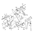
ベースブラケット11には、ドアロック機構ベース(ドアロック機構)12が固定されている。このドアロック機構ベース12は、図5に示すように、ストライカ13の進入溝14を有し、この進入溝14の両側に、フック15とラチェット16が軸15aと16aでそれぞれ枢着されている。このフック15とラチェット16は、図示しないばね手段により、それぞれ矢印A、B方向に回動付勢されている。ドアロック機構ベース12(ベースブラケット11)とストライカ13の一方は、車両のドアに、他方は車両ボディにそれぞれ固定される。
【0007】
図5は、フック15の保持溝15b内にストライカ13が保持され、フック15の図における時計方向への回動をラチェット16が阻止しているロック状態を示している。図5の状態において、B方向の付勢力に抗しラチェット16を蹴って時計方向に回動させ、フック15との係合を解くと、フック15がA方向の付勢力により時計方向に回動し、ストライカ13を開放する(ドアを開く)。一方、ドアを閉めると、ストライカ13が進入溝14から保持溝15b内に進入して、A方向の付勢力に抗してフック15を図の反時計方向に回動させ、ラチェット16が図5の位置にフック15を保持してロックする。
【0008】
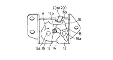
ベースブラケット11には、ラチェット16の蹴とばし突起16bを蹴って、ドアロック機構ベース12のロックを解除するオープンレバー20が軸21で枢着されている。オープンレバー20には、軸21と同軸に、ドアハンドル連動レバー22が相対回動自在に枢着されており、このドアハンドル連動レバー22は、操作ワイヤ23を介して図示しないドアハンドルに接続されている。23aは、操作ワイヤ23の端部に設けた連動レバー22との接続突起である。オープンレバー20には、切換連動ブロックの摺動溝20aが形成されており、この摺動溝20aに、切換連動ブロック24が摺動自在に支持されている。切換連動ブロック24は、図の斜め下方の伝達位置24A(図2)と斜め上方の非伝達位置24B(図3、図4)との間を摺動可能である。
【0009】
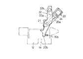
ドアハンドル連動レバー22は、伝達位置24Aにある切換連動ブロック24の側面と係合する連動壁22aと、非伝達位置24Bにある切換連動ブロック24を逃がす(と係合しない)逃げ段部22b(図1)とが形成されている。切換連動ブロック24が伝達位置24Aにあるとき、ドアハンドル連動レバー22が操作ワイヤ23によりロック解除方向に引かれると、連動壁22aが切換連動ブロック24を介してオープンレバー20をロック解除方向に揺動させ、オープンレバー20の先端の蹴とばし部20bがラチェット16の蹴とばし突起16bを蹴って、ドアロック機構ベース12のドアロックを解除する。
【0010】
一方、切換連動ブロック24が非伝達位置24Bにあるとき、ドアハンドル連動レバー22が操作ワイヤ23によりロック解除方向に引かれると、逃げ段部22bは切換連動ブロック24と当接しないので、該連動レバー22が空振りする(図7)。つまり、ドアハンドルを引いても、ドアロックは解除されない。オープンレバー20とドアハンドル連動レバー22は、トーションコイルばね25により、常時図の時計方向、つまり蹴とばし部20bが蹴とばし突起16bから離間する方向に回動付勢されている。
【0011】
ベースブラケット11には、軸30により、ロッキングレバー31が枢着されている。このロッキングレバー31は、その両端部に、円弧状長孔31aと案内溝31bを有し、円弧状長孔31aには、上記切換連動ブロック24が係合している。この円弧状長孔31aは、ロッキングレバー31が図3、図4に示すロック位置に回動しているときには、切換連動ブロック24を摺動溝20aに沿って非伝達位置24Bに位置させ、ロッキングレバー31が図2に示すアンロック位置に回動しているときには、切換連動ブロック24を伝達位置24Aに位置させる。
【0012】
一方、ロッキングレバー31の案内溝31bには、キーシリンダ40とロッキングレバー31とを接続するコネクタロッド42の一端部が係合している。すなわち、コネクタロッド42のロッキングレバー31側の端部には、案内溝31b内を摺動するローラ32が設けられている。またこのコネクタロッド42の他端部は、キーシリンダ40のロータ43に一体に設けた径方向アーム43aに軸44で枢着されている。キーシリンダ40は、周知のように、キー挿入溝にキーを挿入し、該キーを回動させることにより、ロータ43の回動操作ができる。なお、ローラ32は、必ずしも必要ではなく、単なるピンに代えてもよい。
【0013】
コネクタロッド42の一端部のローラ32は、ベースブラケット11に形成した案内溝11aにも同時に嵌まっている。この案内溝11aは、ローラ32がこの案内溝11a内を移動するときロッキングレバー31を回動させる回動区間pと、ローラ32が案内溝11a内を移動しても、ロッキングレバー31を回動させない非回動区間qとを有し、ロッキングレバー31の案内溝31bは、ロッキングレバー31がロック位置(図3)に回動した状態では、非回動区間qの案内溝11aと重なる。ロッキングレバー31は、トーションばね34により、ロック方向に回動付勢されている。またロッキングレバー31には、コネクタロッド42とは別に、軸35で、別系統のコネクタロッド36の一端部が枢着されている。このコネクタロッド36の他端部は、例えば、車両室内側のロックレバーに接続されていて、ロックレバーをロック位置とアンロック位置に移動させると、ロッキングレバー31が図3のドアロック位置と図2のドアアンロック位置とに移動する。
【0014】
上記構成の本キーシリンダロック装置は、次のように作動する。いま、キーシリンダ40がアンロック位置にあると、ロータ43は、図2に示す回動位置にあり、コネクタロッド42のロッキングレバー31側の端部のローラ32は、案内溝11aの上端部(回動区間pの上端部)にある。この状態では、ロッキングレバー31はアンロック位置にあり、切換連動ブロック24は伝達位置24Aにある。この状態において、ドアハンドルを介して操作ワイヤ23を引くと、ドアハンドル連動レバー22が引かれ、連動壁22aが切換連動ブロック24を押してオープンレバー20をアンロック方向に回動させる。すると、オープンレバー20の蹴とばし部20bがラチェット16の蹴とばし突起16bを蹴って、ドアロックを解除する(ドアが開く)。
【0015】
一方、図2のアンロック状態において、キーシリンダ40のロータ43をロック位置に回動させると、径方向アーム43aに一端部が接続されているコネクタロッド42の他端部のローラ32は、案内溝11aの回動区間pを下降し、このとき同時に、案内溝31b内を移動しながら、ロッキングレバー31を図2のアンロック位置から軸30を中心に反時計方向に回動させる。すると、切換連動ブロック24が図2の伝達位置24Aから図3の非伝達位置24Bに移動する。これがドアロック状態である。このロック状態において、ドアハンドルを介して操作ワイヤ23を引くと、ドアハンドル連動レバー22が引かれるが、切換連動ブロック24は非伝達位置24Bにあるので、オープンレバー20の逃げ段部22bが切換連動ブロック24に対して空振りする(図7)。つまり、ドアハンドルを引いても、ドアロックは解除されない(ドアは開かない)。
【0016】
以上のドアのロックとアンロックは、コネクタロッド36を介してロッキングレバー31を回動させても、全く同様に生じる。
【0017】
次に、キーシリンダ40のロータ43をロック位置を過ぎたオーバ回動位置に回動させると、ロータ43の径方向アーム43aは、図4に示す位置にオーバ回動位置に回動する。このロック位置からオーバ回動位置へのロータ43の回動の際には、コネクタロッド42の先端のローラ32は、案内溝11aの非回動区間qを移動し、同時に、ロッキングレバー31の案内溝31b内を移動する。案内溝11aの非回動区間qと、これに重なる案内溝31bの形状は、ローラ32のこの移動では、ロッキングレバー31を回動させないように設定されており、従って、ロック状態を維持したまま、別の仕事、例えばガラスハッチのロック解除、ウィンドレギュレータの操作等を行なわせることができる。この別の仕事は、最も簡単には、キーシリンダ40のロータ43をロック位置からオーバ回動位置へ回動させたとき、スイッチ45(図4)を押圧作動させることで行なわせることができる。あるいは、ロータ43に別の径方向アーム43bを一体に突出させ、この径方向アーム43bを、コネクタロッド46を介して、他の機構、例えば、ガラスハッチのロック機構と接続することにより、機械的に、このウィンドロック機構を操作することができる。
【0018】
図8、図9は、本発明の別の実施形態を示している。この実施形態は、キーシリンダ40に、ロック位置を越えた第1のオーバ回動位置に加えて、アンロック位置を越えた第2のオーバ回動位置を設け、この第2のオーバ回動位置においても、別の仕事ができるようにした実施形態である。第1の実施形態と異なる点は、ベースブラケット11の案内溝11aに、回動区間pに連続させて、非回動区間qとは反対側に位置する第2の非回動区間rを設けた点、及びロッキングレバー31に、該ロッキングレバー31がアンロック位置に回動したとき、この案内溝11aの非回動区間rに一致する(重なる)、案内溝31bに連続する案内溝31b’を設けた点である。
【0019】
この実施形態では、キーシリンダ40のロータ43を、アンロック位置を越えて第2のオーバ回動位置に回動させると、径方向アーム43aは、図8に示す位置に回動する。このアンロック位置から第2のオーバ回動位置へのロータ43の回動の際には、コネクタロッド42の先端のローラ32は、案内溝11aの非回動区間rを移動し、同時に、ロッキングレバー31の案内溝31b’内を移動する。案内溝11aの非回動区間rと、これに重なる案内溝31b’の形状は、ローラ32のこの移動では、ロッキングレバー31を回動させないように設定されており、従って、アンロック状態を維持したまま、別の仕事、例えばガラスハッチのロック解除、ウィンドレギュレータの操作等を行なわせることができる。この別の仕事は、最も簡単には、キーシリンダ40のロータ43をロック位置から第2のオーバ回動位置へ回動させたとき、スイッチ47(図8)を押圧作動させることで行なわせることができる。勿論、図4のように、ロータ43に別のコネクタロッドを結合しておき、機械的に仕事を行なわせることもできる。
【0020】
なお、キーシリンダ40は、キーを用いてロータ43をオーバ回動位置へ回動させた後操作力を開放すると、ロータ43をロック位置またはアンロック位置に自動復帰させるばね手段を内蔵することが好ましい。
【0021】
【発明の効果】
本発明によれば、オーバ回動位置でドアロック、ドアロック解除以外の別の仕事を行なわせるキーシリンダロック装置を、少ない構成部品の簡単な構造で安価に得ることができる。
【図面の簡単な説明】
【図1】本発明による車両のキーシリンダロック装置の一実施形態を示す分解斜視図である。
【図2】図1のロック装置のアンロック状態の正面図である。
【図3】図1のロック装置のロック状態の正面図である。
【図4】図1のロック装置のキーシリンダのオーバ回動状態の正面図である。
【図5】ドアロック機構の平面図である。
【図6】ドアロック機構のラチェットとオープンレバーの関係を示す正面図である。
【図7】ドアハンドル連動レバーがオープンレバーに対して空振りした状態を示す正面図である。
【図8】本発明による車両のキーシリンダロック装置の別の実施形態を示す正面図である。
【図9】図8のロック装置のベースブラケットとロッキングレバーの案内溝の形状を示す斜視図である。
【符号の説明】
11 ベースブラケット
11a 案内溝
p r 回動区間
q 非回動区間
12 ドアロック機構ベース
13 ストライカ
15 フック
16 ラチェット
20 オープンレバー
20a 摺動溝
20b 蹴とばし部
22 ドアハンドル連動レバー
22a 連動壁
22b 逃げ段部
23 操作ワイヤ
24 切換連動ブロック(切替連動部材)
24A 伝達位置
24B 非伝達位置
31 ロッキングレバー
31a 円弧状長孔
31b 31b’ 案内溝
32 ローラ
36 コネクタロッド(別系統アクチュエータ)
40 キーシリンダ
42 コネクタロッド
43 ロータ
43a 43b 径方向アーム[0001]
【Technical field】
The present invention relates to a lock device for a vehicle operated by a key cylinder, and in particular, the key cylinder has an over rotation position in addition to a lock position and an unlock position, and performs another work at the over rotation position. The present invention relates to a type of key cylinder lock device.
[0002]
[Prior art and its problems]
This type of key cylinder locking device is already known. Other tasks currently include unlocking glass hatches and operating window regulators. However, the conventional structure has a large number of parts, a complicated structure, and a high cost.
[0003]
OBJECT OF THE INVENTION
It is an object of the present invention to obtain this type of key cylinder lock device with fewer parts, a simple structure and a low cost.
[0004]
SUMMARY OF THE INVENTION
A key cylinder lock device for a vehicle according to the present invention includes a door lock mechanism for gripping or releasing a striker; at least one of a lock position and an unlock position of the door lock mechanism and at least one of the lock position and the unlock position. A key cylinder that can be rotated to the over-rotation position and performs another work at this over-rotation position; a locking lever pivotally attached to the base bracket; and a rotation operation between the lock position and the unlock position of the key cylinder A connector rod that pivots the locking lever to the locked and unlocked positions; pivoted on the base bracket and pulled by the door handle unlocking operation; pivoted coaxially with the door handle interlocking lever; The lock mechanism is unlocked when swung in the unlocking direction. An open lever; a switching interlock member that is supported by the open lever so that the movement of the door handle interlocking lever can be moved between a transmission position that transmits the movement to the open lever and a non-transmission position that does not transmit to the open lever; a locking lever and a switching interlocking member Means that the switching interlock member is coupled to move to the transmission position and the non-transmission position when the locking lever rotates between the lock position and the unlock position; and the locking lever and the base bracket Each has a guide groove that allows the key cylinder to rotate to the over-rotation position while the locking lever is held in the unlocked position when the locking lever is in the unlocked position; It is characterized by.
[0005]
The key cylinder can be provided with two over-turned position beyond both the locked position and the unlocked position.
[0006]
DETAILED DESCRIPTION OF THE INVENTION
A door lock mechanism base (door lock mechanism) 12 is fixed to the
[0007]
FIG. 5 shows a locked state in which the
[0008]
An
[0009]
The door handle interlocking lever 22 escapes (does not engage) the interlocking
[0010]
On the other hand, when the
[0011]
A
[0012]
On the other hand, one end of a
[0013]
The
[0014]
The key cylinder lock device having the above-described configuration operates as follows. Now, when the
[0015]
On the other hand, when the
[0016]
The locking and unlocking of the door described above occurs in exactly the same manner even when the locking
[0017]
Next, when the
[0018]
8 and 9 show another embodiment of the present invention. In this embodiment, the
[0019]
In this embodiment, when the
[0020]
The
[0021]
【The invention's effect】
According to the present invention, it is possible to obtain a key cylinder lock device that performs another work other than the door lock and the door lock release at the over rotation position at a low cost with a simple structure with a small number of components.
[Brief description of the drawings]
FIG. 1 is an exploded perspective view showing an embodiment of a key cylinder lock device for a vehicle according to the present invention.
FIG. 2 is a front view of the unlocking state of the locking device of FIG. 1;
FIG. 3 is a front view of the locking device of FIG. 1 in a locked state.
4 is a front view of the key cylinder of the locking device of FIG. 1 in an over-rotating state.
FIG. 5 is a plan view of a door lock mechanism.
FIG. 6 is a front view showing a relationship between a ratchet of the door lock mechanism and an open lever.
FIG. 7 is a front view showing a state in which the door handle interlocking lever is swung with respect to the open lever.
FIG. 8 is a front view showing another embodiment of the key cylinder lock device for a vehicle according to the present invention.
9 is a perspective view showing the shapes of the guide brackets of the base bracket and the locking lever of the locking device of FIG.
[Explanation of symbols]
11
24A Transmission position
40
Claims (2)
このドアロック機構のロック位置とアンロック位置、及びこのロック位置とアンロック位置の少なくとも一方を越えた少なくとも一つのオーバ回動位置に回動操作可能で、このオーバ回動位置で別の仕事をさせるキーシリンダ;
ベースブラケットに枢着したロッキングレバー;
上記キーシリンダのロック位置とアンロック位置の間の回動動作によりこのロッキングレバーをロック位置とアンロック位置に回動させるコネクタロッド;
上記ベースブラケットに枢着され、ドアハンドルのロック解除動作によって引かれるドアハンドル連動レバー;
このドアハンドル連動レバーと同軸に枢着され、ロック解除方向に揺動されたとき上記ロック機構のロックを解除するオープンレバー;
このオープンレバーに、上記ドアハンドル連動レバーの動きを該オープンレバーに伝達する伝達位置と、伝達しない非伝達位置との間を移動可能にして支持した切替連動部材;
上記ロッキングレバーと切替連動部材とは、該ロッキングレバーがロック位置とアンロック位置の間を回動移動するとき、切替連動部材が上記伝達位置と非伝達位置に移動するように結合されていること;及び
ロッキングレバーとベースブラケットにはそれぞれ、ロッキングレバーがアンロック位置にあるとき、該ロッキングレバーをアンロック位置に保持したまま、キーシリンダのオーバ回動位置への回動を可能とする案内溝が形成されていること;
を備えたことを特徴とする車両のキーシリンダロック装置。Door lock mechanism to grip or release the striker;
The door lock mechanism can be rotated to a lock position and an unlock position, and at least one over rotation position that exceeds at least one of the lock position and the unlock position. Key cylinder to make;
A locking lever pivotally attached to the base bracket;
A connector rod for rotating the locking lever to a locked position and an unlocked position by rotating between the lock position and the unlock position of the key cylinder;
A door handle interlocking lever pivotally attached to the base bracket and pulled by the door handle unlocking operation;
An open lever pivotally mounted coaxially with the door handle interlocking lever and unlocking the locking mechanism when swung in the unlocking direction;
A switching interlocking member supported by the open lever so as to be movable between a transmission position where the movement of the door handle interlocking lever is transmitted to the open lever and a non-transmission position where it is not transmitted;
The locking lever and the switching interlock member are coupled so that the switching interlock member moves to the transmission position and the non-transmission position when the locking lever rotates between the lock position and the unlock position. Each of the locking lever and the base bracket has a guide groove that allows the key cylinder to rotate to the over-rotation position while the locking lever is held in the unlock position when the locking lever is in the unlock position. Is formed;
A key cylinder lock device for a vehicle, comprising:
Priority Applications (1)
| Application Number | Priority Date | Filing Date | Title |
|---|---|---|---|
| JP34543096A JP3670100B2 (en) | 1996-12-25 | 1996-12-25 | Vehicle key cylinder lock device |
Applications Claiming Priority (1)
| Application Number | Priority Date | Filing Date | Title |
|---|---|---|---|
| JP34543096A JP3670100B2 (en) | 1996-12-25 | 1996-12-25 | Vehicle key cylinder lock device |
Publications (2)
| Publication Number | Publication Date |
|---|---|
| JPH10184143A JPH10184143A (en) | 1998-07-14 |
| JP3670100B2 true JP3670100B2 (en) | 2005-07-13 |
Family
ID=18376545
Family Applications (1)
| Application Number | Title | Priority Date | Filing Date |
|---|---|---|---|
| JP34543096A Expired - Fee Related JP3670100B2 (en) | 1996-12-25 | 1996-12-25 | Vehicle key cylinder lock device |
Country Status (1)
| Country | Link |
|---|---|
| JP (1) | JP3670100B2 (en) |
Families Citing this family (1)
| Publication number | Priority date | Publication date | Assignee | Title |
|---|---|---|---|---|
| US7303773B2 (en) | 2003-10-21 | 2007-12-04 | The Procter & Gamble Company | Process for enriching extracts of natural theanine |
-
1996
- 1996-12-25 JP JP34543096A patent/JP3670100B2/en not_active Expired - Fee Related
Also Published As
| Publication number | Publication date |
|---|---|
| JPH10184143A (en) | 1998-07-14 |
Similar Documents
| Publication | Publication Date | Title |
|---|---|---|
| US6135513A (en) | Operational apparatus for vehicle slide door | |
| US4986579A (en) | Door closing device | |
| GB2339449A (en) | Door lock system | |
| JPH0353135B2 (en) | ||
| JP2005240454A (en) | Vehicle door latch device for rear door | |
| JP2007085032A (en) | Vehicle door handle device | |
| JP3670100B2 (en) | Vehicle key cylinder lock device | |
| JPH08312220A (en) | Slide door and unlocking mechanism and locking device thereof | |
| JPH0452349B2 (en) | ||
| JP2005213818A (en) | Door operating device for vehicle | |
| JP4374674B2 (en) | Vehicle door lock device | |
| JP2748268B2 (en) | Door lock device | |
| JP4070993B2 (en) | Vehicle locking device with cancel mechanism | |
| KR100748712B1 (en) | Door opening and closing device for building | |
| JP3588996B2 (en) | Automotive door lock device | |
| JP3471420B2 (en) | Door lock device | |
| JP2868251B2 (en) | Door lock device for automobile | |
| JP2662736B2 (en) | Door lock device | |
| JP4277345B2 (en) | Vehicle door lock actuator | |
| JP3842479B2 (en) | Handle mechanism of door lock device | |
| JP3844410B2 (en) | Door lock device | |
| JP3134579B2 (en) | Car door lock knob structure | |
| JP2663284B2 (en) | Door lock device | |
| JP3542045B2 (en) | Sliding door lock operation mechanism | |
| JPS5831960Y2 (en) | door lock device |
Legal Events
| Date | Code | Title | Description |
|---|---|---|---|
| A977 | Report on retrieval |
Free format text: JAPANESE INTERMEDIATE CODE: A971007 Effective date: 20041214 |
|
| A131 | Notification of reasons for refusal |
Free format text: JAPANESE INTERMEDIATE CODE: A131 Effective date: 20050105 |
|
| A521 | Written amendment |
Free format text: JAPANESE INTERMEDIATE CODE: A523 Effective date: 20050303 |
|
| TRDD | Decision of grant or rejection written | ||
| A01 | Written decision to grant a patent or to grant a registration (utility model) |
Free format text: JAPANESE INTERMEDIATE CODE: A01 Effective date: 20050412 |
|
| A61 | First payment of annual fees (during grant procedure) |
Free format text: JAPANESE INTERMEDIATE CODE: A61 Effective date: 20050413 |
|
| R150 | Certificate of patent (=grant) or registration of utility model |
Free format text: JAPANESE INTERMEDIATE CODE: R150 |
|
| FPAY | Renewal fee payment (prs date is renewal date of database) |
Free format text: PAYMENT UNTIL: 20080422 Year of fee payment: 3 |
|
| FPAY | Renewal fee payment (prs date is renewal date of database) |
Free format text: PAYMENT UNTIL: 20090422 Year of fee payment: 4 |
|
| FPAY | Renewal fee payment (prs date is renewal date of database) |
Free format text: PAYMENT UNTIL: 20090422 Year of fee payment: 4 |
|
| FPAY | Renewal fee payment (prs date is renewal date of database) |
Free format text: PAYMENT UNTIL: 20100422 Year of fee payment: 5 |
|
| FPAY | Renewal fee payment (prs date is renewal date of database) |
Free format text: PAYMENT UNTIL: 20110422 Year of fee payment: 6 |
|
| LAPS | Cancellation because of no payment of annual fees |