JP3666962B2 - Hydraulic shock absorber - Google Patents
Hydraulic shock absorber Download PDFInfo
- Publication number
- JP3666962B2 JP3666962B2 JP34835695A JP34835695A JP3666962B2 JP 3666962 B2 JP3666962 B2 JP 3666962B2 JP 34835695 A JP34835695 A JP 34835695A JP 34835695 A JP34835695 A JP 34835695A JP 3666962 B2 JP3666962 B2 JP 3666962B2
- Authority
- JP
- Japan
- Prior art keywords
- piston
- spool
- oil chamber
- side oil
- shock absorber
- Prior art date
- Legal status (The legal status is an assumption and is not a legal conclusion. Google has not performed a legal analysis and makes no representation as to the accuracy of the status listed.)
- Expired - Fee Related
Links
Images

Description
【0001】
【発明の属する技術分野】
この発明は、車両搭載用の油圧緩衝器に関し、特に、振動周波数に感応して発生減衰力が所謂ハイカット調整されるようにした油圧緩衝器の改良に関する。
【0002】
【従来の技術】
近年、車両に搭載される油圧緩衝器は、振動周波数に感応して発生減衰力が調整されるように構成されることが多い。
【0003】
例えば、本出願人は、振動周波数に適確に感応して所定の減衰力を発生し得て車両への搭載に最適となる油圧緩衝器を開発している(特願平7−246741号)。
【0004】
この油圧緩衝器は、図2に示すように、シリンダ1内にピストン3を介して二つの油室A,Bが区画され、二つの油室A,Bは、減衰バルブ4を介して開閉され、更に、前記減衰バルブ4を迂回して二つの油室A,Bを開閉するバイパス路Rが形成されている油圧緩衝器であり、バイパス路Rの途中に当該バイパス路Rを開閉するスプール10を摺動自在に配設し、スプール10の受圧面側に形成される受圧面側油室R3とスプール10の背圧面側に形成される背圧面側油室R4とをオリフィス17aを介して連通させ、更に、背圧面側油室R4内にはフリーピストン13が摺動自在に挿入され、このフリーピストン13と前記スプール10との間に当該スプール10を閉じ方向に付勢するスプリング12を介在させたとするものである。
【0005】
上記の場合、バイパス路Rは、ピストンロッド2と、このピストンロッド2の下端に連設したピストンナット6内に形成され、ピストンナット内中空部にスプール10とフリーピストン13とが直列に配置されている。上記の油圧緩衝器によれば、シリンダ1内における振動周波数が低周波数領域にある場合には、例えば、高圧側油室Aからの油圧がスプール10の受圧面側に形成されている受圧面側油室R3に供給されると共に、オリフィス17aを介してスプール10の背圧面側に形成されている背圧面側油室R4にも供給される。このとき、受圧面側油室R3と背圧面側油室R4との間には、油圧差が現出されず、静止状態に維持されてバイパス路Rが閉鎖状態に維持される。
【0006】
その結果、高圧側油室Aからの作動油が減衰バルブ4のみを通過して低圧側油室R4に流出し、減衰バルブ4で設定された所定の減衰力の発生が可能になる。
【0007】
一方、シリンダ1内における振動周波数が低周波数領域を脱して、特に、高周波数領域になると、高圧側油室Aからの油圧が受圧面側油室R3には供給されるが、オリフィス17aを介しての油圧が背圧面側油室R4には供給されなくなる。
【0008】
このとき、受圧面側油室R3と背圧面側油室R4との間には、油圧差が現出されることになり、スプール10が背圧面側油室R4に配在のスプリング12の付勢力に抗して後退方向に摺動してバイパス路Rを開放状態にする。
【0009】
この場合、スプール10の後退方向への摺動時には、背圧面側油室R4に配在されているフリーピストン13が後退しスプール10の摺動を保障する。
【0010】
その結果、高圧側油室Aからの作動油がバイパス路Rを通過して低圧側油室Bに流出することになり、減衰バルブ4を通過する油量が減り、減衰力が小さくなる。
【0011】
シリンダ1内における振動周波数が低周波数領域から高周波数領域になると、それまで発生されていた減衰力の発生状態がより低い減衰力の発生状態に変更調整され、減衰力が所謂ハイカット調整される。
【0012】
【発明が解決しようとする課題】
上記の油圧緩衝器によれば、上記のようなすぐれた効果があり、機能上は全く問題は無いが、スプール10とフリーピストン13とがピストンナット6内に軸方向に沿って直列に配置されているために、スプール10とフリーピストン13とを収容する軸方向のスペースを大きくする必要があり、この為に、ピストンナット6を長く成形する必要がある。従って、ピストンナット6が長くなった分十分なストロークをとるためにはシリンダ1の長さも長くなり、油圧緩衝器の全長も長くなり、油圧緩衝器の設置スペースが制約を受けるおそれが生じるという問題がある。そこで、本発明の目的は、周波数感応部たるスプールとフリーピストンとの収容スペースを小さくし、全長の短縮化が図れる油圧緩衝器を提供することである。
【0013】
【課題を解決するための手段】
上記の目的を達成するため、本発明の構成は、シリンダ内に二つの油室が区画され、二つの油室は減衰バルブを介して開閉され、更に、前記減衰バルブを迂回して二つの油室を連通するバイパス路が形成され、このバイパス路内には当該バイパス路を開閉するスプールと当該スプールと連動するフリーピストンとが移動自在に挿入され、バイパス路内におけるスプールの上面側油室と背面側油室とはスプールに設けたオリフィスを介して接続されている油圧緩衝器において、上記フリーピストンが筒状に形成され、このフリーピストン内にスプールが移動自在に挿入されていることをを特徴とするものである。
【0014】
この場合、減衰バルブがピストンに設けられ、バイパス路がピストンロッドと当該ピストンロッドの下端に設けた中空なピストンナット内に形成され、ピストンナット内の中空部にシールを介して下方に付勢された筒状のフリーピストンが上下移動自在に挿入され、更に、フリーピストンの内側にシールを介して上方に付勢された有底筒状のスプールが上下移動自在に挿入され、スプールの背面側油室の内圧がフリーピストンとの下端に作用しているようにするのが好ましい。
【0015】
【発明の実施の形態】
以下、本発明の実施の形態を図にもとづいて説明する。
【0016】
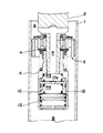
図1は、本発明の一実施の形態を示すもので、これは、シリンダ1内にピストン3を介してピストンロッド2が移動自在に挿入され、ピストン3は、シリンダ1内にロッド側油室Aとピストン側油室Bとを区画し、二つの油室A,Bは、ピストン3に設けた伸側ポート3bと圧側ポート3cを介して連通し、伸側ポート3aの出口側には伸側減衰バルブ4が開閉自在に設けられ、同じく圧側ポート3cの出口側にはチェック弁7が開閉自在に設けられたものである。更に、この実施の形態に係る油圧緩衝器は、上記伸側減衰バルブ4を迂回するバイパス路R3が形成され、このバイパス路R3は、ピストンロッド2とこのピストンロッド2の下部に結合したハウジングたるピストンナット6に形成され、当該バイパス路R3内にこのバイパス路R3を開閉するスプール10が移動自在に挿入されている。又、バイパス路R3内におけるスプール10の上面側油室6aと、一次遅れ圧力室たる背圧面側油室R4とはスプール10の中央に形成したオリフィス10aを介して接続され、スプール10の外周側にはフリーピストン13が移動自在に配設されている。
【0017】
バイパス路R3は、ピストン3に形成した通路3bと、ピストンロッド2に形成した横通路2a及び縦通路2bと、ピストンナット6内の中空部Cと、ピストンナット6に形成した横通路6cとで構成し、通路3bはロッド側油室Aに開口し、横通路6cはピストン側油室Bに開口している。
【0018】
ピストンナット6内の中空部Cは、下端にカシメ,ねじ,ピン等で固定された金属又はゴム等のキャップ14で密封されている。
【0019】
中空部C内には筒状のフリーピストン13が外周のシールを介して上下移動自在に挿入され、このフリーピストン13の内側には有底筒状のスプール10が外周のシールを介して上下移動自在に挿入されている。フリーピストン13の上端と中空部Cの上壁との間にはスプリング13aが介装されて常時フリーピストン13を下方に付勢している。フリーピストン13の下端は、通常キャップ14の上面に当接じているが、キャップ14の上面にクッション材を介在させてフリーピストン13が急激に下降したとき衝撃音の発生を防止させてもよい。但し、キャップ14が弾性材で成形させていれば上記のようなクッション材を入れる必要はない。
【0020】
フリーピストン13の下端には環状テーパ面が形成され、背面側油室R4の油圧が作用するようになっている。
【0021】
スプール10は、背面側油室R4内に設けたスプリング12で上方に、即ち、閉じ方向に付勢されており、該スプール10の中央にはオリフィス10aが形成されている。
【0022】
スプール10の上端には環状の突起10bが形成され、スプール10の上側に上面側油室6bを区画している。但し、この突起10bは、無くても使用可能である。
【0023】
以上のように形成されたこの実施の態様に係る油圧緩衝器では、ピストン3がシリンダ1内を上昇する伸側行程時には、基本的には、高圧側油室となるロッド側油室Aからの作動油がピストン3の伸側バルブ4を介して低圧側油室たるピストン側油室Bに流出される。そして、作動油が伸側バルブ4を通過するときに、所定の大きさの伸側減衰力が発生されることになる。
【0024】
ところで、上記の伸側行程時には、ロッド側油室Aからの油圧がピストン3に設けた通路3aとピストンロッド2に開穿の通路2a,2bを介してスプール10の受圧面側に形成されている上面側油室6a内に作用する。
【0025】
このとき、ピストン3の振動周波数が低周波数領域にあるときには、上面側油室6aに供給された油圧がオリフィス10aを介してスプール10の背圧面側に形成されている背圧面側油室R4にも供給される。このため上面側油室6aと背圧面側油室R4との間は同圧となって油圧差が現出されなくなり、それ故、スプール10がスプリング12で中立状態に維持されていることと相俟って静止状態に維持され、バイパス路R3が閉鎖状態に維持されることになる。
【0026】
その結果、上記の伸側行程時には、ロッド側油室Aからの作動油が減衰バルブ4のみを通過して低圧側油室たるピストン側油室Bに流出することになり、減衰バルブ4で設定された所定の高い減衰力の発生が可能になる。
【0027】
上記伸側行程時において、ピストン3の振動周波数が低周波数領域を脱して、特に、高周波数領域になると、ロッド側油室Aからの油圧が上面側油室6aには供給されるが、オリフィス10aの絞りにより背圧面側油室R4には供給されなくなる。
【0028】
その結果、このときには、上面側油室6aと背圧面側油室R4との間では上面側油室6aの内圧の方が高くなり、その結果、油圧差が現出されることになり、スプール10が背圧面側油室R4に配在のスプリング12の付勢力に抗して図中で下降方向となる後退方向に摺動してバイパス路R3を開放状態にする。
【0029】
尚、スプール10の後退方向への摺動時には、フリーピストン13がこれを付勢するスプリング13aの付勢力に抗して図中で上昇するように後退してスプール10の摺動を保障する。
【0030】
その結果、ロッド側油室Aからの作動油がバイパス路R3を通過してピストン側油室Bに流出することになり、伸側減衰バルブ4を通過する油量が減り、該伸側減衰バルブ4で設定された所定の低い減衰力が発生される。
【0031】
即ち、シリンダ1内における振動周波数が低周波数領域から高周波数領域になると、それまで発生されていた減衰力の発生状態がより低い減衰力の発生状態に変更調整される。即ち、減衰力が所謂ハイカット調整されることになる。
【0032】
上記した所謂ハイカット調整は、同じ構造のものを使用することにより、油圧緩衝器におけるベースバルブ部にも利用できることはいうまでもない。
【0033】
【発明の効果】
本発明によれば、次の効果がある。
【0034】
▲1▼各請求項の発明によれば、ピストン内の振動周波数が低周波数領域にあるときに、スプールが閉じ状態に維持されてバイパス路を閉鎖して言わば高い減衰力の発生を可能にする一方で、ピストン内の振動周波数が低周波数領域を脱し、特に、高周波数領域になるときには、スプールが摺動してバイパス路を開放して言わば低い減衰力の発生を可能にし、両者の減衰力差を大きくできる。入力振動が低周波数と高周波数とを混在する重畳波振動の場合であっても、高周波要素に感応して発生減衰力を低くする調整、即ち、所謂ハイカット調整が確実に実現されることになる利点がある。
【0035】
▲2▼同じく、スプールは、振動周波数が低周波数領域にあるときには、スプリングの付勢力によって中立状態におかれて閉じ状態におかれるように構成されてなるから、ピストン速度が低速域にあり、減衰力が低く、内圧が小さい時であっても、確実にバイパス路を閉鎖して所定の高減衰力の発生状態を実現できることになる利点がある。
【0036】
▲3▼同じく、油圧緩衝器が静止状態から極微低速で伸縮を開始するような場合にあっても、スプールによるバイパス路の閉鎖が予め実現されているから、高圧側油室からの作動油がバイパス路を介して低圧側油室に流出されることがなく、確実に所定の高減衰力の発生を期待できる利点がある。従って、この発明に係る油圧緩衝器は、振動周波数に適確に感応して所定の減衰力を発生し得て、車両への搭載に最適となる。
【0037】
▲4▼フリーピストンが筒状に形成され、このフリーピストン内にスプールが移動自在に挿入されているから、スプールとフリーピストンの縦方向の収容スペースはスプールのストロークに必要なスペースであればよく、これによりスプールとフリーピストンを挿入するバイパス路が短かくできる。いいかえれば、例えば、バイパス路を形成するピストンロッドとピストンナットの軸方向の長さを短かくでき、これによりシリンダを短かくでき、油圧緩衝器の全長の短縮化が図れる。
【図面の簡単な説明】
【図1】この発明の一実施の形態に係る油圧緩衝器を示す一部縦断面図である。
【図2】従来の油圧緩衝器を示す一部縦断面図である。
【符号の説明】
1 シリンダ
2 ピストンロッド
3 ピストン
4 減衰バルブとしての伸側減衰バルブ
6 ピストンナット
6a 上面側油室
10 スプール
10a オリフィス
12 スプリング
13 フリーピストン
A ロッド側油室
B ピストン側油室
R3 バイパス路
R4 背圧面側油室[0001]
BACKGROUND OF THE INVENTION
The present invention relates to a hydraulic shock absorber mounted on a vehicle, and more particularly to an improvement of a hydraulic shock absorber in which a generated damping force is so-called high cut adjusted in response to a vibration frequency.
[0002]
[Prior art]
In recent years, a hydraulic shock absorber mounted on a vehicle is often configured so that a generated damping force is adjusted in response to a vibration frequency.
[0003]
For example, the present applicant has developed a hydraulic shock absorber that can generate a predetermined damping force in response to the vibration frequency accurately and is optimal for mounting on a vehicle (Japanese Patent Application No. 7-246741). .
[0004]
As shown in FIG. 2, this hydraulic shock absorber has two oil chambers A and B defined in a cylinder 1 via a
[0005]
In the above case, the bypass path R is formed in the piston rod 2 and the
[0006]
As a result, the hydraulic oil from the high-pressure side oil chamber A passes only through the
[0007]
On the other hand, when the vibration frequency in the cylinder 1 moves out of the low frequency region, and particularly into the high frequency region, the oil pressure from the high pressure side oil chamber A is supplied to the pressure receiving surface side oil chamber R3, but through the orifice 17a. All hydraulic pressure is not supplied to the back pressure surface side oil chamber R4.
[0008]
At this time, a hydraulic pressure difference appears between the pressure receiving surface side oil chamber R3 and the back pressure surface side oil chamber R4, and the
[0009]
In this case, when the
[0010]
As a result, the hydraulic oil from the high-pressure side oil chamber A passes through the bypass R and flows out to the low-pressure side oil chamber B, so that the amount of oil passing through the
[0011]
When the vibration frequency in the cylinder 1 changes from the low frequency region to the high frequency region, the state of generation of the damping force that has been generated so far is changed and adjusted to a state of generation of a lower damping force, and the damping force is so-called high cut adjustment.
[0012]
[Problems to be solved by the invention]
According to the hydraulic shock absorber described above, there are excellent effects as described above, and there is no problem in function. However, the
[0013]
[Means for Solving the Problems]
In order to achieve the above object, the configuration of the present invention is divided into two oil chambers in a cylinder, the two oil chambers are opened and closed via a damping valve, and further, two oil chambers are bypassed through the damping valve. A bypass path communicating with the chamber is formed, and a spool for opening and closing the bypass path and a free piston interlocking with the spool are movably inserted into the bypass path, and an upper surface side oil chamber of the spool in the bypass path In the hydraulic shock absorber connected to the back side oil chamber through an orifice provided in the spool, the free piston is formed in a cylindrical shape, and the spool is movably inserted into the free piston. It is a feature.
[0014]
In this case, a damping valve is provided in the piston, and a bypass path is formed in the piston rod and a hollow piston nut provided at the lower end of the piston rod, and is urged downward through a seal in the hollow portion in the piston nut. A cylindrical free piston is inserted so that it can move up and down, and a bottomed cylindrical spool that is urged upward via a seal inside the free piston is inserted so that it can move up and down. It is preferable that the internal pressure of the chamber acts on the lower end of the free piston.
[0015]
DETAILED DESCRIPTION OF THE INVENTION
Hereinafter, embodiments of the present invention will be described with reference to the drawings.
[0016]
FIG. 1 shows an embodiment of the present invention, in which a piston rod 2 is movably inserted into a cylinder 1 via a
[0017]
The bypass passage R3 includes a
[0018]
The hollow portion C in the
[0019]
A cylindrical
[0020]
An annular tapered surface is formed at the lower end of the
[0021]
The
[0022]
An annular protrusion 10 b is formed at the upper end of the
[0023]
In the hydraulic shock absorber according to this embodiment formed as described above, basically, from the rod side oil chamber A, which becomes the high pressure side oil chamber, during the extension stroke in which the
[0024]
By the way, at the time of the above extension side stroke, the oil pressure from the rod side oil chamber A is formed on the pressure receiving surface side of the
[0025]
At this time, when the vibration frequency of the
[0026]
As a result, during the above extension stroke, the hydraulic oil from the rod side oil chamber A passes only through the damping
[0027]
During the extension stroke, when the vibration frequency of the
[0028]
As a result, at this time, the internal pressure of the upper surface side oil chamber 6a is higher between the upper surface side oil chamber 6a and the back pressure surface side oil chamber R4, and as a result, a hydraulic pressure difference appears, and the
[0029]
When the
[0030]
As a result, the hydraulic oil from the rod side oil chamber A passes through the bypass passage R3 and flows out to the piston side oil chamber B, and the amount of oil passing through the extension
[0031]
That is, when the vibration frequency in the cylinder 1 changes from the low frequency region to the high frequency region, the damping force generation state that has been generated so far is changed and adjusted to a lower damping force generation state. That is, the damping force is so-called high cut adjustment.
[0032]
It goes without saying that the so-called high cut adjustment described above can be used for a base valve portion in a hydraulic shock absorber by using the same structure.
[0033]
【The invention's effect】
The present invention has the following effects.
[0034]
(1) According to the invention of each claim, when the vibration frequency in the piston is in the low frequency region, the spool is maintained in the closed state to close the bypass passage, so that a high damping force can be generated. On the other hand, when the vibration frequency in the piston goes out of the low frequency range, especially in the high frequency range, the spool slides to open the bypass passage, so that it is possible to generate a low damping force. The difference can be increased. Even when the input vibration is a superimposed wave vibration in which a low frequency and a high frequency are mixed, an adjustment that lowers the generated damping force in response to a high-frequency element, that is, a so-called high cut adjustment is surely realized. There are advantages.
[0035]
(2) Similarly, when the vibration frequency is in the low frequency range, the spool is configured to be placed in a neutral state and closed by the biasing force of the spring, so that the piston speed is in the low speed range, Even when the damping force is low and the internal pressure is small, there is an advantage that a predetermined high damping force can be generated by reliably closing the bypass.
[0036]
(3) Similarly, even when the hydraulic shock absorber starts expanding and contracting at a very low speed from a stationary state, the bypass passage is closed by the spool in advance, so that the hydraulic oil from the high-pressure side oil chamber is not There is an advantage that a predetermined high damping force can be reliably generated without being discharged into the low pressure side oil chamber via the bypass. Therefore, the hydraulic shock absorber according to the present invention can generate a predetermined damping force in response to the vibration frequency accurately, and is optimal for mounting on a vehicle.
[0037]
(4) Since the free piston is formed in a cylindrical shape, and the spool is movably inserted into the free piston, the accommodation space in the vertical direction of the spool and free piston only needs to be a space necessary for the stroke of the spool. This shortens the bypass path for inserting the spool and the free piston. In other words, for example, the axial lengths of the piston rod and the piston nut forming the bypass passage can be shortened, whereby the cylinder can be shortened and the overall length of the hydraulic shock absorber can be shortened.
[Brief description of the drawings]
FIG. 1 is a partial longitudinal sectional view showing a hydraulic shock absorber according to an embodiment of the present invention.
FIG. 2 is a partial longitudinal sectional view showing a conventional hydraulic shock absorber.
[Explanation of symbols]
DESCRIPTION OF SYMBOLS 1 Cylinder 2
Claims (2)
Priority Applications (1)
| Application Number | Priority Date | Filing Date | Title |
|---|---|---|---|
| JP34835695A JP3666962B2 (en) | 1995-12-18 | 1995-12-18 | Hydraulic shock absorber |
Applications Claiming Priority (1)
| Application Number | Priority Date | Filing Date | Title |
|---|---|---|---|
| JP34835695A JP3666962B2 (en) | 1995-12-18 | 1995-12-18 | Hydraulic shock absorber |
Publications (2)
| Publication Number | Publication Date |
|---|---|
| JPH09170641A JPH09170641A (en) | 1997-06-30 |
| JP3666962B2 true JP3666962B2 (en) | 2005-06-29 |
Family
ID=18396478
Family Applications (1)
| Application Number | Title | Priority Date | Filing Date |
|---|---|---|---|
| JP34835695A Expired - Fee Related JP3666962B2 (en) | 1995-12-18 | 1995-12-18 | Hydraulic shock absorber |
Country Status (1)
| Country | Link |
|---|---|
| JP (1) | JP3666962B2 (en) |
Families Citing this family (3)
| Publication number | Priority date | Publication date | Assignee | Title |
|---|---|---|---|---|
| JP5136789B2 (en) * | 2008-09-30 | 2013-02-06 | 日立オートモティブシステムズ株式会社 | Shock absorber |
| JP5483007B2 (en) * | 2010-01-29 | 2014-05-07 | 日立オートモティブシステムズ株式会社 | Shock absorber |
| JP6108532B2 (en) * | 2013-03-19 | 2017-04-05 | Kyb株式会社 | Shock absorber |
-
1995
- 1995-12-18 JP JP34835695A patent/JP3666962B2/en not_active Expired - Fee Related
Also Published As
| Publication number | Publication date |
|---|---|
| JPH09170641A (en) | 1997-06-30 |
Similar Documents
| Publication | Publication Date | Title |
|---|---|---|
| US6817454B2 (en) | Damping force control type hydraulic shock absorber | |
| JP3700958B2 (en) | Vehicle height adjustment device | |
| JP3626259B2 (en) | Hydraulic shock absorber | |
| JP2005344911A (en) | Hydraulic shock absorber | |
| JP3678830B2 (en) | Hydraulic shock absorber | |
| JP3666962B2 (en) | Hydraulic shock absorber | |
| JP3719454B2 (en) | Hydraulic shock absorber | |
| JP2006283924A (en) | Hydraulic damper for vehicle | |
| JP3666965B2 (en) | Hydraulic shock absorber | |
| JPH08226484A (en) | Hydraulic shockabsorber | |
| JP3777228B2 (en) | Pressure relief mechanism for relief valve | |
| JPH07190125A (en) | Hydraulic shock absorber | |
| JP2006283923A (en) | Hydraulic damper for vehicle | |
| JPH05248474A (en) | Shock absorber | |
| JPH11148527A (en) | Valve device of hydraulic shock absorber | |
| JPH10122290A (en) | Damping valve structure | |
| JPS598031Y2 (en) | Shock absorber | |
| JP2002161940A (en) | Front fork | |
| JP3131885B2 (en) | Hydraulic shock absorber | |
| JP2691590B2 (en) | Hydraulic shock absorber damping force generator | |
| JP4144944B2 (en) | Hydraulic shock absorber | |
| JP2003247584A (en) | Front fork | |
| JPH05231463A (en) | Shock absorber | |
| JP3938411B2 (en) | Hydraulic shock absorber | |
| JP2595198Y2 (en) | Position-dependent shock absorber |
Legal Events
| Date | Code | Title | Description |
|---|---|---|---|
| A977 | Report on retrieval |
Free format text: JAPANESE INTERMEDIATE CODE: A971007 Effective date: 20050215 |
|
| TRDD | Decision of grant or rejection written | ||
| A01 | Written decision to grant a patent or to grant a registration (utility model) |
Free format text: JAPANESE INTERMEDIATE CODE: A01 Effective date: 20050308 |
|
| A61 | First payment of annual fees (during grant procedure) |
Free format text: JAPANESE INTERMEDIATE CODE: A61 Effective date: 20050405 |
|
| FPAY | Renewal fee payment (event date is renewal date of database) |
Free format text: PAYMENT UNTIL: 20080415 Year of fee payment: 3 |
|
| FPAY | Renewal fee payment (event date is renewal date of database) |
Free format text: PAYMENT UNTIL: 20080415 Year of fee payment: 3 |
|
| FPAY | Renewal fee payment (event date is renewal date of database) |
Free format text: PAYMENT UNTIL: 20080415 Year of fee payment: 3 |
|
| FPAY | Renewal fee payment (event date is renewal date of database) |
Free format text: PAYMENT UNTIL: 20090415 Year of fee payment: 4 |
|
| FPAY | Renewal fee payment (event date is renewal date of database) |
Free format text: PAYMENT UNTIL: 20090415 Year of fee payment: 4 |
|
| FPAY | Renewal fee payment (event date is renewal date of database) |
Free format text: PAYMENT UNTIL: 20100415 Year of fee payment: 5 |
|
| LAPS | Cancellation because of no payment of annual fees |