JP3664416B2 - Building fence structure - Google Patents
Building fence structure Download PDFInfo
- Publication number
- JP3664416B2 JP3664416B2 JP17748496A JP17748496A JP3664416B2 JP 3664416 B2 JP3664416 B2 JP 3664416B2 JP 17748496 A JP17748496 A JP 17748496A JP 17748496 A JP17748496 A JP 17748496A JP 3664416 B2 JP3664416 B2 JP 3664416B2
- Authority
- JP
- Japan
- Prior art keywords
- enclosure
- cross member
- floor
- members
- slab
- Prior art date
- Legal status (The legal status is an assumption and is not a legal conclusion. Google has not performed a legal analysis and makes no representation as to the accuracy of the status listed.)
- Expired - Fee Related
Links
Images


Landscapes
- Steps, Ramps, And Handrails (AREA)
Description
【0001】
【発明の属する技術分野】
本発明は、共同住宅の外廊下やバルコニー床に設ける手摺などの建物の柵構造に関するものである。
【0002】
【従来の技術】
従来、この種の建物の柵構造を代表するものとして、ユニット化された手摺が知られている。この手摺は、外廊下を構成するスラブの端部に立設した複数本の支柱と、複数本の支柱の上端に掛け渡した笠木とで基本ユニットが構成され、この基本ユニットの各区画領域に格子ユニットやパネルユニットを装着する構造になっている。この場合、格子ユニットやパネルユニットは多種類のものが用意されており、基本ユニットを汎用的に用いてデザインの異なる各種の手摺を簡単に施工できるように構成されている。
【0003】
【発明が解決しようとする課題】
このような従来の手摺では、基本ユニットが手摺用に構成されているため、例えば、玄関ドアに面する部分に階高に渡って目隠しパネルを設ける場合などでは、別途、目隠しパネルと目隠しパネルを取り付ける構造材とを施工する必要があり、基本ユニットとの取り合いが煩雑になる問題があった。また、手摺と目隠しパネルとのデザイン上の統一が図り難くくなり、共同住宅の外廊下側の外観意匠が損なわれるおそれがあった。
【0004】
本発明は、共同住宅の外廊下側やバルコニー側に必要な手摺などの柵を簡単に施工することができると共に、外廊下側やバルコニー側全体の外観意匠の統一を図ることができる建物の柵構造を提供することをその目的としている。
【0005】
【課題を解決するための手段】
請求項1の建物の棚構造は、共同住宅の外廊下またはバルコニー床を構成する各階のスラブの外端部に、それぞれのリブ片を外側に向けて相互に平行に掛け渡した複数本の縦材、および当該縦材間に、それぞれのリブ片を外側に向けて相互に平行に掛け渡した複数本の横材から成る骨組みと、前記縦材と前記横材とで前記各リブ片先端が面一になるように区画した前記骨組みの各区画領域に装着可能な囲い体とを備え、前記骨組みは、前記複数本の縦材および複数本の横材により、各階のスラブの外端部において前記共同住宅の外廊下側の面の全域またはバルコニー床側の面の全域を格子状に覆っており、前記横材は、前記各階のスラブの近傍に配設した主横材と、当該主横材間の略中間位置に配設した副横材とを有し、前記囲い体は、前記副横材の上側に構成された前記区画領域を開放して下側に構成された前記区画領域に装着した囲い体と、前記上側及び下側に構成された区画領域に装着した囲い体とからなることを特徴とする。
【0006】
この構成によれば、共同住宅の外廊下側またはバルコニー側の全域に格子状の骨組みが設けられ、この骨組みの区画領域を1単位として、この区画領域の複数箇所を適宜埋めるように囲い体を装着することにより、外廊下などに必要な手摺や目隠しなどを簡単に構成することができる。また、外廊下側やバルコニー側の外観意匠を優先するように囲い体を装着することも可能になる。
【0008】
また、副横材の高さ位置を一般の笠木の位置とし、その下側の区画領域に囲い体を装着することにより、手摺付きの開放廊下などを構成することができる。この場合囲い体の選定により、通風を優先した外廊下やバルコニーとすることも、また風よけやプライバシーを優先した外廊下などとすることも可能である。
【0009】
共同住宅の外廊下またはバルコニー床を構成する各階のスラブの外端部に、それぞれのリブ片を外側に向けて相互に平行に掛け渡した複数本の縦材、および当該縦材間に、それぞれのリブ片を外側に向けて相互に平行に掛け渡した複数本の横材から成る骨組みと、前記縦材と前記横材とで前記各リブ片先端が面一になるように区画した前記骨組みの各区画領域に装着可能な囲い体とを備え、前記骨組みは、前記複数本の縦材および複数本の横材により、各階のスラブの外端部において前記共同住宅の外廊下側の面の全域またはバルコニー床側の面の全域を格子状に覆っており、前記横材は、前記各階のスラブの近傍に配設した主横材と、当該主横材間の略中間位置に配設した副横材とを有し、前記囲い体は、前記副横材の上側に構成された前記区画領域を開放して下側に構成された前記区画領域に装着した囲い体と、前記上側及び下側に構成された区画領域に装着した囲い体とからなる、建物の柵構造において、共同住宅の各戸には外廊下に面してドアが設けられており、ドアに対応する区画領域には、ドアを目隠しするように囲い体が装着されていることが、好ましい。
【0010】
この構成によれば、ドアに対応する区画領域に囲い体を装着することにより、玄関先などにおいて、目隠しや風よけを構成することができる。
【0011】
請求項1、2の建物の棚構造において、囲い体が、複数の格子と複数の格子を支持する枠体とを有する格子ユニットであることが好ましい。
【0012】
この構成によれば、骨組みの区画領域に格子ユニットを装着することで、簡単に手摺を構成することができる。また、損傷や改修に基づく格子ユニットの交換を簡単に行うことができる。
【0013】
請求項1、2または3の建物の柵構造において、囲い体が、化粧パネルと化粧パネルを支持する枠体とを有するパネルユニットであることが、好ましい。
【0014】
この構成によれば、骨組みの区画領域にパネルユニットを装着することで、簡単に目隠し機能を有する手摺や玄関先の目隠し(風よけ)を構成することができる。また、損傷や改修に基づくパネルユニットの交換を簡単に行うことができる。
【0015】
【発明の実施の形態】
以下、添付の図面を参照して、本発明の一実施形態に係る建物の柵構造について説明する。この柵構造は、例えばマンションなどの共同住宅の外廊下側の面に適用されるものである。図1の正面図に示すように、建物の外壁から延設した各階のスラブ2により各階の外廊下1が形成されている。スラブ2の外端の位置には、複数本の縦材4と複数本の横材5とから成る格子状に骨組み3が設けられており、縦材4と横材5とで区画された骨組み3の区画領域6には、手摺などを構成するように適宜、囲い体7が装着されている。
【0016】
具体的には、建物の外廊下1側の面の全域が格子状の骨組み3で覆われており、そのうちの手摺を設けようとする部分および風よけ(目隠し)を設けようとする部分には、区画領域6を単位として囲い体7が装着されている。
【0017】
縦材4は、階高に相当する寸法の複数本の単位縦材8を鉛直方向に連ねて構成されている。また、縦材4の配置ピッチは、建物の柱間の寸法を基準としてこれを均等分割し、1500mm〜1800mmになるように設定されている。もっとも、各戸の玄関ドア9に面する部分の縦材4は、この半分の配置ピッチで配設されている。一方、横材5は、縦材4の配置ピッチに相当する寸法の複数本の単位横材10を水平方向に連ねて構成されている。また、横材5は主横材5aと副横材5bとから成り、主横材5aは各階のスラブ2のわずかに上側となる位置に配設され、副横材5bは笠木に相当する位置に配設されている。なお、主横材5aと副横材5bは、形状等全く同一のものである。
【0018】
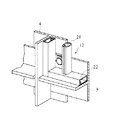
図2および図3に示すように、各階のスラブ2の外端部下面には「L」字状のブラケット11が固定されており、ブラケット11には当該階の単位縦材8の下端部と、階下の単位縦材8の上端部とがねじ止めされている。すなわち、「T」字状の形材などで構成された各単位縦材8は、そのリブ片8aを外側に向けた状態で、上下の両端部をそのフランジ片8bの部分でブラケット11にねじ止めされている。同様に、各単位横材10は「T」字状の形材などで構成されており、そのリブ片10aを外側に向けた状態で、左右の両端部をそのフランジ片10bの部分で縦材4にねじ止めされている。
【0019】
なお、ブラケット11と単位縦材8、および単位縦材8と単位横材10のそれぞれのねじ止め部分は、ねじ用の貫通孔が十字状に交わる長孔となっており、部材相互の位置合わせが容易に行えるようになっている。また、単位横材10のリブ片10aに対して単位縦材8のリブ片8aの突出長さが長く形成されており、単位縦材8に単位横材10を取り付けた状態では、それぞれのリブ片8a,10aの先端が面一になるように形成されている。
【0020】
一方、囲い体7は、手摺を構成するものとして格子ユニット12とパネルユニット13とが用意され、また玄関ドア9に面する目隠し(風よけ)を構成するものとして小型のパネルユニット14が用意されている。この場合、上記のパネルユニット13と小型のパネルユニット14とは、各区画領域6に対応させるために大きさは異なるが、同一構造のものを用いることが好ましい。
【0021】
図1は1住戸分の構成を示しており、1住戸には2つの小さい区画領域6を含む6つの区画領域6が対応している。そのうち、2つの小さい区画領域6には、玄関ドア9に対応した2つの小型のパネルユニット14が装着され、2つの区画領域6には、手摺としてそれぞれ1つの格子ユニット12と1つのパネルユニット13が装着されている。そして、残る2つの区画領域6は開放されている。
【0022】
格子ユニット12は、図2ないし図4に示すように、複数本の縦格子21と縦格子21を保持する枠体22とで構成されており、枠体22の部分で横材5にねじ止めされている。また、詳細は図示しないが、パネルユニット13および小型のパネルユニット14は、パンチングメタルなどのパネルとパネルを保持する枠体とで構成されている。なお、縦格子21およびパネルをユニット化することなく、横材5または縦材4に取り付けるようにしてもよい。
【0023】
次に、図5ないし図8を参照して、パネルユニット13(14)の他の実施形態について説明する。図5は、第2実施形態に係るパネルユニット13である。このパネルユニット13は、複数枚のリブパネル31と、リブパネル31を支持する支持プレート32と、支持プレート32を支持する複数本の縦枠33および上下の横枠34とで構成されている。図6の第3実施形態に係るパネルユニット13は、上記の複数枚のリブパネル31に代えて、複数枚の小ピッチ波パネル35を用いたものである。図7の第4実施形態に係るパネルユニット13は、支持プレート32を省略すると共に、複数枚の大ピッチ波パネル36を縦枠33に直接ねじ止めしたものである。さらに、図8の第5実施形態に係るパネルユニット13は、支持プレート32を省略すると共に、ガラリ用の複数枚の羽根板37を横枠34に直接ねじ止めしたものである。
【0024】
第2実施形態のパネルユニット13は、囲い体7を幾何学的なデザインとしたものであり、第3および第4実施形態のパネルユニット13は、囲い体7を軟らかいデザインとしたものである。このうち第4実施形態のパネルユニット13は、更にコストの低減を図ったものである。そして、第5実施形態のパネルユニット13は、目隠しおよび風よけの機能に加えて、通風性をも考慮したものである。なお、これら各種のパネルユニット13および格子ユニット12は、囲い体7として建物全体の意匠を考慮して設けられるものであり、玄関ドア9に面し風よけとして設ける部分および手摺として設ける部分を、同一のユニットで統一してもよいし、異なるユニットでバランス良く構成してもよい。また、これらユニットは、機能上不要な部分(区画領域)であって、建物全体の意匠上から必要な部分に設けることも可能である。
【0025】
以上のように本実施形態によれば、共同住宅の外廊下1側の面の全域に格子状に骨組み3を設け、この骨組み3により構成される多数の区画領域6のうち、外廊下1としての機能上必要な部分などに、区画領域6を埋めるように囲い体7を装着しているため、手摺などを外廊下1側全域の意匠を考慮しながら、作り込むことができる。また、囲い体7をユニット化し、各種のものを用意しておくことにより、囲い体7の施工が容易になると共に、そのデザインの自由度や交換の自由度を高めることができる。
【0026】
なお、共同住宅のバルコニーにおいても、外廊下と同様の構造となっているため(簡易な仕切が設けられているが)、本発明の囲い体構造をバルコニー側に適用してもよい。また、縦材および横材の建物への取付構造は任意である。
【0027】
【発明の効果】
請求項1の建物の柵構造によれば、外廊下側やバルコニー側の面に配設した格子状の骨組みと、骨組みの各区画領域に装着される囲い体とを備えているので、共同住宅の外廊下側やバルコニー側に必要な囲い体を簡単に施工することができると共に、外廊下側ややバルコニー側全体の外観意匠の統一を図ることができる。
【図面の簡単な説明】
【図1】本発明の一実施形態に係る建物の柵構造を適用した共同住宅の外廊下側の正面図である。
【図2】骨組み廻りの縦断面図である。
【図3】骨組み廻りの横断面図である。
【図4】格子ユニットの組み付け状態を表した斜視図である。
【図5】第2実施形態に係るパネルユニットの組み付け状態を表した斜視図である。
【図6】第3実施形態に係るパネルユニットの組み付け状態を表した斜視図である。
【図7】第4実施形態に係るパネルユニットの組み付け状態を表した斜視図である。
【図8】第5実施形態に係るパネルユニットの組み付け状態を表した斜視図である。
【符号の説明】
1 外廊下、2 スラブ、3 骨組み、4 縦材、5 横材、5a 主横材、5b 副横材、6 区画領域、7 囲い体、9 玄関ドア、12 格子ユニット、13 パネルユニット、14 小型のパネルユニット[0001]
BACKGROUND OF THE INVENTION
The present invention relates to a fence structure of a building such as a handrail provided on an outer corridor or a balcony floor of an apartment house.
[0002]
[Prior art]
Conventionally, unitized handrails are known as representatives of this type of building fence structure. This handrail is composed of a basic unit consisting of a plurality of struts erected at the end of the slab that constitutes the outer corridor and a headboard spanned over the top ends of the plurality of struts. It is structured to mount a lattice unit or panel unit. In this case, many types of lattice units and panel units are prepared, and various types of handrails with different designs can be easily constructed by using the basic unit for general purposes.
[0003]
[Problems to be solved by the invention]
In such a conventional handrail, since the basic unit is configured for handrails, for example, when a blindfold panel is provided across the floor at the part facing the entrance door, a blindfold panel and a blindfold panel are separately provided. There is a problem that it is necessary to construct a structural material to be attached, and the connection with the basic unit becomes complicated. In addition, it is difficult to unify the design of the handrail and the blindfold panel, and the appearance design on the outer corridor side of the apartment house may be damaged.
[0004]
The present invention can easily construct fences such as handrails required on the outer corridor side and balcony side of the apartment house, and can also unify the exterior design of the entire outer corridor side and balcony side. Its purpose is to provide a structure.
[0005]
[Means for Solving the Problems]
The shelf structure of the building according to claim 1 is a plurality of vertical structures in which each rib piece is stretched in parallel to each other on the outer end of the slab on each floor constituting the outer corridor or balcony floor of the apartment house. A rib composed of a plurality of cross members spanning each of the rib members in parallel with each other and facing each other between the longitudinal member and the longitudinal member, and the rib piece tips of the longitudinal member and the cross member An enclosure that can be attached to each partition region of the skeleton divided to be flush with each other, and the skeleton is formed at the outer end of the slab on each floor by the plurality of vertical members and the plurality of cross members. The entire area of the outer corridor side surface of the apartment house or the entire surface of the balcony floor side is covered in a lattice pattern, and the cross member includes a main cross member disposed in the vicinity of the slab on each floor, and the main cross member. A secondary cross member disposed at a substantially intermediate position between the materials, the enclosure is the Consists of enclosure mounted on the partition area configured on the lower side, enclosure and mounted to the partition area configured in the upper and lower open said compartment area configured in the upper side of the crosspiece It is characterized by that.
[0006]
According to this configuration, a grid-like framework is provided in the entire area on the outer corridor side or balcony side of the apartment house, and the enclosure is formed so as to appropriately fill a plurality of locations in the partition area, with the partition area of the framework as one unit. By mounting, it is possible to easily configure handrails, blindfolds, and the like necessary for the outer corridor. It is also possible to attach an enclosure so that the appearance design on the outer corridor side or the balcony side is given priority.
[0008]
Moreover, an open corridor with a handrail etc. can be comprised by making the height position of a sub-cross member into the position of a general headboard, and attaching a surrounding body to the division area of the lower side. In this case, depending on the selection of the enclosure, it is possible to use an outer corridor or balcony giving priority to ventilation, or an outer corridor giving priority to windbreak and privacy.
[0009]
A plurality of vertical members with each rib piece spanned in parallel to each other on the outer end of the slab on each floor constituting the outer corridor or balcony floor of the apartment house, and between the vertical members, respectively A frame composed of a plurality of cross members spanning the rib pieces in parallel toward each other, and the frame defined by the vertical members and the cross members so that the tips of the rib pieces are flush with each other. And a frame that can be attached to each partition area, and the frame is formed by the plurality of vertical members and the plurality of cross members on the outer corridor side surface of the apartment house at the outer end of the slab of each floor. The entire area or the entire area of the balcony floor side is covered in a lattice shape, and the cross member is disposed at a substantially intermediate position between the main cross member disposed in the vicinity of the slab on each floor and the main cross member. A secondary cross member, and the enclosure is configured on the upper side of the secondary cross member. And enclosure mounted on the partition area configured to lower to release the partitioned regions, consisting of enclosure and mounted to the partition area configured to said upper and lower, in fence construction of buildings, flats Each of the doors is provided with a door facing the outer corridor, and it is preferable that an enclosure is attached to the partition area corresponding to the door so as to hide the door.
[0010]
According to this configuration, it is possible to configure blindfolding or windbreak at the entrance or the like by attaching the enclosure to the partition region corresponding to the door.
[0011]
In the shelf structure of a building according to
[0012]
According to this structure, a handrail can be easily comprised by mounting | wearing a lattice unit with the division area of a framework. In addition, the lattice unit can be easily replaced based on damage or repair.
[0013]
In the building fence structure according to
[0014]
According to this configuration, by attaching the panel unit to the partition area of the framework, it is possible to easily configure the handrail having the blindfold function and the blindfold (windbreak) of the front door. In addition, the panel unit can be easily replaced based on damage or repair.
[0015]
DETAILED DESCRIPTION OF THE INVENTION
Hereinafter, a fence structure for a building according to an embodiment of the present invention will be described with reference to the accompanying drawings. This fence structure is applied to the surface on the side of the outer corridor of an apartment house such as an apartment. As shown in the front view of FIG. 1, an outer corridor 1 on each floor is formed by
[0016]
Specifically, the entire surface of the building on the side of the outer corridor 1 is covered with a lattice-like framework 3, of which a portion to be provided with a handrail and a portion to be provided with a windshield (blindfold) are provided. Is provided with an
[0017]
The
[0018]
As shown in FIGS. 2 and 3, an “L” -shaped
[0019]
In addition, each screwing part of the
[0020]
On the other hand, for the
[0021]
FIG. 1 shows a configuration for one dwelling unit, and six
[0022]
As shown in FIGS. 2 to 4, the
[0023]
Next, another embodiment of the panel unit 13 (14) will be described with reference to FIGS. FIG. 5 shows a
[0024]
The
[0025]
As described above, according to the present embodiment, the skeleton 3 is provided in a lattice shape over the entire surface of the apartment house on the side of the outer corridor 1, and the outer corridor 1 is defined as the outer corridor 1 out of a large number of
[0026]
In addition, since the balcony of the apartment house has the same structure as that of the outer corridor (a simple partition is provided), the enclosure structure of the present invention may be applied to the balcony side. Moreover, the attachment structure to the building of a vertical member and a horizontal member is arbitrary.
[0027]
【The invention's effect】
According to the fence structure of the building of claim 1, it is provided with a grid-like frame arranged on the surface of the outer corridor side or the balcony side, and an enclosure attached to each partition region of the frame. It is possible to easily construct the enclosure necessary for the outer corridor side and the balcony side of the doorway, and to unify the appearance design of the entire outer corridor side and the balcony side.
[Brief description of the drawings]
FIG. 1 is a front view of an outer corridor side of an apartment house to which a building fence structure according to an embodiment of the present invention is applied.
FIG. 2 is a longitudinal sectional view around the framework.
FIG. 3 is a cross-sectional view around the framework.
FIG. 4 is a perspective view showing an assembled state of the lattice unit.
FIG. 5 is a perspective view showing an assembled state of the panel unit according to the second embodiment.
FIG. 6 is a perspective view showing an assembled state of the panel unit according to the third embodiment.
FIG. 7 is a perspective view showing an assembled state of the panel unit according to the fourth embodiment.
FIG. 8 is a perspective view showing an assembled state of a panel unit according to a fifth embodiment.
[Explanation of symbols]
DESCRIPTION OF SYMBOLS 1 Outer corridor, 2 Slab, 3 Frame, 4 Vertical member, 5 Cross member, 5a Main cross member, 5b Sub cross member, 6 Compartment area, 7 Enclosure, 9 Entrance door, 12 Grid unit, 13 Panel unit, 14 Small Panel unit
Claims (4)
前記縦材と前記横材とで前記各リブ片先端が面一になるように区画した前記骨組みの各区画領域に装着可能な囲い体とを備え、
前記骨組みは、前記複数本の縦材および複数本の横材により、各階のスラブの外端部において前記共同住宅の外廊下側の面の全域またはバルコニー床側の面の全域を格子状に覆っており、
前記横材は、前記各階のスラブの近傍に配設した主横材と、当該主横材間の略中間位置に配設した副横材とを有し、
前記囲い体は、前記副横材の上側に構成された前記区画領域を開放して下側に構成された前記区画領域に装着した囲い体と、前記上側及び下側に構成された区画領域に装着した囲い体とからなることを特徴とする建物の柵構造。A plurality of vertical members with each rib piece laid in parallel to each other on the outer end of the slab of each floor constituting the outer corridor or balcony floor of the apartment house, and between the vertical members , respectively A frame composed of a plurality of cross members with the rib pieces of
An enclosure that can be attached to each partition region of the skeleton divided by the vertical member and the cross member so that the ends of the rib pieces are flush with each other;
The framework covers the entire area of the outer corridor side surface of the apartment house or the entire area of the balcony floor side at the outer end of the slab on each floor with the plurality of vertical members and the plurality of cross members. and,
The cross member has a main cross member disposed in the vicinity of the slab on each floor, and a sub cross member disposed at a substantially intermediate position between the main cross members,
The enclosure includes an enclosure attached to the partition area configured on the lower side by opening the partition area configured on the upper side of the sub-cross member, and a partition area configured on the upper side and the lower side. A building fence structure characterized by comprising an attached enclosure .
前記縦材と前記横材とで前記各リブ片先端が面一になるように区画した前記骨組みの各区画領域に装着可能な囲い体とを備え、
前記骨組みは、前記複数本の縦材および複数本の横材により、各階のスラブの外端部において前記共同住宅の外廊下側の面の全域またはバルコニー床側の面の全域を格子状に覆っており、
前記横材は、前記各階のスラブの近傍に配設した主横材と、当該主横材間の略中間位置に配設した副横材とを有し、
前記囲い体は、前記副横材の上側に構成された前記区画領域を開放して下側に構成された前記区画領域に装着した囲い体と、前記上側及び下側に構成された区画領域に装着した囲い体とからなる、建物の柵構造において、
前記共同住宅の各戸には前記外廊下に面してドアが設けられており、
前記ドアに対応する前記区画領域には、当該ドアを目隠しするように前記囲み体が装着されていることを特徴とする建物の柵構造。 A plurality of vertical members with each rib piece laid in parallel to each other on the outer end of the slab of each floor constituting the outer corridor or balcony floor of the apartment house, and between the vertical members, respectively A frame composed of a plurality of cross members with the rib pieces of
An enclosure that can be attached to each partition region of the skeleton divided by the vertical member and the cross member so that the ends of the rib pieces are flush with each other;
The framework covers the entire area of the outer corridor side surface of the apartment house or the entire area of the balcony floor side at the outer end of the slab on each floor with the plurality of vertical members and the plurality of cross members. And
The cross member has a main cross member disposed in the vicinity of the slab on each floor, and a sub cross member disposed at a substantially intermediate position between the main cross members,
The enclosure includes an enclosure attached to the partition area configured on the lower side by opening the partition area configured on the upper side of the sub-cross member, and a partition area configured on the upper side and the lower side. In the fence structure of a building consisting of an attached enclosure ,
Each door of the apartment house is provided with a door facing the outer corridor,
The fence structure of the building , wherein the enclosure is attached to the partition region corresponding to the door so as to hide the door .
Priority Applications (1)
| Application Number | Priority Date | Filing Date | Title |
|---|---|---|---|
| JP17748496A JP3664416B2 (en) | 1996-06-18 | 1996-06-18 | Building fence structure |
Applications Claiming Priority (1)
| Application Number | Priority Date | Filing Date | Title |
|---|---|---|---|
| JP17748496A JP3664416B2 (en) | 1996-06-18 | 1996-06-18 | Building fence structure |
Publications (2)
| Publication Number | Publication Date |
|---|---|
| JPH102006A JPH102006A (en) | 1998-01-06 |
| JP3664416B2 true JP3664416B2 (en) | 2005-06-29 |
Family
ID=16031720
Family Applications (1)
| Application Number | Title | Priority Date | Filing Date |
|---|---|---|---|
| JP17748496A Expired - Fee Related JP3664416B2 (en) | 1996-06-18 | 1996-06-18 | Building fence structure |
Country Status (1)
| Country | Link |
|---|---|
| JP (1) | JP3664416B2 (en) |
Families Citing this family (17)
| Publication number | Priority date | Publication date | Assignee | Title |
|---|---|---|---|---|
| DE3331989A1 (en) * | 1983-09-05 | 1985-04-04 | L. & C. Steinmüller GmbH, 5270 Gummersbach | METHOD FOR REDUCING NO (DOWN ARROW) X (DOWN ARROW) EMISSIONS FROM THE COMBUSTION OF NITROGENOUS FUELS |
| US6889351B1 (en) * | 2000-03-30 | 2005-05-03 | Koninklijke Philips Electronics, N.V. | Backward compatible multiple data stream transmission method and system for compressed domain signals |
| KR100739562B1 (en) * | 2000-11-23 | 2007-07-16 | 엘지전자 주식회사 | Apparatus for detecting sync of OFDM receiver |
| KR100819287B1 (en) * | 2000-12-29 | 2008-04-03 | 삼성전자주식회사 | Apparatus for inputting keys in a portable communication terminal and method thereof |
| KR100748497B1 (en) * | 2001-05-03 | 2007-08-13 | 엘지전자 주식회사 | Memory management method for running mode |
| KR100755471B1 (en) * | 2005-07-19 | 2007-09-05 | 한국전자통신연구원 | Virtual source location information based channel level difference quantization and dequantization method |
| DE102006038885B4 (en) | 2005-08-24 | 2013-10-10 | Wonik Ips Co., Ltd. | Method for depositing a Ge-Sb-Te thin film |
| KR100763920B1 (en) * | 2006-08-09 | 2007-10-05 | 삼성전자주식회사 | Method and apparatus for decoding input signal which encoding multi-channel to mono or stereo signal to 2 channel binaural signal |
| KR100783086B1 (en) * | 2006-11-20 | 2007-12-07 | 주식회사 디엔디테크 | Lamp lighting apparatus for lcd backlight using conductivity rubber and installing method thereof |
| KR100744303B1 (en) * | 2006-09-12 | 2007-07-30 | 삼성전자주식회사 | Method and device for preventing malfunction of capacitive overlay touch screen in a wireless mobile, based in time division mutiple access |
| US7744199B2 (en) | 2006-09-27 | 2010-06-29 | Samsung Electro-Mechanics Co., Ltd. | Ink-jetting apparatus and ink-jetting method |
| KR100820395B1 (en) * | 2007-01-24 | 2008-04-08 | 현대자동차주식회사 | Nox reduction method and apparatus of exhaust gas |
| JP2008252018A (en) | 2007-03-30 | 2008-10-16 | Toshiba Corp | Magnetoresistance effect element, and magnetic random access memory using the same |
| KR100830906B1 (en) * | 2007-05-11 | 2008-05-22 | 백성곤 | Method for alarting checkup list according to number of week in pregnancy using mobile |
| KR100929036B1 (en) | 2007-09-27 | 2009-11-30 | 삼성에스디아이 주식회사 | Protection circuit of battery pack, battery pack having same and operation method thereof |
| DE102008039151A1 (en) | 2008-08-21 | 2010-02-25 | Kt Projektentwicklungs Gmbh | Insert element for installing in filling opening in fuel container utilized as fuel tank to store e.g. diesel, in motor vehicle, has actuating element that is actuated to block movement of closing element to control releasing of opening |
| KR102333307B1 (en) | 2018-07-10 | 2021-12-01 | 농업회사법인 주식회사 풀하임 | Methods of artificial cultivation of Clavicorona sp. |
-
1996
- 1996-06-18 JP JP17748496A patent/JP3664416B2/en not_active Expired - Fee Related
Also Published As
| Publication number | Publication date |
|---|---|
| JPH102006A (en) | 1998-01-06 |
Similar Documents
| Publication | Publication Date | Title |
|---|---|---|
| JP3664416B2 (en) | Building fence structure | |
| JPH11141196A (en) | Wooden fence | |
| JP2010013875A (en) | Pent-roof structure of residence | |
| JP2000144982A (en) | Partition and its attaching structure | |
| WO2005093180A2 (en) | Building structure and building fixture arrangement | |
| JP3698695B2 (en) | Handrail | |
| JP3989336B2 (en) | curtain wall | |
| JP4005862B2 (en) | Entrance structure | |
| JP7501553B2 (en) | Lattice Screen | |
| JP2604324Y2 (en) | Balcony enclosure | |
| JP2002201714A (en) | Unit building | |
| JPH1115363A (en) | Building for exhibition | |
| JP3793467B2 (en) | Unit building with skylight and construction method of unit building with skylight | |
| JPH0218413Y2 (en) | ||
| JPH09250224A (en) | Handrail member | |
| JP3989335B2 (en) | curtain wall | |
| JPS6221675Y2 (en) | ||
| JP2669700B2 (en) | Doorway unit for unit housing | |
| JP3810869B2 (en) | Entrance fence unit and its mounting method | |
| JPH0681420A (en) | Structure of ceiling | |
| JP2021123958A (en) | Fitting tool and fitting method of vertical type louver | |
| SU946281A1 (en) | Sun protecting device | |
| JPH07269138A (en) | Multiple dwelling house | |
| JPH0519441Y2 (en) | ||
| JPH0765441B2 (en) | Framework structure for ventilation of buildings |
Legal Events
| Date | Code | Title | Description |
|---|---|---|---|
| A02 | Decision of refusal |
Free format text: JAPANESE INTERMEDIATE CODE: A02 Effective date: 20040120 |
|
| A521 | Written amendment |
Free format text: JAPANESE INTERMEDIATE CODE: A523 Effective date: 20040315 |
|
| A911 | Transfer of reconsideration by examiner before appeal (zenchi) |
Free format text: JAPANESE INTERMEDIATE CODE: A911 Effective date: 20040415 |
|
| A912 | Removal of reconsideration by examiner before appeal (zenchi) |
Free format text: JAPANESE INTERMEDIATE CODE: A912 Effective date: 20040611 |
|
| A521 | Written amendment |
Free format text: JAPANESE INTERMEDIATE CODE: A523 Effective date: 20050221 |
|
| A61 | First payment of annual fees (during grant procedure) |
Free format text: JAPANESE INTERMEDIATE CODE: A61 Effective date: 20050325 |
|
| R150 | Certificate of patent (=grant) or registration of utility model |
Free format text: JAPANESE INTERMEDIATE CODE: R150 |
|
| FPAY | Renewal fee payment (prs date is renewal date of database) |
Free format text: PAYMENT UNTIL: 20090408 Year of fee payment: 4 |
|
| FPAY | Renewal fee payment (prs date is renewal date of database) |
Free format text: PAYMENT UNTIL: 20100408 Year of fee payment: 5 |
|
| LAPS | Cancellation because of no payment of annual fees |