JP3663333B2 - Anti-theft device - Google Patents
Anti-theft device Download PDFInfo
- Publication number
- JP3663333B2 JP3663333B2 JP2000091422A JP2000091422A JP3663333B2 JP 3663333 B2 JP3663333 B2 JP 3663333B2 JP 2000091422 A JP2000091422 A JP 2000091422A JP 2000091422 A JP2000091422 A JP 2000091422A JP 3663333 B2 JP3663333 B2 JP 3663333B2
- Authority
- JP
- Japan
- Prior art keywords
- engine
- lock member
- immobilizer
- transponder
- mounting portion
- Prior art date
- Legal status (The legal status is an assumption and is not a legal conclusion. Google has not performed a legal analysis and makes no representation as to the accuracy of the status listed.)
- Expired - Fee Related
Links
Images


Landscapes
- Lock And Its Accessories (AREA)
- Output Control And Ontrol Of Special Type Engine (AREA)
- Combined Controls Of Internal Combustion Engines (AREA)
- Burglar Alarm Systems (AREA)
Description
【0001】
【発明の属する技術分野】
本発明は、PWC(Personal Water Craft)やモーターボートなどの小型船舶や雪上車等に用いられる盗難防止装置に関するものである。
【0002】
【従来の技術】
従来、小形船舶や雪上車等においては、正規の運転者以外の者が不正に運転することを防止するために、シリンダ錠やマグネット錠を用いたメインスイッチ(電源スイッチ)が設けられている。
【0003】
正規の運転者は、該メインスイッチを板キーやマグネットキーで解錠して小形船舶等の電源をオンし、次に、操作パネルやバーハンドルに設けられたエンジン始動スイッチを投入してセルモータを回転させ、エンジンを始動する。
【0004】
また、小型船舶等の操作パネルやバーハンドルには、走行中、不測の事態により運転者が落水した際に、エンジンを停止させるため、例えば、実公昭54−11566号公報に開示されているエンジン停止スイッチが設けられている。
【0005】
該エンジン停止スイッチは、固定接触子に対し、摺動圧接可能な可動接触子をバネにて常時圧接するように構成されたスイッチであって、固定接触子側と可動接触子側との間にロックプレートと呼ばれるスペーサを挿脱自在に介在させ、緊急時に運転者の身体に固定された連結紐を介してロックプレートをスイッチから引き抜くことにより、バネの作用にて固定接触子と可動接触子とを圧接させ、スイッチをオンにして小型船舶等のエンジンを停止させるものである。
【0006】
前記メインスイッチは、防錆や凍結防止の理由から該シリンダ錠や該マグネット錠を合成樹脂で作製しなければならないため、ドリルやドライバなどの工具を用いた破壊行為に対し、十分な強度を確保することが困難であった。
また、機械式のシリンダ錠やマグネット錠では、十分な組み合せのキー種を確保することが困難であった。
【0007】
このような問題に対し、二輪自動車や四輪自動車においては、電波式のトランスポンダを該板キーに内蔵すると共に、該シリンダ錠にイモビライザを内蔵し、該トランスポンダに記憶されたキー情報を、該イモビライザが非接触で読み取って、予め記憶された暗号情報と比較し、両者が一致した場合にのみエンジンの始動を許容するように構成して、破壊行為に対抗し、尚且つ、キー種を確保する方法が実用化されている。
【0008】
【発明が解決しようとする課題】
前述したように従来の小形船舶等では、盗難を防止するためには運転者が板キーを抜き取ればよい。しかしながら、不測の場合にエンジンを停止させるためのロックプレートが盗まれてしまうと正規な運転者であっても運転することができなくなってしまう。このため、運転者は小型船舶等から離れるときは、板キーとロックプレートとの双方を抜き取る必要があり、その管理は煩雑である。
【0009】
本発明はこのような事情に鑑みてなされたもので、その目的は、従来のメインスイッチの廃止が可能で、キー種を増やすことで不正な解錠行為に対する抵抗力を高め、また、メインスイッチを廃止した際に、第三者のいたずらによりバッテリが消耗することを防止できる盗難防止装置を提供することにある。
【0010】
【課題を解決するための手段】
請求項1記載の盗難防止装置は、小形船舶や雪上車等の操作パネルやバーハンドルに設けられ、ロック部材装着部が形成されたエンジン停止スイッチと、該ロック部材装着部に着脱自在に装着されつつ運転者に連結され得るとともに、当該ロック部材装着部からの離脱時に該エンジン停止スイッチを介してエンジンを停止させるロック部材と、固有のキー情報が記憶されたトランスポンダと、該ロック部材装着部の近傍に設けられたアンテナを介して該トランスポンダと通信を行うイモビライザとを備え、該トランスポンダが該ロック部材に内蔵されており、該ロック部材が該ロック部材装着部に装着されたとき、該イモビライザが該トランスポンダのキー情報を読み取り、該キー情報と該イモビライザに予め記憶された暗号情報とを比較し、両者が一致した際に該イモビライザが該エンジンの始動を許可することを特徴とする。
【0011】
請求項2記載の盗難防止装置は、イモビライザの電源オン/オフを制御するエンジン始動スイッチを備えることを特徴とする。
【0012】
請求項3記載の盗難防止装置は、ロック部材がロック部材装着部に装着されている場合のみ、エンジン始動スイッチがイモビライザの電源オン/オフを制御し得ることを特徴とする。
【0013】
請求項4記載の盗難防止装置は、小形船舶や雪上車等の操作パネルやバーハンドルに設けられ、ロック部材装着部が形成されたエンジン停止スイッチと、該ロック部材装着部に着脱自在に装着されつつ運転者に連結され得るとともに、当該ロック部材装着部からの離脱時に該エンジン停止スイッチを介してエンジンを停止させるロック部材と、固有のキー情報が記憶されたトランスポンダと、該ロック部材装着部の近傍に設けられたアンテナを介して該トランスポンダと通信を行うイモビライザとを備え、該トランスポンダが該ロック部材に内蔵されており、該ロック部材が該ロック部材装着部に装着されると共に該エンジンが始動した状態で、該イモビライザが該トランスポンダのキー情報を読み取り、該キー情報と該イモビライザに予め記憶された暗号情報とを比較し、両者が不一致の際に該イモビライザが該エンジンを停止させることを特徴とする。
【0014】
【発明の実施の形態】
以下、本発明の形態について図面を参照しながら具体的に説明する。図1〜図7は、第1の実施の形態を示す図面であり、図8〜図12は、第2の実施の形態を示す図面である。
【0015】
(実施の形態1)
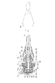
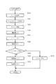
図1は本発明の盗難防止装置の一実施例を示す正面図である。図2はロックプレートと連結紐を示す平面図、図3は図2のA−A断面図、図4は図1のB−B断面図である。図5は同盗難防止装置の構成図、図6はトランスポンダを示す構成図である。図7は同盗難防止装置の動作を示すフローチャートである。尚、本実施の形態1の説明において、括弧内の符号は図7のフローチャートの符号に対応している。
【0016】
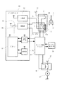
本実施の形態1に係る盗難防止装置は、小型船舶等のバーハンドル50に設けられたスイッチケース7と、スイッチケース7に設けられたエンジン停止スイッチ1およびエンジン始動スイッチ6、エンジン停止スイッチ1のロックプレート装着部1aに着脱自在に嵌まるロック部材であるロックプレート2、ロックプレート2に内蔵されたトランスポンダ40、トランスポンダ40と無線信号をやりとりするアンテナ3、トランスポンダ40に記憶されたキー情報を照合してエンジン始動を制御するイモビライザ30等から構成されている。
【0017】
図1において、スイッチケース7は、小形船舶等のバーハンドル50に設けられ、図4に示すように、前後二つ割りのケースを組み合せて構成されるもので、上部に押しボタン式のエンジン始動スイッチ6が設けられると共に、下部にはロックプレート2が着脱自在に嵌まるエンジン停止スイッチ1が設けられている。エンジン停止スイッチ1は、図4に示すように、ロックプレート2が嵌まるロックプレート装着部1aと、ロックプレート装着部1aに当接して設けられたスイッチユニット1bとから構成されていて、スイッチケース7の下部にロックプレート装着部1aを突出させた状態で取り付けられている。
【0018】
ロックプレート装着部1aは、略円筒状の作動子21と、作動子21と同軸に設けられたボタン22と、コイルバネ25,26等から構成されている。作動子21は、一端にフランジ状の太径部21aが形成されると共に、他端に細径部21bが形成された略円筒状をなし、太径部21aをスイッチケース7の下部から運転者側(図4の左方向)に突出させた状態で、プレート24を介してスイッチケース7内壁との間にコイルバネ26を設けることにより、コイルバネ26にて常時スイッチケース7に向けて付勢された状態で摺動可能に設けられている。ボタン22は、作動子21と同軸に設けられた円柱状で、作動子21の太径部21aとの間にブーツ23を介してコイルバネ25を設けることにより、コイルバネ25にて常時運転者側に付勢された状態で摺動可能に設けられている。なお、止め輪29は、ボタン22の抜け止め用である。
【0019】
スイッチユニット1bは、棒状の作動子15と、作動子15に取り付けられた板状の可動接触子16と、可動接触子16の一方の面に対向して端子台18上に設けられた第一固定接点17aと、可動接触子16の他方の面に対向して設けられた第二固定接点17bと、可動接触子16を第二固定接点17bに圧接する方向に付勢するコイルバネ20と、可動接触子16と第一固定接点17aとが接触した際に所定の接触圧を得るためのコイルバネ19と、作動子15が摺動自在に支持される略円筒状のインナーケース14と、インナーケース14の外周に被せられるアウターケース13と、アウターケース13とインナーケース14との間に一端が挟持されると共に、他端がボタン22に当接して設けられたブーツ12とから構成されている。
【0020】
アンテナ3は、コイル状で、スイッチケース7の運転者側の内壁に隣接して設けられていて、後述するイモビライザ30の無線部35に接続されている。
【0021】
エンジン始動スイッチ6は、合成樹脂製のボタン27と、ボタン27の開口部を防水するブーツ28と、スイッチユニット11とから構成されるもので、ボタン27を押圧することにより、スイッチユニット11がオンになるものである。なお、スイッチユニット11の内部構造は、スイッチユニット1bと略同一であるため、詳細な説明は省略する。
【0022】
ロックプレート2は、合成樹脂を射出成形して厚板状に作製されるもので、図2に示すように、先端部に略U字状、または、略V字状の切欠2aを有し、その内面には作動子21の細径部21bの外径と同じ円弧2cが形成されると共に、他端にはコイル状の連結紐4の一端が接続されている。連結紐4の他端には腕輪5が取り付けられており、小型船舶等の運転者は、腕輪5に手首を通すことにより、連結紐4を介してロックプレート2と連結されるものである。また、ロックプレート2の中央部には図3に示すように方形の凹部2bが形成され、凹部2bには、トランスポンダ40が嵌め込まれていて、この状態で凹部2bにエポキシ樹脂やウレタン樹脂等の熱硬化性樹脂から成る埋栓2eを充填することにより、抜け止めがなされるものである。
【0023】
一方、イモビライザ30は、ロックプレート2に内蔵されたトランスポンダ40との間で無線通信を行い、トランスポンダ40から送られるキー情報を基に、ロックプレート2がその小型船舶等に固有のものであるかどうかを識別し、盗難を防止するための装置である。
【0024】
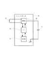
イモビライザ30は、図5に示すように、CPU(Central Processing Unit)31、電源部32、EEPROM(Electrically Erasable and Programmable Read Only Memory)33、通信インターフェース34、無線部35により構成されている。CPU31は、中央演算装置であって、イモビライザ30全体の動作を制御するものである。電源部32は、イモビライザ30が動作するための直流電圧をバッテリ37から作り出すためのものである。なお、バッテリ37は、エンジン始動スイッチ6と第一固定接点17aを介して電源部32に接続されている。EEPROM33は、CPU31に接続された記憶手段であり、不揮発性である。なお、本実施の形態においては、EEPROM33を記憶手段として使用しているが、不揮発性の記憶手段であればこれに限られるものではなく、例えば、EPROM(Erasable and Programmable Read Only Memory)やOTP(One Time Programmable read only memory)等が使用可能である。通信インターフェース34は、CPU31と、小型船舶等のエンジンの始動や停止を制御する装置であるエンジン制御ユニット36とが通信するための仲介役であり、両者間の信号レベルや信号形式を整合させるものである。
【0025】
なお、本実施の形態においては、エンジン制御ユニット36と通信インタフェース34との間の通信は、シリアル信号(例えばRS−232C準拠の信号)を使用している。しかしながら、エンジン制御ユニット36と通信インタフェース34との間の通信信号は、これに限られるものではなく、レベルの高低だけのI/O信号であっても差し支えない。なお、CPU31と通信インターフェース34とはバスにより接続されている。
【0026】
無線部35は、CPU31から送られてくる情報を変復調するものであり、変調された無線信号は、スイッチケース7に設けられたアンテナ3から図6に示すトランスポンダ40のアンテナ41に送信されると共に、トランスポンダ40から返信された無線信号を、アンテナ3で受信して復調し、復調した信号をCPU31に送るものである。
【0027】
一方、トランスポンダ40は、イモビライザ30から送られる無線信号を基に動作し、その無線信号に対しての回答となる信号を無線信号としてイモビライザ30に返信するものである。
【0028】
トランスポンダ40は、図6に示すように、イモビライザ30から送られる無線信号を受信し、かつ、トランスポンダ40側からキー情報を返信するためのアンテナ41と、無線信号を変復調するための無線部42と、トランスポンダ40の制御を行うIC43と、固有のキー情報を格納する不揮発性の記憶手段であるEEPROM44と、二次電池に相当するコンデンサ45とから構成され、これらを合成樹脂で所定の形状に成形したもので、従来公知のものと同一である。
【0029】
エンジン制御ユニット36は、通信インターフェース34と、エンジン停止スイッチ1の第一固定接点17aと、小形船舶等のエンジン点火回路38に接続されていて、エンジン停止スイッチ1の第一固定接点17aが短絡されている時に、エンジンを失火させるものである。
【0030】
また、スタータリレー46は、小形船舶等のバッテリ37およびセルモータ47に接続され、エンジン制御ユニット36によって制御されるものである。
【0031】
本実施の形態1に係る小形船舶等の盗難防止装置の動作は、次の通りである。ロックプレート2がロックプレート装着部1aに装着されていない状態では、エンジン停止スイッチ1のスイッチユニット1bは、第一固定接点17aが可動接触子16にて短絡されているので、エンジン制御ユニット36によってエンジン点火回路38が点火しない状態にある。同時に、スイッチユニット1bは、第二固定接点17b間が開放されているため、エンジン始動スイッチ6のボタン27を押しても、イモビライザ30の電源の投入が不可能であると共に、セルモータ47も回転しない。これにより、メインスイッチを廃止した際に、いたずらによる操作で、小形船舶等のバッテリ37が消耗することが防止されるものである。
【0032】
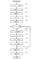
この状態から、小形船舶等を運転する場合、運転者は、まず、連結紐4の腕輪5を自分の手首に通し、次いでロックプレート2の切欠2aをエンジン停止スイッチ1のロックプレート装着部1aに押し込み、装着する(S100)。この時、切欠2aの先端には図3に示すように傾斜面2dが形成されているため、切欠2aをロックプレート装着部1aの径方向から押し込むだけで作動子21がコイルバネ26に抗して図4の左方向に自動的に移動するので、無理なく装着することができる。また、切欠2aの内面は、作動子21の細径部21bの外径と同じ円弧2cに形成されていることから、円弧2cと細径部21bとが係合し、軽く引っ張った程度では抜けることはない。
【0033】
ロックプレート2がロックプレート装着部1aに取り付けられると、スイッチユニット1bの作動子15がコイルバネ20の弾性力で押し上げられるので、可動接触子16が第一固定接点17aから離脱して第二固定接点17bに圧接し、エンジン制御ユニット36のエンジン失火状態が解除されると共に、イモビライザ30の電源投入が可能になる。
【0034】
次いで、運転者がエンジン始動スイッチ6のボタン27を押す(S101)と、スイッチユニット11がオンになり、イモビライザ30の電源部32にバッテリ37が接続され、所定の電圧が電源部32から出力され(S102)、CPU31がオンされる(S103)ことによりイモビライザ30が動作を開始する。イモビライザ30が動作を開始すると、CPU31は、無線部電源スイッチ48により無線部35をオンする(S104)。これにより、無線部35は、アンテナ3からトランスポンダ40に質問電波を送信する。
【0035】
トランスポンダ40側では、イモビライザ30からの質問電波をアンテナ41で受信して無線部42を動作させると共に、コンデンサ45を充電する。これにより、コンデンサ45は、イモビライザ30の無線部35から送られる電波により二次電池として充電され、トランスポンダ40を動作させる。そして、トランスポンダ40は、EEPROM44に記憶された固有のキー情報を無線部42およびアンテナ41を介してイモビライザ30に返信する。イモビライザ30は、トランスポンダ40からのキー情報をアンテナ3で受信すると、CPU31において、キー情報とEEPROM33に予め記憶された暗号情報とを比較する(S105)。CPU31は、予め記憶された暗号情報とトランスポンダ40から受信したキー情報とが一致した場合、通信インターフェース34を介してエンジン制御ユニット36にエンジン始動許可信号を送る。
【0036】
エンジン制御ユニット36は、該エンジン始動許可信号を受けてエンジン点火回路38を点火可能にする(S106)と共に、スタータリレー46を動作させ(S107)てセルモータ47を回転させる(S108)。これにより、小形船舶等のエンジンが始動する(S109)。
【0037】
なお、エンジン制御ユニット36は、エンジンが始動した際にエンジン始動信号を発生させる。CPU31は、通信インターフェース34を介して該エンジン始動信号を受信すると、無線部電源スイッチ48をオフして無線部35を停止させる(S110)と共に、電源部32をオフし(S111)イモビライザ30全体を休止させる。
【0038】
この状態で、運転者は、小形船舶等を運転することができる。そして、不測の事態により運転者が小型船舶等から落水すると、連結紐4に引っぱられてロックプレート2がエンジン停止スイッチ1のロックプレート装着部1aから離脱する。ロックプレート2が離脱すると、作動子21は、コイルバネ26の弾性力でスイッチケース7内にボタン22と共に没入する。コイルバネ26の弾性力は、スイッチユニット1bのコイルバネ19,20の弾性力よりも十分大きく設定されている事から、ボタン22の先端がブーツ12を介して作動子15を押し込み、可動接触子16を第一固定接点17aに圧接させる。これにより、所定の回路が形成され、エンジン制御ユニット36は、エンジンを失火させて停止させる。
【0039】
この状態から、再度エンジンを始動するためには、ロックプレート2をロックプレート装着部1aに再度装着し、エンジン始動スイッチ6のボタン27を押せばよい。また、ロックプレート2が装着された状態においても、運転者がエンジン停止スイッチ1のボタン22を押し込むと、可動接触子16が第一固定接点17aに圧接するので、エンジン制御ユニット36は、エンジンを失火させ、前記と同様にエンジンが停止する。
【0040】
尚、本実施の形態においては、トランスポンダ40をロックプレート2の凹部2bに埋め込み、熱硬化性樹脂からなる埋栓2eを充填して蓋をする形態としたが、トランスポンダ40をロックプレート2に直接インサート成形してもよいし、凹部2bを適宜の蓋部材で閉塞するようにしても良い。
【0041】
また、エンジン停止スイッチ1は、ロックプレート装着部1aとスイッチユニット1bとが別体のものを示したが、両者を一体化してもよいし、アンテナ3をエンジン停止スイッチ1に直接取り付けてもよい。
【0042】
また、本実施の形態では、エンジン始動スイッチ6を用いた場合の接続及び動作を説明したが、エンジン始動スイッチ6を用いない接続も可能である。例えば、バッテリ37を有し、セルモータ47を有していない雪上車等の場合である。
【0043】
具体的には、最初にロックプレート2がロックプレート装着部1aに装着されたとき、第二固定接点17bがオンして、イモビライザ30がバッテリ37と接続され動作を開始するように接続する。キー情報の比較作業が終了した後は、CPU31の制御により、無線部35と電源部32とをオフする。電源部32がオフされたことにより、CPU31自身もオフすることになり、イモビライザ30の動作は終了する。
【0044】
(実施の形態2)
図8の(a)は本発明の盗難防止装置の他の実施例を示す断面図、(b)は正面図である。図9はプラグと連結紐を示す平面図である。図10は同使用状態を示す断面図である。図11は同盗難防止装置の構成図、図12は同盗難防止装置の動作を示すフローチャートである。尚、本実施の形態2の説明において、括弧内の符号は図12のフローチャートの符号に対応している。
【0045】
本実施の形態2に係る盗難防止装置は、雪上車等の操作パネル51に設けられたエンジン停止スイッチ65、エンジン停止スイッチ65のナット67に着脱自在に嵌まるロック部材であるプラグ60、プラグ60に内蔵されたトランスポンダ40、トランスポンダ40と無線信号をやりとりするアンテナ3、トランスポンダ40に記憶されたキー情報を照合してエンジン停止を制御するイモビライザ30等から構成されている。
【0046】
図8において、エンジン停止スイッチ65は、雪上車等の操作パネル51に設けられ、円筒状で細径部66aと太径部66bとを有するスイッチケース66と、細径部66aの端部に螺嵌されたナット67と、細径部66a内に摺動自在に納められた軸68と、太径部66bを封止する端子台72とから構成されている。ナット67は、軸方向に貫通する案内孔67bが穿設され、外周中央部にくびれ67cを有すると共に、くびれ67cから突出し先端に向かって徐々に縮径する係止部67aを備えている。尚、係止部67aの形状は、口述するプラグ60のキャップ61の内側に形成されたホール61aと雄雌の関係にある。
【0047】
軸68は、中央よりわずかにナット67よりの位置に凸部68aを備えている。スイッチケース66の太径部66bの内部の細径部66a側には、ワッシャ69が挿嵌されており、端子台72の端部によりスイッチケース66の内面に押圧固定されている。尚、軸68の端部68cがワッシャ69を貫通し、太径部66b方向にわずかに突出している。ワッシャ69と軸68の凸部68aとの間にはコイルバネ74が配置されており、軸68がナット67方向に付勢されている。この付勢された状態で、軸68のナット67側の端部68bは、ナット67の案内孔67bよりわずかに陥没した位置に配置されている。
【0048】
端子台72は、円筒で一端が塞がれたキャップ状をしている。端子台72の他端側には、2枚の端子板71a,71bが上下に平行して設けられている。それぞれの端子板71a,71bの端部は、端子台72を貫通し外側に突出している。この端子板71a,71bには、コード73が半田付けされており、そのコード73はスイッチケース66から伸びるコード固定具73aに固定されている。端子板71a,71bと端子台72の内底面との間には、金属製で上下に突起状の接点70a,70bを有する接触板70が設けられ、台形型のコイルバネ75の弾性力によって、常時端子板71a,71bに接触するように付勢されている。
【0049】
アンテナ3は、コイル状で、スイッチケース66の細径部66aの外周に設けられたドーナッツ状のアンテナケース3a内に納められ、イモビライザ30の無線部35に接続されている。
【0050】
尚、エンジン停止スイッチ65を操作パネル51に装着するには、まず、ナット67をスイッチケース66から取り除いた状態で、操作パネル51の裏面から表面に向かってスイッチケース66の細径部66aを差込む。そして、操作パネル51の表面に突出した細径部66aの端部にナット67を螺嵌する。このことにより、エンジン停止スイッチ65は、操作パネル51をアンテナケース3aとナット67とで挟み込んだ状態で、操作パネル51に固定される。
【0051】
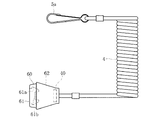
プラグ60は、図9及び図10に示すように、合成樹脂製のプラグ本体61及びキャップ62、コイル状の連結紐4及びキャップ62内に納められたトランスポンダ40とにより構成される。プラグ本体61は駒状で、端部にエンジン停止スイッチ65のナット67の係止部67aと雄雌関係になるホール61aが形成されている。ホール61aの内底面には、ナット67の案内孔67bに挿入可能な径の突起61bが設けられている。尚、プラグ本体61は、ナット67の係止部67aにホール61aが被嵌した状態で固定可能で、且つ、連結紐4を強く引くことによりプラグ本体61がナット67から離脱可能な程度の弾性を有している。
【0052】
また、プラグ本体61のホール61aとは反対側の外周には、椀状のキャップ62が被嵌されている。キャップ62は底部にトランスポンダ40が封止されている。また、プラグ60には、連結紐4の一端が接続されている。連結紐4の他端にはフック5aが取り付けられており、雪上車等の運転者は、フック5aをベルト等に引っかけることにより、連結紐4を介してプラグ60と連結される。
【0053】
エンジン制御ユニット36は、エンジン停止スイッチ65の端子板71a,71bと接続されていて、端子板71a,71bが短絡されている時に、エンジン10を失火させるものである。
リコイルスタータ39は、エンジン10の手動始動装置であって、始動用ロープを自動的にケース内に巻き取る構造を有するロープ始動装置である。発電機49は、エンジン10の回転により発電を行い、発電された電気はイモビライザ30の電源部32に送られる。尚、本実施の形態2において説明する雪上車は、バッテリを搭載していない機種である。また、イモビライザ30、トランスポンダ40、エンジン制御ユニット36等の構成及び機能については、すでに実施の形態1において説明したので、ここでは説明を省略する。
【0054】
本実施の形態2に係る雪上車等の盗難防止装置の動作は、次の通りである。
プラグ60がナット67に装着されていない状態では、エンジン停止スイッチ65の端子板71aと端子板71bとは短絡されているので、エンジン制御ユニット36によってエンジン点火回路38が点火しない状態にある。
【0055】
この状態から、雪上車等を運転する場合、運転者は、まず、連結紐4のフック5aを自分のベルト等の身体部分に掛け、次いで図10の矢印aに示すようにプラグ60をエンジン停止スイッチ65のナット67に装着する(S200)。プラグ本体61は、ナット67の係止部67aにホール61aが被嵌した状態で固定可能な弾性を有しているため、手でプラグ60を押さえるだけでナット67に装着可能である。
【0056】
プラグ60がナット67に装着されると、プラグ本体61の突起61bが、ナット67の案内孔67bを通って軸68の端部68bを押圧し、軸68が摺動する(矢印b)。軸68が摺動すると、接触板70が押されて端子板71aと端子板71bから離脱する。そして、端子板71aと端子板71bとが開放され、エンジン制御ユニット36のエンジン失火状態が解除され、エンジン始動可能状態となる。
【0057】
次いで、運転者がリコイルスタータ39を引く(S201)とエンジン10が回転を始める(S202)と共に、発電機49も発電を始め、イモビライザ30の電源部32に電気が供給され電源部32がオンする(S203)。そして、所定の電圧が電源部32から出力され、CPU31がオンされる(S204)ことによりイモビライザ30が動作を開始する。イモビライザ30が動作を開始すると、CPU31は、無線部電源スイッチ48により無線部35をオンする(S205)。これにより、無線部35は、アンテナ3からトランスポンダ40に質問電波を送信する。
【0058】
トランスポンダ40側では、イモビライザ30からの質問電波をアンテナ41で受信して無線部42を動作させると共に、コンデンサ45を充電する。これにより、コンデンサ45は、イモビライザ30の無線部35から送られる電波により二次電池として充電され、トランスポンダ40を動作させる。そして、トランスポンダ40は、EEPROM44に記憶された固有のキー情報を無線部42およびアンテナ41を介してイモビライザ30に返信する。イモビライザ30は、トランスポンダ40からのキー情報をアンテナ3で受信すると、CPU31において、キー情報とEEPROM33に予め記憶された暗号情報とを比較する(S206)。
【0059】
CPU31は、予め記憶された暗号情報とトランスポンダ40から受信したキー情報とが一致した場合、無線部電源スイッチ48をオフして無線部35を停止させる(S207)と共に、電源部32をオフし(S208)イモビライザ30全体を休止させる。
【0060】
この状態で、運転者は、雪上車等を運転することができる。そして、不測の事態により運転者が雪上車等から転落すると、連結紐4に引っぱられてプラグ60がエンジン停止スイッチ65のナット67から離脱する。プラグ60が離脱すると、軸68は、コイルバネ74の弾性力で摺動し、接触板70によって端子板71aと端子板71bとが短絡される。これにより、エンジン制御ユニット36は、エンジンを失火させて停止させる。
【0061】
予め記憶された暗号情報とトランスポンダ40から受信したキー情報とが一致しなかった場合、CPU31は、エンジン制御ユニット36に対し、エンジン停止の信号を送りエンジン10を停止させる(S210)。エンジン10が停止すると、発電機49からの電気の供給が無くなるので、イモビライザ30も必然的に動作を停止する。
【0062】
本実施の形態1及び2によれば、不測の事態にエンジン10を停止させるためのロック部材であるロックプレート2及びプラグ60にトランスポンダ40が内蔵されている。そして、イモビライザ30がトランスポンダ40のキー情報を読み取り、キー情報とイモビライザ30に予め記憶された暗号情報とを比較する。そして、両者が一致した際にイモビライザ30がエンジン10の始動を許可し、又はエンジン始動継続を許可する。すなわち、ロックプレート2及びプラグ60が、不測の事態でのエンジン停止と盗難防止という2つの機能を有しているため、シリンダ錠やマグネット錠を用いた従来のメインスイッチが廃止でき、運転者が扱うのはロック部材のみでよくキー管理の負担が軽減される。
また、膨大な組み合わせのキー情報を判別可能なイモビライザ30を用いることにより、キー種を増やすことが可能であり、不正な解錠行為に対する抵抗力を高めることができる。
【0063】
【発明の効果】
請求項1の発明によれば、不測の事態にエンジンを停止させるためのロック部材にトランスポンダが内蔵されている。そして、イモビライザがトランスポンダのキー情報を読み取り、キー情報とイモビライザに予め記憶された暗号情報とを比較し、両者が一致した際にイモビライザがエンジンの始動を許可する。すなわち、ロック部材が、不測の事態でのエンジン停止と盗難防止という2つの機能を有しているため、シリンダ錠やマグネット錠を用いた従来のメインスイッチが廃止でき、運転者が扱うのはロック部材のみでよくキー管理の負担が軽減する。
また、膨大な組み合わせのキー情報を判別可能なイモビライザを用いることにより、キー種を増やすことが可能であり、不正な解錠行為に対する抵抗力を高めることができる。
【0064】
請求項3の発明によれば、ロック部材がロック部材装着部に装着されている場合のみ、エンジン始動スイッチがイモビライザの電源オン/オフを制御し得る。このため、メインスイッチを廃止した際に、ロック部材が装着されていない状態では、第三者のいたずらによる操作で小形船舶等のバッテリが消耗することを防止できる。
【図面の簡単な説明】
【図1】本発明の盗難防止装置の一実施例を示す正面図である。
【図2】ロックプレートと連結紐を示す平面図である。
【図3】図2のA−A断面図である。
【図4】図1のB−B断面図である。
【図5】同盗難防止装置の構成図である。
【図6】トランスポンダを示す構成図である。
【図7】同盗難防止装置の動作を示すフローチャートである。
【図8】(a)は本発明の盗難防止装置の他の実施例を示す断面図、(b)は正面図である。
【図9】プラグと連結紐を示す平面図である。
【図10】同使用状態を示す断面図である。
【図11】同盗難防止装置の構成図である。
【図12】同盗難防止装置の動作を示すフローチャートである。
【符号の説明】
1,65・・・・・・・エンジン停止スイッチ
1a・・・・・・・・・ロックプレート装着部
1b・・・・・・・・・スイッチユニット
2・・・・・・・・・・ロックプレート
2a・・・・・・・・・切欠
2b・・・・・・・・・凹部
2c・・・・・・・・・円弧
3・・・・・・・・・・アンテナ
4・・・・・・・・・・連結紐
5・・・・・・・・・・腕輪
6・・・・・・・・・・エンジン始動スイッチ
7,66・・・・・・・スイッチケース
10・・・・・・・・・エンジン
11・・・・・・・・・スイッチユニット
21・・・・・・・・・作動子
22・・・・・・・・・ボタン
30・・・・・・・・・イモビライザ
31・・・・・・・・・CPU
32・・・・・・・・・電源部
33・・・・・・・・・EEPROM
34・・・・・・・・・通信インターフェース
35・・・・・・・・・無線部
36・・・・・・・・・エンジン制御ユニット
40・・・・・・・・・トランスポンダ
41・・・・・・・・・アンテナ
42・・・・・・・・・無線部
43・・・・・・・・・IC
44・・・・・・・・・EEPROM
45・・・・・・・・・コンデンサ
48・・・・・・・・・無線部電源スイッチ
50・・・・・・・・・バーハンドル
51・・・・・・・・・操作パネル
60・・・・・・・・・プラグ
61・・・・・・・・・プラグ本体
61a・・・・・・・・ホール
61b・・・・・・・・突起
66・・・・・・・・・ケース
68・・・・・・・・・軸
70・・・・・・・・・接触板
71a,71b・・・・端子板
72・・・・・・・・・端子台[0001]
BACKGROUND OF THE INVENTION
The present invention relates to an anti-theft device used for small ships such as PWC (Personal Water Craft) and motor boats, snow vehicles, and the like.
[0002]
[Prior art]
2. Description of the Related Art Conventionally, in a small ship, a snow vehicle, and the like, a main switch (power switch) using a cylinder lock or a magnet lock is provided in order to prevent a person other than a regular driver from operating illegally.
[0003]
A regular driver unlocks the main switch with a plate key or a magnet key and turns on the power of a small vessel, etc., and then turns on the engine start switch provided on the operation panel or bar handle to turn on the cell motor. Rotate and start the engine.
[0004]
Further, an operation panel or a bar handle of a small ship or the like is disclosed in Japanese Utility Model Publication No. 54-11466, for example, in order to stop the engine when a driver falls due to an unexpected situation during traveling. A stop switch is provided.
[0005]
The engine stop switch is a switch configured such that a movable contact that can be slidably pressed against a fixed contact is always pressed by a spring, and is disposed between the fixed contact and the movable contact. By inserting a spacer called a lock plate in a removable manner and pulling out the lock plate from the switch via a connecting string fixed to the driver's body in an emergency, a fixed contact and a movable contact Are pressed and the switch is turned on to stop an engine such as a small vessel.
[0006]
The main switch must be made of synthetic resin for the cylinder lock and the magnet lock for the purpose of rust prevention and freezing prevention. Therefore, the main switch has sufficient strength against destruction using tools such as drills and drivers. It was difficult to do.
In addition, it is difficult to secure a sufficient combination of key types with mechanical cylinder locks and magnet locks.
[0007]
In order to solve such a problem, in a two-wheeled vehicle and a four-wheeled vehicle, a radio wave transponder is built in the plate key, an immobilizer is built in the cylinder lock, and key information stored in the transponder is stored in the immobilizer. Is read in a non-contact manner and compared with pre-stored encrypted information, and is configured to allow the engine to start only when they match, to counter the vandalism and to secure the key type The method has been put into practical use.
[0008]
[Problems to be solved by the invention]
As described above, in a conventional small vessel or the like, the driver only has to remove the plate key in order to prevent theft. However, if the lock plate for stopping the engine is stolen in the unlikely event, even a regular driver cannot drive. For this reason, when the driver leaves the small vessel or the like, it is necessary to remove both the plate key and the lock plate, and its management is complicated.
[0009]
The present invention has been made in view of such circumstances. The purpose of the present invention is to make it possible to abolish the conventional main switch. By increasing the number of key types, the resistance to unauthorized unlocking is increased. An object of the present invention is to provide an anti-theft device that can prevent a battery from being consumed due to a mischief by a third party.
[0010]
[Means for Solving the Problems]
The anti-theft device according to
[0011]
According to a second aspect of the present invention, there is provided an antitheft device comprising an engine start switch for controlling power on / off of the immobilizer.
[0012]
The anti-theft device according to
[0013]
The anti-theft device according to
[0014]
DETAILED DESCRIPTION OF THE INVENTION
Hereinafter, embodiments of the present invention will be specifically described with reference to the drawings. 1 to 7 are drawings showing a first embodiment, and FIGS. 8 to 12 are drawings showing a second embodiment.
[0015]
(Embodiment 1)
FIG. 1 is a front view showing an embodiment of the antitheft device of the present invention. 2 is a plan view showing the lock plate and the connecting string, FIG. 3 is a cross-sectional view taken along line AA in FIG. 2, and FIG. 4 is a cross-sectional view taken along line BB in FIG. FIG. 5 is a block diagram showing the antitheft device, and FIG. 6 is a block diagram showing the transponder. FIG. 7 is a flowchart showing the operation of the antitheft device. In the description of the first embodiment, the reference numerals in parentheses correspond to the reference numerals in the flowchart of FIG.
[0016]
The antitheft device according to the first embodiment includes a
[0017]
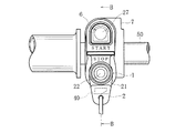
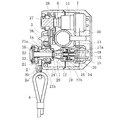
In FIG. 1, a
[0018]
The lock plate mounting portion 1a includes a substantially
[0019]
The
[0020]
The
[0021]
The
[0022]
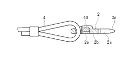
The
[0023]
On the other hand, the
[0024]
As shown in FIG. 5, the
[0025]
In the present embodiment, communication between the
[0026]
The
[0027]
On the other hand, the
[0028]
As shown in FIG. 6, the
[0029]
The
[0030]
The
[0031]
The operation of the antitheft device such as a small vessel according to the first embodiment is as follows. In a state where the
[0032]
From this state, when driving a small vessel or the like, the driver first passes the
[0033]
When the
[0034]
Next, when the driver presses the
[0035]
On the
[0036]
The
[0037]
The
[0038]
In this state, the driver can drive a small vessel or the like. When the driver falls from a small ship or the like due to an unexpected situation, the
[0039]
In order to start the engine again from this state, the
[0040]
In this embodiment, the
[0041]
Further, the
[0042]
Further, in the present embodiment, the connection and operation when the
[0043]
Specifically, when the
[0044]
(Embodiment 2)
FIG. 8A is a sectional view showing another embodiment of the antitheft device of the present invention, and FIG. 8B is a front view. FIG. 9 is a plan view showing the plug and the connecting string. FIG. 10 is a cross-sectional view showing the same use state. FIG. 11 is a configuration diagram of the antitheft device, and FIG. 12 is a flowchart showing the operation of the antitheft device. In the description of the second embodiment, the reference numerals in parentheses correspond to the reference numerals in the flowchart of FIG.
[0045]
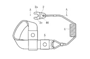
The antitheft device according to the second embodiment includes an
[0046]
In FIG. 8, the
[0047]
The
[0048]
The
[0049]
The
[0050]
In order to attach the
[0051]
As shown in FIGS. 9 and 10, the
[0052]
A hook-shaped
[0053]
The
The
[0054]
The operation of the antitheft device such as a snow vehicle according to the second embodiment is as follows.
When the
[0055]
When driving a snow vehicle or the like from this state, the driver first hangs the
[0056]
When the
[0057]
Next, when the driver pulls the recoil starter 39 (S201), the
[0058]
On the
[0059]
When the encryption information stored in advance matches the key information received from the
[0060]
In this state, the driver can drive a snow vehicle or the like. When the driver falls from a snow vehicle or the like due to an unexpected situation, the
[0061]
When the encryption information stored in advance and the key information received from the
[0062]
According to the first and second embodiments, the
Further, by using the
[0063]
【The invention's effect】
According to the first aspect of the present invention, the transponder is built in the lock member for stopping the engine in an unexpected situation. Then, the immobilizer reads the transponder key information, compares the key information with the encryption information stored in advance in the immobilizer, and when the two match, the immobilizer permits the engine to start. In other words, since the lock member has two functions of stopping the engine and preventing theft in unexpected situations, the conventional main switch using the cylinder lock and magnet lock can be abolished, and the driver handles the lock. The key management burden can be reduced by using only the material.
Further, by using an immobilizer capable of discriminating a large number of combinations of key information, it is possible to increase the number of key types and increase resistance to an unauthorized unlocking action.
[0064]
According to the invention of
[Brief description of the drawings]
FIG. 1 is a front view showing an embodiment of an antitheft device according to the present invention.
FIG. 2 is a plan view showing a lock plate and a connecting string.
3 is a cross-sectional view taken along the line AA in FIG.
4 is a cross-sectional view taken along the line BB in FIG.
FIG. 5 is a configuration diagram of the antitheft device.
FIG. 6 is a configuration diagram showing a transponder.
FIG. 7 is a flowchart showing the operation of the antitheft device.
8A is a sectional view showing another embodiment of the anti-theft device of the present invention, and FIG. 8B is a front view thereof.
FIG. 9 is a plan view showing a plug and a connecting string.
FIG. 10 is a cross-sectional view showing the same use state.
FIG. 11 is a configuration diagram of the antitheft device.
FIG. 12 is a flowchart showing the operation of the antitheft device.
[Explanation of symbols]
1,65 ... Engine stop switch
1a ... Lock plate mounting part
1b ・ ・ ・ ・ ・ ・ ・ ・ ・ Switch unit
2 ... Lock plate
2a ......... Notch
2b ......... Recess
2c ... arc
3 ... Antenna
4 ・ ・ ・ ・ ・ ・ ・ ・ ・ ・ Linked string
5 ... Bangle
6 ... Engine start switch
7, 66 .... Switch case
10 .... Engine
11 .... Switch unit
21... Actuator
22 ... button
30 ... Immobilizer
31 ... CPU
32 ... Power supply
33 ... EEPROM
34 ..... Communication interface
35 ..... radio part
36 ... Engine control unit
40 ・ ・ ・ ・ ・ ・ ・ ・ ・ Transponder
41 ... Antenna
42 ..... Radio Department
43 ... IC
44 .... EEPROM
45 ・ ・ ・ ・ ・ ・ ・ ・ ・ Capacitor
48 ..... Wireless unit power switch
50 ・ ・ ・ ・ ・ ・ ・ ・ ・ Bar handle
51 ..... Operation panel
60 ..... Plug
61 ..... Plug body
61a ... Hall
61b ... Projection
66 ..... Case
68 ・ ・ ・ ・ ・ ・ ・ ・ ・ Shaft
70 ... Contact plate
71a, 71b... Terminal board
72 ... Terminal block
Claims (4)
Priority Applications (1)
| Application Number | Priority Date | Filing Date | Title |
|---|---|---|---|
| JP2000091422A JP3663333B2 (en) | 1999-09-09 | 2000-03-29 | Anti-theft device |
Applications Claiming Priority (3)
| Application Number | Priority Date | Filing Date | Title |
|---|---|---|---|
| JP11-255340 | 1999-09-09 | ||
| JP25534099 | 1999-09-09 | ||
| JP2000091422A JP3663333B2 (en) | 1999-09-09 | 2000-03-29 | Anti-theft device |
Publications (2)
| Publication Number | Publication Date |
|---|---|
| JP2001146148A JP2001146148A (en) | 2001-05-29 |
| JP3663333B2 true JP3663333B2 (en) | 2005-06-22 |
Family
ID=26542154
Family Applications (1)
| Application Number | Title | Priority Date | Filing Date |
|---|---|---|---|
| JP2000091422A Expired - Fee Related JP3663333B2 (en) | 1999-09-09 | 2000-03-29 | Anti-theft device |
Country Status (1)
| Country | Link |
|---|---|
| JP (1) | JP3663333B2 (en) |
Families Citing this family (23)
| Publication number | Priority date | Publication date | Assignee | Title |
|---|---|---|---|---|
| KR100475683B1 (en) * | 2001-12-27 | 2005-03-10 | 씨멘스 오토모티브 주식회사 | Immobilizer starting apparatus of car |
| JP4137657B2 (en) * | 2003-02-06 | 2008-08-20 | 株式会社東海理化電機製作所 | Engine start / stop switch device |
| JP4281994B2 (en) | 2003-03-06 | 2009-06-17 | 朝日電装株式会社 | Engine control device |
| JP2004270607A (en) | 2003-03-11 | 2004-09-30 | Asahi Denso Co Ltd | Engine control device |
| JP4248274B2 (en) | 2003-03-11 | 2009-04-02 | 朝日電装株式会社 | Engine control device |
| JP4562408B2 (en) | 2003-03-27 | 2010-10-13 | 株式会社クボタ | Vehicle anti-theft system |
| JP4409194B2 (en) | 2003-04-02 | 2010-02-03 | 朝日電装株式会社 | Engine control devices such as small propulsion boats |
| JP4782031B2 (en) * | 2007-02-01 | 2011-09-28 | 朝日電装株式会社 | Engine start switch device |
| JP4814117B2 (en) * | 2007-02-01 | 2011-11-16 | 朝日電装株式会社 | Switch device |
| JP5426077B2 (en) * | 2007-02-21 | 2014-02-26 | ルネサスエレクトロニクス株式会社 | Intermittent drive system |
| JP5059694B2 (en) * | 2008-06-09 | 2012-10-24 | ヤマハ発動機株式会社 | Outboard motor immobilizer receiver |
| JP2010017129A (en) * | 2008-07-10 | 2010-01-28 | Honda Motor Co Ltd | Antitheft device for equipment |
| JP5081102B2 (en) | 2008-08-22 | 2012-11-21 | ヤマハ発動機株式会社 | Ship theft deterrent device and ship equipped with the same |
| JP5081103B2 (en) | 2008-08-22 | 2012-11-21 | ヤマハ発動機株式会社 | Ship theft deterrent device and ship equipped with the same |
| JP5081101B2 (en) * | 2008-08-22 | 2012-11-21 | ヤマハ発動機株式会社 | Ship theft deterrent device and ship equipped with the same |
| JP5043789B2 (en) * | 2008-09-24 | 2012-10-10 | 株式会社東海理化電機製作所 | Switch device |
| JP4886059B2 (en) * | 2010-05-21 | 2012-02-29 | 株式会社東海理化電機製作所 | Switch device, security system |
| KR101689202B1 (en) * | 2010-12-17 | 2016-12-23 | 콘티넨탈 오토모티브 시스템 주식회사 | System and method for driving fobkey of vehicle |
| ES2645405T3 (en) * | 2015-03-05 | 2017-12-05 | Betamotor S.P.A. | Dual security anti-theft emergency device for motor vehicles without battery |
| JP6524868B2 (en) * | 2015-09-07 | 2019-06-05 | スズキ株式会社 | Outboard motor having keyless entry system |
| KR102399994B1 (en) * | 2015-10-30 | 2022-05-20 | 대우조선해양 주식회사 | Apparatus for detecting underwater radiated noise |
| US11368056B2 (en) | 2019-09-18 | 2022-06-21 | Marquardt Gmbh | Equipment systems including communication systems, communication systems, components of communication systems, and methods of operating such systems and components |
| CN110761907B (en) * | 2019-11-06 | 2021-12-28 | 西安电子工程研究所 | Forced flameout device for engine of speed boat |
-
2000
- 2000-03-29 JP JP2000091422A patent/JP3663333B2/en not_active Expired - Fee Related
Also Published As
| Publication number | Publication date |
|---|---|
| JP2001146148A (en) | 2001-05-29 |
Similar Documents
| Publication | Publication Date | Title |
|---|---|---|
| JP3663333B2 (en) | Anti-theft device | |
| JP4100570B2 (en) | Vehicle locking device | |
| US6188140B1 (en) | Immobilizer system-mounting vehicle and member used for the immobilizer system | |
| KR100756260B1 (en) | Anti-theft system for vehicle | |
| JP2008255726A (en) | Cylinder lock unit | |
| JP2009084978A (en) | Valet key storage device | |
| JP4329945B2 (en) | Engine start system | |
| JP5142389B2 (en) | Cylinder lock protector | |
| JP4555206B2 (en) | Electronic key for vehicle | |
| WO1998000319A1 (en) | Improved remote keyless entry device | |
| JP4627991B2 (en) | Cylinder lock protector | |
| JP2008254672A (en) | Engine start switch | |
| JP4012379B2 (en) | Cylinder lock protector | |
| KR0185550B1 (en) | Diesel vehicle security | |
| KR20100079603A (en) | Smart key system and management method of the same | |
| KR100209022B1 (en) | Startup key and method by which the key pin protrudes by fingerprint detection | |
| JP2010037834A (en) | Protection device for cylinder lock | |
| JP2004108196A (en) | Engine start / stop control system | |
| JP5187943B2 (en) | Cylinder lock protector | |
| JPS63199186A (en) | Burglarproof device for car | |
| JP3651043B2 (en) | Key cylinder device | |
| KR20040104124A (en) | Automatic charging apparatus of automobile keyless entry | |
| JP3924598B2 (en) | Key with built-in transponder | |
| TWI470143B (en) | Protection of the cylinder lock | |
| KR200177747Y1 (en) | Startup key with built-in modifier key |
Legal Events
| Date | Code | Title | Description |
|---|---|---|---|
| A131 | Notification of reasons for refusal |
Free format text: JAPANESE INTERMEDIATE CODE: A131 Effective date: 20041221 |
|
| A521 | Written amendment |
Free format text: JAPANESE INTERMEDIATE CODE: A523 Effective date: 20050201 |
|
| TRDD | Decision of grant or rejection written | ||
| A01 | Written decision to grant a patent or to grant a registration (utility model) |
Free format text: JAPANESE INTERMEDIATE CODE: A01 Effective date: 20050322 |
|
| A61 | First payment of annual fees (during grant procedure) |
Free format text: JAPANESE INTERMEDIATE CODE: A61 Effective date: 20050328 |
|
| R150 | Certificate of patent or registration of utility model |
Free format text: JAPANESE INTERMEDIATE CODE: R150 |
|
| FPAY | Renewal fee payment (event date is renewal date of database) |
Free format text: PAYMENT UNTIL: 20090401 Year of fee payment: 4 |
|
| FPAY | Renewal fee payment (event date is renewal date of database) |
Free format text: PAYMENT UNTIL: 20100401 Year of fee payment: 5 |
|
| FPAY | Renewal fee payment (event date is renewal date of database) |
Free format text: PAYMENT UNTIL: 20100401 Year of fee payment: 5 |
|
| FPAY | Renewal fee payment (event date is renewal date of database) |
Free format text: PAYMENT UNTIL: 20110401 Year of fee payment: 6 |
|
| FPAY | Renewal fee payment (event date is renewal date of database) |
Free format text: PAYMENT UNTIL: 20120401 Year of fee payment: 7 |
|
| FPAY | Renewal fee payment (event date is renewal date of database) |
Free format text: PAYMENT UNTIL: 20130401 Year of fee payment: 8 |
|
| FPAY | Renewal fee payment (event date is renewal date of database) |
Free format text: PAYMENT UNTIL: 20130401 Year of fee payment: 8 |
|
| FPAY | Renewal fee payment (event date is renewal date of database) |
Free format text: PAYMENT UNTIL: 20140401 Year of fee payment: 9 |
|
| R250 | Receipt of annual fees |
Free format text: JAPANESE INTERMEDIATE CODE: R250 |
|
| R250 | Receipt of annual fees |
Free format text: JAPANESE INTERMEDIATE CODE: R250 |
|
| R250 | Receipt of annual fees |
Free format text: JAPANESE INTERMEDIATE CODE: R250 |
|
| LAPS | Cancellation because of no payment of annual fees |