JP3658519B2 - Vehicle control system and vehicle control device - Google Patents
Vehicle control system and vehicle control device Download PDFInfo
- Publication number
- JP3658519B2 JP3658519B2 JP18107099A JP18107099A JP3658519B2 JP 3658519 B2 JP3658519 B2 JP 3658519B2 JP 18107099 A JP18107099 A JP 18107099A JP 18107099 A JP18107099 A JP 18107099A JP 3658519 B2 JP3658519 B2 JP 3658519B2
- Authority
- JP
- Japan
- Prior art keywords
- vehicle
- target
- distance
- preceding vehicle
- lane
- Prior art date
- Legal status (The legal status is an assumption and is not a legal conclusion. Google has not performed a legal analysis and makes no representation as to the accuracy of the status listed.)
- Expired - Fee Related
Links
- 238000012545 processing Methods 0.000 claims description 15
- 238000012937 correction Methods 0.000 claims description 14
- 238000010586 diagram Methods 0.000 description 17
- 230000033001 locomotion Effects 0.000 description 15
- 238000000034 method Methods 0.000 description 15
- 238000001514 detection method Methods 0.000 description 14
- 230000001133 acceleration Effects 0.000 description 8
- 238000004891 communication Methods 0.000 description 8
- 238000004422 calculation algorithm Methods 0.000 description 6
- 238000005259 measurement Methods 0.000 description 5
- 238000013459 approach Methods 0.000 description 3
- 230000007423 decrease Effects 0.000 description 3
- 238000004364 calculation method Methods 0.000 description 2
- 238000006073 displacement reaction Methods 0.000 description 2
- 231100001261 hazardous Toxicity 0.000 description 2
- 239000000463 material Substances 0.000 description 2
- 230000000116 mitigating effect Effects 0.000 description 2
- 230000003044 adaptive effect Effects 0.000 description 1
- 230000005540 biological transmission Effects 0.000 description 1
- 238000009795 derivation Methods 0.000 description 1
- 230000000694 effects Effects 0.000 description 1
- 238000001914 filtration Methods 0.000 description 1
- 238000002372 labelling Methods 0.000 description 1
- 238000012423 maintenance Methods 0.000 description 1
- 239000004576 sand Substances 0.000 description 1
Images


Classifications
-
- B—PERFORMING OPERATIONS; TRANSPORTING
- B60—VEHICLES IN GENERAL
- B60W—CONJOINT CONTROL OF VEHICLE SUB-UNITS OF DIFFERENT TYPE OR DIFFERENT FUNCTION; CONTROL SYSTEMS SPECIALLY ADAPTED FOR HYBRID VEHICLES; ROAD VEHICLE DRIVE CONTROL SYSTEMS FOR PURPOSES NOT RELATED TO THE CONTROL OF A PARTICULAR SUB-UNIT
- B60W30/00—Purposes of road vehicle drive control systems not related to the control of a particular sub-unit, e.g. of systems using conjoint control of vehicle sub-units
- B60W30/14—Adaptive cruise control
- B60W30/16—Control of distance between vehicles, e.g. keeping a distance to preceding vehicle
-
- B—PERFORMING OPERATIONS; TRANSPORTING
- B60—VEHICLES IN GENERAL
- B60K—ARRANGEMENT OR MOUNTING OF PROPULSION UNITS OR OF TRANSMISSIONS IN VEHICLES; ARRANGEMENT OR MOUNTING OF PLURAL DIVERSE PRIME-MOVERS IN VEHICLES; AUXILIARY DRIVES FOR VEHICLES; INSTRUMENTATION OR DASHBOARDS FOR VEHICLES; ARRANGEMENTS IN CONNECTION WITH COOLING, AIR INTAKE, GAS EXHAUST OR FUEL SUPPLY OF PROPULSION UNITS IN VEHICLES
- B60K31/00—Vehicle fittings, acting on a single sub-unit only, for automatically controlling vehicle speed, i.e. preventing speed from exceeding an arbitrarily established velocity or maintaining speed at a particular velocity, as selected by the vehicle operator
- B60K31/0008—Vehicle fittings, acting on a single sub-unit only, for automatically controlling vehicle speed, i.e. preventing speed from exceeding an arbitrarily established velocity or maintaining speed at a particular velocity, as selected by the vehicle operator including means for detecting potential obstacles in vehicle path
-
- G—PHYSICS
- G01—MEASURING; TESTING
- G01S—RADIO DIRECTION-FINDING; RADIO NAVIGATION; DETERMINING DISTANCE OR VELOCITY BY USE OF RADIO WAVES; LOCATING OR PRESENCE-DETECTING BY USE OF THE REFLECTION OR RERADIATION OF RADIO WAVES; ANALOGOUS ARRANGEMENTS USING OTHER WAVES
- G01S13/00—Systems using the reflection or reradiation of radio waves, e.g. radar systems; Analogous systems using reflection or reradiation of waves whose nature or wavelength is irrelevant or unspecified
- G01S13/88—Radar or analogous systems specially adapted for specific applications
- G01S13/93—Radar or analogous systems specially adapted for specific applications for anti-collision purposes
- G01S13/931—Radar or analogous systems specially adapted for specific applications for anti-collision purposes of land vehicles
-
- B—PERFORMING OPERATIONS; TRANSPORTING
- B60—VEHICLES IN GENERAL
- B60W—CONJOINT CONTROL OF VEHICLE SUB-UNITS OF DIFFERENT TYPE OR DIFFERENT FUNCTION; CONTROL SYSTEMS SPECIALLY ADAPTED FOR HYBRID VEHICLES; ROAD VEHICLE DRIVE CONTROL SYSTEMS FOR PURPOSES NOT RELATED TO THE CONTROL OF A PARTICULAR SUB-UNIT
- B60W50/00—Details of control systems for road vehicle drive control not related to the control of a particular sub-unit, e.g. process diagnostic or vehicle driver interfaces
- B60W50/08—Interaction between the driver and the control system
- B60W50/14—Means for informing the driver, warning the driver or prompting a driver intervention
- B60W2050/143—Alarm means
-
- B—PERFORMING OPERATIONS; TRANSPORTING
- B60—VEHICLES IN GENERAL
- B60W—CONJOINT CONTROL OF VEHICLE SUB-UNITS OF DIFFERENT TYPE OR DIFFERENT FUNCTION; CONTROL SYSTEMS SPECIALLY ADAPTED FOR HYBRID VEHICLES; ROAD VEHICLE DRIVE CONTROL SYSTEMS FOR PURPOSES NOT RELATED TO THE CONTROL OF A PARTICULAR SUB-UNIT
- B60W2552/00—Input parameters relating to infrastructure
- B60W2552/20—Road profile, i.e. the change in elevation or curvature of a plurality of continuous road segments
-
- B—PERFORMING OPERATIONS; TRANSPORTING
- B60—VEHICLES IN GENERAL
- B60W—CONJOINT CONTROL OF VEHICLE SUB-UNITS OF DIFFERENT TYPE OR DIFFERENT FUNCTION; CONTROL SYSTEMS SPECIALLY ADAPTED FOR HYBRID VEHICLES; ROAD VEHICLE DRIVE CONTROL SYSTEMS FOR PURPOSES NOT RELATED TO THE CONTROL OF A PARTICULAR SUB-UNIT
- B60W2552/00—Input parameters relating to infrastructure
- B60W2552/30—Road curve radius
-
- B—PERFORMING OPERATIONS; TRANSPORTING
- B60—VEHICLES IN GENERAL
- B60W—CONJOINT CONTROL OF VEHICLE SUB-UNITS OF DIFFERENT TYPE OR DIFFERENT FUNCTION; CONTROL SYSTEMS SPECIALLY ADAPTED FOR HYBRID VEHICLES; ROAD VEHICLE DRIVE CONTROL SYSTEMS FOR PURPOSES NOT RELATED TO THE CONTROL OF A PARTICULAR SUB-UNIT
- B60W2556/00—Input parameters relating to data
- B60W2556/45—External transmission of data to or from the vehicle
- B60W2556/50—External transmission of data to or from the vehicle of positioning data, e.g. GPS [Global Positioning System] data
-
- G—PHYSICS
- G01—MEASURING; TESTING
- G01S—RADIO DIRECTION-FINDING; RADIO NAVIGATION; DETERMINING DISTANCE OR VELOCITY BY USE OF RADIO WAVES; LOCATING OR PRESENCE-DETECTING BY USE OF THE REFLECTION OR RERADIATION OF RADIO WAVES; ANALOGOUS ARRANGEMENTS USING OTHER WAVES
- G01S13/00—Systems using the reflection or reradiation of radio waves, e.g. radar systems; Analogous systems using reflection or reradiation of waves whose nature or wavelength is irrelevant or unspecified
- G01S13/88—Radar or analogous systems specially adapted for specific applications
- G01S13/93—Radar or analogous systems specially adapted for specific applications for anti-collision purposes
- G01S13/931—Radar or analogous systems specially adapted for specific applications for anti-collision purposes of land vehicles
- G01S2013/93185—Controlling the brakes
-
- G—PHYSICS
- G01—MEASURING; TESTING
- G01S—RADIO DIRECTION-FINDING; RADIO NAVIGATION; DETERMINING DISTANCE OR VELOCITY BY USE OF RADIO WAVES; LOCATING OR PRESENCE-DETECTING BY USE OF THE REFLECTION OR RERADIATION OF RADIO WAVES; ANALOGOUS ARRANGEMENTS USING OTHER WAVES
- G01S13/00—Systems using the reflection or reradiation of radio waves, e.g. radar systems; Analogous systems using reflection or reradiation of waves whose nature or wavelength is irrelevant or unspecified
- G01S13/88—Radar or analogous systems specially adapted for specific applications
- G01S13/93—Radar or analogous systems specially adapted for specific applications for anti-collision purposes
- G01S13/931—Radar or analogous systems specially adapted for specific applications for anti-collision purposes of land vehicles
- G01S2013/932—Radar or analogous systems specially adapted for specific applications for anti-collision purposes of land vehicles using own vehicle data, e.g. ground speed, steering wheel direction
-
- G—PHYSICS
- G01—MEASURING; TESTING
- G01S—RADIO DIRECTION-FINDING; RADIO NAVIGATION; DETERMINING DISTANCE OR VELOCITY BY USE OF RADIO WAVES; LOCATING OR PRESENCE-DETECTING BY USE OF THE REFLECTION OR RERADIATION OF RADIO WAVES; ANALOGOUS ARRANGEMENTS USING OTHER WAVES
- G01S13/00—Systems using the reflection or reradiation of radio waves, e.g. radar systems; Analogous systems using reflection or reradiation of waves whose nature or wavelength is irrelevant or unspecified
- G01S13/88—Radar or analogous systems specially adapted for specific applications
- G01S13/93—Radar or analogous systems specially adapted for specific applications for anti-collision purposes
- G01S13/931—Radar or analogous systems specially adapted for specific applications for anti-collision purposes of land vehicles
- G01S2013/9321—Velocity regulation, e.g. cruise control
-
- G—PHYSICS
- G01—MEASURING; TESTING
- G01S—RADIO DIRECTION-FINDING; RADIO NAVIGATION; DETERMINING DISTANCE OR VELOCITY BY USE OF RADIO WAVES; LOCATING OR PRESENCE-DETECTING BY USE OF THE REFLECTION OR RERADIATION OF RADIO WAVES; ANALOGOUS ARRANGEMENTS USING OTHER WAVES
- G01S13/00—Systems using the reflection or reradiation of radio waves, e.g. radar systems; Analogous systems using reflection or reradiation of waves whose nature or wavelength is irrelevant or unspecified
- G01S13/88—Radar or analogous systems specially adapted for specific applications
- G01S13/93—Radar or analogous systems specially adapted for specific applications for anti-collision purposes
- G01S13/931—Radar or analogous systems specially adapted for specific applications for anti-collision purposes of land vehicles
- G01S2013/9325—Radar or analogous systems specially adapted for specific applications for anti-collision purposes of land vehicles for inter-vehicle distance regulation, e.g. navigating in platoons
-
- G—PHYSICS
- G01—MEASURING; TESTING
- G01S—RADIO DIRECTION-FINDING; RADIO NAVIGATION; DETERMINING DISTANCE OR VELOCITY BY USE OF RADIO WAVES; LOCATING OR PRESENCE-DETECTING BY USE OF THE REFLECTION OR RERADIATION OF RADIO WAVES; ANALOGOUS ARRANGEMENTS USING OTHER WAVES
- G01S13/00—Systems using the reflection or reradiation of radio waves, e.g. radar systems; Analogous systems using reflection or reradiation of waves whose nature or wavelength is irrelevant or unspecified
- G01S13/88—Radar or analogous systems specially adapted for specific applications
- G01S13/93—Radar or analogous systems specially adapted for specific applications for anti-collision purposes
- G01S13/931—Radar or analogous systems specially adapted for specific applications for anti-collision purposes of land vehicles
- G01S2013/9327—Sensor installation details
- G01S2013/93271—Sensor installation details in the front of the vehicles
-
- G—PHYSICS
- G01—MEASURING; TESTING
- G01S—RADIO DIRECTION-FINDING; RADIO NAVIGATION; DETERMINING DISTANCE OR VELOCITY BY USE OF RADIO WAVES; LOCATING OR PRESENCE-DETECTING BY USE OF THE REFLECTION OR RERADIATION OF RADIO WAVES; ANALOGOUS ARRANGEMENTS USING OTHER WAVES
- G01S7/00—Details of systems according to groups G01S13/00, G01S15/00, G01S17/00
- G01S7/02—Details of systems according to groups G01S13/00, G01S15/00, G01S17/00 of systems according to group G01S13/00
- G01S7/40—Means for monitoring or calibrating
- G01S7/4004—Means for monitoring or calibrating of parts of a radar system
- G01S7/4026—Antenna boresight
- G01S7/403—Antenna boresight in azimuth, i.e. in the horizontal plane
-
- G—PHYSICS
- G01—MEASURING; TESTING
- G01S—RADIO DIRECTION-FINDING; RADIO NAVIGATION; DETERMINING DISTANCE OR VELOCITY BY USE OF RADIO WAVES; LOCATING OR PRESENCE-DETECTING BY USE OF THE REFLECTION OR RERADIATION OF RADIO WAVES; ANALOGOUS ARRANGEMENTS USING OTHER WAVES
- G01S7/00—Details of systems according to groups G01S13/00, G01S15/00, G01S17/00
- G01S7/02—Details of systems according to groups G01S13/00, G01S15/00, G01S17/00 of systems according to group G01S13/00
- G01S7/40—Means for monitoring or calibrating
- G01S7/4052—Means for monitoring or calibrating by simulation of echoes
- G01S7/4082—Means for monitoring or calibrating by simulation of echoes using externally generated reference signals, e.g. via remote reflector or transponder
Landscapes
- Engineering & Computer Science (AREA)
- Radar, Positioning & Navigation (AREA)
- Remote Sensing (AREA)
- Transportation (AREA)
- Mechanical Engineering (AREA)
- Physics & Mathematics (AREA)
- Electromagnetism (AREA)
- Chemical & Material Sciences (AREA)
- Combustion & Propulsion (AREA)
- Computer Networks & Wireless Communication (AREA)
- General Physics & Mathematics (AREA)
- Automation & Control Theory (AREA)
- Radar Systems Or Details Thereof (AREA)
- Traffic Control Systems (AREA)
- Control Of Driving Devices And Active Controlling Of Vehicle (AREA)
Description
【0001】
【発明の属する技術分野】
本発明は、自動車用の危険物を検出するためのレーダなどを用いた推定装置に関する。特に、本発明は、典型的な自動車運転環境において一般に遭遇する種々の非危険物および真正な危険物を識別する装置に関する。
【0002】
【従来の技術】
信頼し得る危険物識別を行う多くの試みが、危険物の距離およびその相対速度計測を行う車両レーダ・システムの分野においてなされていた。特開平6− 282798号公報には、運行体の周辺を探索して目標を捕捉し、運行体に対する目標の相対位置を得る目標捕捉手段と、運行体の旋回運動において、運行体の円軌道を推定する円軌道推定手段と、前記目標捕捉手段が得た目標の相対位置と、前記円軌道推定手段が推定した運行体(4)の円軌道とをもとに、前記目標が前記円軌道上に位置しているかどうかを判定し、前記運行体の進路上に位置する目標を識別する制御手段とを有することを特徴とする目標捜索装置が記載されている。また、特開平8−83400号公報には、第1の車線で走行する車両に対して接近位置の1つ以上の物体の存在を検出することが可能である路面車両レーダ・システムにおいて車両に対する危険物となる物体を車両に対する危険物ではない物体から識別する方法において、前記第1の車線に隣接する第2の車線における物体を照射するに充分なビーム幅を有する、車両の運動方向と実質的に直角をなす第1の軸に沿って少なくとも一部が生成されるレーダ・ビームを生成するステップと、照射された物体からの反射信号を受信するステップと、反射信号に基づいて車両の運行方向と実質的に並行な第2の軸(x)の方向における車両速度に関する照射された物体の速度を推定するステップと、少なくとも1つの速度センサを用いて車両の速度を計測するステップと、計測された車両速度と推定された並行物体の速度との和が予め定めた閾値より大きければ、照射された物体が危険であると判定するステップと、計測された車両速度と推定された並行物体の速度との和が予め定めた閾値より小さければ、照射された物体が危険でないと判定するステップとを含む方法が記載されている。
【0003】
【発明が解決しようとする課題】
自車線前方の先行車(停止車両,物体を含む。以下、物標という。)を検知して、先行車との距離が目標値になるように制御する(ACC:Adaptive Cruise Control)、あるいは先行車あるいは物標に接近し過ぎた場合に警報音を発生して衝突警報を発するようなシステムに必要なセンシング要件を考える。次の3段階の考察が必要と考えられる。
【0004】
第1段階:検知能力、すなわち前方の物標(車両や路側物)が見えるか?
i)物標との距離(特に最大),相対速度及び角度の検知能力
ii)自車線/他車線の車線判断の精度
第2段階:識別能力、すなわち前方物標が何であるか、が分かるか?
特に、前方自車線上にある前方静止物が何であるか識別する(ex:静止車両、コーナーポールや標識などの路側物,高架橋などの路上物を見分ける)ことができるか。
【0005】
第3段階:意思判断、すなわちドライバーはどの方向に向かおうとしているのか?その前方障害物は、ドライバー意思に基づく将来の走行軌跡に含まれているのか(含まれない場合、警報を発生させる必要はない。)
本発明は、かかる点に鑑みて、自車線/他車線の車線判断精度を向上させ、自車線前方の先行車あるいは物標を検知して、先行車との距離が目標値になるように制御し、あるいは物標の衝突を予防するための衝突警報を精確に発することのできる先行車または物標の車線位置推定装置を提供することを目的とする。また、本発明は、前方自車線上にある前方静止物を危険物であるか、および自車線上にあるかを精確に認識することのできる前方静止物の車線位置推定装置を提供することを目的とする。
【0006】
また、本発明は、停止している先行車と路側にある標識や高架橋などの静止物を区別し、自車前方にある停止車両に対して警報あるいは制御(減速)を行うことができるようにすることを目的とする。
【0007】
【課題を解決するための手段】
このため、本発明は、
・レーダが捉えた先行車の動きやその他のセンサ情報をもとに、カーブ路などでも正確な自車線推定、及び位置補正が必要な場合には正確な補正ができる推定アルゴリズムを提供し、
・車両側からの各種データを受信し、ミリ波レーダにより得た検知情報と合わせて先行車の車線位置推定を行い、警報または制御指令情報を車両側に送信できる通信ネットワーク機能及び判断・制御機能を内蔵した一体型のミリ波レーダ装置を提供する。
【0008】
本発明は、具体的には次に掲げる装置を提供する。
【0009】
本発明は、レーダから入力した自車と先行車または物標との距離及び方位角度、並びにセンサから入力した自車角速度及び前記自車速度に基づいて自車と先行車または物標との曲率半径の差を求め、車線幅の2分の1よりも前記曲率半径の差の絶対値が小さい場合は、先行車が自車の車線内に存在すると判断し、当該判断結果に基づいて自車の走行を制御する、または当該判断結果に応じて警報を発生する自動車の制御装置またはシステムである。
【0010】
好ましくは、前記制御装置は、前記距離をT R 、前記方位角度をα、前記自車角速度をω S 、前記自車速度をV S とし、R=V S /ω S ,T C =T R sin α,T D =T R cos αとしたときに、
【数1】

【0011】
また好ましくは、前記自車角速度の微分フィルタ処理の結果が正である場合には前記曲率半径値が小さくなるように補正され、前記結果が負である場合には前記曲率半径値が大きくなるように補正されることである。
【0012】
また本発明は、レーダから入力した自車と先行車または物標との距離及び方位角度、並びにセンサから入力した自車角速度及び前記自車速度に応じて自車と先行車または物標との位置関係を示すパラメータを求め、当該パラメータに基づいて警報の発生有無を決定する自動車の制御装置またはシステムであって、
カーブ入口および出口で前記パラメータの補正量を変更するものである。
【0022】
【発明の実施の形態】
以下、本発明にかかる実施例を図面に基づいて説明する。
【0023】
図1は、ミリ波レーダ,シャイロセンサ,ステアリングセンサを使用した車間距離警報システム1を示す。図は、自車2から先行車3に向けてアンテナユニット4からミリ波レーダ信号を発し、接近時警報を行う場合のシステム構成を示している。ミリ波レーダのアンテナユニット4によって公知方法により先行車3との車間距離・相対速度・角度計測5を行う。また、ジャイロセンサ6により角速度計測8を行い、ステアリングセンサ7により舵角計測9を行う。計測された角速度および舵角により、後述するアルゴリズムに従い車線判断10を行う。計測された車間距離・相対速度・角度(先行車3)と車線判断により先行車判定11および自車前方の静止物判定12を行う。これらの判定に基づき、警報判定アルゴリズム13を使用し、および車速信号,ブレーキ信号26を使用して警報判断14を行う。警報判断に基づいて警報指示15を作り、警報信号16を発してドライバディスプレイ17において警報音発生,点灯及び表示を行う。
【0024】
図2は、他の実施例で、ミリ波レーダ,ジャイロセンサ,ステアリングセンサを使用し、先行車と一定の車間距離を保ちつつ追従走行を行うACCシステム21を示す。自車2から走行車3に向けてアンテナユニット4からミリ波レーダ信号を発し、計測された車間距離・相対速度・角度と車線判断により先行車検知22および静止物検知23を行う。これらの検知に基づき、車間距離制御アルゴリズム24を使用し、かつ車速信号,ブレーキ信号26を使用して加減速判断25を行う。その判断結果に基づいて車速維持,加速減速信号27を発し、スロットル制御29,A/Tシステム制御30,ブレーキ制御31からなる車間距離制御28を行っている。
【0025】
なお、図1,図2のシステム、すなわち警報システムとACCシステムは、必ずしも別個のシステムとしてのみ存在するのではなく、両者の機能を合わせて有するシステム構成を取ることもできる。
【0026】
次に、図3は図1および図2に示すシステム実施例を実現するためのハードウエア構成をブロック図で示したものである。図に示す構成は、一体型ミリ波レーダ装置35,車両側制御部36、およびドライバディスプレイ37からなる。
【0027】
該一体型ミリ波レーダ装置35は、例えばCANを用いた通信ネットワーク機能を有し、車両側制御部36,ドライバディスプレイ37と通信ネットワークを構成している。図において、35に内蔵される送信アンテナ41,受信アンテナ42及び高周波回路43により得たレーダ検知信号およびジャイロセンサ6からのアナログ信号はA/D変換44され、ディジタル信号処理回路(CPU,DSP等で構成)45により信号処理される。該ディジタル信号処理回路45は、内蔵ソフトウェア47として、レーダ信号処理,先行車捕捉,自車線判断等に基づき、警報においては危険度判断,警報指令、ACCにおいてはACC追従指令,加速減速指令などの処理を行うためのソフトウェアを内蔵している。これらの各種信号は、データ通信部46を介して通信ネットワーク38を介して通信される。ドライバディスプレイ37は、受信した通信信号にしたがい、警報音の発生や点灯,先行車との車間距離表示などを行う。逆にドライバの設定変更に応じて、警報においては警報発生距離の調整、ACCにおいては先行車との目標車間距離の調整信号などを送出し、35に送る。35のディジタル信号処理回路では、該調整信号に基づき、各種パラメータの変更が実施される。
【0028】
車両側制御部36は、ACCシステムを構成する場合に用いられる。これは、エンジンコントロールユニット51,ATコントロールユニット52およびブレーキコントロールユニット53からなり、一体型ミリ波レーダ装置35からの信号を受けて、加速減速を行うために、エンジン出力,ATシフト位置、及び大きな減速を行うために自動ブレーキなどを行う。36には車両側制御で必要な各種センサ信号、例えばジャイロセンサ信号6,ステアリングセンサ信号7,車速センサ信号26・ブレーキ信号260,車輪速度センサ信号54,シフトポジションセンサ信号55および加速度センサ信号56などが入力されている。そして、一体型ミリ波レーダ装置35側で必要な信号、例えば車速センサ信号26やステアリングセンサ7は通信ネットワーク38を介して送出される。
【0029】
これらのシステム構成において、特に車両側制御部36については公知技術であるのでこれ以上詳しくは述べない。
【0030】
次に、前記内蔵ソフトウエア47において、特にカーブでの車線判断を行う方法および演算式の導出について説明する。
【0031】
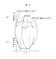
図4は、曲率半径Rs の円曲線上にある自車とRf 上にある先行車の関係を示している。自車からみて先行車が自車線上にあるか、隣接車線上にあるかは本来は自車と先行車の曲率半径の差ΔRで判断できる。
【0032】
演算の方法は以下の通りである。
【0033】
1.ミリ波レーダを用いて、距離TR と方位角度α、内蔵ジャイロセンサ6で自車角速度ωs 及び自車速度vs を計測する。
【0034】
2.横変位TC ,縦変位TD 及び自車曲率半径Rs を次式で計算する。
【0035】
TC=TRsinα,TD=TRcosα,Rs=vs/ωs
3.図4に示すように先行車の回転半径Rf は、次式が成立する。
【0036】
【0037】
【数2】
今、車線幅としてLyを仮定すると、
【0039】
【数3】
のとき自車線と判断する。Lyの値は、自車が車線中央を走っているとは限らないので、自車に対して左右対称の半車線幅とは限らない。その設定方法については後述の実施例で開示される。
【0041】
次に、図5および図6を使用して先行車の曲率半径Rfについての補正について説明する。現在、カーブ中の先行車の位置をジャイロセンサで測定した角速度をもとに補正し、先行車の車線位置を推定している。自車の角速度を用いるこの補正法では、先行車が現在の自車と同一の位置の回転中心から引いた円周上にあるとして計算されている。
【0042】
しかしながら、実際の道路は直線とカーブのみで構成されるのではなく、その間を徐々にRを変えながらつないで行く「緩和曲線」区間がかならず存在する。
したがって角速度が十分精度よく測定できたとしても、正しい測定ができるのは、先行車,自車とも直線にいるか円曲線内にあるときのみである。したがって、この緩和曲線の存在を検知してR補正することが重要になる。
【0043】
図5は、直線区間61につらなる緩和区間62,一定R区間63,緩和区間64,該緩和区間64につらなる直線区間65を示す。すなわち、緩和区間62ではRが徐々に小さくなり(角速度が増大)し、一定R区間(円曲線区間)63で一定R(角速度一定)となり、逆緩和区間64に入って徐々にRが増大していき(角速度減少)直線区間に復帰する。(直線ではR=∞)したがって、もし自車と先行車が同一の車線中央を走っていたとしても、自車が緩和区間62のときは、先行車はこれより小さいRを走行し、逆に64にいるときは先行車のRは自車の検出Rより大きくなっている。
【0044】
図6(a)(b)は、このようなカーブに入ってからの検出された角速度ωR の変化、及び曲率半径Rの変化とこのRの補正方向を示す。図に示すように緩和区間62でRを小さく補正して(R−ΔR)とし、一定R区間63でRのままとし、緩和区間63でRを大きく補正して (R+ΔR) として先行車の車線推定に反映させる。
【0045】
いま、先行車に相対速度のない状態で追従走行しているとする。このときRの補正を行うためには、
1.先行車との距離d,方位角度θ及びその変化Δθ
2.時々刻々の角速度ωRとその変化ΔωR
3.ステアリングの舵角φとその変化速度δφ
のセンサ情報を用いてなされる。
【0046】
図7は、補正手順を示すフローチャートである。まず、ステップ701において時刻tでの先行車との距離d(t),先行車方位角度θ(t),角速度ωR(t),ステアリング舵角φ(t)を検知し記憶する。次にステップ702において過去の時刻歴t−1,t−2,…を用いて微分フィルタ処理を行い、θ(t),ωR(t),φ(t)の変化Δθ(t),ΔωR(t),δφ(t)を求める。ステップ703において、Δθ(t)とδφ(t)の絶対値|Δθ(t)|と|δφ(t)|を判定する。共に大きく変化した場合、車線変更と判断され、補正処理の対象から外す(ステップ704)。一方、そのように判断されない場合は、補正処理の対象とする。ステップ705において、ΔωR(t)の正負を判断する。ΔωR>0の場合、自車は緩和区間62にあると判定され、R→(R−ΔR)と小さく補正される。(ステップ706),ΔωR<0の場合逆緩和区間64にあると判定され、R→(R+ΔR)と大きく補正される。(ステップ707),ΔωR=0の場合、円曲線区間61にあると判定され、R補正は実施されない(ステップ708)。
【0047】
ところで、ミリ波レーダをキーセンサとして警報及びACCシステムを構成する場合、走行中の先行車などの移動物対象については比較的問題が少ない。しかしながら、前方静止物に対する警報もしくはACC減速制御を行うのはきわめて難しい問題をはらんでいる。なぜならば、ミリ波レーダは物標との距離や相対速度及び角度を正確に測定することはできても、それが何であるか認識することはできない。例えば、前方にカーブがある場合、前方進行方向上に静止物を捉えたとしても、それが自車線上の停止車両か路側や路上にある標識などであるか判断することは難しい。このように、ミリ波レーダのみで判断できない場合が往々にして存在する。
【0048】
そこで、図8は、静止物に対する警報判断を正確にするために、図1の実施例に別種のセンサであるCCDカメラを加えた場合の実施例である。先に示した実施例の構成と同一の構成には同一番号を付し、説明を繰り返さない。図は、ミリ波レーダ,ジャイロセンサ,ステアリングセンサおよびCCDカメラからの信号を使用して構成する車間距離警報システム70を示す。図において、CCDカメラ71は、通常はその写真画像から白線認識72に用いられ、ズーミング機能を有している。一方、ミリ波レーダは距離や相対速度及び角度から静止物検知を行っている。今、ミリ波が前方に静止物23を検知した場合、カメラは白線認識72を一時中断し、ミリ波が捉えた前方静止物をズーミングする。そして、静止物認識73を行い、停止車両など障害物であるか、走行路外の標識や高架橋などの非障害物であるかを判定する。この静止物認識に基づいて警報判断14がなされ、静止物に対する警報指示15を行い警報信号16をドライバディスプレイ17に送る。
【0049】
図9は、同様に、ミリ波レーダ,ジャイロセンサ,ステアリングセンサおよびCCDカメラからの信号を使用して構成するACCシステム75を示す。図8同様の静止物検知−認識を行い、静止物認識73信号に基づいて車両の加減速判断25(静止物に対しては減速判断)がなされる。
【0050】
図10は、静止物の一例として高架橋と停止車両との区別を行った場合である。ミリ波レーダは、かなり前方、数値的には100−150[m]手前で高架橋を検知する。この時点では、前方静止物は高架橋であるか停止車両であるか判別できない。もしも検知した静止物が停止車両であった場合には、時速100km以上での高速走行においては、減速には時間がかかるのでこの時点で警報することが必要になる。そこで、カメラを用いた画像処理により高架橋であるか停止車両などの路上障害物であるか判断させる。画像処理で行うのは、パターンマッチングにより物標を識別することであり検知精度は要求されない。識別の結果、高架橋と判断された場合には、警報出力はしない。このように、ミリ波による物標検知とカメラ画像処理による物標識別を組合わせることで、警報の精度を向上させることができる。
【0051】
ところで、前方静止物が何であるか分かり、それが車線上にある停止車両など障害物であったとしても、警報を出すか否かの判断材料としては、完全ではない。例えば、前方に分岐路がありその片側に停止車両がある場合などは、その車両がどちらのコースを選択するかわからないと警報を出すべきかどうか正確な判断はできない。そこで、図11は、ミリ波レーダ,ジャイロセンサ,ステアリングセンサ,CCDカメラに加えナビゲーションシステムからの信号を使用して構成する車間距離警報システム76を示している。図において、ナビゲーションシステム77を使用して経路判断78を行う。ナビゲーションシステム以外のセンサにより静止物検知,静止物認識がなされ、停止車両などの警報対象物と判定されたとする。このとき、ナビゲーションシステム77の経路判断機能78によりその警報対象物が将来の走行車線上にあるか判断する。そして、走行車線上にあると判断された場合にのみ警報指示15を行う。これによって警報指示15の精度が向上する。
【0052】
図12は、同様に、ミリ波レーダ,ジャイロセンサ,ステアリングセンサ,
CCDカメラおよびナビゲーションシステムからの信号を使用して構成するACCシステム75を示す。図において、経路判断78による信号に基づいて加減速判断25がなされる。これによって、車間距離制御が精度高く行われることになる。
【0053】
前述した、図8〜図11の実施例においては、ミリ波レーダに加えてカメラ及びナビゲーションシステムを付加することで、静止物に対する警報もしくは制御を高精度化することを実現した。以下は、図1,図2のミリ波レーダ及びサブセンサとしてジャイロセンサ,ステアリングセンサのみを用いたシステムを前提とする。この場合、状況は限定されるとしても以下の問題を解決することにより、高精度の警報もしくは制御を実現できる。
【0054】
1.自車前方から始まるカーブを予測できないか?
2.自車は自車線の中央または端のどこを走行しているか推定できないか?
3.移動物の関係から自車線上に静止障害物があるか判定できないか?
以下、図面に基づいて説明する。
【0055】
図13(a)(b)は、複数の走行車線を有する道路において、自車の前方を走行する車両が横方向に移動していく2つの場合を示している。図13(a)は、自車がカーブ手前にあり前方車がカーブ路に差し掛かった場合、図13(b)は先行車が車線変更を行った場合である。図13(a)は、先行車は引き続き警報もしくは追従対象であり、図13(b)においては先行車は対象から外れることになる。両方とも自車から見ると先行車が横方向に移動していくように見えるが、他の車両の動きと比較して区別することができる。すなわち、前方車1および前方車2と先行車が同一横方向の動きをするか検知し、同一横方向の動きをしたときにカーブ、異なる動きをしたときに車線変更と判定する。
【0056】
図14は、図13(a)及び図13(b)を識別する手順を示すフローチャートである。
【0057】
まずステップ1401は時刻tでの先行車1との車間距離,方位角度、及び自車速度と相対速度から先行車速度、(d1(t),θ1(t),Vf1(t))を検知する。同様に、自車線以外の前方車2,3についても
(d2(t),θ2(t),Vf2(t)),(d3(t),θ3(t),Vf3(t))、を検知する。(ここでは検出する前方車を2台としたがもっと検知できている場合には検出台数を増やしても構わない。)
次に、ステップ1402において、過去の時刻歴t−1,t−2,…のデータを用いて微分フィルタ処理を行い、θ1(t),θ2(t),θ3(t)の変化Δθ1(t),Δθ2(t),Δθ3(t)を求める。ステップ1403では、(Δθ1(t)/Vf1(t)),(Δθ2(t)/Vf2(t)),(Δθ3(t)/Vf3(t))を求める。これは各車両が距離あたり変化する角度に相当し各車両の車速に依存しない量である。これを用いて、ステップ1404では、先行車と前方車1,2の移動量ΔM12=|(Δθ1/Vf1)−(Δθ2/Vf2)|,ΔM13=|(Δθ1/Vf1)−(Δθ3/Vf3)|を求め判定する。ΔM12ともΔM13の値が一定値以下であれば、カーブによる移動であると判定する(ステップ1405)。一方、ある値より大きい場合、車線変更が生じたと判定する(ステップ1406)。
【0058】
ここでは3車線の中央を自車及び先行車が走行し、左右車線に1台ずつ走行している例を示したが、2車線以上で先行車以外の前方車を捉えていれば同様の推定ができる。ただし、捕捉車両が多いほど推定精度は向上する。特に前方車が車線変更を行った場合など仮定が異なってくるが、捕捉対象車両を増やすことによりこうした誤推定を回避できる。
【0059】
ところで、図4や図13(a),(b)などでは、自車線推定にあたっては自車が車線中央を走っていると仮定して先行車の車線位置を判断している。例えば、図13(a)に示すように、先行車や前方車が車線中央を走っており、各車両の横方向距離が車線幅Lyにほぼ等しい場合などは問題がない。しかしながら、図13(b)のように自車,先行車,前方車が車線の片端に偏って走行している場合などはどちらが先行車かわからないことになる。この場合も含め、自車の白線に対する走行位置を推定し、それに応じて自車線の範囲を左右いずれかにオフセットさせて先行車判断に反映させることが重要である。
【0060】
図15は、この自車位置推定ならびに推定結果に基づき自車線位置を左右いずれかの方向にオフセットさせる方法に関するフローチャートである。まずステップ1601において先行車として認識している1台(図13(b)のように判断できない場合には方位角度の小さい側を先行車とする)以外の、左右前方車の横方向距離YL(t),YR(t)を求める。ステップ1602において、過去一定回数サンプルしたYL(t),YR(t)の移動平均値<YL(t)>,<YR(t)>を求める。ステップ1603において、得られた<YL(t)>,<YR(t)>に対して、
Ly+ΔLy<{(<YL(t)>+<YR(t)>)/2>}<Ly−Δly
(ここで、Ly:1車線幅,Δly:1車線幅より小さい値。)
であるかどうか判定する。条件が満たされない場合は、信頼性が低いデータであるとして採用されない。
【0061】
条件が満たされた場合、ステップ1604にうつり、次式にしたがい判定する。
【0062】
・{<YL(t)>−Ly}>ΔLyかつ{<YR(t)>−Ly}<ΔLy、のとき右側寄り
・{<YL(t)>−Ly}<ΔLyかつ{<YR(t)>−Ly}>ΔLy、のとき左側寄り
・{<YL(t)>−Ly}<ΔLyかつ{<YR(t)>−Ly}<ΔLy、のとき中央
ステップ1605ではその結果に応じて、自車線判定の範囲を右側もしくは左側にオフセットさせるかそのまま維持とするか判断する。
【0063】
以上は3車線の中央を走行している場合であるが、2車線あるいは対面道路であっても同様のことはできる。この場合は片側のみの前方車もしくは対面車との横距離をレファレンスに用いるが、サンプル数を増やすことにより信頼性を向上できる。なお、この方法では、ミリ波レーダの取付上の問題から車両の左右いずれかにオフセットさせて装着しなければならない場合においても自動推定して補正することが可能である。
【0064】
次に、先行車が横に移動し、その先に静止物が現われた場合について説明する。図16(a)(b)は、先行車が横に移動して、その先に静止物が現われた場合を示す。基本的には、図16(a)は警報を出すべきであり、図16(b)のケースでは出すべきでない。しかしながら、前方のコースが予測できないために、両者の区別がつかない。そこで、図17では、先行車の横移動の速度及びそのパターンに着目し、両者の区別を図る方法を示したものである。図のように、先行車の横方向移動速度を時間との関係で示すと、カーブの場合は、なだらかな変化となって検知されるが、車線変更の場合はステアリングの舵角が大きいために最初大きく、車線変更終了後はステアリングを戻すため横方向速度はなくなるような山形状の変化として検知される。自車は先行車の動きを検知しつつ静止物に接近していくが、自車の車速及び車間距離に応じて時間T1,T2,T3の位置と警報判断を行うタイミングが異なる。T2,T3の場合、判定はたやすく、先行車移動速度の変極点Pを検知することにより容易に両者を判別できる。一方、
T1の時点ではあるしきい値をもとに両者を判別する必要がある。このしきい値は自車速度,先行車速度,先行車方位角度,自車角速度、及び車間距離に応じて随時変更されるものである。
【0065】
図18は、対向車より遠距離にある静止物または静止物を対向車が横切る場合を示す。このような場合を検知したときは、自車線上にある静止物とはみなさず、警報は鳴らさない。方法としては、最初に捉えた静止物の方位角度付近の方位角度において対向車を捉え、その車間距離が静止物よりも近くであれば、その静止物は車線外の路側物であるとみなし警報対象にはしない。この場合、その判断は静止物と対向車を捉えた時間差をもとに自車の移動分を補正して判定されている。
【0066】
以上のように、本発明は、
・先行車位置の正しい推定式を提供し、それを用いた装置を提案した。
【0067】
・カーブ入口:角度速発生初期(増加方向)とカーブ出口:角速度発生後期(減少方向)で補正量を変更することとした。
【0068】
・複数先行車の検知位置をもとに、白線位置を推定することとした。また、前方車の横方向の移動量を検知して前方のカーブ,分岐を判断することにした。
【0069】
・ジャイロセンサおよびステアリングセンサの両方を用いて自車線の判断,先行車の位置補正を行うこととした。
【0070】
・先行車の動きから前方静止物の車線位置判定と静止物警報の有無を判定することとした。
【0071】
・対向車との位置関係から前方静止物の車線位置を判定することとした。
【0072】
・前方に検知した静止物が高架橋などの路上物であるかの認識を行い、その場合は警報しないこととした。
【0073】
・走行車線上に停止車両を捉えたとき、自車の走行経路であるかを判定し、経路であるときは警報することとした。
【0074】
・通信ネットワーク機能及び判断・制御機能を内蔵した一体型のミリ波レーダ装置を使用することを提案した。
【0075】
【発明の効果】
以上のように本発明によれば、
・ミリ波レーダを用いて自車線前方の先行車(停止車両を含む)を検知して、先行車との距離が目標値になるように制御し、あるいは、先行車と接近し過ぎた場合に警報音を発生する衝突警報を発することができる。
【0076】
・また、停止している先行車と路側にある標識や高架橋などの静止物を区別し、自車線前方にある停止車両に対してのみ警報あるいは制御(減速)を行うことができる。
【0077】
・レーダが捉えた先行車の動きやその他のセンサ情報をもとに、カーブ路などでも正確な自車線推定、及び位置補正が必要な場合には正確な補正ができる。
【0078】
・車両側からの各種データを受信し、ミリ波レーダにより得た検知情報と合わせて先行車の車線位置推定を行い、警報または制御指令情報を車両側に送信できる。
【図面の簡単な説明】
【図1】車間距離警報システムの概略構成図。
【図2】ACCシステムの概略構成図。
【図3】制御ブロック図。
【図4】計算方式図。
【図5】曲率半径説明図。
【図6】(a)(b)は曲率変化と補正の関係図。
【図7】補正手順のフローチャート図
【図8】車間距離警報システムの概略構成図。
【図9】ACCシステムの概略構成図。
【図10】高架橋と停止車両の識別図。
【図11】車間距離警報システムの概略構成図。
【図12】ACCシステムの概略構成図。
【図13】(a)(b)は先行車のカーブと車線変更の識別図。
【図14】識別方法のフローチャート。
【図15】自車線位置推定のフローチャート
【図16】(a)(b)は先行車および静止物認識図。移動速度図。
【図17】カーブと車線変更の横方向移動図。
【図18】対向車および静止物認識図。
【符号の説明】
1…車間距離警報システム、2…自車、3…先行車、4…アンテナユニット、5…車間距離・対向速度・角度計測、6…ジャイロセンサ、7…ステアリングセンサ、8…角速度、9…舵角、10…車線判断、11…先行車判定、12…静止物判定、13…警報判定アルゴリズム、14…警報判断、15…警報指示、21…ACCシステム、22…先行車検知、23…静止物検知、24…車間距離制御アルゴリズム、25…加減速判断、26…車速信号・ブレーキ信号、28…車間距離制御、70…車間距離警報システム、71…CCDカメラ、72…白線認識、77…ナビゲーションシステム、78…経路判断。[0001]
BACKGROUND OF THE INVENTION
The present invention relates to an estimation apparatus using a radar or the like for detecting a dangerous object for an automobile. In particular, the present invention relates to an apparatus for identifying various non-hazardous and genuine dangerous materials commonly encountered in typical automobile driving environments.
[0002]
[Prior art]
Many attempts have been made in the field of vehicular radar systems to measure the distance of dangerous goods and their relative velocities. Japanese Patent Laid-Open No. 6-282798 discloses a target capturing means for obtaining a relative position of a target with respect to a traveling body by searching the periphery of the traveling body and capturing a target, and a circular trajectory of the traveling body in a turning motion of the traveling body. Based on the circular orbit estimating means to be estimated, the relative position of the target obtained by the target capturing means, and the circular orbit of the operating body (4) estimated by the circular orbit estimating means, the target is on the circular orbit. The target searching device is characterized by having control means for determining whether or not the vehicle is located on the route of the operation body and identifying the target located on the route of the operating body. Japanese Laid-Open Patent Publication No. 8-83400 discloses a danger to a vehicle in a road surface vehicle radar system that can detect the presence of one or more objects close to the vehicle traveling in the first lane. In a method for identifying an object as an object from a non-hazardous object to a vehicle, the vehicle has a beam width sufficient to illuminate an object in a second lane adjacent to the first lane, and substantially the direction of movement of the vehicle. Generating a radar beam that is at least partially generated along a first axis that is perpendicular to the direction, receiving a reflected signal from an illuminated object, and a direction of travel of the vehicle based on the reflected signal Estimating the speed of the illuminated object with respect to the vehicle speed in the direction of the second axis (x) substantially parallel to and measuring the speed of the vehicle using at least one speed sensor If the sum of the step and the measured vehicle speed and the estimated parallel object speed is greater than a predetermined threshold, the irradiated object is determined to be dangerous, and the measured vehicle speed is estimated. And determining that the irradiated object is not dangerous if the sum of the parallel object velocities is less than a predetermined threshold.
[0003]
[Problems to be solved by the invention]
Detects preceding vehicles (including stopped vehicles and objects; hereinafter referred to as targets) in front of the host lane and controls the distance from the preceding vehicle to the target value (ACC: Adaptive Cruise Control) or preceding Consider the sensing requirements necessary for a system that generates a warning sound when a vehicle or target is too close. The following three steps are considered necessary.
[0004]
First stage: Can you see the detection capability, that is, the target in front (vehicle or roadside object)?
i) Ability to detect distance (particularly maximum), relative speed and angle with the target
ii) Accuracy of lane judgment of own lane / other lane
Second stage: Do you know the discrimination ability, ie what the forward target is?
In particular, is it possible to identify what is the front stationary object on the front lane (ex: distinguishing stationary vehicles, roadside objects such as corner poles and signs, and roadside objects such as viaducts).
[0005]
Stage 3: Decision making, ie in which direction is the driver going? Is the front obstacle included in the future driving locus based on the driver's intention (if it is not included, it is not necessary to generate an alarm).
In view of this point, the present invention improves the accuracy of lane determination of the own lane / other lane, detects the preceding vehicle or target ahead of the own lane, and controls the distance from the preceding vehicle to the target value. Alternatively, an object of the present invention is to provide a lane position estimating device for a preceding vehicle or a target that can accurately issue a collision warning for preventing a target from colliding. In addition, the present invention provides a lane position estimation device for a forward stationary object that can accurately recognize whether a forward stationary object on the forward lane is a dangerous object or on the own lane. Objective.
[0006]
In addition, the present invention distinguishes between a preceding vehicle that is stopped and a stationary object such as a roadside sign or a viaduct so that a warning or control (deceleration) can be performed on a stopped vehicle in front of the vehicle. The purpose is to do.
[0007]
[Means for Solving the Problems]
For this reason, the present invention
・ Provide an estimation algorithm that can accurately correct the vehicle's own lane, even on curved roads, if necessary, based on the movement of the preceding vehicle captured by the radar and other sensor information.
・ Communication network function and judgment / control function that receives various data from the vehicle side, estimates the lane position of the preceding vehicle together with the detection information obtained by the millimeter wave radar, and transmits alarm or control command information to the vehicle side An integrated millimeter-wave radar device with a built-in type is provided.
[0008]
Specifically, the present invention provides the following apparatus.
[0009]
The present invention is based on the distance and azimuth angle between the own vehicle input from the radar and the preceding vehicle or the target, the own vehicle angular velocity input from the sensor, and the curvature of the preceding vehicle or the target based on the own vehicle speed. If the absolute value of the difference in curvature radius is smaller than one half of the lane width, it is determined that the preceding vehicle is in the lane of the own vehicle, and the own vehicle is determined based on the determination result. It is the control apparatus or system of the motor vehicle which controls driving | running | working of this or generates an alarm according to the said judgment result.
[0010]
Preferably, the control device sets the distance to T. R , The azimuth angle is α, the vehicle angular velocity is ω S The vehicle speed is V S R = V S / Ω S , T C = T R sin α, T D = T R cos When α is
[Expression 1]
[0011]
Preferably, the curvature radius value is corrected to be small when the result of the differential filter processing of the vehicle angular velocity is positive, and the curvature radius value is increased when the result is negative. It is to be corrected to.
[0012]
Further, the present invention relates to the distance and azimuth between the own vehicle inputted from the radar and the preceding vehicle or the target, the own vehicle angular velocity inputted from the sensor and the own vehicle speed, and the own vehicle and the preceding vehicle or the target. A vehicle control device or system that obtains a parameter indicating a positional relationship and determines whether an alarm is generated based on the parameter,
The correction amount of the parameter is changed at the curve entrance and exit.
[0022]
DETAILED DESCRIPTION OF THE INVENTION
Embodiments of the present invention will be described below with reference to the drawings.
[0023]
FIG. 1 shows an inter-vehicle
[0024]
FIG. 2 shows an
[0025]
1 and 2, that is, the alarm system and the ACC system do not necessarily exist only as separate systems, but may have a system configuration having both functions combined.
[0026]
FIG. 3 is a block diagram showing a hardware configuration for realizing the system embodiment shown in FIGS. The configuration shown in the figure includes an integrated millimeter
[0027]
The integrated millimeter
[0028]
The vehicle
[0029]
In these system configurations, the vehicle-
[0030]
Next, a description will be given of a method for determining the lane especially on the curve and derivation of an arithmetic expression in the built-in software 47.
[0031]
FIG. 4 shows the radius of curvature RsR and your car on the circle curvefIt shows the relationship of the preceding car above. Whether the preceding vehicle is on the own lane or the adjacent lane as viewed from the own vehicle can be originally determined by the difference ΔR between the curvature radii of the own vehicle and the preceding vehicle.
[0032]
The calculation method is as follows.
[0033]
1. Using a millimeter wave radar, the distance TRAnd azimuth angle α, the vehicle's angular velocity ω with the built-in
[0034]
2. Lateral displacement TC, Longitudinal displacement TDAnd radius of curvature RsIs calculated by the following equation.
[0035]
TC= TRsinα, TD= TRcosα, Rs= Vs/ Ωs
3. As shown in FIG. 4, the turning radius R of the preceding vehiclefThe following equation holds.
[0036]
[0037]
[Expression 2]
Assuming that Ly is the lane width,
[0039]
[Equation 3]
When it is, it is judged as the own lane. Since the value of Ly does not necessarily mean that the vehicle is running in the center of the lane, it is not necessarily a half-lane width that is symmetrical with respect to the vehicle. The setting method will be disclosed in an embodiment described later.
[0041]
Next, correction for the curvature radius Rf of the preceding vehicle will be described with reference to FIGS. 5 and 6. Currently, the position of the preceding vehicle in the curve is corrected based on the angular velocity measured by the gyro sensor, and the lane position of the preceding vehicle is estimated. In this correction method using the angular velocity of the own vehicle, the preceding vehicle is calculated as being on the circumference drawn from the rotation center at the same position as the current own vehicle.
[0042]
However, an actual road is not composed only of straight lines and curves, but there is always a “relaxation curve” section that connects the roads while gradually changing R.
Therefore, even if the angular velocity can be measured with sufficient accuracy, the correct measurement can be performed only when both the preceding vehicle and the own vehicle are in a straight line or in a circular curve. Therefore, it is important to detect the presence of the relaxation curve and correct the R.
[0043]
FIG. 5 shows a
[0044]
6A and 6B show the detected angular velocity ω after entering such a curve.R, The change of the radius of curvature R, and the correction direction of R. As shown in the figure, R is corrected to be small (R−ΔR) in the
[0045]
It is assumed that the vehicle is following the vehicle without relative speed. At this time, in order to correct R,
1. Distance d with preceding vehicle, azimuth angle θ and change Δθ
2. Angular velocity ω every momentRAnd its change ΔωR
3. Steering angle φ and its speed of change δφ
This is done using the sensor information.
[0046]
FIG. 7 is a flowchart showing the correction procedure. First, in step 701, the distance d (t) with the preceding vehicle at time t, the preceding vehicle azimuth angle θ (t), and the angular velocity ω.R(t), the steering angle φ (t) is detected and stored. Next, in step 702, differential filtering is performed using the past time histories t-1, t-2,..., Θ (t), ωRChanges in (t), φ (t) Δθ (t), ΔωR(t) and δφ (t) are obtained. In step 703, the absolute values | Δθ (t) | and | δφ (t) | of Δθ (t) and δφ (t) are determined. If both have changed significantly, it is determined that the lane has been changed, and is excluded from correction processing targets (step 704). On the other hand, if it is not determined as such, it is the target of correction processing. In step 705, ΔωRJudge the sign of (t). ΔωRIf> 0, the vehicle is determined to be in the
[0047]
By the way, when an alarm and ACC system is configured using a millimeter wave radar as a key sensor, there are relatively few problems with respect to moving objects such as a preceding vehicle that is running. However, it is extremely difficult to perform an alarm or ACC deceleration control for a stationary stationary object. This is because even though the millimeter wave radar can accurately measure the distance, relative speed and angle with the target, it cannot recognize what it is. For example, when there is a curve ahead, even if a stationary object is captured in the forward traveling direction, it is difficult to determine whether it is a stopped vehicle on the own lane or a sign on the roadside or on the road. As described above, there is often a case where the determination cannot be made only by the millimeter wave radar.
[0048]
FIG. 8 shows an embodiment in which a CCD camera, which is another type of sensor, is added to the embodiment of FIG. The same reference numerals are given to the same components as those of the above-described embodiment, and the description will not be repeated. The figure shows an inter-vehicle
[0049]
FIG. 9 similarly shows an
[0050]
FIG. 10 shows a case where a viaduct and a stopped vehicle are distinguished as an example of a stationary object. The millimeter wave radar detects a viaduct considerably ahead, numerically 100-150 [m]. At this time, it cannot be determined whether the front stationary object is a viaduct or a stopped vehicle. If the detected stationary object is a stopped vehicle, it is necessary to warn at this point because it takes time to decelerate at high speed traveling at 100 km / h or higher. Therefore, it is determined whether the vehicle is a viaduct or a road obstacle such as a stopped vehicle by image processing using a camera. What is performed in image processing is to identify a target by pattern matching, and detection accuracy is not required. As a result of identification, if it is determined that the bridge is a viaduct, no warning is output. Thus, the accuracy of the alarm can be improved by combining the target detection by millimeter wave and the target labeling by camera image processing.
[0051]
By the way, even if it is understood what the front stationary object is and is an obstacle such as a stopped vehicle on the lane, it is not perfect as a material for determining whether or not to issue an alarm. For example, when there is a branch road ahead and there is a stopped vehicle on one side, it is impossible to accurately determine whether or not an alarm should be issued unless the vehicle selects which course. FIG. 11 shows an inter-vehicle
[0052]
Similarly, FIG. 12 shows a millimeter wave radar, a gyro sensor, a steering sensor,
An
[0053]
In the embodiments shown in FIGS. 8 to 11 described above, it is possible to increase the accuracy of warning or control for a stationary object by adding a camera and a navigation system in addition to the millimeter wave radar. The following is based on the system using only the millimeter wave radar and the gyro sensor and the steering sensor as sub sensors in FIGS. In this case, even if the situation is limited, it is possible to realize a highly accurate alarm or control by solving the following problems.
[0054]
1. Can you predict a curve that starts from the front of your vehicle?
2. Can't you estimate where your car is driving in the middle or end of your lane?
3. Is it possible to determine if there is a stationary obstacle on the lane due to the moving object?
Hereinafter, description will be given based on the drawings.
[0055]
FIGS. 13A and 13B show two cases in which a vehicle traveling in front of the host vehicle moves in the lateral direction on a road having a plurality of traveling lanes. FIG. 13A shows the case where the host vehicle is in front of the curve and the preceding vehicle approaches the curve road, and FIG. 13B shows the case where the preceding vehicle has changed lanes. In FIG. 13A, the preceding vehicle continues to be an alarm or follow-up target, and in FIG. 13B, the preceding vehicle is excluded from the target. In both cases, when viewed from the own vehicle, the preceding vehicle appears to move laterally, but it can be distinguished from the movement of other vehicles. That is, it is detected whether the
[0056]
FIG. 14 is a flowchart showing a procedure for identifying FIGS. 13 (a) and 13 (b).
[0057]
First, in step 1401, the preceding vehicle speed (d1 (t), θ1 (t), Vf1 (t)) is detected from the inter-vehicle distance from the preceding
(d2 (t), θ2 (t), Vf2 (t)), (d3 (t), θ3 (t), Vf3 (t)) are detected. (Here, the number of front vehicles to be detected is two. However, if more vehicles can be detected, the number of detected vehicles may be increased.)
Next, in step 1402, differential filter processing is performed using data of past time histories t-1, t-2,..., And changes Δθ1 (t) of θ1 (t), θ2 (t), θ3 (t) are performed. ), Δθ2 (t), Δθ3 (t). In step 1403, (Δθ1 (t) / Vf1 (t)), (Δθ2 (t) / Vf2 (t)), and (Δθ3 (t) / Vf3 (t)) are obtained. This corresponds to an angle at which each vehicle changes per distance, and is an amount that does not depend on the vehicle speed of each vehicle. Using this, in step 1404, the movement amount ΔM12 = | (Δθ1 / Vf1) − (Δθ2 / Vf2) |, ΔM13 = | (Δθ1 / Vf1) − (Δθ3 / Vf3) between the preceding vehicle and the preceding
[0058]
Here, an example is shown in which the vehicle and the preceding vehicle are traveling in the center of the three lanes, and one vehicle is traveling in each of the left and right lanes. Can do. However, the estimation accuracy improves as the number of captured vehicles increases. Although the assumptions are different especially when the vehicle ahead changes lanes, such erroneous estimation can be avoided by increasing the number of vehicles to be captured.
[0059]
By the way, in FIG.4, FIG.13 (a), (b), etc., when estimating own lane, the lane position of a preceding vehicle is judged on the assumption that the own vehicle is running in the center of the lane. For example, as shown in FIG. 13A, there is no problem when a preceding vehicle or a preceding vehicle runs in the center of the lane and the lateral distance of each vehicle is substantially equal to the lane width Ly. However, as shown in FIG. 13B, when the host vehicle, the preceding vehicle, and the preceding vehicle are traveling with bias toward one end of the lane, it is not known which is the preceding vehicle. Including this case, it is important to estimate the traveling position of the own vehicle with respect to the white line and offset the range of the own lane to the left or right accordingly and reflect it in the preceding vehicle determination.
[0060]
FIG. 15 is a flowchart regarding a method of offsetting the own lane position in either the left or right direction based on the own vehicle position estimation and the estimation result. First, in step 1601, the lateral distance YL of the left and right front vehicles other than the one that is recognized as the preceding vehicle (if the vehicle cannot be determined as shown in FIG. 13B, the smaller azimuth angle is the preceding vehicle). t) and YR (t) are obtained. In step 1602, moving average values <YL (t)> and <YR (t)> of YL (t) and YR (t) sampled a certain number of times in the past are obtained. In step 1603, for the obtained <YL (t)>, <YR (t)>,
Ly + ΔLy <{(<YL (t)> + <YR (t)>) / 2>} <Ly−Δly
(Here, Ly: 1 lane width, Δly: 1 lane width smaller value.)
It is determined whether or not. If the condition is not satisfied, the data is not adopted because it has low reliability.
[0061]
If the condition is satisfied, the process proceeds to step 1604 and a determination is made according to the following equation.
[0062]
・ When {<YL (t)>-Ly}> ΔLy and {<YR (t)>-Ly} <ΔLy, it is closer to the right side
・ {<YL (t)> − Ly} <ΔLy and {<YR (t)> − Ly}> ΔLy
・ {<YL (t)> − Ly} <ΔLy and {<YR (t)> − Ly} <ΔLy, the center
In step 1605, it is determined according to the result whether the range of the own lane determination is offset to the right side or the left side or is maintained as it is.
[0063]
The above is a case where the vehicle is traveling in the center of three lanes, but the same can be done for two lanes or facing roads. In this case, the lateral distance from the front vehicle or the facing vehicle on only one side is used as a reference, but the reliability can be improved by increasing the number of samples. In this method, it is possible to automatically estimate and correct even when it is necessary to offset the vehicle to be mounted on either the left or right side of the vehicle due to a problem in mounting the millimeter wave radar.
[0064]
Next, a case where the preceding vehicle moves sideways and a stationary object appears ahead of it will be described. FIGS. 16A and 16B show a case where the preceding vehicle moves sideways and a stationary object appears ahead of it. Basically, FIG. 16 (a) should give an alarm and not in the case of FIG. 16 (b). However, since the course ahead cannot be predicted, the two cannot be distinguished. Therefore, FIG. 17 shows a method of distinguishing both by paying attention to the speed and pattern of the lateral movement of the preceding vehicle. As shown in the figure, when the lateral movement speed of the preceding vehicle is shown in relation to time, in the case of a curve, it is detected as a gentle change, but in the case of a lane change, the steering angle of the steering is large. First, it is detected as a change in mountain shape so that the lateral speed disappears because the steering is returned after the lane change is completed. The own vehicle approaches the stationary object while detecting the movement of the preceding vehicle, but the positions of the times T1, T2 and T3 and the timing for making the alarm judgment differ depending on the speed of the own vehicle and the inter-vehicle distance. In the case of T2 and T3, the determination is easy and both can be easily determined by detecting the inflection point P of the preceding vehicle moving speed. on the other hand,
At the time of T1, it is necessary to discriminate both based on a certain threshold value. This threshold value is changed at any time according to the own vehicle speed, the preceding vehicle speed, the preceding vehicle azimuth angle, the own vehicle angular velocity, and the inter-vehicle distance.
[0065]
FIG. 18 illustrates a case where the oncoming vehicle crosses a stationary object or a stationary object that is farther away than the oncoming vehicle. When such a case is detected, it is not regarded as a stationary object on its own lane, and an alarm is not sounded. As a method, if the oncoming vehicle is caught at an azimuth angle near the azimuth angle of the stationary object that was first captured, and the distance between the vehicles is closer than the stationary object, the stationary object is regarded as a roadside object outside the lane. Not targeted. In this case, the determination is made by correcting the movement of the own vehicle based on the time difference between the stationary object and the oncoming vehicle.
[0066]
As described above, the present invention
・ Provided a correct estimation formula for the position of the preceding vehicle and proposed a device using it.
[0067]
・ Curve entrance: The correction amount was changed at the initial stage of angular velocity generation (increase direction) and at the exit of the curve: late stage of angular velocity generation (decrease direction).
[0068]
-The white line position was estimated based on the detection positions of multiple preceding vehicles. In addition, we decided to determine the curve and branch ahead by detecting the amount of lateral movement of the vehicle ahead.
[0069]
-Both the gyro sensor and the steering sensor are used to determine the own lane and correct the position of the preceding vehicle.
[0070]
・ From the movement of the preceding vehicle, it was decided to determine the lane position of the stationary stationary object and whether there was a stationary object warning.
[0071]
-The lane position of the stationary stationary object is determined from the positional relationship with the oncoming vehicle.
[0072]
・ Recognized whether the stationary object detected in front is an object on the road such as a viaduct, and in that case, the alarm was not issued.
[0073]
-When a stopped vehicle is caught on the driving lane, it is determined whether it is the driving route of the vehicle, and if it is a route, an alarm is given.
[0074]
・ It was proposed to use an integrated millimeter-wave radar device with built-in communication network functions and judgment / control functions.
[0075]
【The invention's effect】
As described above, according to the present invention,
・ Use millimeter wave radar to detect preceding vehicles (including stopped vehicles) ahead of the lane and control the distance to the target vehicle to be the target value, or when the vehicle approaches too far A collision alarm that generates an alarm sound can be issued.
[0076]
In addition, it is possible to distinguish between a preceding vehicle that is stopped and a stationary object such as a sign or a viaduct on the roadside, and perform warning or control (deceleration) only for a stopped vehicle in front of the own lane.
[0077]
-Based on the movement of the preceding vehicle captured by the radar and other sensor information, it is possible to accurately correct the own lane estimation and position correction even on curved roads.
[0078]
-It can receive various data from the vehicle side, estimate the lane position of the preceding vehicle together with the detection information obtained by the millimeter wave radar, and transmit alarm or control command information to the vehicle side.
[Brief description of the drawings]
FIG. 1 is a schematic configuration diagram of an inter-vehicle distance warning system.
FIG. 2 is a schematic configuration diagram of an ACC system.
FIG. 3 is a control block diagram.
FIG. 4 is a calculation method diagram.
FIG. 5 is an explanatory diagram of a radius of curvature.
FIGS. 6A and 6B are diagrams showing the relationship between curvature change and correction.
FIG. 7 is a flowchart of a correction procedure.
FIG. 8 is a schematic configuration diagram of an inter-vehicle distance warning system.
FIG. 9 is a schematic configuration diagram of an ACC system.
FIG. 10 is an identification diagram of a viaduct and a stopped vehicle.
FIG. 11 is a schematic configuration diagram of an inter-vehicle distance warning system.
FIG. 12 is a schematic configuration diagram of an ACC system.
FIGS. 13A and 13B are identification diagrams of a curve and a lane change of a preceding vehicle.
FIG. 14 is a flowchart of an identification method.
FIG. 15 is a flowchart of self-lane position estimation.
16 (a) and 16 (b) are front and stationary object recognition diagrams. Movement speed diagram.
FIG. 17 is a lateral movement diagram of curve and lane change.
FIG. 18 is an oncoming vehicle and stationary object recognition diagram.
[Explanation of symbols]
DESCRIPTION OF
Claims (10)
自車角速度及び自車速度を検出するセンサと、A sensor for detecting the vehicle angular speed and the vehicle speed;
前記レーダから入力した自車と先行車または物標との距離及び方位角度、並びに前記センサから入力した自車角速度及び前記自車速度に基づいて自車と先行車または物標との曲率半径の差を求め、車線幅の2分の1よりも前記曲率半径の差の絶対値が小さい場合は、先行車が自車の車線内に存在すると判断し、当該判断結果に基づいて自車の走行を制御する制御装置と、Based on the distance and azimuth angle between the vehicle input from the radar and the preceding vehicle or the target, and the vehicle angular velocity and the vehicle speed input from the sensor, the curvature radius between the vehicle and the preceding vehicle or the target is calculated. If the absolute value of the difference in radius of curvature is smaller than one half of the lane width, it is determined that the preceding vehicle is in the lane of the host vehicle, and the vehicle travels based on the determination result. A control device for controlling
を有する自動車の制御システム。Automobile control system having
自車角速度及び自車速度を検出するセンサと、A sensor for detecting the vehicle angular speed and the vehicle speed;
前記レーダから入力した自車と先行車または物標との距離及び方位角度、並びに前記センサから入力した自車角速度及び前記自車速度に基づいて自車と先行車または物標との曲率半径の差を求め、車線幅の2分の1よりも前記曲率半径の差の絶対値が小さい場合は、先行車が自車の車線内に存在すると判断し、当該判断結果に応じて警報を発生する制御装置と、Based on the distance and azimuth angle between the vehicle input from the radar and the preceding vehicle or the target, and the vehicle angular velocity and the vehicle speed input from the sensor, the curvature radius between the vehicle and the preceding vehicle or the target is calculated. If the absolute value of the difference in radius of curvature is smaller than half the lane width, it is determined that the preceding vehicle is in the lane of the host vehicle, and an alarm is generated according to the determination result. A control device;
を有する自動車の制御システム。Automobile control system having
前記制御装置は、前記距離をTThe control device sets the distance to T RR 、前記方位角度をα、前記自車角速度をω, The azimuth angle is α, the vehicle angular velocity is ω SS 、前記自車速度をVThe vehicle speed is V SS とし、R=VR = V SS /ω/ Ω SS ,T, T CC =T= T RR sinsin α,Tα, T DD =T= T RR coscos αとしたときに、When α is
前記制御装置は、前記自車角速度の微分フィルタ処理の結果が正である場合には前記曲率半径値が小さくなるように補正し、前記結果が負である場合には前記曲率半径値が大きくなるように補正する自動車の制御システム。The control device corrects the curvature radius value to be small when the result of the differential filter processing of the vehicle angular velocity is positive, and increases the curvature radius value when the result is negative. To correct the car control system.
自車角速度及び自車速度を検出するセンサと、A sensor for detecting the vehicle angular velocity and the vehicle speed;
前記レーダから入力した自車と先行車または物標との距離及び方位角度、並びに前記センサから入力した自車角速度及び前記自車速度に応じて自車と先行車または物標との位置関係を示すパラメータを求め、当該パラメータに基づいて警報の発生有無を決定する制御装置と、The positional relationship between the own vehicle and the preceding vehicle or the target according to the distance and azimuth angle between the own vehicle inputted from the radar and the preceding vehicle or the target, and the own vehicle angular speed and the own vehicle speed inputted from the sensor. A control device that determines a parameter to be indicated and determines whether an alarm is generated based on the parameter;
を有する自動車の制御システムであって、A vehicle control system comprising:
前記制御装置は、カーブ入口および出口で前記パラメータの補正量を変更する自動車の制御システム。The control device is an automobile control system that changes a correction amount of the parameter at an entrance and an exit of a curve.
前記制御装置は、前記距離をTThe control device sets the distance to T RR 、前記方位角度をα、前記自車角速度をω, The azimuth angle is α, the vehicle angular velocity is ω SS 、前記自車速度をVThe vehicle speed is V SS とし、R=VR = V SS /ω/ Ω SS ,T, T CC =T= T RR sinsin α,Tα, T DD =T= T RR coscos αとしたときに、When α is
前記自車角速度の微分フィルタ処理の結果が正である場合には前記曲率半径値が小さくなるように補正され、前記結果が負である場合には前記曲率半径値が大きくなるように補正される自動車の制御装置。When the result of the differential filter processing of the vehicle angular velocity is positive, the curvature radius value is corrected to be small, and when the result is negative, the curvature radius value is corrected to be large. Automotive control device.
カーブ入口および出口で前記パラメータの補正量を変更する自動車の制御装置。A control apparatus for an automobile that changes the correction amount of the parameter at a curve entrance and exit.
Priority Applications (7)
| Application Number | Priority Date | Filing Date | Title |
|---|---|---|---|
| JP18107099A JP3658519B2 (en) | 1999-06-28 | 1999-06-28 | Vehicle control system and vehicle control device |
| DE60030810T DE60030810T2 (en) | 1999-06-28 | 2000-06-28 | Control and warning procedures for motor vehicles |
| EP00113119A EP1065520B1 (en) | 1999-06-28 | 2000-06-28 | Vehicle control method and vehicle warning method |
| EP06017138A EP1720036A1 (en) | 1999-06-28 | 2000-06-28 | Vehicle control method and vehicle warning method |
| US09/605,052 US6311123B1 (en) | 1999-06-28 | 2000-06-28 | Vehicle control method and vehicle warning method |
| US09/944,201 US6684149B2 (en) | 1999-06-28 | 2001-09-04 | Vehicle control method and vehicle warning method |
| US09/986,364 US6567737B2 (en) | 1999-06-28 | 2001-11-08 | Vehicle control method and vehicle warning method |
Applications Claiming Priority (1)
| Application Number | Priority Date | Filing Date | Title |
|---|---|---|---|
| JP18107099A JP3658519B2 (en) | 1999-06-28 | 1999-06-28 | Vehicle control system and vehicle control device |
Publications (2)
| Publication Number | Publication Date |
|---|---|
| JP2001014597A JP2001014597A (en) | 2001-01-19 |
| JP3658519B2 true JP3658519B2 (en) | 2005-06-08 |
Family
ID=16094285
Family Applications (1)
| Application Number | Title | Priority Date | Filing Date |
|---|---|---|---|
| JP18107099A Expired - Fee Related JP3658519B2 (en) | 1999-06-28 | 1999-06-28 | Vehicle control system and vehicle control device |
Country Status (4)
| Country | Link |
|---|---|
| US (3) | US6311123B1 (en) |
| EP (2) | EP1065520B1 (en) |
| JP (1) | JP3658519B2 (en) |
| DE (1) | DE60030810T2 (en) |
Cited By (1)
| Publication number | Priority date | Publication date | Assignee | Title |
|---|---|---|---|---|
| US7765048B2 (en) | 2003-10-15 | 2010-07-27 | Nissan Motor Co., Ltd. | Deceleration control apparatus and method for automotive vehicle |
Families Citing this family (177)
| Publication number | Priority date | Publication date | Assignee | Title |
|---|---|---|---|---|
| US6580385B1 (en) * | 1999-05-26 | 2003-06-17 | Robert Bosch Gmbh | Object detection system |
| JP3658519B2 (en) * | 1999-06-28 | 2005-06-08 | 株式会社日立製作所 | Vehicle control system and vehicle control device |
| JP3529037B2 (en) * | 1999-08-02 | 2004-05-24 | 日産自動車株式会社 | Lane tracking device |
| KR100729986B1 (en) * | 1999-12-20 | 2007-06-20 | 아시스트 신꼬, 인코포레이티드 | Auto-carrying system |
| US7593838B2 (en) * | 2000-03-28 | 2009-09-22 | Robert Bosch Gmbh | Model-supported allocation of vehicles to traffic lanes |
| JP3427815B2 (en) * | 2000-03-30 | 2003-07-22 | 株式会社デンソー | Method and apparatus for selecting preceding vehicle, recording medium |
| DE10026032A1 (en) * | 2000-05-25 | 2001-11-29 | Bayerische Motoren Werke Ag | Device and method for determining distance and speed |
| DE10030258A1 (en) * | 2000-06-20 | 2002-01-03 | Daimler Chrysler Ag | Method for controlling the distance of a vehicle from a preceding vehicle and distance control system |
| NL1015517C2 (en) * | 2000-06-23 | 2001-12-28 | Tno | Scheme for conducting research on intelligent road vehicles. |
| JP3639191B2 (en) * | 2000-07-10 | 2005-04-20 | 株式会社デンソー | Object recognition method and apparatus, and recording medium |
| JP3681620B2 (en) * | 2000-07-26 | 2005-08-10 | 株式会社デンソー | Obstacle recognition device for vehicles |
| JP3872638B2 (en) * | 2000-08-29 | 2007-01-24 | 株式会社日立製作所 | Cruise control system and vehicle equipped with it |
| JP3671825B2 (en) * | 2000-09-22 | 2005-07-13 | 日産自動車株式会社 | Inter-vehicle distance estimation device |
| EP1349131B1 (en) * | 2000-11-24 | 2006-01-18 | Aisin Seiki Kabushiki Kaisha | Vehicle collision preventing apparatus |
| JP3800007B2 (en) * | 2001-01-09 | 2006-07-19 | 日産自動車株式会社 | Braking control device |
| JP3995890B2 (en) * | 2001-03-05 | 2007-10-24 | 株式会社村田製作所 | Radar |
| JP3646660B2 (en) * | 2001-03-26 | 2005-05-11 | 日産自動車株式会社 | Vehicle tracking control device |
| DE10128792B4 (en) * | 2001-05-08 | 2005-06-09 | Daimlerchrysler Ag | Collision protection for vehicles |
| GB0111979D0 (en) * | 2001-05-17 | 2001-07-04 | Lucas Industries Ltd | Sensing apparatus for vehicles |
| US7027615B2 (en) * | 2001-06-20 | 2006-04-11 | Hrl Laboratories, Llc | Vision-based highway overhead structure detection system |
| JP2003072416A (en) * | 2001-08-31 | 2003-03-12 | Denso Corp | Vehicular travel control device |
| US6944543B2 (en) * | 2001-09-21 | 2005-09-13 | Ford Global Technologies Llc | Integrated collision prediction and safety systems control for improved vehicle safety |
| US6859705B2 (en) * | 2001-09-21 | 2005-02-22 | Ford Global Technologies, Llc | Method for operating a pre-crash sensing system with object classifier in a vehicle having a countermeasure system |
| US6775605B2 (en) * | 2001-11-29 | 2004-08-10 | Ford Global Technologies, Llc | Remote sensing based pre-crash threat assessment system |
| DE10159658A1 (en) * | 2001-12-05 | 2003-06-26 | Daimler Chrysler Ag | System for automatically following a motor vehicle |
| JP4019736B2 (en) * | 2002-02-26 | 2007-12-12 | トヨタ自動車株式会社 | Obstacle detection device for vehicle |
| US6643588B1 (en) * | 2002-04-11 | 2003-11-04 | Visteon Global Technologies, Inc. | Geometric based path prediction method using moving and stop objects |
| JP3860061B2 (en) * | 2002-04-16 | 2006-12-20 | 富士重工業株式会社 | Outside-of-vehicle monitoring device and travel control device equipped with this out-of-vehicle monitoring device |
| US6753804B2 (en) * | 2002-05-21 | 2004-06-22 | Visteon Global Technologies, Inc. | Target vehicle identification based on the theoretical relationship between the azimuth angle and relative velocity |
| JP3997837B2 (en) * | 2002-05-27 | 2007-10-24 | 株式会社デンソー | In-vehicle radar device, program |
| US6826479B2 (en) * | 2002-06-03 | 2004-11-30 | Visteon Global Technologies, Inc. | Method and apparatus for target vehicle identification in automatic cruise control and collision avoidance systems |
| US6785611B2 (en) * | 2002-08-01 | 2004-08-31 | Visteon Global Technologies, Inc. | Driver alert for vehicle with adaptive cruise control system |
| JP3964287B2 (en) | 2002-09-04 | 2007-08-22 | 富士重工業株式会社 | Outside-of-vehicle monitoring device and travel control device equipped with this out-of-vehicle monitoring device |
| JP4037722B2 (en) * | 2002-09-18 | 2008-01-23 | 富士重工業株式会社 | Outside-of-vehicle monitoring device and travel control device equipped with this out-of-vehicle monitoring device |
| JP3984897B2 (en) * | 2002-09-18 | 2007-10-03 | トヨタ自動車株式会社 | Obstacle detection device for vehicles |
| JP2004117071A (en) | 2002-09-24 | 2004-04-15 | Fuji Heavy Ind Ltd | Vehicle surroundings monitoring apparatus and traveling control system incorporating the same |
| US7272482B2 (en) * | 2002-09-30 | 2007-09-18 | Nissan Motor Co., Ltd. | Preceding-vehicle following control system |
| US6691018B1 (en) | 2002-11-21 | 2004-02-10 | Visteon Global Technologies, Inc. | Method and system for identifying a lane change |
| DE10254402B4 (en) * | 2002-11-21 | 2011-02-17 | Lucas Automotive Gmbh | System for influencing the speed of a motor vehicle |
| US7136753B2 (en) * | 2002-12-05 | 2006-11-14 | Denso Corporation | Object recognition apparatus for vehicle, inter-vehicle control apparatus, and distance measurement apparatus |
| US6927699B2 (en) * | 2002-12-05 | 2005-08-09 | Denso Corporation | Object recognition apparatus for vehicle, and inter-vehicle distance control unit |
| JP3791490B2 (en) * | 2002-12-18 | 2006-06-28 | トヨタ自動車株式会社 | Driving assistance system and device |
| FR2849410B1 (en) * | 2002-12-26 | 2005-02-25 | Renault Sa | METHOD FOR CONTROLLING THE SPEED OF A MOTOR VEHICLE |
| GB0300975D0 (en) * | 2003-01-16 | 2003-02-19 | Ford Global Tech Inc | Adaptive cruise control systems |
| JP3975922B2 (en) * | 2003-01-17 | 2007-09-12 | トヨタ自動車株式会社 | Curve radius estimation device |
| JP2004288100A (en) * | 2003-03-25 | 2004-10-14 | Minolta Co Ltd | Imaging device and mobile camera |
| JP3879696B2 (en) * | 2003-04-25 | 2007-02-14 | 日産自動車株式会社 | Driving assistance device |
| JP3900111B2 (en) * | 2003-05-20 | 2007-04-04 | 日産自動車株式会社 | Vehicle external recognition device |
| JP4055656B2 (en) * | 2003-05-30 | 2008-03-05 | トヨタ自動車株式会社 | Collision prediction device |
| US6816804B1 (en) | 2003-06-04 | 2004-11-09 | Visteon Global Technologies, Inc. | System and method for estimating velocity using reliability indexed sensor fusion |
| EP1772322A3 (en) * | 2003-07-11 | 2007-05-16 | Toyota Jidosha Kabushiki Kaisha | Crash-safe vehicle control system |
| JP4316960B2 (en) * | 2003-08-22 | 2009-08-19 | 株式会社半導体エネルギー研究所 | apparatus |
| US6941207B2 (en) * | 2003-10-10 | 2005-09-06 | Matsushita Electric Industrial Co., Ltd. | Steering angular velocity detecting device |
| US7409294B2 (en) * | 2003-10-17 | 2008-08-05 | Applied Concepts, Inc. | Traffic alert police radar |
| JP4104532B2 (en) * | 2003-11-10 | 2008-06-18 | 本田技研工業株式会社 | Vehicle control device |
| JP3925488B2 (en) * | 2003-11-11 | 2007-06-06 | 日産自動車株式会社 | Image processing apparatus for vehicle |
| DE10356307A1 (en) * | 2003-11-28 | 2005-06-23 | Robert Bosch Gmbh | Method and device for warning the driver of a motor vehicle |
| DE10358034A1 (en) * | 2003-12-11 | 2005-07-14 | Daimlerchrysler Ag | Adaptation of an automatic follow-up to potential road users shunting their own lane |
| US7092815B2 (en) | 2003-12-17 | 2006-08-15 | Vrbia, Inc. | Traffic control systems for vehicle spacing to dissipate traffic gridlock |
| US7389171B2 (en) * | 2003-12-22 | 2008-06-17 | Ford Global Technologies Llc | Single vision sensor object detection system |
| JP3982503B2 (en) * | 2004-01-21 | 2007-09-26 | 日産自動車株式会社 | Vehicle travel control device |
| DE102004003848A1 (en) * | 2004-01-26 | 2005-08-11 | Ibeo Automobile Sensor Gmbh | Method for identifying marked danger and / or construction sites in the area of roadways |
| JP3900162B2 (en) * | 2004-02-09 | 2007-04-04 | 日産自動車株式会社 | VEHICLE DRIVE OPERATION ASSISTANCE DEVICE AND VEHICLE WITH VEHICLE DRIVE OPERATION ASSISTANCE DEVICE |
| US7482916B2 (en) * | 2004-03-15 | 2009-01-27 | Anita Au | Automatic signaling systems for vehicles |
| DE102004019337A1 (en) | 2004-04-21 | 2005-11-17 | Siemens Ag | Assistance system for motor vehicles |
| US8594370B2 (en) | 2004-07-26 | 2013-11-26 | Automotive Systems Laboratory, Inc. | Vulnerable road user protection system |
| DE102004047087A1 (en) * | 2004-09-29 | 2006-03-30 | Robert Bosch Gmbh | Method for object verifaction in radar systems for motor vehicles |
| TWI236990B (en) * | 2004-10-07 | 2005-08-01 | Chi-Ruei Huang | Pre-warning system of deviated lane for vehicles |
| JP4558623B2 (en) * | 2004-11-04 | 2010-10-06 | 本田技研工業株式会社 | Travel control device |
| JP4252951B2 (en) * | 2004-11-04 | 2009-04-08 | 本田技研工業株式会社 | Vehicle control object determination device |
| JP4421450B2 (en) * | 2004-11-22 | 2010-02-24 | 本田技研工業株式会社 | Vehicle departure determination device |
| JP4229051B2 (en) * | 2004-11-26 | 2009-02-25 | 日産自動車株式会社 | Driving intention estimation device, vehicle driving assistance device, and vehicle equipped with vehicle driving assistance device |
| JP4062310B2 (en) * | 2005-02-07 | 2008-03-19 | 日産自動車株式会社 | Driving intention estimation device, vehicle driving assistance device, and vehicle equipped with vehicle driving assistance device |
| KR100781135B1 (en) * | 2005-04-29 | 2007-11-30 | 반병철 | Vehicle communication device and control method thereof |
| DE102005039103A1 (en) * | 2005-08-18 | 2007-03-01 | Robert Bosch Gmbh | Procedure for recording a traffic area |
| DE102006038160B4 (en) * | 2005-08-18 | 2015-11-12 | GM Global Technology Operations LLC (n. d. Ges. d. Staates Delaware) | System and method for determining a lane change of a host vehicle |
| JP4740689B2 (en) * | 2005-08-19 | 2011-08-03 | エイディシーテクノロジー株式会社 | In-vehicle image display device and in-vehicle device |
| JP2007128232A (en) * | 2005-11-02 | 2007-05-24 | Denso Corp | Obstacle detection device |
| US7486177B2 (en) * | 2006-01-06 | 2009-02-03 | International Business Machines Corporation | System and method for performing interventions in cars using communicated automotive information |
| US8194132B2 (en) | 2006-01-20 | 2012-06-05 | Old World Industries, Llc | System for monitoring an area adjacent a vehicle |
| JP4765666B2 (en) * | 2006-02-27 | 2011-09-07 | 日産自動車株式会社 | Driving lane estimation device |
| JP4638370B2 (en) * | 2006-03-29 | 2011-02-23 | 富士重工業株式会社 | Lane departure prevention device |
| JP5055812B2 (en) * | 2006-04-07 | 2012-10-24 | マツダ株式会社 | Vehicle obstacle detection device |
| DE102007040539B4 (en) * | 2006-09-04 | 2014-03-27 | Denso Corporation | Vehicle control system |
| US7877209B2 (en) * | 2006-09-26 | 2011-01-25 | Harris Steven M | Radar collison warning system for rooftop mounted cargo |
| JP2008121583A (en) * | 2006-11-13 | 2008-05-29 | Toyota Motor Corp | Vehicle control device |
| DE102006057276B4 (en) * | 2006-12-05 | 2023-09-28 | Robert Bosch Gmbh | Method and device for object tracking in a driver assistance system of a motor vehicle |
| JP4803044B2 (en) * | 2007-01-10 | 2011-10-26 | マツダ株式会社 | Vehicle obstacle detection device |
| EP1998160A1 (en) * | 2007-05-31 | 2008-12-03 | Nederlandse Organisatie voor toegepast- natuurwetenschappelijk onderzoek TNO | System and method for testing a vehicle |
| JP5162974B2 (en) * | 2007-06-19 | 2013-03-13 | トヨタ自動車株式会社 | Front vehicle detection device and braking / driving force control device |
| JP2009031053A (en) * | 2007-07-25 | 2009-02-12 | Fujitsu Ten Ltd | Device for detecting forward obstacle |
| JP2009042181A (en) * | 2007-08-10 | 2009-02-26 | Denso Corp | Estimating apparatus |
| JP4497231B2 (en) * | 2007-10-09 | 2010-07-07 | 株式会社デンソー | Vehicle speed control device |
| DE102007054821A1 (en) * | 2007-11-16 | 2009-05-20 | Robert Bosch Gmbh | Method for estimating the width of radar objects |
| JP5167866B2 (en) * | 2008-03-01 | 2013-03-21 | 日産自動車株式会社 | Vehicle speed control device |
| DE102008001409A1 (en) * | 2008-04-28 | 2009-11-05 | Robert Bosch Gmbh | Method for determining free areas in the environment of a motor vehicle, which is particularly relevant for vehicle guidance |
| DE102008002602B4 (en) | 2008-06-24 | 2022-03-31 | Robert Bosch Gmbh | Position and speed determination of a vehicle |
| US8055445B2 (en) * | 2008-09-24 | 2011-11-08 | Delphi Technologies, Inc. | Probabilistic lane assignment method |
| JP5255988B2 (en) * | 2008-10-22 | 2013-08-07 | 富士重工業株式会社 | Steering support device |
| US7991552B2 (en) | 2008-11-06 | 2011-08-02 | Ford Global Technologies, Llc | System and method for determining a side-impact collision status of a nearby vehicle |
| US7991551B2 (en) | 2008-11-06 | 2011-08-02 | Ford Global Technologies, Llc | System and method for determining a collision status of a nearby vehicle |
| US20100152967A1 (en) * | 2008-12-15 | 2010-06-17 | Delphi Technologies, Inc. | Object detection system with learned position information and method |
| US9293047B2 (en) * | 2009-01-08 | 2016-03-22 | GM Global Technology Operations LLC | Methods and system for monitoring vehicle movement for use in evaluating possible intersection of paths between vehicle |
| JP5218656B2 (en) * | 2009-06-11 | 2013-06-26 | トヨタ自動車株式会社 | Vehicle travel position determination method and vehicle travel position determination device |
| CN101672918B (en) * | 2009-07-16 | 2011-11-30 | 浙江大学 | Vehicular radar ranging velocimeter |
| JP2009288255A (en) * | 2009-09-11 | 2009-12-10 | Denso Corp | Estimating device |
| EP2302412B1 (en) * | 2009-09-29 | 2012-08-15 | Volvo Car Corporation | System and method for evaluation of an automotive vehicle forward collision threat |
| US8232872B2 (en) * | 2009-12-03 | 2012-07-31 | GM Global Technology Operations LLC | Cross traffic collision alert system |
| KR101230827B1 (en) * | 2009-12-04 | 2013-02-07 | 기아자동차주식회사 | System for sensing a front vehicle |
| JP5655297B2 (en) * | 2009-12-07 | 2015-01-21 | トヨタ自動車株式会社 | Object detection device, vehicle safety system equipped with object detection device |
| CN102548821B (en) * | 2010-04-07 | 2016-01-20 | 丰田自动车株式会社 | Vehicle travel support device |
| JP5618744B2 (en) * | 2010-05-26 | 2014-11-05 | 三菱電機株式会社 | Road shape estimation apparatus, computer program, and road shape estimation method |
| WO2012068331A1 (en) * | 2010-11-19 | 2012-05-24 | Magna Electronics Inc. | Lane keeping system and lane centering system |
| JPWO2012077202A1 (en) * | 2010-12-08 | 2014-05-19 | トヨタ自動車株式会社 | Vehicle information transmission device |
| KR20120094365A (en) * | 2011-02-16 | 2012-08-24 | 주식회사 만도 | Method and adaptive cruise control system for regulating acceleration control |
| DE102011012525A1 (en) * | 2011-02-26 | 2012-08-30 | GM Global Technology Operations LLC (n. d. Gesetzen des Staates Delaware) | Method for operating a driver assistance system and driver assistance system |
| SE536369C2 (en) * | 2011-03-14 | 2013-09-17 | Scania Cv Ab | Device and method for estimating parameters of a forward vehicle for detecting cord of the present vehicle |
| WO2012147548A1 (en) * | 2011-04-28 | 2012-11-01 | 本田技研工業株式会社 | Object detection device for vehicle |
| GB2490878B8 (en) * | 2011-05-12 | 2014-07-23 | Jaguar Cars | Monitoring apparatus and method |
| US20120314070A1 (en) * | 2011-06-09 | 2012-12-13 | GM Global Technology Operations LLC | Lane sensing enhancement through object vehicle information for lane centering/keeping |
| EP2724177B1 (en) | 2011-06-22 | 2018-04-11 | Robert Bosch GmbH | Improved driver assistance systems using radar and video |
| KR101247960B1 (en) * | 2011-10-18 | 2013-04-03 | 메타빌드주식회사 | Method for detecting obstacle of multi mode using radar and apparatus thereof |
| DE102011118147A1 (en) * | 2011-11-10 | 2013-05-16 | Gm Global Technology Operations, Llc | Method for determining a speed of a vehicle and vehicle |
| JP5953716B2 (en) * | 2011-11-28 | 2016-07-20 | トヨタ自動車株式会社 | Vehicle control apparatus, specific object determination apparatus, specific object determination method, specific object determination program |
| JP5605381B2 (en) * | 2012-02-13 | 2014-10-15 | 株式会社デンソー | Cruise control equipment |
| JP6077226B2 (en) * | 2012-05-31 | 2017-02-08 | 富士通テン株式会社 | Radar apparatus and signal processing method |
| KR101380888B1 (en) * | 2012-07-24 | 2014-04-02 | 현대모비스 주식회사 | Apparatus and Method for Calculating Vehicle-Distance |
| JP5862785B2 (en) * | 2012-09-03 | 2016-02-16 | トヨタ自動車株式会社 | Collision determination device and collision determination method |
| KR101358329B1 (en) * | 2012-09-03 | 2014-02-04 | 현대모비스 주식회사 | Lane keeping control system and method |
| JP5905846B2 (en) * | 2013-03-29 | 2016-04-20 | 株式会社日本自動車部品総合研究所 | Crossing determination device and program |
| WO2014167680A1 (en) * | 2013-04-10 | 2014-10-16 | トヨタ自動車株式会社 | Vehicle driving support device |
| JP6231803B2 (en) * | 2013-07-30 | 2017-11-15 | 富士通テン株式会社 | Radar apparatus and signal processing method |
| KR101558353B1 (en) * | 2013-09-26 | 2015-10-07 | 현대자동차 주식회사 | Head-up display apparatus for vehicle using aumented reality |
| CN103558587A (en) * | 2013-10-12 | 2014-02-05 | 奇瑞汽车股份有限公司 | Radar auxiliary testing system and radar auxiliary testing method |
| KR101588787B1 (en) * | 2013-12-02 | 2016-01-26 | 현대자동차 주식회사 | Method for determining lateral distance of forward vehicle and head up display system using the same |
| CN104742902B (en) * | 2013-12-27 | 2017-05-10 | 鸿富锦精密工业(深圳)有限公司 | Vehicle auxiliary system and vehicle auxiliary method |
| JP6348332B2 (en) | 2014-04-25 | 2018-06-27 | 株式会社デンソーテン | Radar apparatus, vehicle control system, and signal processing method |
| JP2016018256A (en) * | 2014-07-04 | 2016-02-01 | 株式会社デンソー | Branch-merger determination device |
| EP3048023B1 (en) * | 2015-01-23 | 2018-11-28 | Honda Research Institute Europe GmbH | Method for assisting a driver in driving an ego vehicle and corresponding driver assistance system |
| DE102015203270A1 (en) * | 2015-02-24 | 2016-08-25 | Robert Bosch Gmbh | Method and apparatus for adjusting a vehicle speed for a vehicle |
| CA2997171C (en) * | 2015-08-28 | 2019-10-22 | Nissan Motor Co., Ltd. | Vehicle position estimation device, vehicle position estimation method |
| EP3141926B1 (en) * | 2015-09-10 | 2018-04-04 | Continental Automotive GmbH | Automated detection of hazardous drifting vehicles by vehicle sensors |
| JP6497284B2 (en) * | 2015-09-15 | 2019-04-10 | 株式会社デンソー | Vehicle control apparatus and vehicle control method |
| US9829888B2 (en) * | 2015-11-17 | 2017-11-28 | Ford Global Technologies, Llc | Distinguishing lane markings for a vehicle to follow |
| US20170158117A1 (en) * | 2015-12-08 | 2017-06-08 | Denso International America, Inc. | Methods and Systems for Alerting Drivers of Hazards |
| US9672734B1 (en) | 2016-04-08 | 2017-06-06 | Sivalogeswaran Ratnasingam | Traffic aware lane determination for human driver and autonomous vehicle driving system |
| DE102016207463A1 (en) * | 2016-04-29 | 2017-11-02 | Robert Bosch Gmbh | Method and device for operating at least one vehicle with respect to at least one passable object in the vicinity of the at least one vehicle |
| JP6293213B2 (en) * | 2016-08-01 | 2018-03-14 | 三菱電機株式会社 | Lane marking detection correction device, lane marking detection correction method, and automatic driving system |
| JP6294924B2 (en) * | 2016-09-05 | 2018-03-14 | 株式会社Subaru | Vehicle travel control device |
| CA3036160A1 (en) * | 2016-09-09 | 2018-03-15 | Nissan Motor Co., Ltd. | Vehicle travel control method and travel control device |
| JP6515898B2 (en) * | 2016-09-29 | 2019-05-22 | トヨタ自動車株式会社 | Target lane relation recognition device |
| US10232849B2 (en) * | 2017-01-23 | 2019-03-19 | Ford Global Technologies, Llc | Collision mitigation and avoidance |
| EP3413083B1 (en) * | 2017-06-09 | 2020-03-11 | Veoneer Sweden AB | A vehicle system for detection of oncoming vehicles |
| EP3413082B1 (en) | 2017-06-09 | 2020-01-01 | Veoneer Sweden AB | A vehicle system for detection of oncoming vehicles |
| US10705105B2 (en) | 2017-07-21 | 2020-07-07 | Applied Concepts, Inc. | Absolute speed detector |
| JP6609292B2 (en) * | 2017-08-24 | 2019-11-20 | 株式会社Subaru | Outside environment recognition device |
| JP6627153B2 (en) * | 2017-09-11 | 2020-01-08 | 本田技研工業株式会社 | Vehicle control device, vehicle control method, and program |
| US10586455B2 (en) * | 2017-10-19 | 2020-03-10 | Veoneer Us, Inc. | Systems and methods for vehicle lane change detection |
| CN111344590B (en) * | 2018-01-30 | 2024-05-24 | 古野电气株式会社 | Radar antenna device and azimuth measuring method |
| KR20190101909A (en) * | 2018-02-23 | 2019-09-02 | 주식회사 비트센싱 | Viechle radar system for sensing danger |
| JP6694472B2 (en) * | 2018-06-07 | 2020-05-13 | 本田技研工業株式会社 | Vehicle tracking control device |
| CN109300143B (en) * | 2018-09-07 | 2021-07-27 | 百度在线网络技术(北京)有限公司 | Method, device and equipment for determining motion vector field, storage medium and vehicle |
| CN109407097B (en) * | 2018-10-30 | 2020-09-29 | 北京润科通用技术有限公司 | Method and device for detecting vehicle travelable area |
| JP2020138653A (en) * | 2019-02-28 | 2020-09-03 | 本田技研工業株式会社 | Lane deviation prevention assist system of vehicle |
| JP2021002112A (en) * | 2019-06-20 | 2021-01-07 | 三菱電機株式会社 | Driving support device of motor cycle |
| CN110646788A (en) * | 2019-08-23 | 2020-01-03 | 安徽文康科技有限公司 | Method and system for automatically correcting angle of speedometer radar |
| CN111645675A (en) * | 2019-11-12 | 2020-09-11 | 摩登汽车有限公司 | Automobile anti-collision control method, device and system and automobile |
| CN112818727A (en) * | 2019-11-18 | 2021-05-18 | 华为技术有限公司 | Road constraint determination method and device |
| US20230031419A1 (en) | 2020-01-27 | 2023-02-02 | Mitsubishi Electric Corporation | Preceding vehicle determination system and preceding vehicle determination method |
| CN113672845A (en) * | 2020-05-14 | 2021-11-19 | 阿波罗智联(北京)科技有限公司 | Vehicle track prediction method, device, equipment and storage medium |
| JP2022125580A (en) * | 2021-02-17 | 2022-08-29 | トヨタ自動車株式会社 | Collison avoidance support device |
| KR102687407B1 (en) * | 2021-02-19 | 2024-07-23 | 주식회사 에이치엘클레무브 | Radar control apparatus and method |
| CN113096386B (en) * | 2021-03-19 | 2023-01-13 | 智道网联科技(北京)有限公司 | Road side data processing method, device, equipment and storage medium |
| JP2024515588A (en) * | 2021-04-09 | 2024-04-10 | スルーウェーブ インコーポレイテッド | Systems and methods for motion estimation - Patents.com |
| CN115292796B (en) * | 2021-11-26 | 2023-06-02 | 上海仙途智能科技有限公司 | Collision detection method and device |
| WO2023129451A1 (en) * | 2021-12-27 | 2023-07-06 | Thruwave Inc. | Millimeter wave imaging system for warehouse automation |
| CN115892075B (en) * | 2023-01-06 | 2023-06-09 | 阿里巴巴达摩院(杭州)科技有限公司 | Trajectory planning method, automatic driving device, and computer storage medium |
Family Cites Families (28)
| Publication number | Priority date | Publication date | Assignee | Title |
|---|---|---|---|---|
| JPS616033A (en) * | 1984-06-15 | 1986-01-11 | Nippon Soken Inc | Speed control device for car |
| JPH07100426B2 (en) * | 1989-06-14 | 1995-11-01 | 日産自動車株式会社 | Rear-end collision warning system for vehicles |
| US5166681A (en) * | 1990-07-30 | 1992-11-24 | Bottesch H Werner | Passive vehicle presence detection system |
| JPH05278581A (en) * | 1992-03-30 | 1993-10-26 | Mazda Motor Corp | Automatic braking device of vehicle |
| JP3183966B2 (en) | 1992-04-20 | 2001-07-09 | マツダ株式会社 | Vehicle travel control device |
| JP3164439B2 (en) * | 1992-10-21 | 2001-05-08 | マツダ株式会社 | Obstacle detection device for vehicles |
| GB9226930D0 (en) * | 1992-12-24 | 1993-02-17 | Jaguar Cars | Cruise control systems for motor vehicles |
| DE4407757A1 (en) | 1993-03-08 | 1994-09-15 | Mazda Motor | Device for detecting obstacles for a vehicle |
| JPH06274799A (en) * | 1993-03-24 | 1994-09-30 | Nissan Motor Co Ltd | Warning device for distance between two cars |
| JPH06282798A (en) * | 1993-03-30 | 1994-10-07 | Fujitsu Ten Ltd | Target searching device and alarm device and automatic tracking device using the same |
| JP3201128B2 (en) * | 1993-09-14 | 2001-08-20 | オムロン株式会社 | Inter-vehicle distance measurement device and vehicle equipped with the same |
| US5648905A (en) * | 1993-12-07 | 1997-07-15 | Mazda Motor Corporation | Traveling control system for motor vehicle |
| JP3235330B2 (en) * | 1994-03-25 | 2001-12-04 | 株式会社デンソー | Vehicle obstacle warning device |
| JPH0845000A (en) * | 1994-07-28 | 1996-02-16 | Fuji Heavy Ind Ltd | Vehicle-to-vehicle distance controller |
| EP0699924B1 (en) | 1994-08-24 | 1999-10-06 | Delco Electronics Corporation | Vehicle obstruction discrimination system |
| US5745870A (en) * | 1994-09-14 | 1998-04-28 | Mazda Motor Corporation | Traveling-path prediction apparatus and method for vehicles |
| JP3380624B2 (en) * | 1994-09-14 | 2003-02-24 | マツダ株式会社 | Vehicle running state detection device |
| GB9425096D0 (en) * | 1994-12-13 | 1995-02-08 | Lucas Ind Plc | Apparatus and method for cruise control |
| JP3044524B2 (en) * | 1995-05-23 | 2000-05-22 | 本田技研工業株式会社 | Method for detecting objects in vehicles |
| JP3257410B2 (en) * | 1995-11-24 | 2002-02-18 | トヨタ自動車株式会社 | In-vehicle scanning radar |
| JP3468001B2 (en) * | 1996-12-16 | 2003-11-17 | 日産自動車株式会社 | Travel control device for vehicles |
| JP3477015B2 (en) * | 1996-12-25 | 2003-12-10 | トヨタ自動車株式会社 | Inter-vehicle distance control device |
| JPH10283593A (en) * | 1997-04-04 | 1998-10-23 | Fuji Heavy Ind Ltd | Vehicle collision preventing device |
| JPH1068777A (en) * | 1997-05-08 | 1998-03-10 | Toyota Motor Corp | On-vehicle preceding car detecting device |
| DE19736966C2 (en) * | 1997-08-25 | 1999-08-05 | Mannesmann Vdo Ag | Method and arrangement for determining a control object |
| US5964822A (en) * | 1997-08-27 | 1999-10-12 | Delco Electronics Corp. | Automatic sensor azimuth alignment |
| US5959569A (en) * | 1997-10-09 | 1999-09-28 | Eaton Vorad Technologies, L.L.C. | Method and apparatus for in path target determination for an automotive vehicle using a gyroscopic device |
| JP3658519B2 (en) * | 1999-06-28 | 2005-06-08 | 株式会社日立製作所 | Vehicle control system and vehicle control device |
-
1999
- 1999-06-28 JP JP18107099A patent/JP3658519B2/en not_active Expired - Fee Related
-
2000
- 2000-06-28 EP EP00113119A patent/EP1065520B1/en not_active Expired - Lifetime
- 2000-06-28 DE DE60030810T patent/DE60030810T2/en not_active Expired - Lifetime
- 2000-06-28 EP EP06017138A patent/EP1720036A1/en not_active Withdrawn
- 2000-06-28 US US09/605,052 patent/US6311123B1/en not_active Expired - Lifetime
-
2001
- 2001-09-04 US US09/944,201 patent/US6684149B2/en not_active Expired - Fee Related
- 2001-11-08 US US09/986,364 patent/US6567737B2/en not_active Expired - Lifetime
Cited By (1)
| Publication number | Priority date | Publication date | Assignee | Title |
|---|---|---|---|---|
| US7765048B2 (en) | 2003-10-15 | 2010-07-27 | Nissan Motor Co., Ltd. | Deceleration control apparatus and method for automotive vehicle |
Also Published As
| Publication number | Publication date |
|---|---|
| JP2001014597A (en) | 2001-01-19 |
| US20020016663A1 (en) | 2002-02-07 |
| EP1065520B1 (en) | 2006-09-20 |
| US6684149B2 (en) | 2004-01-27 |
| US6311123B1 (en) | 2001-10-30 |
| DE60030810D1 (en) | 2006-11-02 |
| DE60030810T2 (en) | 2007-10-11 |
| EP1065520A2 (en) | 2001-01-03 |
| EP1065520A3 (en) | 2001-05-02 |
| EP1720036A1 (en) | 2006-11-08 |
| US20020032515A1 (en) | 2002-03-14 |
| US6567737B2 (en) | 2003-05-20 |
Similar Documents
| Publication | Publication Date | Title |
|---|---|---|
| JP3658519B2 (en) | Vehicle control system and vehicle control device | |
| US9896094B2 (en) | Collision avoidance control system and control method | |
| EP0764279B1 (en) | A method for determining the traffic lane of a vehicle | |
| EP1316935B1 (en) | Traffic environment recognition method and system for carrying out the same | |
| US8040253B2 (en) | Lane-change assistant for motor vehicles | |
| JP3087606B2 (en) | Apparatus and method for measuring distance between vehicles | |
| JP3603018B2 (en) | Electric vehicle control device | |
| JP2005505073A (en) | Speed controller with inter-vehicle distance adjustment function | |
| JP2001159680A (en) | Object detecting method and device thereof | |
| KR100696592B1 (en) | Method and apparatus for recognizing predetermined particular part of vehicle | |
| US12024175B2 (en) | Vehicle system for detection of oncoming vehicles | |
| JP3356058B2 (en) | Rear monitor system for vehicles | |
| JP2011012965A (en) | Lane determination device and navigation system | |
| JP3602337B2 (en) | Vehicle travel control device | |
| JP2002175599A (en) | Lane position estimating device for precedent vehicle or target | |
| JP3931760B2 (en) | Obstacle detection device for vehicles | |
| JPH04248489A (en) | Preceding car detector for vehicle | |
| JP6609292B2 (en) | Outside environment recognition device | |
| JP3653862B2 (en) | Vehicle curve diameter estimation device and target preceding vehicle detection device | |
| JPH1068777A (en) | On-vehicle preceding car detecting device | |
| JPH11144198A (en) | Object identifying device for vehicle | |
| JPH1123716A (en) | Device for detecting state around vehicle | |
| JP4657469B2 (en) | Vehicle object detection device | |
| US11435474B2 (en) | Vehicle system for detection of oncoming vehicles | |
| JPH11167699A (en) | Object recognizing device for vehicle |
Legal Events
| Date | Code | Title | Description |
|---|---|---|---|
| A131 | Notification of reasons for refusal |
Free format text: JAPANESE INTERMEDIATE CODE: A131 Effective date: 20040106 |
|
| A521 | Request for written amendment filed |
Free format text: JAPANESE INTERMEDIATE CODE: A523 Effective date: 20040308 |
|
| TRDD | Decision of grant or rejection written | ||
| A01 | Written decision to grant a patent or to grant a registration (utility model) |
Free format text: JAPANESE INTERMEDIATE CODE: A01 Effective date: 20050301 |
|
| A61 | First payment of annual fees (during grant procedure) |
Free format text: JAPANESE INTERMEDIATE CODE: A61 Effective date: 20050314 |
|
| R150 | Certificate of patent or registration of utility model |
Free format text: JAPANESE INTERMEDIATE CODE: R150 |
|
| FPAY | Renewal fee payment (event date is renewal date of database) |
Free format text: PAYMENT UNTIL: 20090318 Year of fee payment: 4 |
|
| FPAY | Renewal fee payment (event date is renewal date of database) |
Free format text: PAYMENT UNTIL: 20090318 Year of fee payment: 4 |
|
| FPAY | Renewal fee payment (event date is renewal date of database) |
Free format text: PAYMENT UNTIL: 20100318 Year of fee payment: 5 |
|
| FPAY | Renewal fee payment (event date is renewal date of database) |
Free format text: PAYMENT UNTIL: 20110318 Year of fee payment: 6 |
|
| FPAY | Renewal fee payment (event date is renewal date of database) |
Free format text: PAYMENT UNTIL: 20110318 Year of fee payment: 6 |
|
| S111 | Request for change of ownership or part of ownership |
Free format text: JAPANESE INTERMEDIATE CODE: R313115 |
|
| FPAY | Renewal fee payment (event date is renewal date of database) |
Free format text: PAYMENT UNTIL: 20110318 Year of fee payment: 6 |
|
| R350 | Written notification of registration of transfer |
Free format text: JAPANESE INTERMEDIATE CODE: R350 |
|
| FPAY | Renewal fee payment (event date is renewal date of database) |
Free format text: PAYMENT UNTIL: 20110318 Year of fee payment: 6 |
|
| FPAY | Renewal fee payment (event date is renewal date of database) |
Free format text: PAYMENT UNTIL: 20120318 Year of fee payment: 7 |
|
| FPAY | Renewal fee payment (event date is renewal date of database) |
Free format text: PAYMENT UNTIL: 20130318 Year of fee payment: 8 |
|
| FPAY | Renewal fee payment (event date is renewal date of database) |
Free format text: PAYMENT UNTIL: 20130318 Year of fee payment: 8 |
|
| FPAY | Renewal fee payment (event date is renewal date of database) |
Free format text: PAYMENT UNTIL: 20140318 Year of fee payment: 9 |
|
| LAPS | Cancellation because of no payment of annual fees |