KR20190101909A - Viechle radar system for sensing danger - Google Patents
Viechle radar system for sensing danger Download PDFInfo
- Publication number
- KR20190101909A KR20190101909A KR1020190021399A KR20190021399A KR20190101909A KR 20190101909 A KR20190101909 A KR 20190101909A KR 1020190021399 A KR1020190021399 A KR 1020190021399A KR 20190021399 A KR20190021399 A KR 20190021399A KR 20190101909 A KR20190101909 A KR 20190101909A
- Authority
- KR
- South Korea
- Prior art keywords
- vehicle
- user terminal
- radar
- black box
- warning
- Prior art date
Links
- 238000004891 communication Methods 0.000 claims abstract description 23
- 238000000034 method Methods 0.000 claims description 17
- 238000004364 calculation method Methods 0.000 claims description 10
- 238000001514 detection method Methods 0.000 claims description 8
- 230000005540 biological transmission Effects 0.000 claims description 4
- 238000001228 spectrum Methods 0.000 claims description 2
- 238000010586 diagram Methods 0.000 description 5
- 238000009434 installation Methods 0.000 description 4
- 230000007613 environmental effect Effects 0.000 description 2
- 239000000284 extract Substances 0.000 description 2
- 230000005856 abnormality Effects 0.000 description 1
- 230000006978 adaptation Effects 0.000 description 1
- 230000004397 blinking Effects 0.000 description 1
- 230000000694 effects Effects 0.000 description 1
- 230000001747 exhibiting effect Effects 0.000 description 1
- 238000004519 manufacturing process Methods 0.000 description 1
- 238000012986 modification Methods 0.000 description 1
- 230000004048 modification Effects 0.000 description 1
- 238000012544 monitoring process Methods 0.000 description 1
- 230000029058 respiratory gaseous exchange Effects 0.000 description 1
- 238000010183 spectrum analysis Methods 0.000 description 1
Images


Classifications
-
- G—PHYSICS
- G01—MEASURING; TESTING
- G01S—RADIO DIRECTION-FINDING; RADIO NAVIGATION; DETERMINING DISTANCE OR VELOCITY BY USE OF RADIO WAVES; LOCATING OR PRESENCE-DETECTING BY USE OF THE REFLECTION OR RERADIATION OF RADIO WAVES; ANALOGOUS ARRANGEMENTS USING OTHER WAVES
- G01S7/00—Details of systems according to groups G01S13/00, G01S15/00, G01S17/00
- G01S7/003—Transmission of data between radar, sonar or lidar systems and remote stations
-
- G—PHYSICS
- G01—MEASURING; TESTING
- G01S—RADIO DIRECTION-FINDING; RADIO NAVIGATION; DETERMINING DISTANCE OR VELOCITY BY USE OF RADIO WAVES; LOCATING OR PRESENCE-DETECTING BY USE OF THE REFLECTION OR RERADIATION OF RADIO WAVES; ANALOGOUS ARRANGEMENTS USING OTHER WAVES
- G01S13/00—Systems using the reflection or reradiation of radio waves, e.g. radar systems; Analogous systems using reflection or reradiation of waves whose nature or wavelength is irrelevant or unspecified
- G01S13/88—Radar or analogous systems specially adapted for specific applications
- G01S13/93—Radar or analogous systems specially adapted for specific applications for anti-collision purposes
- G01S13/931—Radar or analogous systems specially adapted for specific applications for anti-collision purposes of land vehicles
-
- B—PERFORMING OPERATIONS; TRANSPORTING
- B60—VEHICLES IN GENERAL
- B60R—VEHICLES, VEHICLE FITTINGS, OR VEHICLE PARTS, NOT OTHERWISE PROVIDED FOR
- B60R11/00—Arrangements for holding or mounting articles, not otherwise provided for
- B60R11/02—Arrangements for holding or mounting articles, not otherwise provided for for radio sets, television sets, telephones, or the like; Arrangement of controls thereof
- B60R11/0211—Arrangements for holding or mounting articles, not otherwise provided for for radio sets, television sets, telephones, or the like; Arrangement of controls thereof for record carriers apparatus, e.g. video recorders, tape players or CD players
-
- B—PERFORMING OPERATIONS; TRANSPORTING
- B60—VEHICLES IN GENERAL
- B60R—VEHICLES, VEHICLE FITTINGS, OR VEHICLE PARTS, NOT OTHERWISE PROVIDED FOR
- B60R11/00—Arrangements for holding or mounting articles, not otherwise provided for
- B60R11/02—Arrangements for holding or mounting articles, not otherwise provided for for radio sets, television sets, telephones, or the like; Arrangement of controls thereof
- B60R11/0258—Arrangements for holding or mounting articles, not otherwise provided for for radio sets, television sets, telephones, or the like; Arrangement of controls thereof for navigation systems
-
- B—PERFORMING OPERATIONS; TRANSPORTING
- B60—VEHICLES IN GENERAL
- B60R—VEHICLES, VEHICLE FITTINGS, OR VEHICLE PARTS, NOT OTHERWISE PROVIDED FOR
- B60R16/00—Electric or fluid circuits specially adapted for vehicles and not otherwise provided for; Arrangement of elements of electric or fluid circuits specially adapted for vehicles and not otherwise provided for
- B60R16/02—Electric or fluid circuits specially adapted for vehicles and not otherwise provided for; Arrangement of elements of electric or fluid circuits specially adapted for vehicles and not otherwise provided for electric constitutive elements
- B60R16/023—Electric or fluid circuits specially adapted for vehicles and not otherwise provided for; Arrangement of elements of electric or fluid circuits specially adapted for vehicles and not otherwise provided for electric constitutive elements for transmission of signals between vehicle parts or subsystems
- B60R16/0239—Electronic boxes
-
- B—PERFORMING OPERATIONS; TRANSPORTING
- B60—VEHICLES IN GENERAL
- B60W—CONJOINT CONTROL OF VEHICLE SUB-UNITS OF DIFFERENT TYPE OR DIFFERENT FUNCTION; CONTROL SYSTEMS SPECIALLY ADAPTED FOR HYBRID VEHICLES; ROAD VEHICLE DRIVE CONTROL SYSTEMS FOR PURPOSES NOT RELATED TO THE CONTROL OF A PARTICULAR SUB-UNIT
- B60W30/00—Purposes of road vehicle drive control systems not related to the control of a particular sub-unit, e.g. of systems using conjoint control of vehicle sub-units, or advanced driver assistance systems for ensuring comfort, stability and safety or drive control systems for propelling or retarding the vehicle
- B60W30/08—Active safety systems predicting or avoiding probable or impending collision or attempting to minimise its consequences
- B60W30/09—Taking automatic action to avoid collision, e.g. braking and steering
-
- B—PERFORMING OPERATIONS; TRANSPORTING
- B60—VEHICLES IN GENERAL
- B60W—CONJOINT CONTROL OF VEHICLE SUB-UNITS OF DIFFERENT TYPE OR DIFFERENT FUNCTION; CONTROL SYSTEMS SPECIALLY ADAPTED FOR HYBRID VEHICLES; ROAD VEHICLE DRIVE CONTROL SYSTEMS FOR PURPOSES NOT RELATED TO THE CONTROL OF A PARTICULAR SUB-UNIT
- B60W40/00—Estimation or calculation of non-directly measurable driving parameters for road vehicle drive control systems not related to the control of a particular sub unit, e.g. by using mathematical models
- B60W40/02—Estimation or calculation of non-directly measurable driving parameters for road vehicle drive control systems not related to the control of a particular sub unit, e.g. by using mathematical models related to ambient conditions
- B60W40/06—Road conditions
- B60W40/072—Curvature of the road
-
- B—PERFORMING OPERATIONS; TRANSPORTING
- B60—VEHICLES IN GENERAL
- B60W—CONJOINT CONTROL OF VEHICLE SUB-UNITS OF DIFFERENT TYPE OR DIFFERENT FUNCTION; CONTROL SYSTEMS SPECIALLY ADAPTED FOR HYBRID VEHICLES; ROAD VEHICLE DRIVE CONTROL SYSTEMS FOR PURPOSES NOT RELATED TO THE CONTROL OF A PARTICULAR SUB-UNIT
- B60W50/00—Details of control systems for road vehicle drive control not related to the control of a particular sub-unit, e.g. process diagnostic or vehicle driver interfaces
- B60W50/08—Interaction between the driver and the control system
- B60W50/14—Means for informing the driver, warning the driver or prompting a driver intervention
-
- G—PHYSICS
- G01—MEASURING; TESTING
- G01S—RADIO DIRECTION-FINDING; RADIO NAVIGATION; DETERMINING DISTANCE OR VELOCITY BY USE OF RADIO WAVES; LOCATING OR PRESENCE-DETECTING BY USE OF THE REFLECTION OR RERADIATION OF RADIO WAVES; ANALOGOUS ARRANGEMENTS USING OTHER WAVES
- G01S13/00—Systems using the reflection or reradiation of radio waves, e.g. radar systems; Analogous systems using reflection or reradiation of waves whose nature or wavelength is irrelevant or unspecified
- G01S13/02—Systems using reflection of radio waves, e.g. primary radar systems; Analogous systems
- G01S13/06—Systems determining position data of a target
- G01S13/08—Systems for measuring distance only
- G01S13/32—Systems for measuring distance only using transmission of continuous waves, whether amplitude-, frequency-, or phase-modulated, or unmodulated
- G01S13/34—Systems for measuring distance only using transmission of continuous waves, whether amplitude-, frequency-, or phase-modulated, or unmodulated using transmission of continuous, frequency-modulated waves while heterodyning the received signal, or a signal derived therefrom, with a locally-generated signal related to the contemporaneously transmitted signal
- G01S13/345—Systems for measuring distance only using transmission of continuous waves, whether amplitude-, frequency-, or phase-modulated, or unmodulated using transmission of continuous, frequency-modulated waves while heterodyning the received signal, or a signal derived therefrom, with a locally-generated signal related to the contemporaneously transmitted signal using triangular modulation
-
- G—PHYSICS
- G01—MEASURING; TESTING
- G01S—RADIO DIRECTION-FINDING; RADIO NAVIGATION; DETERMINING DISTANCE OR VELOCITY BY USE OF RADIO WAVES; LOCATING OR PRESENCE-DETECTING BY USE OF THE REFLECTION OR RERADIATION OF RADIO WAVES; ANALOGOUS ARRANGEMENTS USING OTHER WAVES
- G01S13/00—Systems using the reflection or reradiation of radio waves, e.g. radar systems; Analogous systems using reflection or reradiation of waves whose nature or wavelength is irrelevant or unspecified
- G01S13/88—Radar or analogous systems specially adapted for specific applications
- G01S13/93—Radar or analogous systems specially adapted for specific applications for anti-collision purposes
-
- G—PHYSICS
- G07—CHECKING-DEVICES
- G07C—TIME OR ATTENDANCE REGISTERS; REGISTERING OR INDICATING THE WORKING OF MACHINES; GENERATING RANDOM NUMBERS; VOTING OR LOTTERY APPARATUS; ARRANGEMENTS, SYSTEMS OR APPARATUS FOR CHECKING NOT PROVIDED FOR ELSEWHERE
- G07C5/00—Registering or indicating the working of vehicles
- G07C5/08—Registering or indicating performance data other than driving, working, idle, or waiting time, with or without registering driving, working, idle or waiting time
- G07C5/0841—Registering performance data
- G07C5/085—Registering performance data using electronic data carriers
- G07C5/0866—Registering performance data using electronic data carriers the electronic data carrier being a digital video recorder in combination with video camera
-
- B—PERFORMING OPERATIONS; TRANSPORTING
- B60—VEHICLES IN GENERAL
- B60W—CONJOINT CONTROL OF VEHICLE SUB-UNITS OF DIFFERENT TYPE OR DIFFERENT FUNCTION; CONTROL SYSTEMS SPECIALLY ADAPTED FOR HYBRID VEHICLES; ROAD VEHICLE DRIVE CONTROL SYSTEMS FOR PURPOSES NOT RELATED TO THE CONTROL OF A PARTICULAR SUB-UNIT
- B60W50/00—Details of control systems for road vehicle drive control not related to the control of a particular sub-unit, e.g. process diagnostic or vehicle driver interfaces
- B60W50/08—Interaction between the driver and the control system
- B60W50/14—Means for informing the driver, warning the driver or prompting a driver intervention
- B60W2050/143—Alarm means
-
- B—PERFORMING OPERATIONS; TRANSPORTING
- B60—VEHICLES IN GENERAL
- B60W—CONJOINT CONTROL OF VEHICLE SUB-UNITS OF DIFFERENT TYPE OR DIFFERENT FUNCTION; CONTROL SYSTEMS SPECIALLY ADAPTED FOR HYBRID VEHICLES; ROAD VEHICLE DRIVE CONTROL SYSTEMS FOR PURPOSES NOT RELATED TO THE CONTROL OF A PARTICULAR SUB-UNIT
- B60W50/00—Details of control systems for road vehicle drive control not related to the control of a particular sub-unit, e.g. process diagnostic or vehicle driver interfaces
- B60W50/08—Interaction between the driver and the control system
- B60W50/14—Means for informing the driver, warning the driver or prompting a driver intervention
- B60W2050/146—Display means
-
- B60W2420/408—
-
- B—PERFORMING OPERATIONS; TRANSPORTING
- B60—VEHICLES IN GENERAL
- B60W—CONJOINT CONTROL OF VEHICLE SUB-UNITS OF DIFFERENT TYPE OR DIFFERENT FUNCTION; CONTROL SYSTEMS SPECIALLY ADAPTED FOR HYBRID VEHICLES; ROAD VEHICLE DRIVE CONTROL SYSTEMS FOR PURPOSES NOT RELATED TO THE CONTROL OF A PARTICULAR SUB-UNIT
- B60W2420/00—Indexing codes relating to the type of sensors based on the principle of their operation
- B60W2420/52—Radar, Lidar
-
- G—PHYSICS
- G01—MEASURING; TESTING
- G01S—RADIO DIRECTION-FINDING; RADIO NAVIGATION; DETERMINING DISTANCE OR VELOCITY BY USE OF RADIO WAVES; LOCATING OR PRESENCE-DETECTING BY USE OF THE REFLECTION OR RERADIATION OF RADIO WAVES; ANALOGOUS ARRANGEMENTS USING OTHER WAVES
- G01S13/00—Systems using the reflection or reradiation of radio waves, e.g. radar systems; Analogous systems using reflection or reradiation of waves whose nature or wavelength is irrelevant or unspecified
- G01S13/88—Radar or analogous systems specially adapted for specific applications
- G01S13/93—Radar or analogous systems specially adapted for specific applications for anti-collision purposes
- G01S13/931—Radar or analogous systems specially adapted for specific applications for anti-collision purposes of land vehicles
- G01S2013/9327—Sensor installation details
- G01S2013/93272—Sensor installation details in the back of the vehicles
Abstract
Description
본 발명은 차량 안전 운행을 위한 차량용 레이더 시스템에 관한 것이다. The present invention relates to a vehicle radar system for vehicle safety driving.
차량을 운행하는 도중, 심한 안개가 끼거나 밤중에 가로등이 불비된 곳을 주행하게 되는 경우, 전방에 돌출되는 개체를 감지할 수 없어 안전운행에 큰 위협이 된다. 이러한 문제는 차량에 레이더를 보유하는 것으로 상당 부분 해소될 수 있다. 레이더는 전자파를 송수신하여 차량으로부터 수백미터 떨어진 곳에 등장하는 개체들을 모두 감지할 수 있고 주행중인 차량과 개체간의 상대속도도 검출할 수 있으며, 안개나 심한 빗길에서도 개체를 충분히 검출할 수 있기 때문이다. 이와 같이 환경 영향에 대해 강한 내성을 나타내는 레이더 시스템은 고가 차량에 대해 차량 제조 단계에서 옵션으로 내부 장착되고 엔진의 엑셀 및 브레이크 구동과 연계하여 자율 주행이 가능하도록 운용되고 있다. 그러나 일반 차량의 경우 이러한 안전장치가 전혀 구비되어있지 않아 주행시 안전 위협에서 자유롭지 못하다. While driving a vehicle, when driving in a heavy fog or at night when a street lamp is lit, it may not be able to detect an object protruding in front of the vehicle, which is a great threat to safe driving. This problem can be largely solved by having radar in the vehicle. The radar can transmit and receive electromagnetic waves to detect all the objects appearing hundreds of meters away from the vehicle, detect the relative speed between the vehicle and the vehicle on the road, and detect enough objects even in fog or heavy rain. As such, the radar system exhibiting strong resistance to environmental influences is installed as an option in the vehicle manufacturing stage for expensive vehicles and is operated to allow autonomous driving in conjunction with the engine's excel and brake driving. However, the general vehicle is not equipped with these safety devices at all, so it is not free from safety threats when driving.
한편, 최근 레이더 단말기는 저가화되어 각종 경계 시스템 등에 적용되고 있다. 따라서 일반 차량에도 저가의 레이더 단말기를 장착하여 주행 안전을 추구할 수 있는 상황이다.On the other hand, radar terminals have recently been applied to various boundary systems due to low cost. Therefore, it is possible to pursue driving safety by installing a low-cost radar terminal in a general vehicle.
등록실용신안 20-0469656호는 레이더 센서를 적용하여 차량 속도와 방향 데이터를 GPS에 기반하여 산출하고 안전거리에 따라 경고를 발생시키는 시스템을 제안한다. 그러나 GPS는 터널 안에서는 잡히지 않고, 단속적으로 끊어지는 현상이 발생되어 안전한 주행을 확보하는데 문제가 있다. Utility Model Registration No. 20-0469656 proposes a system that calculates vehicle speed and direction data based on GPS by applying radar sensor and generates warning according to safety distance. However, GPS is not caught in the tunnel, and there is a problem in securing safe driving due to an intermittent disconnection phenomenon.
따라서 본 발명의 목적은 위험물의 출현을 좀 더 높은 신뢰도로 검출할 수 있는 차량용 레이더 시스템을 제공하고자 하는 것이다. Accordingly, an object of the present invention is to provide a vehicle radar system capable of detecting the appearance of dangerous goods with higher reliability.
나아가 차량에 거의 필수적으로 장착되고 있는 블랙 박스 내지 네비게이션 장치와 레이더 센서를 결합시켜 운전자의 안전과 편리를 겸하여 제공할 수 있는 차량용 레이더 시스템을 제공하고자 하는 것이다. Furthermore, it is to provide a radar system for a vehicle that can provide both safety and convenience of the driver by combining a radar sensor with a black box or a navigation device which is almost essential to the vehicle.
상기 목적에 따라 본 발명은 차량에 레이더 센서를 장착하고, 레이더 센서 자체에서 주행중인 자차 속도를 산출하고, 주행 전방에 출현하는 개체를 감지하여 자차와 개체 간의 상대 속도를 산출하고, 운전자가 소지한 스마트폰과 같은 사용자 단말기 또는 네비게이션 장치와 상기 레이더 센서를 근거리 통신으로 연계시키고 출현된 개체와의 거리에 따라 사용자 단말기 또는 네비게이션 장치를 통해 경고하는 것을 특징으로 하는 차량용 레이더 시스템을 제공한다.In accordance with the above object, the present invention is equipped with a radar sensor in the vehicle, calculates the speed of the own vehicle running in the radar sensor itself, and detects the object appearing in front of the driving to calculate the relative speed between the own vehicle and the individual, carried by the driver It provides a radar system for a vehicle, characterized in that the user terminal or navigation device such as a smart phone and the radar sensor is connected to the short-range communication and warns through the user terminal or the navigation device in accordance with the distance to the object appeared.
상기에서, 레이더 센서는 주변의 정지 물체를 판별 또는 수신신호의 스펙트럼 분석에 의하여 자차 속도를 산출하며, 실시간 측정되는 출현 개체의 위치에 따라 개체와 자차와의 상대속도를 산출한다.In the above, the radar sensor calculates the host vehicle speed by determining the surrounding stationary object or the spectrum analysis of the received signal, and calculates the relative speed between the subject and the host vehicle according to the position of the appearance entity measured in real time.
상기에서, 스마트폰, 태블릿 컴퓨터 또는 네비게이션과 레이더 센서는 블루투스, NFC, 지그비와 같은 근거리 통신으로 연계되고, 개체와 자차 간의 거리 및/또는 상대속도에 따른 추돌 잔여 시간을 임계로 하여 경고음 및/또는 경고 화면을 발하게 한다.In the above, the smart phone, tablet computer or navigation and radar sensors are connected by short-range communication such as Bluetooth, NFC, ZigBee, and alerts and / or at the threshold of the collision remaining time according to the distance and / or relative speed between the object and the vehicle Causes a warning screen.
또한, 본 발명은 상기 레이더 센서를 블랙 박스에 합체시켜 블랙 박스 일체형 위험감지 시스템으로 제공할 수 있다.In addition, the present invention can be provided as a black box integrated risk detection system by integrating the radar sensor in a black box.
또한, 본 발명은 상기 레이더 센서를 네비게이션 장치와 연동시킴에 있어서, 레이더 센서에서 감지한 개체의 위치를 네비게이션이 표시하는 지도 위에 중첩시켜 표시되게 할 수 있다.In addition, in the present invention to interlock the radar sensor with the navigation device, the position of the object detected by the radar sensor may be displayed by superimposing on the map displayed by the navigation.
또한, 본 발명은 상기 레이더 센서의 개체 감지에 따라 경고 신호를 발하게 하기 위해 운전자의 사용자 단말기에 앱을 설치하도록 한다. In addition, the present invention is to install the app on the user terminal of the driver to issue a warning signal in accordance with the detection of the object of the radar sensor.
또한, 본 발명은 차량 전방 외에 차량 후방 양 쪽에 레이더 센서를 각각 더 설치하여 차선 변경시 경고 신호를 발하게 할 수 있다. In addition, the present invention may further install a radar sensor on both sides of the vehicle in addition to the front of the vehicle to generate a warning signal when changing lanes.
본 발명에 따르면 레이더 센서를 일반 차량에 설치하고 운전자 소지의 스마트폰이나 네비게이션과 근거리 통신으로 GPS 없이 주행 전방의 출현 개체를 감지 및 경고할 수 있어 운전자의 안전을 높은 신뢰도로 보호할 수 있다.According to the present invention, the radar sensor may be installed in a general vehicle, and the driver may detect and warn an appearance object in front of the driving without GPS by using a smart phone or navigation and near field communication, thereby protecting the safety of the driver with high reliability.
즉, 본 발명은, GPS를 이용하지 않고 레이더 자체 기능으로 개체와 자차 간의 상대 속도를 산출하여 충돌 시간을 기준으로 임계 시간을 정하여 경고를 발하기 때문에 GPS가 끊기는 시기 및 터널과 같은 곳을 주행 할 때에도 레이더 센서에 의해 위험 개체 출현에 대한 감지 및 경고를 받을 수 있다. In other words, the present invention calculates the relative speed between the object and the vehicle using the radar itself function without using the GPS, and sets a threshold time based on the collision time to warn the user when the GPS is cut off and when traveling in a tunnel. Radar sensors can also detect and alert you to the appearance of dangerous objects.
또한, 본 발명은 레이더 센서를 네비게이션과 연동시킬 경우 감지된 출현 개체의 위치를 네비게이션의 지도 화면에 표시하도록 함으로써 좀 더 편리한 도로 정보를 얻을 수 있게 하였다.In addition, the present invention has been made to obtain more convenient road information by displaying the location of the detected appearance object on the map screen of the navigation when the radar sensor is linked to the navigation.
또한, 본 발명은 블랙 박스가 설치되는 자리가 차량의 주행 시야를 가장 잘 확보할 수 있다는 점에서 블랙박스와 레이더 센서를 일체형으로 구성하여 블랙 박스 설치로 레이더 센서를 설치할 수 있게 함으로써 설치의 간소화는 물론, 블랙 박스와 레이더 센서의 동시 설치로 인한 위치 간섭 문제를 해소하였다.In addition, the present invention is to simplify the installation by installing the black box and the radar sensor in a black box installation in that the seat where the black box is installed can best secure the driving view of the vehicle. Of course, the positional interference problem caused by the simultaneous installation of the black box and the radar sensor was solved.
또한, 본 발명은 시야각이 좀 더 넓은 레이더 센서를 차량의 후방에 설치함으로써 차선 변경 시 경고 신호를 얻을 수 있게 하여 안전한 차선 변경을 도모하였다. In addition, the present invention is to install a radar sensor with a wider viewing angle in the rear of the vehicle to obtain a warning signal when changing lanes to achieve a safe lane change.
도 1은 본 발명에 따른 차량용 레이더 시스템의 개체 감지를 설명하기 위한 개략도이다.
도 2는 도 1의 변형 실시예로서 차량 후방 설치 레이더 센서의 광각 탐지 각도를 보여주는 개략도이다.
도 3은 본 발명의 일 실시예에 따른 차량용 레이더 시스템에서 레이더 센서의 주파수를 도시한 예시적인 도면이다.
도 4는 본 발명의 일 실시예에 따른 차량용 레이더 시스템에서 추출된 주파수 피크를 도시한 예시적인 도면이다.1 is a schematic view for explaining the object detection of the vehicle radar system according to the present invention.
FIG. 2 is a schematic diagram illustrating a wide angle detection angle of a vehicle rear mounted radar sensor as a modified embodiment of FIG. 1.
3 is an exemplary diagram showing the frequency of the radar sensor in a vehicle radar system according to an embodiment of the present invention.
4 is an exemplary diagram illustrating a frequency peak extracted in a vehicle radar system according to an embodiment of the present invention.
이하, 첨부도면을 참조하여 본 발명의 바람직한 실시예에 대해 상세히 설명한다. Hereinafter, with reference to the accompanying drawings will be described in detail a preferred embodiment of the present invention.
도 1은 본 발명의 차량용 레이더 센서 시스템의 설치예를 보여준다. 1 shows an installation example of a vehicle radar sensor system of the present invention.
안개, 비, 강풍과 같은 환경 영향에 대해 영향을 받지 않는 레이더 센서는 차량 주행 시 전방 150 내지 200m에 출현하는 개체에 대해 높은 신뢰도로 감지할 수 있다. 또한, 레이더 센서에 연산 모듈을 설치하면, 레이더로부터 주변에 정지한 물체에 송신된 전자파를 수신하여 스펙트럼을 분석함으로써 자차 주행 속도를 추정할 수 있다.Radar sensors that are not affected by environmental influences such as fog, rain, and strong winds can detect with high reliability for an object appearing 150 to 200 meters ahead when driving a vehicle. In addition, when the arithmetic module is installed in the radar sensor, the traveling speed of the host vehicle can be estimated by receiving an electromagnetic wave transmitted from a radar to a stationary object in the vicinity and analyzing the spectrum.
이하에서는, 도 3 및 도 4를 통해 자차 주행 속도를 추정하는 과정을 설명하도록 한다. Hereinafter, a process of estimating the traveling speed of the host vehicle will be described with reference to FIGS. 3 and 4.
도 3은 본 발명의 일 실시예에 따른 차량용 레이더 시스템에서 레이더 센서의 주파수를 도시한 예시적인 도면이다. 도 3을 참조하면, Slow chirp FMCW(Frequency Modulation Continuous Wave)의 레이더 센서를 이용하여 송신된 송신 전자파에 대해 시간(t, 300)에 따른 주파수(f, 310)를 나타낸 것으로, 주파수(310)는 up-chirp(320)와 down-chirp(330)으로 표시될 수 있다. 3 is an exemplary diagram showing the frequency of the radar sensor in a vehicle radar system according to an embodiment of the present invention. Referring to FIG. 3, the frequency (f, 310) according to time (t, 300) is shown for a transmission electromagnetic wave transmitted using a radar sensor of a slow chirp frequency modulation continuous wave (FMCW). up-chirp 320 and down-
도 4는 본 발명의 일 실시예에 따른 차량용 레이더 시스템에서 추출된 주파수 피크를 도시한 예시적인 도면이다. 도 3 및 도 4를 참조하면, 도 3에서 도시된 송신 전자파에 대한 주파수(310)의 up-chirp(320) 및 down-chirp(330)에 따라 도 4의 수신 전자파에 대한 주파수(400)의 크기(410)에 따른 주파수 피크(430)가 추출될 수 있다. 4 is an exemplary diagram illustrating a frequency peak extracted in a vehicle radar system according to an embodiment of the present invention. 3 and 4, according to the up-
본원 발명의 레이더 시스템은 페어링되지 않은 각 주파수의 피크(peak)를 포함하는 수신 전자파를 수신하고, 수신 전자파를 분석하여 up-chirp 및 down-chirp 각각에 해당하는 주파수들을 추출하여 페어링(pairing)할 수 있다. 페어링 결과에 따라 도 4와 같이 up-chirp 및 down-chirp에 각각에 해당하는 주파수들을 그래프화할 수 있다. 예를 들어, 도 4의 상단 그래프는 up-chirp에서 각 주파수의 피크에 대한 그래프이며, 하단 그래프는 down-chirp에서 각 주파수의 피크에 대한 그래프이다. 페어링 작업을 통해 점선표시와 같이 up-chirp에서 각 주파수의 피크와 down-chirp에서 각 주파수의 피크가 추출되어 페어링될 수 있다.The radar system of the present invention receives received electromagnetic waves including peaks of each unpaired frequency, analyzes the received electromagnetic waves, and extracts and pairs the frequencies corresponding to the up-chirp and down-chirp, respectively. Can be. According to the pairing result, frequencies corresponding to up-chirp and down-chirp may be graphed as shown in FIG. 4. For example, the top graph of FIG. 4 is a graph of the peaks of each frequency at up-chirp, and the bottom graph is the graph of the peaks of each frequency at down-chirp. The pairing operation extracts peaks of each frequency in the up-chirp and peaks of each frequency in the down-chirp as shown by the dotted line and can be paired.
예를 들어, 정지 물체의 경우, 차량이 정지 상태이면, up-chirp 및 down- chirp에서 각각 같은 주파수(432)로 추출될 수 있다. 그러나 차량이 이동하는 경우, 주파수(431)는 속도의 크기만큼 서로 반대 방향으로 이동(shift)될 수 있다. 이와 같이, 차량이 정지 상태인 경우, up-chirp 및 down-chirp 각 주파수의 페어링(pairing)이 용이하지만, 차량이 이동하는 실제 상황에서는 주파수 피크가 다수 존재하여 up-chirp 및 down-chirp의 피크(peak) 각각을 페어링하기가 쉽지 않다. For example, for a stationary object, if the vehicle is stationary, it may be extracted at the
따라서, up-chirp 및 down-chirp의 피크를 페어링하는 과정에서 주파수 피크의 간격 차이를 분석함으로써, 정지 물체에 해당하는 주파수 피크(432)를 미리 추출할 수 있고, 이를 통해 자차의 속도를 추정할 수 있게 된다. Therefore, by analyzing the interval difference of the frequency peaks in the process of pairing the peaks of the up-chirp and down-chirp, it is possible to extract the
다시 도 1로 돌아와서, 차량용 레이더 시스템에서 전자파가 전방에 출현한 물체에 대해 송신되고 반사되어 수신된 전자기파의 주파수 분석을 통해 상대 속도와 충돌에 이르기까지 남은 시간(time-to-collision)을 산출할 수 있다. 레이더 센서에 GPS 센서를 결합시킬 경우, 자차 속도와 개체와의 상대 속도를 쉽게 산출할 수 있고 스마트폰과의 연동도 용이하지만 GPS의 끊김 현상과 터널과 같은 곳에서 GPS 수신 불가능하다는 단점을 고려하여 안전성의 신뢰도를 높이기 위해 본 발명은 GPS 센서 외에 상술한 바와 같이 연산 모듈을 결합시켰다. Returning to FIG. 1 again, in a vehicle radar system, a time-to-collision until the relative speed and collision can be calculated by analyzing the frequency of electromagnetic waves transmitted, reflected and received for an object appearing in front of the vehicle. Can be. When combining the GPS sensor with the radar sensor, it is easy to calculate the own vehicle speed and the relative speed with the object, and it is easy to link with the smartphone, but considering the disadvantages of GPS disconnection and GPS reception in places such as tunnels, In order to increase the reliability of safety, the present invention combines a calculation module as described above in addition to the GPS sensor.
이하에서는, 개체와의 상대 속도를 산출하여 충돌에 이르기까지 남은 시간을 산출하는 과정에 대해서 설명하도록 한다. Hereinafter, the process of calculating the remaining time until the collision by calculating the relative speed with the individual will be described.
레이더 센서는 자차가 이동하는 경우, 개체의 상대 속도를 감지할 수 있다. 예를 들어, 통신 모듈이 차량과 통신하여 차속 정보를 입력받은 경우, 연산 모듈은 차속에 레이더 센서에서 감지한 개체별 상대 속도를 합산하여 각 개체의 속도를 산출할 수 있다. 다른 예를 들어, 통신 모듈이 차량과 통신을 통해 차속 정보를 입력받지 못한 경우, 레이더 센서에서 감지되는 개체를 이용하여 자차 속도를 먼저 추정한 후, 추정된 자차 속도에 개체별 상대 속도를 합산하여 각 개체의 속도를 산출할 수 있다. The radar sensor may detect the relative speed of the object when the vehicle moves. For example, when the communication module receives vehicle speed information by communicating with a vehicle, the operation module may calculate the speed of each object by adding the relative speeds of the objects detected by the radar sensor to the vehicle speed. In another example, when the communication module does not receive vehicle speed information through communication with a vehicle, the vehicle speed is first estimated using the object detected by the radar sensor, and then the relative speed of each object is added to the estimated vehicle speed. The speed of each individual can be calculated.
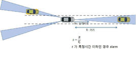
충돌에 이르기까지의 시간은 T = R(자차 및 타차량 간의 거리) / V(자차 및 타차량 간의 상대 속도)에 기초하여 도출될 수 있다. 예를 들어, TTC(Time To Collision)라는 것은 충돌 위험 상황에서 현재의 자차와 타차량 간의 거리 및 상대 속도로 도출되는 것으로, 순간의 R값과 V값은 고정으로 가정되며(cycle time이 빠르므로 1 cycle time 내에서는 R값과 V값이 고정된 값으로 가정함), TTC를 통해 그 순간의 위험도가 판단될 수 있다. 이 때, TTC를 매 cycle time(update time) 마다 계산하여 순간의 위험도를 판단할 수 있고, TTC 조건에 따라 충돌 위험을 경고할 수도 있다. The time to collision can be derived based on T = R (distance between the host vehicle and the other vehicle) / V (relative speed between the host vehicle and the other vehicle). For example, TTC (Time To Collision) is derived from the distance and relative speed between the current vehicle and other vehicles in a collision risk situation, and the R value and V value of the instant are assumed to be fixed (cycle time is fast). It is assumed that the R and V values are fixed within 1 cycle time), and the risk at that moment can be determined by TTC. At this time, the TTC may be calculated at every cycle time (update time) to determine the risk of the instant, and the risk of collision may be warned according to the TTC condition.
레이더 센서와 연산 모듈을 결합시킨 차량용 레이더 시스템은 레이더에서 감지한 위험을 운전자에게 알리기 위해, 본 발명은 운전자의 스마트폰과 같은 사용자 단말기 또는 차량 네비게이션과 연계시킬 수 있다. 스마트폰 또는 태블릿 단말기에 앱을 설치하게 하고, 상기 앱을 실행하면, 레이더 센서의 연산 모듈과 근거리 통신으로 소통할 수 있으며, 전방 출현 개체와의 충돌까지 남은 시간이 소정의 임계치에 달하면 알람을 발하게 하였다. 알람은 음성 메시지 또는 경고음으로 구현할 수 있고, 임계 시간이 단축됨에 따라 더 자주 울리거나 더 크게 울리도록 설계될 수 있다. 사용자 단말기의 화면에도 위험 표지를 표시하게 할 수 있으며, 음성 알람에 비해 상대적으로 효율이 낮지만 도로관련 정보로 축적될 수 있다. In the vehicle radar system combining the radar sensor and the calculation module to notify the driver of the risk detected by the radar, the present invention can be associated with a user terminal or a vehicle navigation, such as a smart phone of the driver. When the app is installed on a smartphone or tablet terminal, and the app is executed, the app can communicate with the arithmetic module of the radar sensor by short-range communication, and when the time remaining until the collision with the forward appearance object reaches a predetermined threshold, an alarm is issued. It was. Alarms can be implemented as voice messages or alerts, and can be designed to sound more often or louder as the threshold time is shortened. Danger signs may be displayed on the screen of the user terminal, and the efficiency may be relatively low compared to the voice alarm, but may be accumulated as road-related information.
네비게이션과 레이더 센서 연산 모듈을 연계시키는 경우, 네비게이션에서 경고음 또는 경고 메시지를 발하게 할 수 있다. 이 역시 충돌 임계 시간이 단축됨에 따라 더 자주 울리거나 더 크게 울리도록 설계될 수 있다. In the case of linking the navigation and the radar sensor calculation module, the navigation may cause a warning sound or a warning message to be issued. This may also be designed to ring more frequently or louder as the collision threshold time is shortened.
또한, 네비게이션에는 주행 도로를 포함한 지도가 표시되므로, 레이더 센서가 검출한 개체의 위치 정보를 네비게이션 지도에 표시되게 할 수 있다. 이 경우는 GPS 모듈을 설치하여 네비게이션 지도에 레이더 센서의 개체 위치정보를 얻어 표시하여야 한다. In addition, since the map including the driving road is displayed on the navigation, the location information of the object detected by the radar sensor can be displayed on the navigation map. In this case, the GPS module should be installed to obtain and display the object position information of the radar sensor on the navigation map.
한편, 레이더 센서는 기존의 블랙 박스에 설치될 수 있다. 그에 따라 본 발명은 블랙 박스와 레이더 센서를 일체형으로 제작한 차량용 레이더 시스템을 제공할 수 있다. 카메라 모듈과 레이더 센서 그리고 연산 모듈(통신 모듈 포함)이 합체되어 블랙 박스를 설치하던 장소에 설치됨으로써 전방의 영상 녹화와 더불어 위험 감지 및 경고 동작이 실시될 수 있다. Meanwhile, the radar sensor may be installed in the existing black box. Accordingly, the present invention can provide a vehicle radar system in which the black box and the radar sensor are integrally manufactured. The camera module, the radar sensor, and the calculation module (including the communication module) are combined and installed in the place where the black box was installed, so that the detection and warning operation along with the front image recording can be performed.
레이더 센서와 블랙 박스가 일체형으로 제작되는 경우, 두가지 방식을 이용하여 동작될 수 있다. 예를 들어, 하나의 프로세서(예를 들어, MCU, DSP 등)를 이용하는 경우, 레이더와 카메라(블랙 박스)를 각각 제어하여 스케쥴링할 수 있다. 다른 예를 들어, 레이더 센서와 블랙 박스 각각의 프로세서를 이용하는 경우, master-slave 구조로 동작시켜 master에서 스케쥴링이 관리되도록 할 수 있다. When the radar sensor and the black box are manufactured in one piece, it can be operated using two methods. For example, when using one processor (eg, MCU, DSP, etc.), the radar and the camera (black box) may be controlled and scheduled. As another example, when using a radar sensor and a black box processor, the master-slave structure may be used to manage scheduling in the master.
이 때, 레이더와 블랙 박스가 일체형으로 제작되는 경우, 레이더의 안테나부와 카메라의 모듈의 위치가 겹쳐지지 않아야 하며, 레이더의 안테나의 FOV(Field Of View)에 따라 빔의 왜곡이 발생하지 않도록 레이더의 위치가 고려되어야 한다. 또한, 레이더와 블랙 박스가 일체형으로 제작되는 경우, 카메라 화각, 렌즈 위치 및 형태도 고려되어야 한다. At this time, when the radar and the black box are manufactured integrally, the position of the antenna unit of the radar and the module of the camera should not overlap, and the radar does not occur according to the field of view (FOV) of the radar antenna. The position of is to be considered. In addition, when the radar and the black box are manufactured in one piece, the camera angle of view, lens position and shape should also be considered.
또한, 레이더 감지 결과, 차량의 충돌 위험 시점에 관한 임계 시간 정보를 상기 블랙박스의 영상모듈에 송신하여 위험상황을 녹화할 수 있도록 한다. 이는 블랙박스가 상시 녹화를 실시하지 않을 경우 특히 유용하고, 상시 녹화 중이더라도 위험상황을 영상에 표시하게 하는 효과를 얻을 수 있다. 경우에 따라 해당 시점에 고해상도 녹화가 이루어지게 설계할 수 있다. In addition, as a result of the radar detection, critical time information on a collision risk time of the vehicle may be transmitted to the image module of the black box to record a dangerous situation. This is particularly useful when the black box does not record at all times, and it is possible to obtain an effect of displaying a dangerous situation on an image even when recording is always performed. In some cases, a high resolution recording can be designed at a given time.
예를 들어, 차량용 레이더 시스템은 차량과 개체와의 충돌까지의 시간이 기설정된 임계값 이하인 경우, 위험 상황으로 판단하여 블랙 박스를 통해 녹화되도록 할 수 있다. 여기서, 차량용 레이더 시스템은 차량의 전방 주행뿐만 아니라, 교차로 등과 같이 주행 방향이 달라지는 경우에도 각 차량의 이동 경로를 추정하여 위험 상황(예를 들어, 충돌이 예상되는 상황)에서 충돌 경고 및 블랙 박스를 통해 위험 상황이 녹화될 수 있다. 블랙박스와 레이더 일체형이 아닐 경우에도 상기와 같은 블랙박스 연계 녹화 명령은 유용하게 적용될 수 있다. 즉, 블랙박스는 상기 통신 모듈과 근거리 통신으로 소통하여, 차량의 충돌 위험 시점에 관한 임계 시간 정보를 상기 블랙박스의 영상모듈에 송신하여 위험상황을 녹화할 수 있도록 한다.For example, the vehicle radar system may be determined to be a dangerous situation and recorded through the black box when the time until the collision between the vehicle and the object is less than or equal to a preset threshold. Here, the vehicle radar system estimates the moving path of each vehicle not only in front of the vehicle but also when the driving direction is changed such as an intersection, so that the collision warning and the black box can be detected in a dangerous situation (for example, a collision is expected). Dangerous situations can be recorded. Even when the black box and the radar are not integrated, the black box linked recording command may be usefully applied. That is, the black box communicates with the communication module through short-range communication, and transmits critical time information about a collision risk time of the vehicle to the image module of the black box, thereby recording a dangerous situation.
이와 같이, 블랙 박스를 이용하여 녹화가 이루어지는 위험 상황은 예를 들어, 상대 속도가 급변하는 경우(예를 들어, 자차의 급정지 또는 타차랑의 급정지 등), 타차량 간의 거리가 급변하는 경우(예를 들어, 제 3의 차량이 차선에 끼어드는 경우), 자차의 조향(steering)이 급격히 변하는 경우, 주변 특정 거리 내에 감지된 개체 수가 소정의 수 이상인 경우, 주변에서 감지된 개체 중 개체의 움직임이 정상적이지 않은 경우(예를 들어, 반대 차선에서 중앙선을 침범하여 오는 경우, 자차선과 멀리 떨어진 차선에서 횡방향으로 급격한 움직임을 보이는 물체를 감지한 경우 등)을 포함할 수 있다.As described above, a dangerous situation in which recording is performed by using a black box is, for example, when a relative speed changes suddenly (for example, a sudden stop of a vehicle or a sudden stop of another car), or a distance between other vehicles suddenly changes (for example, For example, when a third vehicle enters the lane), when the steering of the vehicle changes rapidly, when the number of detected objects within a certain distance is greater than a predetermined number, the movement of the objects among the detected objects around It may include cases that are not normal (for example, when an invading lane invades a centerline, or an object that detects an abrupt lateral movement in a lane far from the own lane).
상기에서, 스마트폰, 태블릿 컴퓨터 또는 네비게이션과 레이더 센서는 블루투스, NFC, 지그비와 같은 근거리 통신으로 연계될 수 있다. In the above, the smart phone, tablet computer or navigation and radar sensor may be associated with short-range communication such as Bluetooth, NFC, Zigbee.
또한, 본 발명은 차량 전방 외에 차량 후방 양 쪽에 레이더 센서를 각각 더 설치하여 차선 변경시 경고 신호를 발하게 할 수 있다. 도 1의 경우, 레이더 센서에 의한 화각(FOV: Field-of-view)는 대략 -10 내지 +10도로 하여 차량 전방에 하나, 차량 후방 양단에 각각 하나씩 설치하여 총 3개의 레이더 센서로 전방의 위험 감지와 차선 변경시 안전을 확보하게 한 구성을 보여준다. 차선 변경 시 소정의 임계 거리 이내에 개체가 감지되면 역시 사용자 단말기(스마트폰, 태블릿 컴퓨터, 네비게이션)에서 경고 알람을 발하게 한다. 이러한 구성은 근거리 통신을 이용하고 앱을 설치하거나 네비게이션에 프로그램 모듈을 설치하여 구현될 수 있다. In addition, the present invention may further install a radar sensor on both sides of the vehicle in addition to the front of the vehicle to generate a warning signal when changing lanes. In the case of Figure 1, the field-of-view (FOV) by the radar sensor is approximately -10 to +10 degrees, one at the front of the vehicle, one at each end of the rear of the vehicle, a total of three radar sensors ahead of the danger Show configuration to ensure safety during detection and lane change. If an object is detected within a predetermined threshold distance when changing lanes, the user terminal (smartphone, tablet computer, navigation) also generates a warning alarm. Such a configuration may be implemented by using near field communication and installing an app or installing a program module in a navigation.
도 2는 전방 레이더 센서와 후방 레이더 센서를 모두 하나씩 차량 중앙에 설치한 것을 보여준다. 후방의 레이더 센서는 화각이 더 넓은 것을 선택하여 설치한다. 60 내지 80m 단거리에 대해 화각 -60 내지 +60도를 발휘하는 것을 선택하여 후방에 설치한다. 상기 수치는 바람직한 일례이고 다소 변경을 가할 수 있음은 물론이다.2 shows that the front radar sensor and the rear radar sensor are all installed one by one in the center of the vehicle. The rear radar sensor selects and installs a wider field of view. It is installed at the rear by selecting the angle of view of -60 to +60 degrees for a short distance of 60 to 80m. It is a matter of course that the above figures are preferred examples and may be changed somewhat.
상기에서, 경고 방법은 경고음 발생으로 이루어지거나 사용자 앱을 통한 음성 또는 화상 경고 또는 네비게이션과 연동하여 네비게이션의 지도 화면상에서의 경고신호로 이루어질 수 있다. 사용자 단말기의 화상 또는 네비게이션 지도 화면상에서 자차에 대한 측방 또는 후방 물체와의 거리 또는 속도를 표시해주는 것 및/또는 음성 메시지로 자차에 대한 측방 또는 후방 물체와의 거리 또는 속도를 들려주는 것이다. In the above, the warning method may be made of a warning sound or a warning signal on the map screen of the navigation in conjunction with a voice or video warning or navigation through the user app. It is to display the distance or the speed with the side or rear object to the vehicle on the image or navigation map screen of the user terminal and / or to tell the distance or the speed with the side or rear object to the vehicle in a voice message.
또한, 사용자 단말기는 네비게이션 앱과 정보를 주고받아 네비게이션으로부터 지도 정보를 받아 전방 도로의 곡률 계산을 통해 전방 물체가 자차 선에 존재하는지를 판단하고 이를 사용자 단말기 화면 상에서 표시하여주거나 음성 알림하여 줄 수 있다. In addition, the user terminal may receive information from a navigation app and receive map information, determine whether a front object exists in the own vehicle line by calculating a curvature of the road ahead, and display it on the screen of the user terminal or provide a voice notification.
한편, 도 1 및 도 2에서 경고 알람은 음향 메세지, 화면 표시 외에 별도의 LED 등을 차량 내에 설치하고 점멸신호로 구현할 수도 있다. Meanwhile, in FIG. 1 and FIG. 2, the warning alarm may be implemented as a blinking signal by installing a separate LED in the vehicle in addition to the sound message and the screen display.
또한, 차량 전방 외에 차량 후방에 레이더 센서를 더 설치하여 차선 변경시 후방 또는 측방의 개체를 감지하게 하고 소정의 임계 시간 내에 개체와의 충돌이 가능하다고 판단되는 경우, 사용자 단말기에서 경고 신호를 발하게 할 수 있다. In addition, a radar sensor may be further installed at the rear of the vehicle in addition to the front of the vehicle to detect an object in the rear or side when the lane is changed, and when a collision with the object is determined within a predetermined threshold time, the user terminal may generate a warning signal. Can be.
또한, 경고 방법은 경고음 발생으로 이루어지거나 사용자 앱을 통한 음성 또는 화상 경고 또는 네비게이션과 연동하여 네비게이션의 지도 화면상에서의 경고신호로 이루어지고, 사용자 단말기의 화상 또는 네비게이션 지도 화면상에서 자차에 대한 측방 또는 후방 물체와의 거리 또는 속도를 표시해주게 할 수 있다. 본 발명의 다른 실시예에 따르면, 근거리 감지용 레이더 센서가 차량의 실내에 장착되어 운전자의 상태를 감지할 수 있다. 운전자의 상태는 예를 들어, 호흡, 심박 등의 바이탈(vital) 정보를 포함할 수 있다. In addition, the warning method is made of a warning sound or made of a warning signal on the map screen of the navigation in conjunction with voice or video warning or navigation through the user app, side or rear of the vehicle on the image or navigation map screen of the user terminal You can display the distance to the object or the speed. According to another embodiment of the present invention, a radar sensor for short range sensing may be mounted in a vehicle interior to detect a driver's condition. The driver's condition may include vital information such as, for example, breathing, heart rate, and the like.
예를 들어, 차량용 레이더 시스템은 파악된 운전자의 상태를 통해 운전자가 졸음 운전 중인 것으로 추정되는 경우, 사용자 단말기, 네비게이션 장치 등을 통해 빛, 소리, 진등 등을 이용하여 경고를 발생시킬 수 있다. 또는, 차량용 레이더 시스템은 웨어러블 디바이스와 연동하여 진동, 미세전류 등을 이용하여 경고를 발생시키거나, 운전자의 주의를 환기시키도록 할 수 있다. For example, the vehicle radar system may generate a warning by using light, sound, true light, etc. through a user terminal, a navigation device, and the like, when the driver is estimated to be drowsy driving based on the identified driver's state. Alternatively, the vehicle radar system may generate a warning using vibration, a microcurrent, or the like in conjunction with the wearable device, or may alert the driver.
다른 예를 들어, 차량용 레이더 시스템은 스마트폰과의 연동을 통해 운전자 모니터링 정보를 서버에서 수집하고, 일정 이상의 정보가 수집되면, 데이터 분석을 통해 운전시의 운전자의 생체 신호 패턴을 분석하여 안전 운전을 위한 사전 경고를 발생시키거나, 운전자의 주의를 환기시키도록 할 수 있다. 또는, 스마트폰의 네비게이션과 연동하여 운전자의 패턴에 맞는 길을 안내하여 제공하고, 적절한 휴게소 방문 시간을 안내할 수도 있다. As another example, the vehicle radar system collects driver monitoring information from a server through a linkage with a smartphone, and when more than a predetermined amount of information is collected, analyzes the driver's biosignal pattern while driving to perform safe driving. You can either give a warning or call your attention. Alternatively, in conjunction with the navigation of the smart phone, it can be provided by guiding the road according to the driver's pattern, and guide the appropriate rest stop visit time.
또 다른 예를 들어, 차량용 레이더 시스템은 운전석뿐만 아니라, 조수석까지도 감지하여 안전벨트 착용을 경고할 수 있다. 예를 들어, 운전석, 조수석에서의 시트 내부에 레이더를 장착하여 안전벨트 착용 여부를 감지하고, 이를 경고할 수 있다. In another example, a vehicle radar system may sense not only the driver's seat but also the passenger seat to warn the user of the seat belt. For example, by mounting a radar inside the seat in the driver's seat and the passenger seat, it is possible to detect whether the seat belt is worn and to warn it.
또 다른 예를 들어, 차량용 레이더 시스템은 운전석 및 조수석의 승객의 바이탈(vital)을 모니터링하여 이상 상황이 발생된 경우, 자동으로 긴급 전화(emergency call)가 걸려지도록 할 수 있다.In another example, a vehicle radar system may monitor the vitals of passengers in the driver's seat and the passenger seat to automatically make an emergency call when an abnormality occurs.
상기와 같이하여 차량의 안전 운행을 도모할 수 있는 차량용 레이더 시스템을 구현할 수 있다.As described above, a vehicle radar system capable of driving a vehicle safely can be implemented.
본 발명의 권리는 위에서 설명된 실시예에 한정되지 않고 청구범위에 기재된 바에 의해 정의되며, 본 발명의 분야에서 통상의 지식을 가진 자가 청구범위에 기재된 권리범위 내에서 다양한 변형과 개작을 할 수 있다는 것은 자명하다.The rights of the present invention are not limited to the embodiments described above, but are defined by the claims, and those skilled in the art can make various modifications and adaptations within the scope of the claims. It is self-evident.
Claims (11)
상기 레이더 센서의 송신 전자파와 수신 전자파를 분석하는 연산 모듈; 및
상기 연산 모듈의 연산 결과를 차량 내 사용자 단말기와 근거리 통신으로 소통하는 통신 모듈을 구비하고,
상기 연산 모듈은 상기 레이더 센서의 전자파 송수신 스펙트럼을 분석하여 차량과 차량 전방에 출현한 개체와의 충돌에 이르기까지의 잔여 시간을 실시간 산출하고, 충돌에 이르기까지의 잔류시간에 대해 소정의 임계 시간이 설정되어 상기 임계 시간에 도달하면 상기 사용자 단말기를 통해 경고를 발하게 하는 것을 특징으로 하는 차량용 레이더 시스템.A radar sensor mounted to the vehicle;
A calculation module for analyzing a transmission electromagnetic wave and a reception electromagnetic wave of the radar sensor; And
A communication module for communicating the calculation result of the calculation module with a user terminal in a vehicle through short-range communication;
The calculation module analyzes the electromagnetic wave transmission and reception spectrum of the radar sensor to calculate the remaining time until the collision between the vehicle and the object appearing in front of the vehicle in real time, and a predetermined threshold time for the remaining time until the collision And set a warning to alert the user terminal when the threshold time is reached.
상기 사용자 단말기는 스마트폰, 태블릿 컴퓨터, 블랙박스 또는 네비게이션을 포함하고, 상기 통신 모듈은 블루투스, NFC, 또는 지그비를 포함한 근거리 통신으로 소통하고, 상기 경고는 경고음 발성 또는 경고등 점멸 또는 경고 화면 표시를 포함하는 것을 특징으로 하는 차량용 레이더 시스템. The method of claim 1,
The user terminal includes a smart phone, a tablet computer, a black box or a navigation, the communication module communicates via short-range communication including Bluetooth, NFC, or Zigbee, and the warning includes warning sound or flashing a warning light or displaying a warning screen. Vehicle radar system, characterized in that.
상기 차량용 레이더 시스템은 블랙박스에 합체되어 블랙박스 일체형인 것을 특징으로 하는 차량용 레이더 시스템. The method of claim 1,
The radar system for a vehicle is a radar system for a vehicle, characterized in that the black box is integrated with the black box.
상기 통신 모듈은 레이더 감지 결과, 상기 차량의 충돌 위험 시점에 관한 임계 시간 정보를 상기 블랙박스의 영상모듈에 송신하고,
상기 블랙박스에 의해 위험상황을 녹화하는 것을 특징으로 하는 차량용 레이더 시스템.The method of claim 3,
The communication module, as a result of radar detection, transmits critical time information on a collision risk point of the vehicle to the image module of the black box,
Vehicle radar system, characterized in that for recording the dangerous situation by the black box.
상기 통신 모듈은 상기 사용자 단말기가 블랙박스일 경우, 상기 블랙박스와 근거리 통신으로 소통하여, 차량의 충돌 위험 시점에 관한 임계 시간 정보를 상기 블랙박스의 영상모듈에 송신하고,
상기 블랙박스에 의해 위험상황이 녹화되도록 하는 것을 특징으로 하는 차량용 레이더 시스템.The method of claim 4, wherein
When the user terminal is a black box, the communication module communicates with the black box through short-range communication to transmit critical time information on a collision risk point of the vehicle to the image module of the black box.
Vehicle radar system, characterized in that for recording the dangerous situation by the black box.
상기 연산 모듈은 GPS 모듈을 더 포함하고,
상기 통신 모듈은 근거리 통신을 통해 네비게이션 장치와 연동되고,
상기 레이더 센서에서 감지한 개체의 위치는 상기 네비게이션 장치가 표시하는 지도 위에 중첩시켜 표시되도록 하는 것을 특징으로 하는 차량용 레이더 시스템. The method of claim 1,
The calculation module further includes a GPS module,
The communication module is interlocked with the navigation device through near field communication.
Vehicle radar system, characterized in that the position of the object detected by the radar sensor is superimposed on the map displayed by the navigation device.
상기 사용자 단말기는 상기 사용자 단말기에 설치된 앱을 통해 경고 신호를 발하는 것을 특징으로 하는 차량용 레이더 시스템. The method of claim 1,
The user terminal is a vehicle radar system, characterized in that to issue a warning signal through the app installed on the user terminal.
상기 통신 모듈은 상기 레이더 센서에 의해 감지된 임계 시간 도달에 따른 경고 신호에 대한 정보를 상기 네비게이션 장치의 앱으로 전송하고,
상기 경고 신호는 상기 네비게이션 장치의 앱을 통해 발하게 되는 것인, 차량용 레이더 시스템. The method of claim 6,
The communication module transmits the information on the warning signal according to the arrival of the threshold time detected by the radar sensor to the app of the navigation device,
The warning signal is to be issued through the app of the navigation device, the vehicle radar system.
상기 사용자 단말기는 상기 네비게이션 장치의 앱과 정보를 주고받아 상기 네비게이션 장치로부터 지도 정보를 받아 전방 도로의 곡률 계산을 통해 전방 물체가 자차 선에 존재하는지를 판단하는 것을 특징으로 하는 차량용 레이더 시스템. The method of claim 8,
And the user terminal receives information from an application of the navigation device, receives map information from the navigation device, and determines whether a front object exists in the own vehicle line by calculating a curvature of the road ahead.
상기 레이더 센서는 상기 차량 전방 외에 차량의 후방에 더 설치되고,
상기 레이더 센서는 상기 차량의 차선 변경시 상기 차량의 후방 또는 측방의 개체를 감지하고,
상기 연산 모듈은 소정의 임계 시간 내에 상기 후방 또는 측방의 개체와의 추돌이 가능하다고 판단되는 경우, 상기 사용자 단말기에서 경고 신호를 발하게 하는 것을 특징으로 하는 차량용 레이더 시스템. The method of claim 1,
The radar sensor is further installed in the rear of the vehicle in addition to the front of the vehicle,
The radar sensor detects an object behind or side of the vehicle when changing the lane of the vehicle,
And the calculation module causes the user terminal to emit a warning signal when it is determined that collision with the rear or side object is possible within a predetermined threshold time.
경고 방법은 경고음 발생으로 이루어지거나 상기 사용자 단말기의 앱을 통한 음성 또는 화상 경고 또는 상기 네비게이션과 연동하여 네비게이션의 지도 화면상에서의 경고신호로 이루어지고, 상기 사용자 단말기의 화상 또는 네비게이션 지도 화면상에서 상기 차량에 대한 측방 또는 후방 개체와의 거리 또는 속도를 표시해주는 것을 특징으로 하는 차량용 레이더 시스템. The method of claim 10,
The warning method may be generated by a warning sound or a warning signal on a map screen of a navigation in conjunction with a voice or video warning through an app of the user terminal or the navigation, and may be displayed on the image or navigation map screen of the user terminal. Vehicle radar system, characterized in that for displaying the distance or speed with respect to the lateral or rear object.
Priority Applications (5)
| Application Number | Priority Date | Filing Date | Title |
|---|---|---|---|
| CN201980004792.0A CN111183367A (en) | 2018-02-23 | 2019-02-25 | Vehicle radar system for detecting dangerous goods |
| JP2020518804A JP2021520525A (en) | 2018-02-23 | 2019-02-25 | Vehicle radar system for detecting dangerous goods |
| PCT/KR2019/002288 WO2019164372A1 (en) | 2018-02-23 | 2019-02-25 | Vehicle radar system for detecting dangerous goods |
| EP19758003.8A EP3757612A4 (en) | 2018-02-23 | 2019-02-25 | Vehicle radar system for detecting dangerous goods |
| US16/830,786 US20200225343A1 (en) | 2018-02-23 | 2020-03-26 | Vehicle radar system for detecting dangerous goods |
Applications Claiming Priority (2)
| Application Number | Priority Date | Filing Date | Title |
|---|---|---|---|
| KR1020180021661 | 2018-02-23 | ||
| KR20180021661 | 2018-02-23 |
Publications (1)
| Publication Number | Publication Date |
|---|---|
| KR20190101909A true KR20190101909A (en) | 2019-09-02 |
Family
ID=67951464
Family Applications (1)
| Application Number | Title | Priority Date | Filing Date |
|---|---|---|---|
| KR1020190021399A KR20190101909A (en) | 2018-02-23 | 2019-02-22 | Viechle radar system for sensing danger |
Country Status (5)
| Country | Link |
|---|---|
| US (1) | US20200225343A1 (en) |
| EP (1) | EP3757612A4 (en) |
| JP (1) | JP2021520525A (en) |
| KR (1) | KR20190101909A (en) |
| CN (1) | CN111183367A (en) |
Cited By (2)
| Publication number | Priority date | Publication date | Assignee | Title |
|---|---|---|---|---|
| KR20200046136A (en) * | 2018-10-10 | 2020-05-07 | 현대자동차주식회사 | Apparatus and method for identificating short cut in vehicle and vehicle including the same |
| KR20210041770A (en) | 2019-10-08 | 2021-04-16 | 주식회사 제이씨레이다 | Smart mobility detection radar |
Families Citing this family (6)
| Publication number | Priority date | Publication date | Assignee | Title |
|---|---|---|---|---|
| US11840252B2 (en) * | 2019-03-15 | 2023-12-12 | Honda Motor Co., Ltd. | Vehicle communications device and non-transitory computer-readable recording medium storing program |
| WO2020188942A1 (en) * | 2019-03-15 | 2020-09-24 | 本田技研工業株式会社 | Vehicle communication device and program |
| US11491976B2 (en) * | 2020-04-21 | 2022-11-08 | Baidu Usa Llc | Collision warning system for safety operators of autonomous vehicles |
| US20220051493A1 (en) * | 2020-08-14 | 2022-02-17 | Kennith Burks | Systems and methods for an automobile status recorder |
| CN113208438B (en) * | 2021-06-24 | 2022-09-06 | 合肥美菱物联科技有限公司 | Early warning system and method for preventing kettle from toppling over in tea bar machine |
| CN113903142B (en) * | 2021-09-24 | 2022-12-06 | 广州智伴人工智能科技有限公司 | Method and system for monitoring outdoor state of child for intelligent accompanying robot |
Family Cites Families (17)
| Publication number | Priority date | Publication date | Assignee | Title |
|---|---|---|---|---|
| US7421321B2 (en) * | 1995-06-07 | 2008-09-02 | Automotive Technologies International, Inc. | System for obtaining vehicular information |
| US6592230B2 (en) * | 1997-10-16 | 2003-07-15 | Holland Hitch Company | Truck rearview mirror assembly having a display for displaying trailer coupling status information |
| US7796081B2 (en) * | 1997-10-22 | 2010-09-14 | Intelligent Technologies International, Inc. | Combined imaging and distance monitoring for vehicular applications |
| JP3658519B2 (en) * | 1999-06-28 | 2005-06-08 | 株式会社日立製作所 | Vehicle control system and vehicle control device |
| DE102009057191A1 (en) * | 2009-12-05 | 2011-06-09 | Valeo Schalter Und Sensoren Gmbh | Method for uniquely determining a distance and / or a relative speed of an object, driver assistance device and motor vehicle |
| CN201936364U (en) * | 2011-01-17 | 2011-08-17 | 杨静慧 | Traveling recorder with speed measuring and image recording functions |
| CN102289952B (en) * | 2011-07-15 | 2014-11-26 | 黄克 | Vehicle anti-collision method based on satellite navigation system and navigation system and application thereof |
| KR101300534B1 (en) * | 2012-02-29 | 2013-09-02 | 주경희 | Method for displaying distance between cars and warning bumping danger of cars using wireless radar and apparatus using it |
| JP5939170B2 (en) * | 2013-01-17 | 2016-06-22 | 株式会社デンソー | Object approach notification system |
| JP6355234B2 (en) * | 2013-04-09 | 2018-07-11 | 株式会社ユピテル | Image recording apparatus, image recording system, and program |
| CN104369670B (en) * | 2013-08-15 | 2017-05-24 | 深圳市赛格导航科技股份有限公司 | Vehicle speed control method and system |
| KR101484618B1 (en) * | 2014-03-24 | 2015-01-21 | (주)디지탈엣지 | Management system and method of radar apparatus |
| KR20160091040A (en) * | 2015-01-23 | 2016-08-02 | 엘지전자 주식회사 | Vehicle and Control Method Thereof |
| JP6056069B2 (en) * | 2015-09-17 | 2017-01-11 | 株式会社ユピテル | Drive recorder body and equipment |
| JP6211043B2 (en) * | 2015-11-05 | 2017-10-11 | 三菱電機株式会社 | Vehicle collision prevention device |
| JP2017107475A (en) * | 2015-12-11 | 2017-06-15 | セルスター工業株式会社 | On-vehicle system and drive recorder |
| JP6132327B1 (en) * | 2016-09-12 | 2017-05-24 | Kenpal株式会社 | Operation management support system, operation management method, server device, and program |
-
2019
- 2019-02-22 KR KR1020190021399A patent/KR20190101909A/en not_active Application Discontinuation
- 2019-02-25 EP EP19758003.8A patent/EP3757612A4/en not_active Withdrawn
- 2019-02-25 JP JP2020518804A patent/JP2021520525A/en active Pending
- 2019-02-25 CN CN201980004792.0A patent/CN111183367A/en active Pending
-
2020
- 2020-03-26 US US16/830,786 patent/US20200225343A1/en not_active Abandoned
Cited By (2)
| Publication number | Priority date | Publication date | Assignee | Title |
|---|---|---|---|---|
| KR20200046136A (en) * | 2018-10-10 | 2020-05-07 | 현대자동차주식회사 | Apparatus and method for identificating short cut in vehicle and vehicle including the same |
| KR20210041770A (en) | 2019-10-08 | 2021-04-16 | 주식회사 제이씨레이다 | Smart mobility detection radar |
Also Published As
| Publication number | Publication date |
|---|---|
| EP3757612A4 (en) | 2021-11-17 |
| CN111183367A (en) | 2020-05-19 |
| JP2021520525A (en) | 2021-08-19 |
| US20200225343A1 (en) | 2020-07-16 |
| EP3757612A1 (en) | 2020-12-30 |
Similar Documents
| Publication | Publication Date | Title |
|---|---|---|
| KR20190101909A (en) | Viechle radar system for sensing danger | |
| CN106683464B (en) | System and method for providing alerts to a vehicle based on vehicle dynamic inputs | |
| US10127815B2 (en) | Method and device for setting up a movement model of a road user | |
| US20180232962A1 (en) | Driver Behavior Monitoring | |
| US8669857B2 (en) | Hand-held device integration for automobile safety | |
| US7852233B2 (en) | Driver notification system, device, and associated method | |
| US6442484B1 (en) | Method and apparatus for pre-crash threat assessment using spheroidal partitioning | |
| JP2017527939A (en) | Method and apparatus for monitoring traffic areas | |
| US20030225511A1 (en) | Vehicle recognition support system | |
| CN108307295A (en) | The method and apparatus for avoiding accident for vulnerable road user | |
| US10192443B2 (en) | Collision avoidance system and collision avoidance method | |
| CN106164698B (en) | Radar module, conveying equipment and object identification method | |
| JP2018513504A (en) | Proximity recognition system for automobiles | |
| US10657808B2 (en) | Vehicular communication system | |
| CN112771592B (en) | Method for warning a driver of a motor vehicle, control device and motor vehicle | |
| WO2019060891A1 (en) | Augmented reality dsrc data visualization | |
| CN105336216A (en) | Unsignalized intersection anti-collision early warning method and terminal | |
| US20170096105A1 (en) | Method for providing an alert to a driver and an alert system | |
| EP2279889B1 (en) | Method and system for shoulder departure assistance in an automotive vehicle | |
| CN108831189A (en) | A kind of intelligent early-warning method based on millimetre-wave radar anticollision | |
| WO2019164372A1 (en) | Vehicle radar system for detecting dangerous goods | |
| JP2006072725A (en) | On-vehicle system | |
| CN214355775U (en) | Display device of automatic driving vehicle, automobile central control and automatic driving vehicle | |
| JP2022100852A (en) | Attention evocation device and attention evocation method | |
| JP2011034333A (en) | Driving support device for vehicle |
Legal Events
| Date | Code | Title | Description |
|---|---|---|---|
| E902 | Notification of reason for refusal | ||
| E601 | Decision to refuse application |