US6643588B1 - Geometric based path prediction method using moving and stop objects - Google Patents
Geometric based path prediction method using moving and stop objects Download PDFInfo
- Publication number
- US6643588B1 US6643588B1 US10/120,676 US12067602A US6643588B1 US 6643588 B1 US6643588 B1 US 6643588B1 US 12067602 A US12067602 A US 12067602A US 6643588 B1 US6643588 B1 US 6643588B1
- Authority
- US
- United States
- Prior art keywords
- vehicle
- host vehicle
- angle
- host
- target
- Prior art date
- Legal status (The legal status is an assumption and is not a legal conclusion. Google has not performed a legal analysis and makes no representation as to the accuracy of the status listed.)
- Expired - Fee Related
Links
- 238000000034 method Methods 0.000 title claims abstract description 46
- 238000005259 measurement Methods 0.000 description 11
- 230000003044 adaptive effect Effects 0.000 description 9
- 230000001133 acceleration Effects 0.000 description 3
- 230000008901 benefit Effects 0.000 description 2
- 238000010586 diagram Methods 0.000 description 2
- 230000000694 effects Effects 0.000 description 2
- 230000005540 biological transmission Effects 0.000 description 1
- 238000004891 communication Methods 0.000 description 1
- 238000007796 conventional method Methods 0.000 description 1
- 230000007423 decrease Effects 0.000 description 1
- 230000026058 directional locomotion Effects 0.000 description 1
- 230000004927 fusion Effects 0.000 description 1
- 238000003384 imaging method Methods 0.000 description 1
- 238000012986 modification Methods 0.000 description 1
- 230000004048 modification Effects 0.000 description 1
Images


Classifications
-
- B—PERFORMING OPERATIONS; TRANSPORTING
- B60—VEHICLES IN GENERAL
- B60W—CONJOINT CONTROL OF VEHICLE SUB-UNITS OF DIFFERENT TYPE OR DIFFERENT FUNCTION; CONTROL SYSTEMS SPECIALLY ADAPTED FOR HYBRID VEHICLES; ROAD VEHICLE DRIVE CONTROL SYSTEMS FOR PURPOSES NOT RELATED TO THE CONTROL OF A PARTICULAR SUB-UNIT
- B60W40/00—Estimation or calculation of non-directly measurable driving parameters for road vehicle drive control systems not related to the control of a particular sub unit, e.g. by using mathematical models
- B60W40/02—Estimation or calculation of non-directly measurable driving parameters for road vehicle drive control systems not related to the control of a particular sub unit, e.g. by using mathematical models related to ambient conditions
- B60W40/06—Road conditions
- B60W40/072—Curvature of the road
-
- B—PERFORMING OPERATIONS; TRANSPORTING
- B60—VEHICLES IN GENERAL
- B60W—CONJOINT CONTROL OF VEHICLE SUB-UNITS OF DIFFERENT TYPE OR DIFFERENT FUNCTION; CONTROL SYSTEMS SPECIALLY ADAPTED FOR HYBRID VEHICLES; ROAD VEHICLE DRIVE CONTROL SYSTEMS FOR PURPOSES NOT RELATED TO THE CONTROL OF A PARTICULAR SUB-UNIT
- B60W30/00—Purposes of road vehicle drive control systems not related to the control of a particular sub-unit, e.g. of systems using conjoint control of vehicle sub-units
- B60W30/14—Adaptive cruise control
- B60W30/16—Control of distance between vehicles, e.g. keeping a distance to preceding vehicle
-
- B—PERFORMING OPERATIONS; TRANSPORTING
- B60—VEHICLES IN GENERAL
- B60K—ARRANGEMENT OR MOUNTING OF PROPULSION UNITS OR OF TRANSMISSIONS IN VEHICLES; ARRANGEMENT OR MOUNTING OF PLURAL DIVERSE PRIME-MOVERS IN VEHICLES; AUXILIARY DRIVES FOR VEHICLES; INSTRUMENTATION OR DASHBOARDS FOR VEHICLES; ARRANGEMENTS IN CONNECTION WITH COOLING, AIR INTAKE, GAS EXHAUST OR FUEL SUPPLY OF PROPULSION UNITS IN VEHICLES
- B60K31/00—Vehicle fittings, acting on a single sub-unit only, for automatically controlling vehicle speed, i.e. preventing speed from exceeding an arbitrarily established velocity or maintaining speed at a particular velocity, as selected by the vehicle operator
- B60K31/0008—Vehicle fittings, acting on a single sub-unit only, for automatically controlling vehicle speed, i.e. preventing speed from exceeding an arbitrarily established velocity or maintaining speed at a particular velocity, as selected by the vehicle operator including means for detecting potential obstacles in vehicle path
-
- B—PERFORMING OPERATIONS; TRANSPORTING
- B60—VEHICLES IN GENERAL
- B60W—CONJOINT CONTROL OF VEHICLE SUB-UNITS OF DIFFERENT TYPE OR DIFFERENT FUNCTION; CONTROL SYSTEMS SPECIALLY ADAPTED FOR HYBRID VEHICLES; ROAD VEHICLE DRIVE CONTROL SYSTEMS FOR PURPOSES NOT RELATED TO THE CONTROL OF A PARTICULAR SUB-UNIT
- B60W2552/00—Input parameters relating to infrastructure
- B60W2552/20—Road profile, i.e. the change in elevation or curvature of a plurality of continuous road segments
-
- B—PERFORMING OPERATIONS; TRANSPORTING
- B60—VEHICLES IN GENERAL
- B60W—CONJOINT CONTROL OF VEHICLE SUB-UNITS OF DIFFERENT TYPE OR DIFFERENT FUNCTION; CONTROL SYSTEMS SPECIALLY ADAPTED FOR HYBRID VEHICLES; ROAD VEHICLE DRIVE CONTROL SYSTEMS FOR PURPOSES NOT RELATED TO THE CONTROL OF A PARTICULAR SUB-UNIT
- B60W2552/00—Input parameters relating to infrastructure
- B60W2552/30—Road curve radius
Definitions
- the present invention relates to systems and methods for predicting the path of a host vehicle for safety and non-safety automotive applications, such as adaptive cruise control (ACC).
- ACC adaptive cruise control
- Adaptive cruise control systems are gaining wide spread acceptance in vehicles today.
- Adaptive cruise control (ACC) systems utilize a conventional cruise control system, which maintains a desired vehicle speed.
- the adaptive cruise control system can modify the speed of the vehicle to accommodate for changes in traffic conditions.
- the ACC system accomplishes this through automatic acceleration, deceleration and/or braking.
- the vehicle having the ACC system (which will be referred to herein as the host vehicle) maintains a safe distance from the vehicle driving directly in front of the host vehicle (this vehicle will be referred to the target vehicle) as a function of road speed.
- prior art adaptive cruise control systems include an adaptive cruise control processor, a radar sensor, a brake intervention system, a display unit, an engine intervention system, a plurality of sensors (i.e., wheel speed, yaw rate, steering wheel angle, lateral acceleration), and a transmission intervention system.
- the radar sensor operates at a frequency of 76 to 77 gigahertz, which was specifically allocated for ACC systems.
- radar beam is emitted by the host vehicle and is reflected off of the target vehicle back toward the host vehicle.
- the propagation time, dopier shift, and amplitude of the emitted and reflected radar waves are compared. From this comparison, the range or distance, relative speed and relative position between the target and host vehicles are calculated.
- One significant problem for ACC systems to overcome is to ensure reliable operation of the system in varying situations such as curves in the road and/or during lane changes. For proper system operation, it is essential that the target vehicle is correctly identified and the lane in which the target vehicle is located is also identified.
- Prior art systems obtain information from a yaw rate sensor, a steering wheel angle sensor, wheel speed sensors, and lateral speed sensors to determine the target vehicle's lane location and curve status.
- Other systems under consideration for determining vehicle location are video imaging systems.
- the shortcomings of this method are: first, the path or curvature of the road cannot be accurately predicted and second, any prediction is highly affected by the driver behavior.
- the first shortcoming is due to the fact that the calculated curvature from the yaw rate and the speed measurements represents the road curvature at the host vehicle position, and the sensors used have different kinds of measurements errors.
- the latter shortcoming is due to driver habit where he or she doesn't follow the road curvature, e.g., during a lane change.
- Other prior art methods that use target information to estimate the curvature of the road assume that the host vehicle is always following the road. Therefore, these methods fail when a host vehicle maneuvers or changes lanes.
- the method of the present invention utilizes what will be referred to as a projected host vehicle reference frame.
- the projected host reference frame results from rotating a host vehicle reference frame to align the host vehicle reference frame with a road reference frame. This is achieved by determining whether the host vehicle is changing lanes and accounting for a heading angle of the host vehicle with respect to the road.
- the present invention utilizes stopped and moving objects to obtain the maximum benefit of the existing objects in the radar field of view. Moving objects are perceived in two ways, first as moving object with history, and second as a stopped object at the current time. Also, the stopped objects such as a guardrail or a row of trees on a road side can perceived as a fictitious moving object that travels at the host vehicle speed.
- a method for estimating the curvature in a road uses an azimuth angle range and relative velocity between a host and a target vehicle radar measurement to determine whether the host vehicle is changing lanes or whether the target vehicle is changing lanes.
- the method calculates a heading angle of the host vehicle and calculates a corrected azimuth angle by adjusting the measured azimuth angle by the value of calculated heading angle
- the method selects a curve that minimizes the mean square error between the curve and selected targets, and determines an equation that describes the curve, wherein the equation is used to predict the path ahead of the host vehicle.
- FIG. 1 illustrates a host vehicle having an adaptive cruise control (ACC) system, in accordance with the present invention
- FIG. 2 illustrates a host vehicle following or tracking a target vehicle, in accordance with the present invention
- FIG. 3 is a schematic diagram of a host vehicle traveling along a road following target vehicles at a time “k” and “k+1”, in accordance with the present invention
- FIG. 4 illustrates a host vehicle tracking a group of targets along a path preceding the host vehicle
- FIG. 5 is a flowchart illustrating the method for determining the curvature of a road.
- Adaptive cruise control system 12 includes a plurality of vehicle sensors for measuring various vehicle dynamics parameters.
- ACC system 12 includes a yaw rate sensor 14 for measuring the yaw rate of host vehicle 10 .
- Other vehicle sensors include a speed sensor 16 , for measuring vehicle speed, and a range sensor 18 for detecting objects and other vehicles (target vehicles) in front of host vehicle 10 .
- ACC system 12 includes, a control module 20 mounted within host vehicle 10 and in communication with the various sensors, just described, as well as vehicle subsystems such as the vehicle braking system 24 and the vehicle acceleration system (not shown).
- a controlled area network (CAN) bus 26 interconnects the various sensors and vehicle subsystems to control module 20 .
- CAN controlled area network
- FIG. 2 is a diagram depicting host vehicle 10 following or tracking a target vehicle 30 .
- Range sensor 18 preferably is a radar sensor that provides relative speed, azimuth angle and distance information of target vehicle 30 or a plurality of vehicles or other objects in the path of host vehicle 10 .
- a fixed radar beam 32 having a frequency of 76 GHz is transmitted from radar sensor 18 for detecting moving objects such as target vehicle 30 , as well as stopped objects such as guardrail 34 .
- ACC system 12 automatically adjusts the host vehicle's speed and then returns host vehicle 10 to the set or desired speed after the traffic clears.
- the ACC system 12 in order to operate properly must determine, out of all of the vehicles and objects in front of the host, which vehicle is the primary target. In order to identify the primary in-lane target vehicle, a reliable estimation of road curvature ahead of the vehicle must be determined.
- FIG. 3 a diagrammatic representation of host vehicle 10 equipped with an ACC system 12 is illustrated traveling along a road 50 , wherein road 50 has a left lane 52 and a right lane 54 . Host vehicle 10 is further shown following a target vehicle 30 . Further, road 50 is curved and has a radius of curvature “r” about a center point 56 . As host vehicle 10 travels on road 52 , radar sensor 18 measures the range, azimuth angle and relative velocity between host vehicle 10 and target vehicle 30 which is in the same left lane 52 of road 50 as the host vehicle. These radar measurements occur at a time “k” and at a time “k+1”. At time “k+1” host vehicle 10 has moved into right lane 54 of road 50 and as illustrated target vehicle 30 also has also moved into lane 54 .
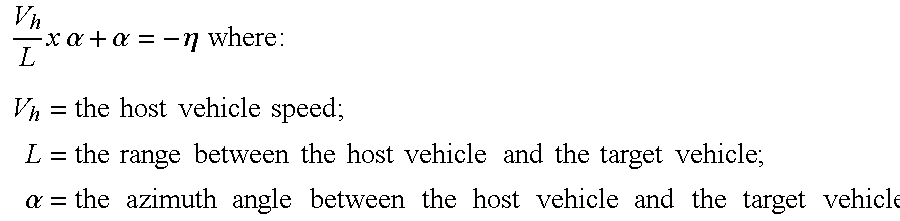
- FIG. 3 further illustrates azimuth angle “ ⁇ ” and heading angle “ ⁇ ”.
- Heading angle “ ⁇ ” is a result of the directional motion of host vehicle 10 from a first position “p(k)” to a position “p(k+1)” on road 50 .
- the azimuth angle “ ⁇ ” is a function of geometry and orientation of host vehicle 10 with respect to the road 50 .
- the geometry factor is a result of the relative lateral distance between host vehicle 10 and target vehicle 30 , as well as the range between them.
- the orientation of host vehicle 10 with respect to the road is effected by the maneuvering of host vehicle 10 with respect to road 50 .
- the azimuth angle varies as the host vehicle is rotating around its axis even though the geometry is not changing.
- any maneuvering of host vehicle 10 with respect to the road 50 affects the azimuth angle by both the geometry factor and the orientation factor.
- the maneuvering of the target vehicle with respect to the road effects the azimuth angle measurement by the geometry factor only. Therefore, the geometry factor variation is a combined result of the host and target vehicle maneuvering.
- a method for predicting road curvature is provided. As will be described hereinafter, this method accounts for host vehicle maneuvering, target vehicle maneuvering, and changes in the curvature of the road.
- the present invention assumes that the curvature of the road remains constant between time samples “k” and “k+1”. Thus, the variation in the curvature of the road is neglected. The inventor of the present invention believes this to be a valid assumption since the road curvature doesn't change rapidly. Furthermore, the curvature of the road is presumed to follow a circle.
- the present invention addresses the difficult task of distinguishing between a host vehicle maneuvering and a lead vehicle maneuvering. This task is not trivial since both types of vehicle maneuvering have almost a similar effect on the azimuth angle measurement.
- One method is to look to the yaw rate measurement of the host vehicle. This method, however, is not reliable for two reasons: the first by the difficulty of distinguishing the source of the yaw rate, i.e., is it a result of a curve, lane change, or just a yaw rate bias, and second by the noise and drift imposed on the yaw rate measurement.
- host vehicle 10 has a group of targets 60 , 62 and 64 located at points xi and yi along a path preceding host vehicle 10 . Furthermore, host vehicle 10 has a heading angle “ ⁇ ” that is defined as the angle between a line tangent to the road and a direction the host vehicle is heading in. A unique azimuth angle “ ⁇ ” is associated with each target 60 , 62 and 64 . Thus, an azimuth angle ⁇ ′ is the angle between the road's tangent line and a line drawn between the host vehicle 10 and target 60 .
- azimuth angle ⁇ ′′ is the angle between the road's tangent line and the line drawn between host vehicle 10 and target 62 .
- azimuth angle ⁇ ′′ is defined as the angle between the road's tangent line and a line drawn between host vehicle 10 and target 64 .
- the method for determining the curvature of a road is further illustrated.
- the method is initiated at block 70 , and at block 72 , the ACC system of the host vehicle measures the range, azimuth angle, and relative velocity between the host vehicle 10 and each target. It is first determined whether the target object, target vehicle or vehicles are maneuvering, at block 74 . At block 76 , it is determined whether the host vehicle is maneuvering. The method determines whether the target or host vehicles are maneuvering by following predefined rule: (1) the host vehicle is maneuvering, when all of the azimuth angle measurements of all of the targets change in the same way; or (2) that the target vehicle is maneuvering, when only the azimuth angle of that target is changing and the azimuth angles of the other targets are not changing.
- the targets coordinates of each target are mapped, as represented by block 82 . Further, the method corrects the mapped target coordinates by adjusting (rotating) the mapped target coordinates by the calculated heading angle, as represented by block 84 .
- the curvature of the road is calculated fitting a curve through the mapped target coordinates x i and y j . An optimal curve is selected that minimizes the mean square error of the differences between the curve and each target location. The curve is constrained to be a circle.
- a conventional method for calculating road curvature using yaw rate is utilized to identify an alternate road curvature calculation.
- This conventional curvature calculation using yaw rate is for example, similar to the method disclosed in U.S. Pat. No. 5,926,126 entitled “Method And System For Detecting An In-Path Target Obstacle In Front Of A Vehicle” and is incorporated herein by reference.
- a final road curvature is calculated by fusing (combining) the two calculations mv,x.z.
- Fusion of the yaw rate based road curvature calculation and target based road curvature calculation is achieved by following the following rule as the change in the yaw rate increases the weight of the yaw-rate based curvature decreases, and as the number of targets increases the weight of the target based curvature increases.
Landscapes
- Engineering & Computer Science (AREA)
- Transportation (AREA)
- Mechanical Engineering (AREA)
- Chemical & Material Sciences (AREA)
- Combustion & Propulsion (AREA)
- Automation & Control Theory (AREA)
- Physics & Mathematics (AREA)
- Mathematical Physics (AREA)
- Radar Systems Or Details Thereof (AREA)
- Traffic Control Systems (AREA)
Abstract
Description


Claims (13)

Priority Applications (2)
| Application Number | Priority Date | Filing Date | Title |
|---|---|---|---|
| US10/120,676 US6643588B1 (en) | 2002-04-11 | 2002-04-11 | Geometric based path prediction method using moving and stop objects |
| GB0304553A GB2390244B (en) | 2002-04-11 | 2003-02-28 | Geometric based path prediction method using moving and stop objects |
Applications Claiming Priority (1)
| Application Number | Priority Date | Filing Date | Title |
|---|---|---|---|
| US10/120,676 US6643588B1 (en) | 2002-04-11 | 2002-04-11 | Geometric based path prediction method using moving and stop objects |
Publications (2)
| Publication Number | Publication Date |
|---|---|
| US20030195703A1 US20030195703A1 (en) | 2003-10-16 |
| US6643588B1 true US6643588B1 (en) | 2003-11-04 |
Family
ID=22391843
Family Applications (1)
| Application Number | Title | Priority Date | Filing Date |
|---|---|---|---|
| US10/120,676 Expired - Fee Related US6643588B1 (en) | 2002-04-11 | 2002-04-11 | Geometric based path prediction method using moving and stop objects |
Country Status (2)
| Country | Link |
|---|---|
| US (1) | US6643588B1 (en) |
| GB (1) | GB2390244B (en) |
Cited By (11)
| Publication number | Priority date | Publication date | Assignee | Title |
|---|---|---|---|---|
| US20030070851A1 (en) * | 2000-04-14 | 2003-04-17 | Hermann Winner | Method for adjusting the speed of a motor vehicle |
| US20050179580A1 (en) * | 2002-07-15 | 2005-08-18 | Shan Cong | Road curvature estimation and automotive target state estimation system |
| US20050278112A1 (en) * | 2004-06-14 | 2005-12-15 | Axel Gern | Process for predicting the course of a lane of a vehicle |
| US20080183419A1 (en) * | 2002-07-15 | 2008-07-31 | Automotive Systems Laboratory, Inc. | Road curvature estimation system |
| US20100076684A1 (en) * | 2008-09-24 | 2010-03-25 | Schiffmann Jan K | Probabilistic lane assignment method |
| US20100271256A1 (en) * | 2008-12-05 | 2010-10-28 | Toyota Jidosha Kabushiki Kaisha | Pre-crash safety system |
| US20110301845A1 (en) * | 2009-01-29 | 2011-12-08 | Toyota Jidosha Kabushiki Kaisha | Object recognition device and object recognition method |
| US8650000B2 (en) | 2010-01-15 | 2014-02-11 | The United States Of America As Represented By The Secretary Of The Navy | Ballistic missile phase categorization technique |
| US8914253B2 (en) | 2010-01-15 | 2014-12-16 | The United States Of America As Represented By The Secretary Of The Navy | Aerial bogey discrimination technique |
| US20160121892A1 (en) * | 2013-06-18 | 2016-05-05 | Continental Automotive Gmbh | Method and device for determining a driving state of an external motor vehicle |
| US20200092366A1 (en) * | 2018-09-18 | 2020-03-19 | At&T Intellectual Property I, L.P. | Peer Packet Transport |
Families Citing this family (13)
| Publication number | Priority date | Publication date | Assignee | Title |
|---|---|---|---|---|
| WO2005062984A2 (en) * | 2003-12-24 | 2005-07-14 | Automotive Systems Laboratory, Inc. | Road curvature estimation system |
| US8775063B2 (en) * | 2009-01-26 | 2014-07-08 | GM Global Technology Operations LLC | System and method of lane path estimation using sensor fusion |
| JP5601224B2 (en) * | 2010-03-04 | 2014-10-08 | 株式会社デンソー | Road shape learning device |
| DE102010021561A1 (en) * | 2010-05-26 | 2011-12-01 | Gm Global Technology Operations Llc (N.D.Ges.D. Staates Delaware) | Method for vehicle steering with a vehicle steering device |
| JP5278419B2 (en) * | 2010-12-17 | 2013-09-04 | 株式会社デンソー | Driving scene transition prediction device and vehicle recommended driving operation presentation device |
| DE102011102437A1 (en) * | 2011-05-25 | 2012-11-29 | Audi Ag | Method for operating a longitudinal driver assistance system of a motor vehicle and motor vehicle |
| JP6054638B2 (en) * | 2012-05-30 | 2016-12-27 | クラリオン株式会社 | Vehicle position detection device and program |
| US9562779B2 (en) * | 2014-12-23 | 2017-02-07 | Here Global B.V. | Method and apparatus for providing a steering reliability map based on driven curvatures and geometry curvature |
| DE112016005235T5 (en) * | 2015-12-17 | 2018-08-02 | Scania Cv Ab | METHOD AND SYSTEM FOR FOLLOWING A TRACK OF A VEHICLE ALONG A STREET |
| DE112016005304T5 (en) * | 2015-12-17 | 2018-08-02 | Scania Cv Ab | A method and system for facilitating the following of a Leader Vehicle along a road |
| US10121367B2 (en) * | 2016-04-29 | 2018-11-06 | Ford Global Technologies, Llc | Vehicle lane map estimation |
| EP3805064B8 (en) * | 2018-03-20 | 2024-07-17 | Mobileye Vision Technologies Ltd. | Modified responsibility sensitivity safety model |
| CN111469841B (en) * | 2020-04-24 | 2021-12-14 | 驭势(上海)汽车科技有限公司 | Curve target selection method, vehicle-mounted equipment and storage medium |
Citations (7)
| Publication number | Priority date | Publication date | Assignee | Title |
|---|---|---|---|---|
| US4158841A (en) * | 1976-05-26 | 1979-06-19 | Daimler-Benz Aktiengesellschaft | Method and apparatus for the control of the safety distance of a vehicle relative to preceding vehicles |
| US5926126A (en) | 1997-09-08 | 1999-07-20 | Ford Global Technologies, Inc. | Method and system for detecting an in-path target obstacle in front of a vehicle |
| US5964822A (en) * | 1997-08-27 | 1999-10-12 | Delco Electronics Corp. | Automatic sensor azimuth alignment |
| US6025797A (en) * | 1997-07-22 | 2000-02-15 | Denso Corporation | Angular shift determining apparatus for determining angular shift of central axis of radar used in automotive obstacle detection system |
| US6070121A (en) | 1997-05-26 | 2000-05-30 | Honda Giken Kogyo Kabushiki Kaisha | Road shape determining device and vehicle control system |
| US6292752B1 (en) * | 1997-11-06 | 2001-09-18 | Daimlerchrysler Ag | Device for acquiring lane path indicative data |
| US20020016663A1 (en) * | 1999-06-28 | 2002-02-07 | Hitachi, Ltd. | Vehicle control method and vehicle warning method |
Family Cites Families (3)
| Publication number | Priority date | Publication date | Assignee | Title |
|---|---|---|---|---|
| JP3822770B2 (en) * | 1999-12-10 | 2006-09-20 | 三菱電機株式会社 | Vehicle front monitoring device |
| JP3681620B2 (en) * | 2000-07-26 | 2005-08-10 | 株式会社デンソー | Obstacle recognition device for vehicles |
| EP1315980B1 (en) * | 2000-09-08 | 2006-10-04 | Raytheon Company | Path prediction system and method |
-
2002
- 2002-04-11 US US10/120,676 patent/US6643588B1/en not_active Expired - Fee Related
-
2003
- 2003-02-28 GB GB0304553A patent/GB2390244B/en not_active Expired - Fee Related
Patent Citations (8)
| Publication number | Priority date | Publication date | Assignee | Title |
|---|---|---|---|---|
| US4158841A (en) * | 1976-05-26 | 1979-06-19 | Daimler-Benz Aktiengesellschaft | Method and apparatus for the control of the safety distance of a vehicle relative to preceding vehicles |
| US6070121A (en) | 1997-05-26 | 2000-05-30 | Honda Giken Kogyo Kabushiki Kaisha | Road shape determining device and vehicle control system |
| US6025797A (en) * | 1997-07-22 | 2000-02-15 | Denso Corporation | Angular shift determining apparatus for determining angular shift of central axis of radar used in automotive obstacle detection system |
| US5964822A (en) * | 1997-08-27 | 1999-10-12 | Delco Electronics Corp. | Automatic sensor azimuth alignment |
| US6202027B1 (en) | 1997-08-27 | 2001-03-13 | Delphi Technologies, Inc. | Automatic curve sensor calibration method for an automotive CW/ICC system |
| US5926126A (en) | 1997-09-08 | 1999-07-20 | Ford Global Technologies, Inc. | Method and system for detecting an in-path target obstacle in front of a vehicle |
| US6292752B1 (en) * | 1997-11-06 | 2001-09-18 | Daimlerchrysler Ag | Device for acquiring lane path indicative data |
| US20020016663A1 (en) * | 1999-06-28 | 2002-02-07 | Hitachi, Ltd. | Vehicle control method and vehicle warning method |
Cited By (21)
| Publication number | Priority date | Publication date | Assignee | Title |
|---|---|---|---|---|
| US6763904B2 (en) * | 2000-04-14 | 2004-07-20 | Robert Bosch Gmbh | Method for adjusting the speed of a motor vehicle |
| US20030070851A1 (en) * | 2000-04-14 | 2003-04-17 | Hermann Winner | Method for adjusting the speed of a motor vehicle |
| US20050179580A1 (en) * | 2002-07-15 | 2005-08-18 | Shan Cong | Road curvature estimation and automotive target state estimation system |
| US7034742B2 (en) * | 2002-07-15 | 2006-04-25 | Automotive Systems Laboratory, Inc. | Road curvature estimation and automotive target state estimation system |
| US20080183419A1 (en) * | 2002-07-15 | 2008-07-31 | Automotive Systems Laboratory, Inc. | Road curvature estimation system |
| US7522091B2 (en) | 2002-07-15 | 2009-04-21 | Automotive Systems Laboratory, Inc. | Road curvature estimation system |
| US7626533B2 (en) | 2002-07-15 | 2009-12-01 | Automotive Systems Laboratory, Inc. | Road curvature estimation system |
| US20050278112A1 (en) * | 2004-06-14 | 2005-12-15 | Axel Gern | Process for predicting the course of a lane of a vehicle |
| DE102004028404A1 (en) * | 2004-06-14 | 2006-01-19 | Daimlerchrysler Ag | Method for estimating the course of a lane of a motor vehicle |
| US8055445B2 (en) * | 2008-09-24 | 2011-11-08 | Delphi Technologies, Inc. | Probabilistic lane assignment method |
| US20100076684A1 (en) * | 2008-09-24 | 2010-03-25 | Schiffmann Jan K | Probabilistic lane assignment method |
| US20100271256A1 (en) * | 2008-12-05 | 2010-10-28 | Toyota Jidosha Kabushiki Kaisha | Pre-crash safety system |
| US8248295B2 (en) * | 2008-12-05 | 2012-08-21 | Toyota Jidosha Kabushiki Kaisha | Pre-crash safety system |
| US20110301845A1 (en) * | 2009-01-29 | 2011-12-08 | Toyota Jidosha Kabushiki Kaisha | Object recognition device and object recognition method |
| US8818703B2 (en) * | 2009-01-29 | 2014-08-26 | Toyota Jidosha Kabushiki Kaisha | Object recognition device and object recognition method |
| US8650000B2 (en) | 2010-01-15 | 2014-02-11 | The United States Of America As Represented By The Secretary Of The Navy | Ballistic missile phase categorization technique |
| US8914253B2 (en) | 2010-01-15 | 2014-12-16 | The United States Of America As Represented By The Secretary Of The Navy | Aerial bogey discrimination technique |
| US20160121892A1 (en) * | 2013-06-18 | 2016-05-05 | Continental Automotive Gmbh | Method and device for determining a driving state of an external motor vehicle |
| US10246092B2 (en) * | 2013-06-18 | 2019-04-02 | Continental Automotive Gmbh | Method and device for determining a driving state of an external motor vehicle |
| US20200092366A1 (en) * | 2018-09-18 | 2020-03-19 | At&T Intellectual Property I, L.P. | Peer Packet Transport |
| US10862964B2 (en) * | 2018-09-18 | 2020-12-08 | At&T Intellectual Property I, L.P. | Peer packet transport |
Also Published As
| Publication number | Publication date |
|---|---|
| GB2390244B (en) | 2004-08-25 |
| GB2390244A (en) | 2003-12-31 |
| US20030195703A1 (en) | 2003-10-16 |
| GB0304553D0 (en) | 2003-04-02 |
Similar Documents
| Publication | Publication Date | Title |
|---|---|---|
| US6643588B1 (en) | Geometric based path prediction method using moving and stop objects | |
| US11173902B2 (en) | Vehicle control device | |
| US6202027B1 (en) | Automatic curve sensor calibration method for an automotive CW/ICC system | |
| US6795765B2 (en) | Tracking of a target vehicle using adaptive cruise control | |
| US20200238980A1 (en) | Vehicle control device | |
| US7474961B2 (en) | System to determine the path of a vehicle | |
| US8112223B2 (en) | Method for measuring lateral movements in a driver assistance system | |
| US9174672B2 (en) | Path planning for evasive steering maneuver in presence of target vehicle and surrounding objects | |
| US8428843B2 (en) | Method to adaptively control vehicle operation using an autonomic vehicle control system | |
| US9199668B2 (en) | Path planning for evasive steering maneuver employing a virtual potential field technique | |
| JP4343536B2 (en) | Car sensing device | |
| US8244408B2 (en) | Method to assess risk associated with operating an autonomic vehicle control system | |
| US20200317192A1 (en) | Vehicle control device | |
| US6826479B2 (en) | Method and apparatus for target vehicle identification in automatic cruise control and collision avoidance systems | |
| US20200353918A1 (en) | Vehicle control device | |
| US20130179047A1 (en) | Intersection collision avoidance with adaptable vehicle dimensions | |
| JP2019211830A (en) | Lane change estimation device and lane change estimation method, and vehicle control device and vehicle control method | |
| EP3537173B1 (en) | Method and system for determining the pointing angle of a moving object | |
| JP6658674B2 (en) | Driving support system | |
| US20200172108A1 (en) | Control system and control method for a motor vehicle for processing multiply reflected signals | |
| US11702072B2 (en) | Motor vehicle driving assistance using minimum lateral shift of fluctuating relevant object | |
| JP2002175599A (en) | Lane position estimating device for precedent vehicle or target | |
| US20200369296A1 (en) | Autonomous driving apparatus and method | |
| JP7397408B2 (en) | Vehicle control device | |
| JP7308900B2 (en) | Vehicle cruise control processing system |
Legal Events
| Date | Code | Title | Description |
|---|---|---|---|
| AS | Assignment |
Owner name: VISTEON GLOBAL TECHNOLOGIES, INC., MICHIGAN Free format text: ASSIGNMENT OF ASSIGNORS INTEREST;ASSIGNOR:IBRAHIM, FAROOG ABDEL-KEREEM;REEL/FRAME:012988/0871 Effective date: 20020516 |
|
| CC | Certificate of correction | ||
| REMI | Maintenance fee reminder mailed | ||
| LAPS | Lapse for failure to pay maintenance fees | ||
| STCH | Information on status: patent discontinuation |
Free format text: PATENT EXPIRED DUE TO NONPAYMENT OF MAINTENANCE FEES UNDER 37 CFR 1.362 |
|
| FP | Lapsed due to failure to pay maintenance fee |
Effective date: 20071104 |
|
| AS | Assignment |
Owner name: JPMORGAN CHASE BANK, N.A., AS ADMINISTRATIVE AGENT Free format text: SECURITY AGREEMENT;ASSIGNOR:VISTEON GLOBAL TECHNOLOGIES, INC.;REEL/FRAME:020497/0733 Effective date: 20060613 |
|
| AS | Assignment |
Owner name: JPMORGAN CHASE BANK, TEXAS Free format text: SECURITY INTEREST;ASSIGNOR:VISTEON GLOBAL TECHNOLOGIES, INC.;REEL/FRAME:022368/0001 Effective date: 20060814 Owner name: JPMORGAN CHASE BANK,TEXAS Free format text: SECURITY INTEREST;ASSIGNOR:VISTEON GLOBAL TECHNOLOGIES, INC.;REEL/FRAME:022368/0001 Effective date: 20060814 |
|
| AS | Assignment |
Owner name: WILMINGTON TRUST FSB, AS ADMINISTRATIVE AGENT, MIN Free format text: ASSIGNMENT OF SECURITY INTEREST IN PATENTS;ASSIGNOR:JPMORGAN CHASE BANK, N.A., AS ADMINISTRATIVE AGENT;REEL/FRAME:022575/0186 Effective date: 20090415 Owner name: WILMINGTON TRUST FSB, AS ADMINISTRATIVE AGENT,MINN Free format text: ASSIGNMENT OF SECURITY INTEREST IN PATENTS;ASSIGNOR:JPMORGAN CHASE BANK, N.A., AS ADMINISTRATIVE AGENT;REEL/FRAME:022575/0186 Effective date: 20090415 |
|
| AS | Assignment |
Owner name: VISTEON GLOBAL TECHNOLOGIES, INC., MICHIGAN Free format text: RELEASE BY SECURED PARTY AGAINST SECURITY INTEREST IN PATENTS RECORDED AT REEL 022575 FRAME 0186;ASSIGNOR:WILMINGTON TRUST FSB, AS ADMINISTRATIVE AGENT;REEL/FRAME:025105/0201 Effective date: 20101001 |