EP3413082B1 - A vehicle system for detection of oncoming vehicles - Google Patents
A vehicle system for detection of oncoming vehicles Download PDFInfo
- Publication number
- EP3413082B1 EP3413082B1 EP17175128.2A EP17175128A EP3413082B1 EP 3413082 B1 EP3413082 B1 EP 3413082B1 EP 17175128 A EP17175128 A EP 17175128A EP 3413082 B1 EP3413082 B1 EP 3413082B1
- Authority
- EP
- European Patent Office
- Prior art keywords
- vehicle
- ego
- angle
- oncome
- curve
- Prior art date
- Legal status (The legal status is an assumption and is not a legal conclusion. Google has not performed a legal analysis and makes no representation as to the accuracy of the status listed.)
- Active
Links
Images


Classifications
-
- G—PHYSICS
- G01—MEASURING; TESTING
- G01S—RADIO DIRECTION-FINDING; RADIO NAVIGATION; DETERMINING DISTANCE OR VELOCITY BY USE OF RADIO WAVES; LOCATING OR PRESENCE-DETECTING BY USE OF THE REFLECTION OR RERADIATION OF RADIO WAVES; ANALOGOUS ARRANGEMENTS USING OTHER WAVES
- G01S13/00—Systems using the reflection or reradiation of radio waves, e.g. radar systems; Analogous systems using reflection or reradiation of waves whose nature or wavelength is irrelevant or unspecified
- G01S13/88—Radar or analogous systems specially adapted for specific applications
- G01S13/93—Radar or analogous systems specially adapted for specific applications for anti-collision purposes
- G01S13/931—Radar or analogous systems specially adapted for specific applications for anti-collision purposes of land vehicles
-
- B—PERFORMING OPERATIONS; TRANSPORTING
- B60—VEHICLES IN GENERAL
- B60W—CONJOINT CONTROL OF VEHICLE SUB-UNITS OF DIFFERENT TYPE OR DIFFERENT FUNCTION; CONTROL SYSTEMS SPECIALLY ADAPTED FOR HYBRID VEHICLES; ROAD VEHICLE DRIVE CONTROL SYSTEMS FOR PURPOSES NOT RELATED TO THE CONTROL OF A PARTICULAR SUB-UNIT
- B60W30/00—Purposes of road vehicle drive control systems not related to the control of a particular sub-unit, e.g. of systems using conjoint control of vehicle sub-units, or advanced driver assistance systems for ensuring comfort, stability and safety or drive control systems for propelling or retarding the vehicle
- B60W30/08—Active safety systems predicting or avoiding probable or impending collision or attempting to minimise its consequences
- B60W30/09—Taking automatic action to avoid collision, e.g. braking and steering
-
- B—PERFORMING OPERATIONS; TRANSPORTING
- B60—VEHICLES IN GENERAL
- B60W—CONJOINT CONTROL OF VEHICLE SUB-UNITS OF DIFFERENT TYPE OR DIFFERENT FUNCTION; CONTROL SYSTEMS SPECIALLY ADAPTED FOR HYBRID VEHICLES; ROAD VEHICLE DRIVE CONTROL SYSTEMS FOR PURPOSES NOT RELATED TO THE CONTROL OF A PARTICULAR SUB-UNIT
- B60W30/00—Purposes of road vehicle drive control systems not related to the control of a particular sub-unit, e.g. of systems using conjoint control of vehicle sub-units, or advanced driver assistance systems for ensuring comfort, stability and safety or drive control systems for propelling or retarding the vehicle
- B60W30/08—Active safety systems predicting or avoiding probable or impending collision or attempting to minimise its consequences
- B60W30/095—Predicting travel path or likelihood of collision
- B60W30/0953—Predicting travel path or likelihood of collision the prediction being responsive to vehicle dynamic parameters
-
- B—PERFORMING OPERATIONS; TRANSPORTING
- B60—VEHICLES IN GENERAL
- B60W—CONJOINT CONTROL OF VEHICLE SUB-UNITS OF DIFFERENT TYPE OR DIFFERENT FUNCTION; CONTROL SYSTEMS SPECIALLY ADAPTED FOR HYBRID VEHICLES; ROAD VEHICLE DRIVE CONTROL SYSTEMS FOR PURPOSES NOT RELATED TO THE CONTROL OF A PARTICULAR SUB-UNIT
- B60W30/00—Purposes of road vehicle drive control systems not related to the control of a particular sub-unit, e.g. of systems using conjoint control of vehicle sub-units, or advanced driver assistance systems for ensuring comfort, stability and safety or drive control systems for propelling or retarding the vehicle
- B60W30/08—Active safety systems predicting or avoiding probable or impending collision or attempting to minimise its consequences
- B60W30/095—Predicting travel path or likelihood of collision
- B60W30/0956—Predicting travel path or likelihood of collision the prediction being responsive to traffic or environmental parameters
-
- B—PERFORMING OPERATIONS; TRANSPORTING
- B60—VEHICLES IN GENERAL
- B60W—CONJOINT CONTROL OF VEHICLE SUB-UNITS OF DIFFERENT TYPE OR DIFFERENT FUNCTION; CONTROL SYSTEMS SPECIALLY ADAPTED FOR HYBRID VEHICLES; ROAD VEHICLE DRIVE CONTROL SYSTEMS FOR PURPOSES NOT RELATED TO THE CONTROL OF A PARTICULAR SUB-UNIT
- B60W40/00—Estimation or calculation of non-directly measurable driving parameters for road vehicle drive control systems not related to the control of a particular sub unit, e.g. by using mathematical models
- B60W40/02—Estimation or calculation of non-directly measurable driving parameters for road vehicle drive control systems not related to the control of a particular sub unit, e.g. by using mathematical models related to ambient conditions
- B60W40/04—Traffic conditions
-
- B—PERFORMING OPERATIONS; TRANSPORTING
- B60—VEHICLES IN GENERAL
- B60W—CONJOINT CONTROL OF VEHICLE SUB-UNITS OF DIFFERENT TYPE OR DIFFERENT FUNCTION; CONTROL SYSTEMS SPECIALLY ADAPTED FOR HYBRID VEHICLES; ROAD VEHICLE DRIVE CONTROL SYSTEMS FOR PURPOSES NOT RELATED TO THE CONTROL OF A PARTICULAR SUB-UNIT
- B60W40/00—Estimation or calculation of non-directly measurable driving parameters for road vehicle drive control systems not related to the control of a particular sub unit, e.g. by using mathematical models
- B60W40/02—Estimation or calculation of non-directly measurable driving parameters for road vehicle drive control systems not related to the control of a particular sub unit, e.g. by using mathematical models related to ambient conditions
- B60W40/06—Road conditions
-
- B—PERFORMING OPERATIONS; TRANSPORTING
- B60—VEHICLES IN GENERAL
- B60W—CONJOINT CONTROL OF VEHICLE SUB-UNITS OF DIFFERENT TYPE OR DIFFERENT FUNCTION; CONTROL SYSTEMS SPECIALLY ADAPTED FOR HYBRID VEHICLES; ROAD VEHICLE DRIVE CONTROL SYSTEMS FOR PURPOSES NOT RELATED TO THE CONTROL OF A PARTICULAR SUB-UNIT
- B60W2520/00—Input parameters relating to overall vehicle dynamics
- B60W2520/14—Yaw
-
- B—PERFORMING OPERATIONS; TRANSPORTING
- B60—VEHICLES IN GENERAL
- B60W—CONJOINT CONTROL OF VEHICLE SUB-UNITS OF DIFFERENT TYPE OR DIFFERENT FUNCTION; CONTROL SYSTEMS SPECIALLY ADAPTED FOR HYBRID VEHICLES; ROAD VEHICLE DRIVE CONTROL SYSTEMS FOR PURPOSES NOT RELATED TO THE CONTROL OF A PARTICULAR SUB-UNIT
- B60W2554/00—Input parameters relating to objects
- B60W2554/40—Dynamic objects, e.g. animals, windblown objects
- B60W2554/404—Characteristics
- B60W2554/4044—Direction of movement, e.g. backwards
-
- B—PERFORMING OPERATIONS; TRANSPORTING
- B60—VEHICLES IN GENERAL
- B60W—CONJOINT CONTROL OF VEHICLE SUB-UNITS OF DIFFERENT TYPE OR DIFFERENT FUNCTION; CONTROL SYSTEMS SPECIALLY ADAPTED FOR HYBRID VEHICLES; ROAD VEHICLE DRIVE CONTROL SYSTEMS FOR PURPOSES NOT RELATED TO THE CONTROL OF A PARTICULAR SUB-UNIT
- B60W2554/00—Input parameters relating to objects
- B60W2554/80—Spatial relation or speed relative to objects
- B60W2554/805—Azimuth angle
-
- G—PHYSICS
- G01—MEASURING; TESTING
- G01S—RADIO DIRECTION-FINDING; RADIO NAVIGATION; DETERMINING DISTANCE OR VELOCITY BY USE OF RADIO WAVES; LOCATING OR PRESENCE-DETECTING BY USE OF THE REFLECTION OR RERADIATION OF RADIO WAVES; ANALOGOUS ARRANGEMENTS USING OTHER WAVES
- G01S17/00—Systems using the reflection or reradiation of electromagnetic waves other than radio waves, e.g. lidar systems
- G01S17/88—Lidar systems specially adapted for specific applications
- G01S17/93—Lidar systems specially adapted for specific applications for anti-collision purposes
- G01S17/931—Lidar systems specially adapted for specific applications for anti-collision purposes of land vehicles
-
- G—PHYSICS
- G01—MEASURING; TESTING
- G01S—RADIO DIRECTION-FINDING; RADIO NAVIGATION; DETERMINING DISTANCE OR VELOCITY BY USE OF RADIO WAVES; LOCATING OR PRESENCE-DETECTING BY USE OF THE REFLECTION OR RERADIATION OF RADIO WAVES; ANALOGOUS ARRANGEMENTS USING OTHER WAVES
- G01S13/00—Systems using the reflection or reradiation of radio waves, e.g. radar systems; Analogous systems using reflection or reradiation of waves whose nature or wavelength is irrelevant or unspecified
- G01S13/88—Radar or analogous systems specially adapted for specific applications
- G01S13/93—Radar or analogous systems specially adapted for specific applications for anti-collision purposes
- G01S13/931—Radar or analogous systems specially adapted for specific applications for anti-collision purposes of land vehicles
- G01S2013/9318—Controlling the steering
-
- G—PHYSICS
- G01—MEASURING; TESTING
- G01S—RADIO DIRECTION-FINDING; RADIO NAVIGATION; DETERMINING DISTANCE OR VELOCITY BY USE OF RADIO WAVES; LOCATING OR PRESENCE-DETECTING BY USE OF THE REFLECTION OR RERADIATION OF RADIO WAVES; ANALOGOUS ARRANGEMENTS USING OTHER WAVES
- G01S13/00—Systems using the reflection or reradiation of radio waves, e.g. radar systems; Analogous systems using reflection or reradiation of waves whose nature or wavelength is irrelevant or unspecified
- G01S13/88—Radar or analogous systems specially adapted for specific applications
- G01S13/93—Radar or analogous systems specially adapted for specific applications for anti-collision purposes
- G01S13/931—Radar or analogous systems specially adapted for specific applications for anti-collision purposes of land vehicles
- G01S2013/93185—Controlling the brakes
-
- G—PHYSICS
- G01—MEASURING; TESTING
- G01S—RADIO DIRECTION-FINDING; RADIO NAVIGATION; DETERMINING DISTANCE OR VELOCITY BY USE OF RADIO WAVES; LOCATING OR PRESENCE-DETECTING BY USE OF THE REFLECTION OR RERADIATION OF RADIO WAVES; ANALOGOUS ARRANGEMENTS USING OTHER WAVES
- G01S13/00—Systems using the reflection or reradiation of radio waves, e.g. radar systems; Analogous systems using reflection or reradiation of waves whose nature or wavelength is irrelevant or unspecified
- G01S13/88—Radar or analogous systems specially adapted for specific applications
- G01S13/93—Radar or analogous systems specially adapted for specific applications for anti-collision purposes
- G01S13/931—Radar or analogous systems specially adapted for specific applications for anti-collision purposes of land vehicles
- G01S2013/9323—Alternative operation using light waves
-
- G—PHYSICS
- G01—MEASURING; TESTING
- G01S—RADIO DIRECTION-FINDING; RADIO NAVIGATION; DETERMINING DISTANCE OR VELOCITY BY USE OF RADIO WAVES; LOCATING OR PRESENCE-DETECTING BY USE OF THE REFLECTION OR RERADIATION OF RADIO WAVES; ANALOGOUS ARRANGEMENTS USING OTHER WAVES
- G01S13/00—Systems using the reflection or reradiation of radio waves, e.g. radar systems; Analogous systems using reflection or reradiation of waves whose nature or wavelength is irrelevant or unspecified
- G01S13/88—Radar or analogous systems specially adapted for specific applications
- G01S13/93—Radar or analogous systems specially adapted for specific applications for anti-collision purposes
- G01S13/931—Radar or analogous systems specially adapted for specific applications for anti-collision purposes of land vehicles
- G01S2013/9327—Sensor installation details
- G01S2013/93271—Sensor installation details in the front of the vehicles
Definitions
- the present disclosure relates to a vehicle environment detection system adapted to be mounted in an ego vehicle and comprising at least one vehicle environment sensor arrangement and a main control unit.
- the vehicle environment detection system is arranged to detect and track at least one oncoming vehicle.
- vehicle environment detection systems such as for example camera systems, Doppler radar systems and Lidar (Light detection and ranging) systems
- vehicle environment detection systems such as for example camera systems, Doppler radar systems and Lidar (Light detection and ranging) systems
- automated vehicle systems such as speed control and collision prevention.
- Radar systems are arranged to produce output comprising a series of reflection points as measured by radar sensors. These reflection points can be treated as separate detections or grouped as tracked objects, providing a common motion state for an extended object.
- vehicle occupant safety systems which detect side-impacts before the actual crash. In the case that it has been determined that a crash is imminent, vehicle occupants can for example be pushed towards the middle of the car.
- a sensor used for this purpose has to robustly classify tracks as oncoming or crossing traffic, especially in curves.
- US 8,847,792 discloses estimating the risk of an impact of an oncoming vehicle based on the movement amount of a radar reflection point on the oncoming vehicle when the reflection point varies in a vehicle width direction from the left front end toward the right front end of an oncoming vehicle.
- the acquired data is used for determination of the possibility of collision with an oncoming vehicle, on a curved road or the like.
- US 7885766 discloses a vehicle departure determination apparatus in a subject vehicle that determines whether the subject vehicle has departed from an appropriate route for the subject vehicle, or an oncoming vehicle has departed from an appropriate route for the oncoming vehicle.
- US 2011/175767 discloses a radar apparatus that calculates a time until an object and an own vehicle collide with each other, based on relative position and relative velocity of the object. Based on the calculated time, a filter coefficient, to be used when filter processing is performed on a measured position, is changed.
- US 2016/207534 discloses a collision avoidance control system that calculates an own vehicle course and an oncoming vehicle course. When it is determined that the own vehicle or oncoming vehicle is traveling on a curve, the travel courses of both vehicles are predicted via tracking/extrapolation.
- a vehicle environment detection system adapted to be mounted in an ego vehicle and comprising at least one vehicle environment sensor arrangement and a main control unit.
- the vehicle environment detection system is arranged to detect and track at least one oncoming vehicle, and to determine whether the ego vehicle has entered a curve.
- the main control unit is arranged to perform the following:
- Said object is also achieved by means of a method for detecting oncoming vehicles relative an ego vehicle.
- the method comprises: Detecting and tracking at least one oncoming vehicle and determining whether the ego vehicle has entered a curve.
- the method further comprises determining a common curve with a radius, along which common curve the ego vehicle is assumed to travel, and determining a measured oncome direction of said tracked oncoming vehicle on the common curve, corresponding to an oncome angle with respect to a predetermined axis.
- the method then comprises determining a difference angle between said measured oncome direction and an oncome direction corresponding to if the oncoming vehicle would be moving along the common curve, comparing the difference angle with a threshold angle, and finally determining that the oncoming vehicle is crossing if the difference angle has been determined to exceed the threshold angle.
- a vehicle radar system determines whether an oncoming vehicle will collide with an ego vehicle in a more accurate, efficient and reliable manner, than previously described.
- one or more safety measures is/are applied.
- ⁇ ego . is an angular rotational velocity around said reference point
- v is an ego vehicle velocity.
- the second threshold angle exceeds the first threshold angle.
- the threshold angle is step-wise reduced to the first threshold angle.
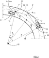
- FIG. 1 schematically shows a top view of an ego vehicle 1 arranged to run at an ego vehicle velocity v on a road 2 in a forward over-ground movement direction F, in the following referred to as ego direction F, where the ego vehicle 1 comprises a vehicle radar system 3.
- the vehicle radar system 3 comprises a radar sensor arrangement 4 that is arranged to distinguish and/or resolve single targets from the surroundings by transmitting signals 6 and receiving reflected signals 7 and using a Doppler effect in a previously well-known manner.
- the vehicle radar system 3 further comprises a main control unit 8 that is connected to the radar sensor arrangement 4 and is arranged to provide radial velocity and azimuth angles of possible target objects 5 by simultaneously sampling and analyzing phase and amplitude of the received signals 7.
- the reflected signals 7 correspond to radar detections, where the main control unit 8 comprises a tracking function that is arranged to group these radar detections as tracked objects, providing a common motion state for an extended detected object.
- the ego vehicle 1 has a center of mass 10 and an angular rotational velocity ⁇ ego . around the center of mass 10, and the radar sensor arrangements 4 has a certain relation to the center of mass 10.
- a yaw sensor device 20 is connected to the main control unit 8.
- the radar sensor arrangement is positioned in the origin of a corresponding coordinate system 11, and is positioned at a distance y sen along a y-axis of the coordinate system 11 from the center of mass 10, and at a distance x sen along an x-axis of the coordinate system 11 from the center of mass 10.
- the ego vehicle 1 runs in the ego direction F on the road 2, and the vehicle radar system 3 tracks a detected object in the form of an oncoming vehicle 9.
- v relx , v rely is the detected relative velocity of the oncoming vehicle 9
- v egoX is the movement of the radar sensor arrangement 4 resulting from the center of mass 10 of the ego vehicle 1
- y sen . ⁇ ego . , x sen ⁇ ⁇ ego . is the movement of the radar sensor arrangement 4 resulting from a rotational movement around the center of mass 10.
- the measured oncome direction 13 and the ego direction F' are shifted to correspond with that the vehicles 1, 9 are positioned on a common curve 12 with a certain curve radius R.
- the center of mass 10 of the ego vehicle 1 is shifted to an adjusted center of mass 10' and the oncoming vehicle 9 is shifted to an adjusted detected oncoming position 14' which both are positioned on the common curve 12. This does not affect the oncome angle ⁇ track .
- the main control unit 8 is arranged to determine whether the ego vehicle 1 travels in a curve 17 by detecting if the angular rotational velocity ⁇ ego . exceeds a certain threshold, according to some aspects 2 deg/s. If that is the case, the main control unit 8 is arranged to determine a calculated oncome direction 13' that the oncoming vehicle 9 would have if it is moving along the common curve 12. The calculated oncome direction 13' corresponds to a direction the ego vehicle 1 would follow when it had travelled to the position of the oncoming vehicle 9 along the common curve 12.
- the calculated oncome direction 13' has a certain calculated oncome angle ⁇ relative the ego direction F" in the position of the oncoming vehicle 9, and the calculated oncome angle ⁇ is thus the angle that the ego direction F would be shifted when the ego vehicle 1 has travelled to the position of the oncoming vehicle 9 along the common curve 12.
- the main control unit 8 is then arranged to calculate a difference angle ⁇ between the measured oncome direction 13 and the calculated oncome direction 13' such that it can be established how much the oncome direction 13 differ from the calculated oncome direction 13' that corresponds to if the oncoming vehicle is moving on the same common curve 12 as the ego vehicle 1.
- the difference angle ⁇ thus constitutes a difference between the oncome angle ⁇ track and the calculated oncome angle ⁇ . If the difference angle ⁇ exceeds a certain threshold angle ⁇ max , the oncoming vehicle 9 is determined to be crossing.
- the oncome angle ⁇ track equals the calculated oncome angle ⁇ , such that the difference angle ⁇ equals zero.
- both vehicles 1, 9 move in the common curve 12.
- the oncoming vehicle 9 In order to determine whether the oncoming vehicle 9 should be determined to be crossing or not, i.e. whether the difference angle ⁇ exceeds a threshold or not. If the oncoming vehicle 9 is determined to be crossing, suitable safety measure are taken; for example emergency braking, emergency steering and pushing vehicle occupants towards the middle of the ego vehicle 1, suitably by means of one or more airbags.
- the threshold angle ⁇ max is adaptive, such that in straight driving situations, a first threshold angle ⁇ max1 is used, and in curves a second threshold angle ⁇ max2 is used, where the second threshold angle ⁇ max2 exceeds the first threshold angle ⁇ max1 .
- the first threshold angle ⁇ max1 is about 35°
- the second threshold angle ⁇ max2 is about 45°.
- the main control unit 8 is arranged to determine whether the ego vehicle 1 travels in a curve or not by detecting if the angular rotational velocity ⁇ ego . exceeds a certain threshold ⁇ egomax . , according to some aspects 2 deg/s, as mentioned previously. According to some aspects, If ⁇ ego . ⁇ ⁇ egomax .
- the threshold angle ⁇ max is step-wise reduced to the first threshold angle ⁇ max1 .
- Each subsequent step-wise change is according to some aspects performed for each subsequent radar cycle.
- a radar cycle is one observation phase during which the vehicle radar system 3 is arranged to acquire data, process said data on several signal processing levels and to send out available results.
- This can be a fixed time interval, or it can be a dynamic time interval depending on environment conditions and processing load.
- the present disclosure also relates to a method for detecting oncoming vehicles relative an ego vehicle (1), where the method comprises:
- the method further comprises:
- the method comprises applying one or more safety measures.
- the vehicle radar system 3 is comprised in a vehicle environment detection system 40.
- the present disclosure is related to a vehicle environment detection system 40 arranged for any suitable environment detection technology, for example radar as in the examples above, but also Lidar (Light detection and ranging) and/or image detection are conceivable.
- the yaw sensor device 20 is comprised in the vehicle environment detection system 40.
- the vehicle environment detection system 40 generally comprises one or more environment detection sensor arrangements 4.
- the main control unit 8 comprises one or more control unit parts which according to some aspects are combined, adjacent or distributed. One or more of such control unit parts are according to some aspects comprised in the vehicle environment detection system 40.
- any suitable reference point on the ego vehicle 1 can be used and adjusted to lie on the common curve 12.
- the orientation of the coordinates and the coordinate system may have many suitable configurations, generally there is a predetermined axis with reference to which the ego direction F is determined.
- the present disclosure relates to a vehicle environment detection system 40 adapted to be mounted in an ego vehicle 1 and comprising at least one vehicle environment sensor arrangement 4 and a main control unit 8, where the vehicle environment detection system 40 is arranged to detect and track at least one oncoming vehicle 9, where the vehicle environment detection system 40 is arranged to determine whether the ego vehicle 1 has entered a curve 17.
- the main control unit 8 is arranged to:
- the main control unit 8 is arranged to apply one or more safety measures.
- the vehicle environment detection system 40 comprises a yaw sensor device 20 that is connected to the main control unit 8 and is arranged to enable the main control unit 8 to determine an ego direction F along which the ego vehicle 1 travels and to determine whether the ego vehicle 1 has entered a curve 17.
- said reference point 10' is an adjusted center of mass 10 of the ego vehicle 1, and that the angular rotational velocity ⁇ ego . is defined around said center of mass 10.
- the threshold angle ⁇ max is step-wise reduced to the first threshold angle ⁇ max1 .
- the vehicle environment detection system 40 comprises at least one of a radar system 3, a Lidar (Light detection and ranging) system and/or an image detection system.
- the present disclosure also relates to a method for detecting oncoming vehicles relative an ego vehicle 1, where the method comprises:
- the method further comprises:
- the method comprises applying one or more safety measures.
- the method comprises:
- said reference point 10' is an adjusted center of mass 10 of the ego vehicle 1, and that the angular rotational velocity ⁇ ego . is defined around said center of mass 10.
- the method comprises step-wise reducing the threshold angle ⁇ max to the first threshold angle ⁇ max1 .
Description
- The present disclosure relates to a vehicle environment detection system adapted to be mounted in an ego vehicle and comprising at least one vehicle environment sensor arrangement and a main control unit. The vehicle environment detection system is arranged to detect and track at least one oncoming vehicle.
- Today, vehicle environment detection systems, such as for example camera systems, Doppler radar systems and Lidar (Light detection and ranging) systems, can be mounted on a vehicle in order to detect objects in order to implement automated vehicle systems such as speed control and collision prevention.
- Radar systems are arranged to produce output comprising a series of reflection points as measured by radar sensors. These reflection points can be treated as separate detections or grouped as tracked objects, providing a common motion state for an extended object.
- There are previously known vehicle occupant safety systems which detect side-impacts before the actual crash. In the case that it has been determined that a crash is imminent, vehicle occupants can for example be pushed towards the middle of the car.
- To avoid false positives, a sensor used for this purpose has to robustly classify tracks as oncoming or crossing traffic, especially in curves.
-
US 8,847,792 discloses estimating the risk of an impact of an oncoming vehicle based on the movement amount of a radar reflection point on the oncoming vehicle when the reflection point varies in a vehicle width direction from the left front end toward the right front end of an oncoming vehicle. The acquired data is used for determination of the possibility of collision with an oncoming vehicle, on a curved road or the like. -
US 7885766 discloses a vehicle departure determination apparatus in a subject vehicle that determines whether the subject vehicle has departed from an appropriate route for the subject vehicle, or an oncoming vehicle has departed from an appropriate route for the oncoming vehicle. -
US 2011/175767 discloses a radar apparatus that calculates a time until an object and an own vehicle collide with each other, based on relative position and relative velocity of the object. Based on the calculated time, a filter coefficient, to be used when filter processing is performed on a measured position, is changed. -
US 2016/207534 discloses a collision avoidance control system that calculates an own vehicle course and an oncoming vehicle course. When it is determined that the own vehicle or oncoming vehicle is traveling on a curve, the travel courses of both vehicles are predicted via tracking/extrapolation. - It is, however, desired to provide a vehicle radar system that is adapted to classify tracks as oncoming or crossing traffic, especially in curves in an accurate, efficient and reliable manner, which also is an object of the present disclosure. In the case of oncoming traffic, it is determined whether an oncoming vehicle will collide with an ego vehicle.
- Said object is achieved by means of a vehicle environment detection system adapted to be mounted in an ego vehicle and comprising at least one vehicle environment sensor arrangement and a main control unit. The vehicle environment detection system is arranged to detect and track at least one oncoming vehicle, and to determine whether the ego vehicle has entered a curve. When the vehicle environment detection system has determined that the ego vehicle has entered a curve, for each tracked oncoming vehicle, the main control unit is arranged to perform the following:
- Determine a common curve with a radius along which common curve the ego vehicle is assumed to travel.
- Determine a measured oncome direction of said tracked oncoming vehicle on the common curve, corresponding to an oncome angle with respect to a predetermined axis.
- Determine a difference angle between said measured oncome direction and an oncome direction corresponding to if the oncoming vehicle would be moving along the common curve.
- Compare the difference angle with a threshold angle.
- Determine that the oncoming vehicle is crossing if the difference angle has been determined to exceed the threshold angle.
- Said object is also achieved by means of a method for detecting oncoming vehicles relative an ego vehicle. The method comprises: Detecting and tracking at least one oncoming vehicle and determining whether the ego vehicle has entered a curve.
- When it has been determined that the ego vehicle has entered a curve, for each tracked oncoming vehicle, the method further comprises determining a common curve with a radius, along which common curve the ego vehicle is assumed to travel, and determining a measured oncome direction of said tracked oncoming vehicle on the common curve, corresponding to an oncome angle with respect to a predetermined axis.
- The method then comprises determining a difference angle between said measured oncome direction and an oncome direction corresponding to if the oncoming vehicle would be moving along the common curve, comparing the difference angle with a threshold angle, and finally determining that the oncoming vehicle is crossing if the difference angle has been determined to exceed the threshold angle.
- A number of advantages are obtained by means of the present disclosure. Mainly, a vehicle radar system is provided that determines whether an oncoming vehicle will collide with an ego vehicle in a more accurate, efficient and reliable manner, than previously described.
- According to some aspects, for each tracked oncoming vehicle that has been determined to be crossing, one or more safety measures is/are applied.
- According to some aspects, the main control unit is arranged to calculate the difference angle according to δ = θtrack - α, where θtrack is said oncome angle and α is a calculated oncome angle corresponding to if the oncoming vehicle would be moving along the common curve. The main control unit is arranged to calculate the calculated oncome angle according to


- According to some aspects, when the vehicle environment detection system has determined that the ego vehicle has entered a curve, the main control unit is arranged to increase the threshold angle stepwise from a first threshold angle to a second threshold angle. This is performed in a in a step-wise manner according to:


- In this manner, the reliability of the vehicle environment detection system is increased.
- According to some aspects, when the vehicle environment detection system has determined that the ego vehicle has left said curve, the threshold angle is step-wise reduced to the first threshold angle.
- Other aspects of the present disclosure are disclosed in the dependent claims.
- The present disclosure will now be described more in detail with reference to the appended drawings, where:
- Figure 1
- shows a schematic top view of an ego vehicle;
- Figure 2
- shows a schematic top view of an ego vehicle and an oncoming vehicle according to a first example;
- Figure 3
- shows a schematic top view of an ego vehicle and an oncoming vehicle according to a second example; and
- Figure 4
- shows a flowchart for a method according to the present disclosure.
-
Figure 1 schematically shows a top view of anego vehicle 1 arranged to run at an ego vehicle velocity v on aroad 2 in a forward over-ground movement direction F, in the following referred to as ego direction F, where theego vehicle 1 comprises avehicle radar system 3. Thevehicle radar system 3 comprises a radar sensor arrangement 4 that is arranged to distinguish and/or resolve single targets from the surroundings by transmittingsignals 6 and receivingreflected signals 7 and using a Doppler effect in a previously well-known manner. Thevehicle radar system 3 further comprises amain control unit 8 that is connected to the radar sensor arrangement 4 and is arranged to provide radial velocity and azimuth angles ofpossible target objects 5 by simultaneously sampling and analyzing phase and amplitude of the receivedsignals 7. - The
reflected signals 7 correspond to radar detections, where themain control unit 8 comprises a tracking function that is arranged to group these radar detections as tracked objects, providing a common motion state for an extended detected object. - The
ego vehicle 1 has a center ofmass 10 and an angular rotational velocity
mass 10, and the radar sensor arrangements 4 has a certain relation to the center ofmass 10. In order to detect an ego direction angle γego, that corresponds to the ego direction F, and the corresponding rotational velocity
yaw sensor device 20 is connected to themain control unit 8. - The radar sensor arrangement is positioned in the origin of a
corresponding coordinate system 11, and is positioned at a distance ysen along a y-axis of thecoordinate system 11 from the center ofmass 10, and at a distance xsen along an x-axis of thecoordinate system 11 from the center ofmass 10. - With reference also to
Figure 2 , theego vehicle 1 runs in the ego direction F on theroad 2, and thevehicle radar system 3 tracks a detected object in the form of anoncoming vehicle 9. The tracking function is arranged to determine over-ground speed of theoncoming vehicle 9 in the form of perpendicular velocity components vxtrack, vytrack as:
oncoming vehicle 9, vegoX is the movement of the radar sensor arrangement 4 resulting from the center ofmass 10 of theego vehicle 1,

mass 10. - The oncoming
vehicle 9 has a detected oncomingposition 14 and a measuredoncome direction 13 according to an oncome angle θtrack with respect to the x-axis, which oncome angle θtrack is calculated as:
- In
Figure 2 , the measuredoncome direction 13 and the ego direction F' are shifted to correspond with that thevehicles common curve 12 with a certain curve radius R. The center ofmass 10 of theego vehicle 1 is shifted to an adjusted center of mass 10' and theoncoming vehicle 9 is shifted to an adjusted detected oncoming position 14' which both are positioned on thecommon curve 12. This does not affect the oncome angle θtrack. - According to the present disclosure, the
main control unit 8 is arranged to determine whether theego vehicle 1 travels in acurve 17 by detecting if the angular rotational velocity
aspects 2 deg/s. If that is the case, themain control unit 8 is arranged to determine a calculated oncome direction 13' that theoncoming vehicle 9 would have if it is moving along thecommon curve 12. The calculated oncome direction 13' corresponds to a direction theego vehicle 1 would follow when it had travelled to the position of theoncoming vehicle 9 along thecommon curve 12. - The calculated oncome direction 13' has a certain calculated oncome angle α relative the ego direction F" in the position of the
oncoming vehicle 9, and the calculated oncome angle α is thus the angle that the ego direction F would be shifted when theego vehicle 1 has travelled to the position of theoncoming vehicle 9 along thecommon curve 12. - The
main control unit 8 is then arranged to calculate a difference angle δ between the measuredoncome direction 13 and the calculated oncome direction 13' such that it can be established how much theoncome direction 13 differ from the calculated oncome direction 13' that corresponds to if the oncoming vehicle is moving on the samecommon curve 12 as theego vehicle 1. The difference angle δ thus constitutes a difference between the oncome angle θtrack and the calculated oncome angle α. If the difference angle δ exceeds a certain threshold angle θmax, the oncomingvehicle 9 is determined to be crossing. - With reference to
Figure 2 andFigure 3 , showing a first example and a second example, respectively, it will now be explained how the calculated oncome direction 13' and the calculated oncome angle α are determined. - For the calculated oncome direction 13' it is assumed that both
vehicles common curve 12. In order to obtain the calculated oncome angle α, a triangle between a common curve middle-point 15, the adjusted detected oncoming position 14', and the adjusted center of mass 10' is formed. This triangle is divided into two isosceles 90°-triangles. A distance D between the detected oncomingposition 14 and the adjusted center ofmass 10 is known and assumed to be the same as a distance between the adjusted detected oncoming position 14' and the adjusted center of mass 10'; a short side of one 90°-triangle is then D/2. - The common curve radius R is calculated by using the ego vehicle velocity v and the angular rotational velocity


- As a result,

- In
Figure 2 , the oncome angle θtrack equals the calculated oncome angle α, such that the difference angle δ equals zero. In this example, bothvehicles common curve 12. - In
Figure 3 , the oncome angle θ'track does not equal the calculated oncome angle α such that there is a certain difference angle δ = θ'track - α. - It is thus determined how much the actual measured moving direction of the
oncoming vehicle 9 differs from the moving direction corresponding to if theoncoming vehicle 9 would be moving along thecommon curve 12. - In order to determine whether the oncoming
vehicle 9 should be determined to be crossing or not, i.e. whether the difference angle δ exceeds a threshold or not. If theoncoming vehicle 9 is determined to be crossing, suitable safety measure are taken; for example emergency braking, emergency steering and pushing vehicle occupants towards the middle of theego vehicle 1, suitably by means of one or more airbags. - According to some aspects, the threshold angle θmax is adaptive, such that in straight driving situations, a first threshold angle θmax1 is used, and in curves a second threshold angle θmax2 is used, where the second threshold angle θmax2 exceeds the first threshold angle θmax1. According to some aspects, the first threshold angle θmax1 is about 35°, and the second threshold angle θmax2 is about 45°.
- For this purpose the
main control unit 8 is arranged to determine whether theego vehicle 1 travels in a curve or not by detecting if the angular rotational velocity

aspects 2 deg/s, as mentioned previously. According to some aspects, If
main control unit 8 is arranged to increase the threshold angle θmax stepwise from the first threshold angle θmax1 to the second threshold angle θmax2 in a step-wise manner according to:
- When the
main control unit 8 determines that
- Each subsequent step-wise change is according to some aspects performed for each subsequent radar cycle.
- In this context, a radar cycle is one observation phase during which the
vehicle radar system 3 is arranged to acquire data, process said data on several signal processing levels and to send out available results. This can be a fixed time interval, or it can be a dynamic time interval depending on environment conditions and processing load. - With reference to
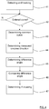
Figure 4 , the present disclosure also relates to a method for detecting oncoming vehicles relative an ego vehicle (1), where the method comprises: - 41: Detecting and tracking at least one
oncoming vehicle 9. - 42: Determining whether the
ego vehicle 1 has entered acurve 17. - When it has been determined that the
ego vehicle 1 has entered acurve 17, for each tracked oncomingvehicle 9, the method further comprises: - 43: Determining a
common curve 12 with a radius R, along whichcommon curve 12 theego vehicle 1 is assumed to travel. - 44: Determining a measured
oncome direction 13, 13' of said trackedoncoming vehicle 9 on the common curve 16, corresponding to an oncome angle θtrack with respect to a predetermined axis x. - 45: Determining a difference angle δ between said measured
oncome direction 13, 13' and anoncome direction 13 corresponding to if theoncoming vehicle 9 would be moving along thecommon curve 12. - 46: Comparing the difference angle δ with a threshold angle θmax.
- 47: Determining that the
oncoming vehicle 9 is crossing if the difference angle δ has been determined to exceed the threshold angle θmax. - According to some aspects, for each tracked oncoming
vehicle 9 that has been determined to be crossing, the method comprises applying one or more safety measures. - The present disclosure is not limited to the examples above, but may vary freely within the scope of the appended claims. For example, the
vehicle radar system 3 is comprised in a vehicle environment detection system 40. Generally, the present disclosure is related to a vehicle environment detection system 40 arranged for any suitable environment detection technology, for example radar as in the examples above, but also Lidar (Light detection and ranging) and/or image detection are conceivable. According to some aspects, when a yaw sensor device is present, theyaw sensor device 20 is comprised in the vehicle environment detection system 40. - The vehicle environment detection system 40 generally comprises one or more environment detection sensor arrangements 4.
- The
main control unit 8 comprises one or more control unit parts which according to some aspects are combined, adjacent or distributed. One or more of such control unit parts are according to some aspects comprised in the vehicle environment detection system 40. - Instead of center of mass, any suitable reference point on the
ego vehicle 1 can be used and adjusted to lie on thecommon curve 12. - The orientation of the coordinates and the coordinate system may have many suitable configurations, generally there is a predetermined axis with reference to which the ego direction F is determined.
- Generally, the present disclosure relates to a vehicle environment detection system 40 adapted to be mounted in an
ego vehicle 1 and comprising at least one vehicle environment sensor arrangement 4 and amain control unit 8, where the vehicle environment detection system 40 is arranged to detect and track at least oneoncoming vehicle 9, where the vehicle environment detection system 40 is arranged to determine whether theego vehicle 1 has entered acurve 17. When the vehicle environment detection system 40 has determined that theego vehicle 1 has entered acurve 17, for each tracked oncomingvehicle 9, themain control unit 8 is arranged to: - determine a
common curve 12 with a radius R, along whichcommon curve 12 theego vehicle 1 is assumed to travel; - determine a measured
oncome direction 13, 13' of said trackedoncoming vehicle 9 on the common curve 16, corresponding to an oncome angle θtrack with respect to a predetermined axis x; - determine a difference angle δ between said measured
oncome direction 13, 13' and anoncome direction 13 corresponding to if theoncoming vehicle 9 would be moving along thecommon curve 12; - compare the difference angle δ with a threshold angle θmax; and
- determine that the
oncoming vehicle 9 is crossing if the difference angle δ has been determined to exceed the threshold angle θmax. - According to some aspects, for each tracked oncoming
vehicle 9 that has been determined to be crossing, themain control unit 8 is arranged to apply one or more safety measures. - According to some aspects, the vehicle environment detection system 40 comprises a
yaw sensor device 20 that is connected to themain control unit 8 and is arranged to enable themain control unit 8 to determine an ego direction F along which theego vehicle 1 travels and to determine whether theego vehicle 1 has entered acurve 17. - According to some aspects, the
main control unit 8 is arranged to calculate the difference angle δ according to δ = θtrack - α, where θtrack is said oncome angle and α is a calculated oncome angle corresponding to if theoncoming vehicle 9 would be moving along thecommon curve 12, where themain control unit 8 is arranged to calculate the calculated oncome angle α according to
common curve 12,

- According to some aspects, said reference point 10' is an adjusted center of
mass 10 of theego vehicle 1, and that the angular rotational velocity
mass 10. - According to some aspects, when the vehicle environment detection system 40 has determined that the
ego vehicle 1 has entered acurve 17, themain control unit 8 is arranged to increase the threshold angle θmax stepwise from a first threshold angle θmax1 to a second threshold angle θmax2 in a step-wise manner according to:

ego vehicle 1, and where the second threshold angle θmax2 exceeds the first threshold angle θmax1. - According to some aspects, when the vehicle environment detection system 40 has determined that the
ego vehicle 1 has left saidcurve 17, the threshold angle θmax is step-wise reduced to the first threshold angle θmax1. - According to some aspects, the vehicle environment detection system 40 comprises at least one of a
radar system 3, a Lidar (Light detection and ranging) system and/or an image detection system. - Generally, the present disclosure also relates to a method for detecting oncoming vehicles relative an
ego vehicle 1, where the method comprises: - 41: detecting and tracking at least one
oncoming vehicle 9; and - 42: determining whether the
ego vehicle 1 has entered acurve 17. - When it has been determined that the
ego vehicle 1 has entered acurve 17, for each tracked oncomingvehicle 9, the method further comprises: - 43: determining a
common curve 12 with a radius R, along whichcommon curve 12 theego vehicle 1 is assumed to travel; - 44: determining a measured
oncome direction 13, 13' of said trackedoncoming vehicle 9 on the common curve 16, corresponding to an oncome angle θtrack with respect to a predetermined axis x; - 45: determining a difference angle δ between said measured
oncome direction 13, 13' and anoncome direction 13 corresponding to if theoncoming vehicle 9 would be moving along thecommon curve 12; - 46: comparing the difference angle δ with a threshold angle θmax; and
- 47: determining that the
oncoming vehicle 9 is crossing if the difference angle δ has been determined to exceed the threshold angle θmax. - According to some aspects, for each tracked oncoming
vehicle 9 that has been determined to be crossing, the method comprises applying one or more safety measures. - According to some aspects, the method comprises:
- calculating the difference angle δ according to δ = θtrack - α, where θtrack is said oncome angle and α is a calculated oncome angle corresponding to if the
oncoming vehicle 9 would be moving along thecommon curve 12; and - calculating the calculated oncome angle α according to

common curve 12,

- According to some aspects, said reference point 10' is an adjusted center of
mass 10 of theego vehicle 1, and that the angular rotational velocity
mass 10. - According to some aspects, when it has been determined that the
ego vehicle 1 has entered acurve 17, the method comprises increasing the threshold angle θmax stepwise from a first threshold angle θmax1 to a second threshold angle θmax2 in a step-wise manner according to:

ego vehicle 1, and where the second threshold angle θmax2 exceeds the first threshold angle θmax1. - According to some aspects, when it has been determined that the
ego vehicle 1 has left saidcurve 17, the method comprises step-wise reducing the threshold angle θmax to the first threshold angle θmax1.
Claims (14)
- A vehicle environment detection system (40) adapted to be mounted in an ego vehicle (1) and comprising at least one vehicle environment sensor arrangement (4) and a main control unit (8), where the vehicle environment detection system (40) is arranged to detect and track at least one oncoming vehicle (9), where the vehicle environment detection system (40) is arranged to determine whether the ego vehicle (1) has entered a curve (17), characterized in that when the vehicle environment detection system (40) has determined that the ego vehicle (1) has entered a curve (17), for each tracked oncoming vehicle (9), the main control unit (8) is arranged to:- determine a common curve (12) with a radius (R), along which common curve (12) the ego vehicle (1) is assumed to travel;- determine a measured oncome direction (13, 13') of said tracked oncoming vehicle (9) on the common curve (16), corresponding to an oncome angle (θtrack) with respect to a predetermined axis (x);- determine a difference angle (δ) between said measured oncome direction (13, 13') and an oncome direction (13) corresponding to if the oncoming vehicle (9) would be moving along the common curve (12);- compare the difference angle (δ) with a threshold angle θmax); and- determine that the oncoming vehicle (9) is crossing if the difference angle (δ) has been determined to exceed the threshold angle (θmax).
- The vehicle environment detection system (40) according to claim 1, characterized in that for each tracked oncoming vehicle (9) that has been determined to be crossing, the main control unit (8) is arranged to apply one or more safety measures.
- The vehicle environment detection system (40) according to any one of the claims 1 or 2, characterized in that the vehicle environment detection system (40) comprises a yaw sensor device (20) that is connected to the main control unit (8) and is arranged to enable the main control unit (8) to determine an ego direction (F) along which the ego vehicle (1) travels and to determine whether the ego vehicle (1) has entered a curve (17).
- The vehicle environment detection system (40) according to any one of the previous claims, characterized in that the main control unit (8) is arranged to calculate the difference angle (δ) according to δ = θtrack - α, where θtrack is said oncome angle and α is a calculated oncome angle corresponding to if the oncoming vehicle (9) would be moving along the common curve (12), where the main control unit (8) is arranged to calculate the calculated oncome angle (α) according to


- The vehicle environment detection system (40) according to claim 4, characterized in that said reference point (10') is an adjusted center of mass (10) of the ego vehicle (1), and that the angular rotational velocity

- The vehicle environment detection system (40) according to any one of the previous claims, characterized in that when the vehicle environment detection system (40) has determined that the ego vehicle (1) has entered a curve (17), the main control unit (8) is arranged to increase the threshold angle (θmax) stepwise from a first threshold angle (θmax1) to a second threshold angle (θmax2) in a step-wise manner according to:


- The vehicle environment detection system (40) according to claim 6, characterized in that when the vehicle environment detection system (40) has determined that the ego vehicle (1) has left said curve (17), the threshold angle (θmax) is step-wise reduced to the first threshold angle (θmax1).
- The vehicle environment detection system (40) according to any one of the previous claims, characterized in that the vehicle environment detection system (40) comprises at least one of a radar system (3), a Lidar, Light detection and ranging, system and/or an image detection system.
- A method for detecting oncoming vehicles relative an ego vehicle (1), where the method comprises:(41) detecting and tracking at least one oncoming vehicle (9) ; and(42) determining whether the ego vehicle (1) has entered a curve (17),characterized in that when it has been determined that the ego vehicle (1) has entered a curve (17), for each tracked oncoming vehicle (9), the method further comprises:(43) determining a common curve (12) with a radius (R), along which common curve (12) the ego vehicle (1) is assumed to travel;(44) determining a measured oncome direction (13, 13') of said tracked oncoming vehicle (9) on the common curve (16), corresponding to an oncome angle (θtrack) with respect to a predetermined axis (x);(45) determining a difference angle (δ) between said measured oncome direction (13, 13') and an oncome direction (13) corresponding to if the oncoming vehicle (9) would be moving along the common curve (12);(46) comparing the difference angle (δ) with a threshold angle (θmax); and(47) determining that the oncoming vehicle (9) is crossing if the difference angle (δ) has been determined to exceed the threshold angle (θmax).
- The method according to claim 9, characterized in that for each tracked oncoming vehicle (9) that has been determined to be crossing, the method comprises applying one or more safety measures.
- The method according to any one of the claims 9 or 10, characterized in that the method comprises:calculating the difference angle (δ) according to δ = θtrack - α, where θtrack is said oncome angle and α is a calculated oncome angle corresponding to if the oncoming vehicle (9) would be moving along the common curve (12); andcalculating the calculated oncome angle (α) according to


- The method according to claim 11, characterized in that said reference point (10') is an adjusted center of mass (10) of the ego vehicle (1), and that the angular rotational velocity

- The method according to any one of the claims 9-12, characterized in that when it has been determined that the ego vehicle (1) has entered a curve (17), the method comprises increasing the threshold angle (θmax) stepwise from a first threshold angle (θmax1) to a second threshold angle (θmax2) in a step-wise manner according to:


- The method according to claim 13, characterized in that when it has been determined that the ego vehicle (1) has left said curve (17), the method comprises step-wise reducing the threshold angle (θmax) to the first threshold angle (θmax1).
Priority Applications (5)
| Application Number | Priority Date | Filing Date | Title |
|---|---|---|---|
| EP17175128.2A EP3413082B1 (en) | 2017-06-09 | 2017-06-09 | A vehicle system for detection of oncoming vehicles |
| PCT/EP2018/064762 WO2018224495A1 (en) | 2017-06-09 | 2018-06-05 | A vehicle system for detection of oncoming vehicles |
| US16/620,051 US11433900B2 (en) | 2017-06-09 | 2018-06-05 | Vehicle system for detection of oncoming vehicles |
| CN201880034793.5A CN110678778B (en) | 2017-06-09 | 2018-06-05 | Vehicle system for detecting an oncoming vehicle |
| US17/861,632 US20220348209A1 (en) | 2017-06-09 | 2022-07-11 | Vehicle system for detection of oncoming vehicles |
Applications Claiming Priority (1)
| Application Number | Priority Date | Filing Date | Title |
|---|---|---|---|
| EP17175128.2A EP3413082B1 (en) | 2017-06-09 | 2017-06-09 | A vehicle system for detection of oncoming vehicles |
Publications (2)
| Publication Number | Publication Date |
|---|---|
| EP3413082A1 EP3413082A1 (en) | 2018-12-12 |
| EP3413082B1 true EP3413082B1 (en) | 2020-01-01 |
Family
ID=59034554
Family Applications (1)
| Application Number | Title | Priority Date | Filing Date |
|---|---|---|---|
| EP17175128.2A Active EP3413082B1 (en) | 2017-06-09 | 2017-06-09 | A vehicle system for detection of oncoming vehicles |
Country Status (4)
| Country | Link |
|---|---|
| US (2) | US11433900B2 (en) |
| EP (1) | EP3413082B1 (en) |
| CN (1) | CN110678778B (en) |
| WO (1) | WO2018224495A1 (en) |
Families Citing this family (2)
| Publication number | Priority date | Publication date | Assignee | Title |
|---|---|---|---|---|
| EP3413083B1 (en) * | 2017-06-09 | 2020-03-11 | Veoneer Sweden AB | A vehicle system for detection of oncoming vehicles |
| EP3413082B1 (en) * | 2017-06-09 | 2020-01-01 | Veoneer Sweden AB | A vehicle system for detection of oncoming vehicles |
Family Cites Families (57)
| Publication number | Priority date | Publication date | Assignee | Title |
|---|---|---|---|---|
| US6822563B2 (en) * | 1997-09-22 | 2004-11-23 | Donnelly Corporation | Vehicle imaging system with accessory control |
| DE19736965C1 (en) * | 1997-08-25 | 1999-05-06 | Mannesmann Vdo Ag | Method and arrangement for checking the yaw rate of a moving object |
| JP3658519B2 (en) * | 1999-06-28 | 2005-06-08 | 株式会社日立製作所 | Vehicle control system and vehicle control device |
| US7522091B2 (en) * | 2002-07-15 | 2009-04-21 | Automotive Systems Laboratory, Inc. | Road curvature estimation system |
| DE10254423A1 (en) * | 2002-11-21 | 2004-06-03 | Lucas Automotive Gmbh | System for influencing the speed of a motor vehicle |
| JP4421450B2 (en) * | 2004-11-22 | 2010-02-24 | 本田技研工業株式会社 | Vehicle departure determination device |
| JP2006267005A (en) * | 2005-03-25 | 2006-10-05 | Xanavi Informatics Corp | Current position calculation device, and positional information calculation method |
| JP4169065B2 (en) * | 2006-02-13 | 2008-10-22 | 株式会社デンソー | Vehicle control device |
| DE602006015362D1 (en) * | 2006-03-06 | 2010-08-19 | Hitachi Ltd | CONTROL DEVICE AND METHOD FOR AUTOMOBILES |
| JP5038986B2 (en) * | 2008-07-04 | 2012-10-03 | トヨタ自動車株式会社 | Collision prediction device |
| JP5212753B2 (en) * | 2008-12-22 | 2013-06-19 | トヨタ自動車株式会社 | Radar apparatus and measurement method used in the radar apparatus |
| JP5310674B2 (en) * | 2010-08-17 | 2013-10-09 | 株式会社デンソー | Vehicle behavior control device |
| WO2012039012A1 (en) | 2010-09-24 | 2012-03-29 | トヨタ自動車株式会社 | Object detector and object detecting program |
| US9415718B2 (en) * | 2011-06-08 | 2016-08-16 | Denso Corporation | Vehicular headlight apparatus |
| CN103765487B (en) * | 2011-08-26 | 2016-03-30 | 丰田自动车株式会社 | Drive assistance device and driving assistance method |
| JP5760884B2 (en) * | 2011-09-09 | 2015-08-12 | 株式会社デンソー | Vehicle turning prediction device |
| US9321329B2 (en) * | 2012-05-10 | 2016-04-26 | Chris Beckman | Glare elimination and image enhancement system improving lenses, windows and displays |
| WO2014016910A1 (en) * | 2012-07-24 | 2014-01-30 | トヨタ自動車株式会社 | Drive assist device |
| JP6183799B2 (en) * | 2013-06-14 | 2017-08-23 | 日立オートモティブシステムズ株式会社 | Vehicle control system |
| DE102013211651A1 (en) * | 2013-06-20 | 2014-12-24 | Robert Bosch Gmbh | Method and device for avoiding a possible subsequent collision or for reducing the accident consequences of a collision |
| CN105377629B (en) * | 2013-07-11 | 2018-11-02 | 株式会社小糸制作所 | The light distribution control method and light distribution control of headlight for automobile |
| JP2015033944A (en) * | 2013-08-09 | 2015-02-19 | スタンレー電気株式会社 | Lighting control device for headlight of vehicle, and headlight system of vehicle |
| US9738222B2 (en) * | 2013-09-28 | 2017-08-22 | Oldcastle Materials, Inc. | Advanced warning and risk evasion system and method |
| WO2015057147A1 (en) * | 2013-10-16 | 2015-04-23 | Sentient Sweden Ekonomisk Förening | Method in order to control vehicle behaviour |
| US9988047B2 (en) * | 2013-12-12 | 2018-06-05 | Magna Electronics Inc. | Vehicle control system with traffic driving control |
| WO2015155874A1 (en) * | 2014-04-10 | 2015-10-15 | 三菱電機株式会社 | Route prediction device |
| JP5969534B2 (en) * | 2014-04-21 | 2016-08-17 | 株式会社デンソー | Driving support device |
| JP2016001464A (en) * | 2014-05-19 | 2016-01-07 | 株式会社リコー | Processor, processing system, processing program, and processing method |
| JP2016001170A (en) * | 2014-05-19 | 2016-01-07 | 株式会社リコー | Processing unit, processing program and processing method |
| EP3183688B1 (en) * | 2014-08-18 | 2023-08-23 | Mobileye Vision Technologies Ltd. | Recognition and prediction of lane constraints |
| US9482751B2 (en) * | 2014-10-13 | 2016-11-01 | Applied Concepts, Inc. | Collision detection system and method of operation |
| JP5880904B1 (en) * | 2014-11-20 | 2016-03-09 | パナソニックIpマネジメント株式会社 | Terminal device |
| JP6246392B2 (en) * | 2014-12-09 | 2017-12-13 | 三菱電機株式会社 | Collision risk calculation device, collision risk display device, vehicle body control device |
| JP5979259B2 (en) * | 2015-01-20 | 2016-08-24 | トヨタ自動車株式会社 | Collision avoidance control device |
| JP6376348B2 (en) * | 2015-02-20 | 2018-08-22 | ウシオ電機株式会社 | Vehicle driving support device |
| WO2016183074A1 (en) * | 2015-05-10 | 2016-11-17 | Mobileye Vision Technologies Ltd. | Road profile along a predicted path |
| GB2541354A (en) * | 2015-05-27 | 2017-02-22 | Cambridge Entpr Ltd | Collision avoidance method, computer program product for said collision avoidance method and collision avoidance system |
| EP3106836B1 (en) * | 2015-06-16 | 2018-06-06 | Volvo Car Corporation | A unit and method for adjusting a road boundary |
| US10214206B2 (en) * | 2015-07-13 | 2019-02-26 | Magna Electronics Inc. | Parking assist system for vehicle |
| US9751506B2 (en) * | 2015-10-27 | 2017-09-05 | GM Global Technology Operations LLC | Algorithms for avoiding automotive crashes at left and right turn intersections |
| US9688273B2 (en) * | 2015-10-27 | 2017-06-27 | GM Global Technology Operations LLC | Methods of improving performance of automotive intersection turn assist features |
| JP6473685B2 (en) * | 2015-11-19 | 2019-02-20 | 日立建機株式会社 | Vehicle control device and work machine |
| DE102015224171A1 (en) * | 2015-12-03 | 2017-06-08 | Robert Bosch Gmbh | Tilt detection on two-wheeled vehicles |
| CN106355890B (en) * | 2016-09-27 | 2019-03-05 | 东软集团股份有限公司 | The judgment method and device of a kind of pair of target vehicle classification |
| US10416304B2 (en) * | 2017-03-06 | 2019-09-17 | The Aerospace Corporation | Automobile accident mitigation technique |
| EP3413082B1 (en) * | 2017-06-09 | 2020-01-01 | Veoneer Sweden AB | A vehicle system for detection of oncoming vehicles |
| EP3413083B1 (en) * | 2017-06-09 | 2020-03-11 | Veoneer Sweden AB | A vehicle system for detection of oncoming vehicles |
| DE102018210280A1 (en) * | 2018-06-25 | 2020-01-02 | Robert Bosch Gmbh | Adaptation of the trajectory of an ego vehicle to moving foreign objects |
| ES2963510T3 (en) * | 2018-09-18 | 2024-03-27 | Volvo Car Corp | Collision avoidance method and system |
| DE102019202592A1 (en) * | 2019-02-26 | 2020-08-27 | Volkswagen Aktiengesellschaft | Method for operating a driver information system in an ego vehicle and driver information system |
| DE102019202591A1 (en) * | 2019-02-26 | 2020-08-27 | Volkswagen Aktiengesellschaft | Method for operating a driver information system in an ego vehicle and driver information system |
| DE102019215147A1 (en) * | 2019-10-01 | 2021-04-01 | Continental Automotive Gmbh | Method and driver assistance device for driving an ego vehicle |
| US11635763B2 (en) * | 2020-02-28 | 2023-04-25 | Nissan North America, Inc. | 3D occlusion reasoning for accident avoidance |
| FR3120040B1 (en) * | 2021-02-19 | 2023-02-24 | Renault Sas | Method for activating an obstacle avoidance system for a motor vehicle |
| FR3120039A1 (en) * | 2021-02-19 | 2022-08-26 | Renault S.A.S | Obstacle avoidance method |
| US20220283587A1 (en) * | 2021-03-02 | 2022-09-08 | Motional Ad Llc | Controlling an autonomous vehicle using a proximity rule |
| US11614537B2 (en) * | 2021-04-01 | 2023-03-28 | GM Cruise Holdings LLC. | Radar system for generating an on-demand distributed aperture by mechanical articulation |
-
2017
- 2017-06-09 EP EP17175128.2A patent/EP3413082B1/en active Active
-
2018
- 2018-06-05 CN CN201880034793.5A patent/CN110678778B/en active Active
- 2018-06-05 US US16/620,051 patent/US11433900B2/en active Active
- 2018-06-05 WO PCT/EP2018/064762 patent/WO2018224495A1/en active Application Filing
-
2022
- 2022-07-11 US US17/861,632 patent/US20220348209A1/en active Pending
Non-Patent Citations (1)
| Title |
|---|
| None * |
Also Published As
| Publication number | Publication date |
|---|---|
| CN110678778B (en) | 2023-05-19 |
| US20200198640A1 (en) | 2020-06-25 |
| CN110678778A (en) | 2020-01-10 |
| WO2018224495A1 (en) | 2018-12-13 |
| EP3413082A1 (en) | 2018-12-12 |
| US11433900B2 (en) | 2022-09-06 |
| US20220348209A1 (en) | 2022-11-03 |
Similar Documents
| Publication | Publication Date | Title |
|---|---|---|
| US8112223B2 (en) | Method for measuring lateral movements in a driver assistance system | |
| US9886858B2 (en) | Lane change detection | |
| JP3658519B2 (en) | Vehicle control system and vehicle control device | |
| US11046312B2 (en) | Vehicle travel support device | |
| US20220348209A1 (en) | Vehicle system for detection of oncoming vehicles | |
| US20170326981A1 (en) | Vehicle cruise control apparatus and vehicle cruise control method | |
| EP3539837B1 (en) | A vehicle radar system for detecting preceding vehicles | |
| JP7028982B2 (en) | Radar processing device | |
| CN101578533B (en) | Surroundings monitoring apparatus for vehicle | |
| US20180118146A1 (en) | Object detecting apparatus and object detecting method | |
| US11307300B2 (en) | Vehicle radar system | |
| JP2002175599A (en) | Lane position estimating device for precedent vehicle or target | |
| US20050004719A1 (en) | Device and method for determining the position of objects in the surroundings of a motor vehicle | |
| EP3413083B1 (en) | A vehicle system for detection of oncoming vehicles | |
| JP3719691B2 (en) | Vehicle recognition device | |
| JP5178652B2 (en) | Vehicle travel safety device | |
| EP3293545A1 (en) | Determining relative velocity in a vehicle radar system | |
| Jansson et al. | A probabilistic approach to collision risk estimation for passenger vehicles |
Legal Events
| Date | Code | Title | Description |
|---|---|---|---|
| PUAI | Public reference made under article 153(3) epc to a published international application that has entered the european phase |
Free format text: ORIGINAL CODE: 0009012 |
|
| STAA | Information on the status of an ep patent application or granted ep patent |
Free format text: STATUS: THE APPLICATION HAS BEEN PUBLISHED |
|
| AK | Designated contracting states |
Kind code of ref document: A1 Designated state(s): AL AT BE BG CH CY CZ DE DK EE ES FI FR GB GR HR HU IE IS IT LI LT LU LV MC MK MT NL NO PL PT RO RS SE SI SK SM TR |
|
| AX | Request for extension of the european patent |
Extension state: BA ME |
|
| STAA | Information on the status of an ep patent application or granted ep patent |
Free format text: STATUS: REQUEST FOR EXAMINATION WAS MADE |
|
| 17P | Request for examination filed |
Effective date: 20190611 |
|
| RBV | Designated contracting states (corrected) |
Designated state(s): AL AT BE BG CH CY CZ DE DK EE ES FI FR GB GR HR HU IE IS IT LI LT LU LV MC MK MT NL NO PL PT RO RS SE SI SK SM TR |
|
| GRAP | Despatch of communication of intention to grant a patent |
Free format text: ORIGINAL CODE: EPIDOSNIGR1 |
|
| STAA | Information on the status of an ep patent application or granted ep patent |
Free format text: STATUS: GRANT OF PATENT IS INTENDED |
|
| RIC1 | Information provided on ipc code assigned before grant |
Ipc: G01S 13/93 20060101AFI20190701BHEP Ipc: G01S 17/93 20060101ALN20190701BHEP Ipc: B60W 30/095 20120101ALI20190701BHEP |
|
| INTG | Intention to grant announced |
Effective date: 20190729 |
|
| GRAS | Grant fee paid |
Free format text: ORIGINAL CODE: EPIDOSNIGR3 |
|
| GRAA | (expected) grant |
Free format text: ORIGINAL CODE: 0009210 |
|
| STAA | Information on the status of an ep patent application or granted ep patent |
Free format text: STATUS: THE PATENT HAS BEEN GRANTED |
|
| AK | Designated contracting states |
Kind code of ref document: B1 Designated state(s): AL AT BE BG CH CY CZ DE DK EE ES FI FR GB GR HR HU IE IS IT LI LT LU LV MC MK MT NL NO PL PT RO RS SE SI SK SM TR |
|
| REG | Reference to a national code |
Ref country code: GB Ref legal event code: FG4D |
|
| REG | Reference to a national code |
Ref country code: CH Ref legal event code: EP Ref country code: AT Ref legal event code: REF Ref document number: 1220471 Country of ref document: AT Kind code of ref document: T Effective date: 20200115 |
|
| REG | Reference to a national code |
Ref country code: IE Ref legal event code: FG4D |
|
| REG | Reference to a national code |
Ref country code: DE Ref legal event code: R096 Ref document number: 602017010278 Country of ref document: DE |
|
| REG | Reference to a national code |
Ref country code: NL Ref legal event code: MP Effective date: 20200101 |
|
| REG | Reference to a national code |
Ref country code: LT Ref legal event code: MG4D |
|
| PG25 | Lapsed in a contracting state [announced via postgrant information from national office to epo] |
Ref country code: FI Free format text: LAPSE BECAUSE OF FAILURE TO SUBMIT A TRANSLATION OF THE DESCRIPTION OR TO PAY THE FEE WITHIN THE PRESCRIBED TIME-LIMIT Effective date: 20200101 Ref country code: NO Free format text: LAPSE BECAUSE OF FAILURE TO SUBMIT A TRANSLATION OF THE DESCRIPTION OR TO PAY THE FEE WITHIN THE PRESCRIBED TIME-LIMIT Effective date: 20200401 Ref country code: PT Free format text: LAPSE BECAUSE OF FAILURE TO SUBMIT A TRANSLATION OF THE DESCRIPTION OR TO PAY THE FEE WITHIN THE PRESCRIBED TIME-LIMIT Effective date: 20200527 Ref country code: CZ Free format text: LAPSE BECAUSE OF FAILURE TO SUBMIT A TRANSLATION OF THE DESCRIPTION OR TO PAY THE FEE WITHIN THE PRESCRIBED TIME-LIMIT Effective date: 20200101 Ref country code: LT Free format text: LAPSE BECAUSE OF FAILURE TO SUBMIT A TRANSLATION OF THE DESCRIPTION OR TO PAY THE FEE WITHIN THE PRESCRIBED TIME-LIMIT Effective date: 20200101 Ref country code: NL Free format text: LAPSE BECAUSE OF FAILURE TO SUBMIT A TRANSLATION OF THE DESCRIPTION OR TO PAY THE FEE WITHIN THE PRESCRIBED TIME-LIMIT Effective date: 20200101 Ref country code: RS Free format text: LAPSE BECAUSE OF FAILURE TO SUBMIT A TRANSLATION OF THE DESCRIPTION OR TO PAY THE FEE WITHIN THE PRESCRIBED TIME-LIMIT Effective date: 20200101 |
|
| PG25 | Lapsed in a contracting state [announced via postgrant information from national office to epo] |
Ref country code: BG Free format text: LAPSE BECAUSE OF FAILURE TO SUBMIT A TRANSLATION OF THE DESCRIPTION OR TO PAY THE FEE WITHIN THE PRESCRIBED TIME-LIMIT Effective date: 20200401 Ref country code: IS Free format text: LAPSE BECAUSE OF FAILURE TO SUBMIT A TRANSLATION OF THE DESCRIPTION OR TO PAY THE FEE WITHIN THE PRESCRIBED TIME-LIMIT Effective date: 20200501 Ref country code: LV Free format text: LAPSE BECAUSE OF FAILURE TO SUBMIT A TRANSLATION OF THE DESCRIPTION OR TO PAY THE FEE WITHIN THE PRESCRIBED TIME-LIMIT Effective date: 20200101 Ref country code: SE Free format text: LAPSE BECAUSE OF FAILURE TO SUBMIT A TRANSLATION OF THE DESCRIPTION OR TO PAY THE FEE WITHIN THE PRESCRIBED TIME-LIMIT Effective date: 20200101 Ref country code: GR Free format text: LAPSE BECAUSE OF FAILURE TO SUBMIT A TRANSLATION OF THE DESCRIPTION OR TO PAY THE FEE WITHIN THE PRESCRIBED TIME-LIMIT Effective date: 20200402 Ref country code: HR Free format text: LAPSE BECAUSE OF FAILURE TO SUBMIT A TRANSLATION OF THE DESCRIPTION OR TO PAY THE FEE WITHIN THE PRESCRIBED TIME-LIMIT Effective date: 20200101 |
|
| REG | Reference to a national code |
Ref country code: DE Ref legal event code: R097 Ref document number: 602017010278 Country of ref document: DE |
|
| PG25 | Lapsed in a contracting state [announced via postgrant information from national office to epo] |
Ref country code: RO Free format text: LAPSE BECAUSE OF FAILURE TO SUBMIT A TRANSLATION OF THE DESCRIPTION OR TO PAY THE FEE WITHIN THE PRESCRIBED TIME-LIMIT Effective date: 20200101 Ref country code: ES Free format text: LAPSE BECAUSE OF FAILURE TO SUBMIT A TRANSLATION OF THE DESCRIPTION OR TO PAY THE FEE WITHIN THE PRESCRIBED TIME-LIMIT Effective date: 20200101 Ref country code: SM Free format text: LAPSE BECAUSE OF FAILURE TO SUBMIT A TRANSLATION OF THE DESCRIPTION OR TO PAY THE FEE WITHIN THE PRESCRIBED TIME-LIMIT Effective date: 20200101 Ref country code: EE Free format text: LAPSE BECAUSE OF FAILURE TO SUBMIT A TRANSLATION OF THE DESCRIPTION OR TO PAY THE FEE WITHIN THE PRESCRIBED TIME-LIMIT Effective date: 20200101 Ref country code: SK Free format text: LAPSE BECAUSE OF FAILURE TO SUBMIT A TRANSLATION OF THE DESCRIPTION OR TO PAY THE FEE WITHIN THE PRESCRIBED TIME-LIMIT Effective date: 20200101 Ref country code: DK Free format text: LAPSE BECAUSE OF FAILURE TO SUBMIT A TRANSLATION OF THE DESCRIPTION OR TO PAY THE FEE WITHIN THE PRESCRIBED TIME-LIMIT Effective date: 20200101 |
|
| PLBE | No opposition filed within time limit |
Free format text: ORIGINAL CODE: 0009261 |
|
| STAA | Information on the status of an ep patent application or granted ep patent |
Free format text: STATUS: NO OPPOSITION FILED WITHIN TIME LIMIT |
|
| REG | Reference to a national code |
Ref country code: AT Ref legal event code: MK05 Ref document number: 1220471 Country of ref document: AT Kind code of ref document: T Effective date: 20200101 |
|
| 26N | No opposition filed |
Effective date: 20201002 |
|
| PG25 | Lapsed in a contracting state [announced via postgrant information from national office to epo] |
Ref country code: MC Free format text: LAPSE BECAUSE OF FAILURE TO SUBMIT A TRANSLATION OF THE DESCRIPTION OR TO PAY THE FEE WITHIN THE PRESCRIBED TIME-LIMIT Effective date: 20200101 Ref country code: IT Free format text: LAPSE BECAUSE OF FAILURE TO SUBMIT A TRANSLATION OF THE DESCRIPTION OR TO PAY THE FEE WITHIN THE PRESCRIBED TIME-LIMIT Effective date: 20200101 Ref country code: AT Free format text: LAPSE BECAUSE OF FAILURE TO SUBMIT A TRANSLATION OF THE DESCRIPTION OR TO PAY THE FEE WITHIN THE PRESCRIBED TIME-LIMIT Effective date: 20200101 |
|
| REG | Reference to a national code |
Ref country code: CH Ref legal event code: PL |
|
| PG25 | Lapsed in a contracting state [announced via postgrant information from national office to epo] |
Ref country code: PL Free format text: LAPSE BECAUSE OF FAILURE TO SUBMIT A TRANSLATION OF THE DESCRIPTION OR TO PAY THE FEE WITHIN THE PRESCRIBED TIME-LIMIT Effective date: 20200101 Ref country code: SI Free format text: LAPSE BECAUSE OF FAILURE TO SUBMIT A TRANSLATION OF THE DESCRIPTION OR TO PAY THE FEE WITHIN THE PRESCRIBED TIME-LIMIT Effective date: 20200101 |
|
| PG25 | Lapsed in a contracting state [announced via postgrant information from national office to epo] |
Ref country code: LU Free format text: LAPSE BECAUSE OF NON-PAYMENT OF DUE FEES Effective date: 20200609 |
|
| REG | Reference to a national code |
Ref country code: BE Ref legal event code: MM Effective date: 20200630 |
|
| PG25 | Lapsed in a contracting state [announced via postgrant information from national office to epo] |
Ref country code: LI Free format text: LAPSE BECAUSE OF NON-PAYMENT OF DUE FEES Effective date: 20200630 Ref country code: CH Free format text: LAPSE BECAUSE OF NON-PAYMENT OF DUE FEES Effective date: 20200630 Ref country code: IE Free format text: LAPSE BECAUSE OF NON-PAYMENT OF DUE FEES Effective date: 20200609 |
|
| PG25 | Lapsed in a contracting state [announced via postgrant information from national office to epo] |
Ref country code: BE Free format text: LAPSE BECAUSE OF NON-PAYMENT OF DUE FEES Effective date: 20200630 |
|
| PG25 | Lapsed in a contracting state [announced via postgrant information from national office to epo] |
Ref country code: TR Free format text: LAPSE BECAUSE OF FAILURE TO SUBMIT A TRANSLATION OF THE DESCRIPTION OR TO PAY THE FEE WITHIN THE PRESCRIBED TIME-LIMIT Effective date: 20200101 Ref country code: MT Free format text: LAPSE BECAUSE OF FAILURE TO SUBMIT A TRANSLATION OF THE DESCRIPTION OR TO PAY THE FEE WITHIN THE PRESCRIBED TIME-LIMIT Effective date: 20200101 Ref country code: CY Free format text: LAPSE BECAUSE OF FAILURE TO SUBMIT A TRANSLATION OF THE DESCRIPTION OR TO PAY THE FEE WITHIN THE PRESCRIBED TIME-LIMIT Effective date: 20200101 |
|
| PG25 | Lapsed in a contracting state [announced via postgrant information from national office to epo] |
Ref country code: MK Free format text: LAPSE BECAUSE OF FAILURE TO SUBMIT A TRANSLATION OF THE DESCRIPTION OR TO PAY THE FEE WITHIN THE PRESCRIBED TIME-LIMIT Effective date: 20200101 Ref country code: AL Free format text: LAPSE BECAUSE OF FAILURE TO SUBMIT A TRANSLATION OF THE DESCRIPTION OR TO PAY THE FEE WITHIN THE PRESCRIBED TIME-LIMIT Effective date: 20200101 |
|
| REG | Reference to a national code |
Ref country code: DE Ref legal event code: R081 Ref document number: 602017010278 Country of ref document: DE Owner name: ARRIVER SOFTWARE AB, SE Free format text: FORMER OWNER: VEONEER SWEDEN AB, VARGARDA, SE |
|
| PGFP | Annual fee paid to national office [announced via postgrant information from national office to epo] |
Ref country code: FR Payment date: 20230509 Year of fee payment: 7 Ref country code: DE Payment date: 20230509 Year of fee payment: 7 |
|
| PGFP | Annual fee paid to national office [announced via postgrant information from national office to epo] |
Ref country code: GB Payment date: 20230510 Year of fee payment: 7 |