JP3800007B2 - Braking control device - Google Patents
Braking control device Download PDFInfo
- Publication number
- JP3800007B2 JP3800007B2 JP2001001930A JP2001001930A JP3800007B2 JP 3800007 B2 JP3800007 B2 JP 3800007B2 JP 2001001930 A JP2001001930 A JP 2001001930A JP 2001001930 A JP2001001930 A JP 2001001930A JP 3800007 B2 JP3800007 B2 JP 3800007B2
- Authority
- JP
- Japan
- Prior art keywords
- braking
- relative distance
- driver
- relative
- detecting
- Prior art date
- Legal status (The legal status is an assumption and is not a legal conclusion. Google has not performed a legal analysis and makes no representation as to the accuracy of the status listed.)
- Expired - Lifetime
Links
- 238000001514 detection method Methods 0.000 claims description 15
- 238000000034 method Methods 0.000 description 65
- 238000010586 diagram Methods 0.000 description 12
- 239000012530 fluid Substances 0.000 description 12
- 238000012545 processing Methods 0.000 description 12
- 230000007423 decrease Effects 0.000 description 10
- 238000004891 communication Methods 0.000 description 4
- 230000001133 acceleration Effects 0.000 description 3
- 238000013459 approach Methods 0.000 description 3
- 238000012937 correction Methods 0.000 description 2
- 230000003247 decreasing effect Effects 0.000 description 2
- 230000000694 effects Effects 0.000 description 2
- 230000004044 response Effects 0.000 description 2
- 101100075995 Schizosaccharomyces pombe (strain 972 / ATCC 24843) fma2 gene Proteins 0.000 description 1
- 230000005540 biological transmission Effects 0.000 description 1
- 230000000994 depressogenic effect Effects 0.000 description 1
- 238000005516 engineering process Methods 0.000 description 1
- 230000002093 peripheral effect Effects 0.000 description 1
- 230000001629 suppression Effects 0.000 description 1
- 230000002123 temporal effect Effects 0.000 description 1
Images


Classifications
-
- B—PERFORMING OPERATIONS; TRANSPORTING
- B60—VEHICLES IN GENERAL
- B60T—VEHICLE BRAKE CONTROL SYSTEMS OR PARTS THEREOF; BRAKE CONTROL SYSTEMS OR PARTS THEREOF, IN GENERAL; ARRANGEMENT OF BRAKING ELEMENTS ON VEHICLES IN GENERAL; PORTABLE DEVICES FOR PREVENTING UNWANTED MOVEMENT OF VEHICLES; VEHICLE MODIFICATIONS TO FACILITATE COOLING OF BRAKES
- B60T7/00—Brake-action initiating means
- B60T7/12—Brake-action initiating means for automatic initiation; for initiation not subject to will of driver or passenger
- B60T7/22—Brake-action initiating means for automatic initiation; for initiation not subject to will of driver or passenger initiated by contact of vehicle, e.g. bumper, with an external object, e.g. another vehicle, or by means of contactless obstacle detectors mounted on the vehicle
-
- B—PERFORMING OPERATIONS; TRANSPORTING
- B60—VEHICLES IN GENERAL
- B60G—VEHICLE SUSPENSION ARRANGEMENTS
- B60G2400/00—Indexing codes relating to detected, measured or calculated conditions or factors
- B60G2400/80—Exterior conditions
- B60G2400/82—Ground surface
- B60G2400/823—Obstacle sensing
-
- B—PERFORMING OPERATIONS; TRANSPORTING
- B60—VEHICLES IN GENERAL
- B60G—VEHICLE SUSPENSION ARRANGEMENTS
- B60G2400/00—Indexing codes relating to detected, measured or calculated conditions or factors
- B60G2400/80—Exterior conditions
- B60G2400/82—Ground surface
- B60G2400/824—Travel path sensing; Track monitoring
-
- B—PERFORMING OPERATIONS; TRANSPORTING
- B60—VEHICLES IN GENERAL
- B60G—VEHICLE SUSPENSION ARRANGEMENTS
- B60G2800/00—Indexing codes relating to the type of movement or to the condition of the vehicle and to the end result to be achieved by the control action
- B60G2800/22—Braking, stopping
-
- B—PERFORMING OPERATIONS; TRANSPORTING
- B60—VEHICLES IN GENERAL
- B60G—VEHICLE SUSPENSION ARRANGEMENTS
- B60G2800/00—Indexing codes relating to the type of movement or to the condition of the vehicle and to the end result to be achieved by the control action
- B60G2800/22—Braking, stopping
- B60G2800/224—Braking, stopping automatically, based on dangerous living style
-
- B—PERFORMING OPERATIONS; TRANSPORTING
- B60—VEHICLES IN GENERAL
- B60G—VEHICLE SUSPENSION ARRANGEMENTS
- B60G2800/00—Indexing codes relating to the type of movement or to the condition of the vehicle and to the end result to be achieved by the control action
- B60G2800/24—Steering, cornering
- B60G2800/242—Obstacle avoidance manoeuvre
-
- B—PERFORMING OPERATIONS; TRANSPORTING
- B60—VEHICLES IN GENERAL
- B60G—VEHICLE SUSPENSION ARRANGEMENTS
- B60G2800/00—Indexing codes relating to the type of movement or to the condition of the vehicle and to the end result to be achieved by the control action
- B60G2800/90—System Controller type
- B60G2800/92—ABS - Brake Control
- B60G2800/922—EBV - Electronic brake force distribution
-
- B—PERFORMING OPERATIONS; TRANSPORTING
- B60—VEHICLES IN GENERAL
- B60T—VEHICLE BRAKE CONTROL SYSTEMS OR PARTS THEREOF; BRAKE CONTROL SYSTEMS OR PARTS THEREOF, IN GENERAL; ARRANGEMENT OF BRAKING ELEMENTS ON VEHICLES IN GENERAL; PORTABLE DEVICES FOR PREVENTING UNWANTED MOVEMENT OF VEHICLES; VEHICLE MODIFICATIONS TO FACILITATE COOLING OF BRAKES
- B60T2201/00—Particular use of vehicle brake systems; Special systems using also the brakes; Special software modules within the brake system controller
- B60T2201/02—Active or adaptive cruise control system; Distance control
-
- B—PERFORMING OPERATIONS; TRANSPORTING
- B60—VEHICLES IN GENERAL
- B60T—VEHICLE BRAKE CONTROL SYSTEMS OR PARTS THEREOF; BRAKE CONTROL SYSTEMS OR PARTS THEREOF, IN GENERAL; ARRANGEMENT OF BRAKING ELEMENTS ON VEHICLES IN GENERAL; PORTABLE DEVICES FOR PREVENTING UNWANTED MOVEMENT OF VEHICLES; VEHICLE MODIFICATIONS TO FACILITATE COOLING OF BRAKES
- B60T2260/00—Interaction of vehicle brake system with other systems
- B60T2260/09—Complex systems; Conjoint control of two or more vehicle active control systems
-
- B—PERFORMING OPERATIONS; TRANSPORTING
- B60—VEHICLES IN GENERAL
- B60W—CONJOINT CONTROL OF VEHICLE SUB-UNITS OF DIFFERENT TYPE OR DIFFERENT FUNCTION; CONTROL SYSTEMS SPECIALLY ADAPTED FOR HYBRID VEHICLES; ROAD VEHICLE DRIVE CONTROL SYSTEMS FOR PURPOSES NOT RELATED TO THE CONTROL OF A PARTICULAR SUB-UNIT
- B60W2540/00—Input parameters relating to occupants
- B60W2540/18—Steering angle
-
- B—PERFORMING OPERATIONS; TRANSPORTING
- B60—VEHICLES IN GENERAL
- B60W—CONJOINT CONTROL OF VEHICLE SUB-UNITS OF DIFFERENT TYPE OR DIFFERENT FUNCTION; CONTROL SYSTEMS SPECIALLY ADAPTED FOR HYBRID VEHICLES; ROAD VEHICLE DRIVE CONTROL SYSTEMS FOR PURPOSES NOT RELATED TO THE CONTROL OF A PARTICULAR SUB-UNIT
- B60W2554/00—Input parameters relating to objects
-
- B—PERFORMING OPERATIONS; TRANSPORTING
- B60—VEHICLES IN GENERAL
- B60W—CONJOINT CONTROL OF VEHICLE SUB-UNITS OF DIFFERENT TYPE OR DIFFERENT FUNCTION; CONTROL SYSTEMS SPECIALLY ADAPTED FOR HYBRID VEHICLES; ROAD VEHICLE DRIVE CONTROL SYSTEMS FOR PURPOSES NOT RELATED TO THE CONTROL OF A PARTICULAR SUB-UNIT
- B60W2710/00—Output or target parameters relating to a particular sub-units
- B60W2710/18—Braking system
-
- B—PERFORMING OPERATIONS; TRANSPORTING
- B60—VEHICLES IN GENERAL
- B60W—CONJOINT CONTROL OF VEHICLE SUB-UNITS OF DIFFERENT TYPE OR DIFFERENT FUNCTION; CONTROL SYSTEMS SPECIALLY ADAPTED FOR HYBRID VEHICLES; ROAD VEHICLE DRIVE CONTROL SYSTEMS FOR PURPOSES NOT RELATED TO THE CONTROL OF A PARTICULAR SUB-UNIT
- B60W30/00—Purposes of road vehicle drive control systems not related to the control of a particular sub-unit, e.g. of systems using conjoint control of vehicle sub-units
- B60W30/08—Active safety systems predicting or avoiding probable or impending collision or attempting to minimise its consequences
- B60W30/09—Taking automatic action to avoid collision, e.g. braking and steering
Landscapes
- Engineering & Computer Science (AREA)
- Transportation (AREA)
- Mechanical Engineering (AREA)
- Regulating Braking Force (AREA)
- Steering Control In Accordance With Driving Conditions (AREA)
- Control Of Driving Devices And Active Controlling Of Vehicle (AREA)
Description
【0001】
【発明の属する技術分野】
この発明は、自車両の前方の障害物や先行車両といった目標物に自車両が接近したときに、運転者の制動操作に依らない自動制動を行う制動制御装置に関する。
【0002】
【従来の技術】
従来より、自車両と前方の障害物や先行車両といった目標物との距離及び相対速度から接触の可能性を判断して自動制動を行なう技術が知られている。
【0003】
上記技術を前提とし、目標物が先行車両であり且つ追い越しを掛けた場合に不用意に自動制動が作動することを防止するため、前記相対速度が所定値以下、且つ自車の加速度が所定値以上である場合に接触可能性を低いものと判定する構成が、特開平5−242396号公報(以下、第一の従来技術と称す)に開示されている。
【0004】
また、同じく、操舵輪がスリップするのを防止するため、自動制動中に操舵が行われた場合に制動力を低減もしくはゼロとする構成が、特開平5−58257号公報(以下、第二の従来技術と称す)に開示されている。
【0005】
【発明が解決しようとする課題】
上記第一の従来技術においては、相対速度と自車の加速度のみを用いて接触可能性の判定を行なっているため、運転者の脇見等により先行車両に接近した状況において自動制動が作動しない場合の有り得ることが懸念される。
【0006】
一方、上記第二の従来技術においては、操舵のみに応じて制動力を低減もしくはゼロにするため、旋回時においても自動制動が作動しない場合の有り得ることが懸念される。
【0007】
本発明では、運転者による障害物回避や先行車両を追い越す意図、換言すれば車線変更の意図を精度良く判定することで、上記問題点を解決するとともに、合わせて不用意な自動制動の発生を極力防止することが可能な制動制御装置を提供することを目的とするものである。
【0008】
【課題を解決する為の手段】
上記課題を解決する為に、本発明に係る制動制御装置は、請求項1に記載されるように、車両前方の目標物に対する相対距離を検出する相対距離検出手段と、自車両の速度を検出する自車速検出手段と、前記相対距離検出手段で検出された相対距離と自車速検出手段で検出された自車速とに基づき、自車両が車両前方の目標物に接近しているときに、運転者の制動操作に依らない自動制動を行うための制動力を制御する制動力制御手段と、を備える制動制御装置であって、運転者の車線変更の意図を検出する車線変更意図検出手段と、操舵角を検出する操舵角検出手段と、前記目標物との相対角度を検出する相対角検出手段と、をさらに有し、前記車線変更意図検出手段は、前記操舵角が第一の所定値以上であって、且つ前記相対角が第二の所定値以上である場合に、運転者の車線変更意図ありと判断するとともに、前記相対距離から得られる相対速度に対する相対距離の割合が大なるほど、前記第一の所定値を小とするようになっており、前記制動力制御手段は、運転者の車線変更意図が検出された場合に前記自動制動を制限するよう構成されるものである。
【0011】
また、請求項2に関わる制動制御装置では、前記相対距離が大なるほど、前記第二の所定値を小とするよう構成されるものである。
【0012】
上記課題を解決する為に、本発明に係る制動制御装置は、請求項3に記載されるように、車両前方の目標物に対する相対距離を検出する相対距離検出手段と、自車両の速度を検出する自車速検出手段と、前記相対距離検出手段で検出された相対距離と自車速検出手段で検出された自車速とに基づき、自車両が車両前方の目標物に接近しているときに、運転者の制動操作に依らない自動制動を行うための制動力を制御する制動力制御手段と、を備える制動制御装置であって、運転者の車線変更の意図を検出する車線変更意図検出手段と、操舵角を検出する操舵角検出手段と、前記目標物との相対角度を検出する相対角検出手段と、前記自車速及び前記操舵角を用いて自車両の進路の曲率を推定する第一の曲率推定手段と、前記相対距離及び前記相対角より自車両の位置から目標物の位置まで旋回走行する場合の進路の曲率を推定する第二の曲率推定手段と、をさらに有し、前記車線変更意図検出手段は、前記第一の曲率推定手段で推定した曲率と、前記第二の曲率推定手段で推定した曲率との偏差が第三の所定値以上である場合に、運転者の車線変更の意図ありと判断するとともに、前記相対距離から得られる相対速度に対する相対距離の割合が大なるほど、前記第三の所定値を小とするようになっており、前記制動力制御手段は、運転者の車線変更意図が検出された場合に前記自動制動を制限するよう構成されるものである。
【0014】
また、請求項4に関わる制動制御装置では、前記制動力制御手段は、前記相対距離から得られる相対速度に対する相対距離の割合が大なるほど、運転者の車線変更意図が検出された場合に実行する前記自動制動の制限の度合を大とするよう構成されるものである。
【0015】
また、請求項5に関わる制動制御装置では、前記制動力制御手段は、前記相対角度が大なるほど、運転者の車線変更意図が検出された場合に実行する前記自動制動の制限の度合を大とするよう構成されるものである。
【0016】
【作用】
請求項1記載の構成によれば、制動力制御手段は、運転者の車線変更意図が検出された場合に前記自動制動を低減もしくは中止するといった制限を行なう。
【0017】
また、操舵角が第一の所定値以上であって、且つ目標物との相対角が第二の所定値以上である場合に、運転者が障害物を回避するためや先行車両を追い越すといった目的で車線変更の意図を持つものと判断する。
【0018】
そして、相対速度に対する相対距離の割合が大なるほど、障害物の回避や先行車両の追い越しに必要な操舵角は小さくなることに鑑み、相対速度に対する相対距離の割合が小さい場合に比して小さく設定した前記第一の所定値を用いて車線変更意図を判断する。
【0019】
請求項2記載の構成によれば、相対距離が大なるほど、障害物の回避や先行車両の追い越しの際の先行車との相対角は小さくなることに鑑み、相対距離が小さい場合に比して小さく設定した前記第二の所定値を用いて車線変更意図を判断する。
【0020】
請求項3記載の構成によっても、制動力制御手段は、運転者の車線変更意図が検出された場合に前記自動制動を低減もしくは中止するといった制限を行う。
また、旋回走行時において、自車両の進路の曲率である第一の曲率と、自車両の位置から目標物の位置まで旋回走行した場合の進路の曲率、例えば自車両が先行車両と同じ進路を取った場合の進路の曲率である第二の曲率とを比較し、これらの偏差が第三の所定値以上の場合、すなわち自車両が先行車両と同じ進路を取っていない状況から、車線変更意図を判断する。
【0021】
そして、相対速度に対する相対距離の割合が大なるほど、障害物の回避や先行車両の追い越しの場合に、自車両の予測進路と目標物の位置まで旋回走行した場合の進路とのずれ、すなわち第一の曲率と第二の曲率との差は小さくなるので、相対速度に対する相対距離の割合が小さい場合に比して小さく設定した前記第三の所定値を用いて車線変更意図を判断する。
【0022】
請求項4記載の構成によれば、相対速度に対する相対距離の割合が大なるほど、自動制動を低減する。
【0023】
請求項5記載の構成によれば、相対角度が大なるほど、自動制動を低減する。
【0024】
【発明の実施の形態】
以下、本発明の実施の形態を図面に基づいて説明する。
【0025】
(第一の実施形態)
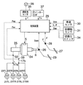
図1は本発明の第一の実施形態を示すシステム構成図であり、運転者の制動操作に依らない自動制動として、運転者の制動操作に先立って予備制動を行なう構成を例示するものである。
【0026】
図中、21FL,21FRは自車両の前輪、21RL,21RRは後輪であって、これら前輪21FL,21FR及び後輪21RL,21RRには夫々ブレーキアクチュエータ22FL,22FR及び22RL,22RRが装着されている。ブレーキアクチュエータ22FL〜22RRの夫々は、後述のマスタシリンダ25から供給される流体圧に応じた制動力を発生するように構成されている。
【0027】
23はブレーキペダルであり、オペレーティングロッド6を介して電子式負圧ブースタ24及びマスタシリンダ25に連結されている。ブレーキペダル23にはその踏込みを検出するブレーキスイッチ26が配設されている。電子式負圧ブースタ24に関しては後に詳述するものとする。
【0028】
マスタシリンダ25の出力側とブレーキアクチュエータ22FL,22FRとの間は配管17aによって、ブレーキアクチュエータ22RL,RRとの間は配管17bによって、それぞれ連通されており、配管17a,17bの夫々には車両で発現する制動力を検出するために流体圧Pw1,Pw2 を検出する二つの圧力センサ32,33が配設されている。これら二つの圧力センサ32,33で検出される流体圧Pw1,Pw2 は本来同じ値を検出するはずであるが、何れか一方に検出誤差が生じたときにでも、システムの制御性を確保するため、後述の演算処理に備えて夫々配管17a,17bに設けるものとする。
【0029】
27はアクセルペダルであり、そのストロークからアクセル開度θを検出するアクセルストロークセンサ28が配設されている。
【0030】
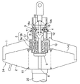
前述の電子式負圧ブースタ24は、図2に示すように、変圧室1と負圧室2とがダイヤフラム14によって画成され、変圧室1はブレーキ非作動時はエンジン負圧によって定まる負圧状態となって、負圧室2と圧力釣り合い状態にあり、ブレーキ作動時には大気が導入され、負圧室2との差圧が生じて、マスタシリンダ25に倍力された荷重が伝達される。負圧室2は、エンジン始動中は常に所定の負圧に維持されている。
【0031】
ダイヤフラム14の中央部には軸筒17が固定され、この軸筒17内に負圧室2と変圧室1とを連通する連通路11が形成され、この連通路11の右端側開口部に真空弁3が配設され、この真空弁3は運転者によってブレーキペダル23がストロークしたとき或いは電磁弁5が励磁されたときに閉じ、負圧室2と変圧室1との連通を遮断する。
【0032】
また、変圧室1と大気との間には大気弁4が配設され、この大気弁4は、後述する摺動筒体5bに形成された弁体12と協働して動作し、運転者によりブレーキペダル23がストロークしたとき或いは電磁弁5が励磁されたときに開き、変圧室1に大気が導入される。
【0033】
電磁弁5は、軸筒17の内周部に配設されたソレノイド5aと、このソレノイド5aと対向して摺動自在に配設された摺動筒体5bとで構成され、摺動筒体5bの右端側に前述した真空弁3及び大気弁4を作動させる係合部18が形成されている。
【0034】
この摺動筒体5bは、負圧室2内に配設されたリターンスプリング15によって右方向に付勢されているとともに、内部には、オペレーティングロッド6が配設され、このオペレーティングロッド6の先端がプッシュロッド8を介してマスタシリンダ25に連結されている。
【0035】
そして、オペレーティングロッド6と軸筒17及び真空弁3,大気弁4との間に夫々リターンスプリング13a及び13bが配設されていると共に、オペレーティングロッド6と摺動筒体5bとの間にリターンスプリング16が配設されている。
【0036】
図1に戻り、30は車速センサであり、変速装置の出力軸回転数から自車速Vmを検出する。31は目標物センサであり、車両の前部に配設されたレーザレーダもしくはミリ波レーダにより車両前方の障害物や先行車両といった目標物までの相対距離Lや相対角θを検出する。34は自動的に予備制動を行うか否かを選択する切替えスイッチ34であり、また35はステアリングホイール36の操舵角δを検出する操舵角センサである。
【0037】
29は制御装置であり、前記ブレーキスイッチ26からのブレーキスイッチ信号SBRK、アクセルストロークセンサ28からのアクセル開度θ、圧力センサ32、33からの制動流体圧Pw1,Pw2 、車速センサ30からの自車速Vm、目標物センサ31からの相対距離L、切替スイッチ34からのスイッチ信号Swに基づき予備制動流体圧目標値PPBを設定し、前記電子式負圧ブースタ24の電磁弁5を制御する予備制動制御処理を行う。また同時に、目標物センサ31からの相対角θ、操舵角センサ35からの操舵角δが入力され、これらから運転者の車線変更意図を判断するとともに、これに応じて予備制動制御処理の抑制を行なう。なお、ここで相対角及び操舵角は、右回りを正とする。
【0038】
次に、前記制御装置29で行われる予備制動制御処理のための演算処理と、当該予備制動制御処理の抑制可否に用いる運転者の車線変更意図を判断するため演算処理とを、それぞれ図3及び図4のフローチャートに従って説明する。なお、これらの演算処理は、所定時間ΔT(例えば10msec. )毎のタイマ割込処理として実行される。なお、このフローチャートでは、特に通信のためのステップを設けていないが、演算によって得られた情報は随時記憶され、記憶されている情報は、必要に応じて、随時読込まれる。
【0039】
(1)予備制動制御処理
まずステップS1にて、同ステップ内で行われる個別の演算処理に従って、前記各センサやスイッチ類の出力、及び後述の車線変更意図判定ルーチン(図4)における判定結果を読込む。
【0040】
次にステップS2に移行して、前記ステップS1で読込んだ各情報の中から自車速Vmを参照する。
【0041】
次にステップS3に移行して、前記ステップS1で読込んだ各情報の中から前方目標物までの相対距離Lを参照する。
【0042】
次にステップS4に移行して、前記相対距離Lの時間微分値から相対距離変化速度dL/dtを算出する。
【0043】
次にステップS5に移行して、前記自車速Vm、前方目標物までの相対距離L、相対距離変化速度dL/dtを用いて、下記1式に従って目標減速度Gx* を算出する。この目標減速度Gx* は自車両が前方目標物に接触しないために必要な減速度を意味する。
【0044】
Gx* ={Vm2−(Vm−dL/dt)2 }/2L… (1)
次にステップS6に移行して、運転者によるブレーキペダル23の踏み込み判断のために、前記ブレーキスイッチ26からのブレーキスイッチ信号SBRK がON状態を示す“1”であるか否かを判定し、当該ブレーキスイッチ信号SBRK がON状態である場合にはステップS14に移行し、そうでない場合にはステップS7に移行する。
【0045】
ステップS7では、前記アクセルストロークセンサ28で検出されたアクセル開度θが、予め設定されたアクセル閉所定値θOFF以上であるか否かを判定し、当該アクセル開度θがアクセル閉所定値θOFF以上である場合にはステップS14に移行し、そうでない場合にはステップS8に移行する。
【0046】
ステップS8では、予備制動制御フラグFPBが“1”のセット状態であるか否かを判定し、当該予備制動制御フラグFPBがセット状態である場合にはステップS12に移行し、そうでない場合にはステップS9に移行する。
【0047】
ステップS9では、ステップS5で算出した目標減速度の絶対値|Gx*|が、予め設定された目標減速度所定値Gx0 *以上である(数値としては目標減速度所定値の負値(−Gx0 *)以下である)か否かを判定し、当該目標減速度の絶対値|Gx0|が目標減速度所定値Gx0 *以上である場合にはステップS10に移行し、そうでない場合にはステップS14に移行する。なお、この目標減速度所定値Gx0 *は、通常運転者が発生しうる減速度近傍の値より若干低い値に設定するが、これは本実施例で発生させる制動力が、運転者の制動操作に先立って発生されるものであり、最終的には運転者の通常制動操作での接触回避を前提としていることによる。
【0048】
ステップS10では、後述の車線変更意図判定ルーチン(図4)にて運転者が車線変更の意図を持っていることを示すフラグLCが“1”であるか否かを判定し、LC=1である場合にはステップS11に移行し、そうでない場合にはステップS14に移行する。
【0049】
ステップS11では、予備制動制御フラグFPBを“1”にセットするとともに、予備制動流体圧目標値PPBを設定する。本実施例の場合、運転者がブレーキペダル23を踏み込んだ際の応答性を向上させることを目的としており、予備制動流体圧目標値PPBは0.1Mpaに設定する。この値は車両に減速Gがほとんど発生しない値であるが、制動効果を重視してより大きな値に設定してもよい。
【0050】
ステップS12では、予備制動制御カウンタCNTをインクリメントする。
【0051】
ステップS13では、予備制動制御カウンタCNTが予備制動カウントアップ所定値CNT0以上であるか否かを判定する。当該予備制動制御カウンタCNTが予備制動カウントアップ所定値CNT0以上である場合にはステップS14に移行し、そうでない場合にはリターンする。ここで、予備制動カウントアップ所定値CNT0は、ステップS9,S10にて予備制動が必要であると判断されてから、運転者がブレーキペダル23を踏み込むであろうと考えられる経過時間を考慮して設定する。本実施例では1秒に設定するが、これは予備制動が必要と判断されてから1秒以内には運転者がブレーキペダル23を踏み込むであろうし、もしそうでない場合は予備制動を必要とした判断が誤判断であったと考えることに基づく。もちろん、この予備制動カウントアップ所定値CNT0は任意に設定可能である。
【0052】
ステップS14では、予備制動制御フラグFPBを“0”にリセットするとともに、予備制動流体圧目標値PPBを0に設定してからリターンする。
【0053】
(2)車線変更意図判断処理
まず、ステップS51にて、同ステップ内で行われる個別の演算処理に従って、前記各センサからの出力を読込む。
【0054】
次にステップS52に移行して、前記ステップS51で読込んだ各情報の中から操舵角δ及び自車速Vmを参照する。
【0055】
次にステップS53に移行して、前記ステップS51で読込んだ各情報の中から前方目標物までの相対距離L及び相対角θを参照する。
【0056】
次にステップS54に移行して、前記相対距離Lの時間微分値から相対距離変化速度dL/dtを算出する。
【0057】
次に、ステップS55に移行して、相対距離変化速度に対する相対距離の割合、すなわち接触時間TCを以下の式によって算出する。
TC=L/(dL/dt)…(2)
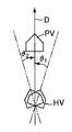
次に、ステップS56に移行して、操舵角δと相対角θとの積から車線変更動作の開始判断を旋回中か直進中かの判断とともに行なう。すなわち、操舵角δと相対角θとの積が所定値γの負の値より小さい場合には直進中に車線変更動作が行われたと判断してステップS57に移行し、操舵角δと相対角θとの積が所定値γより大きい場合には旋回中に車線変更動作が行われたと判断してステップS61に移行する。これは、図5に示すように、道路の進行方向Dが直進であるときに先行車PVを右から追い越す場合、自車両PVは右に操舵するので操舵角δが正になるところ、先行車PVとの相対角θ1は負となることから、操舵角δと相対角θとの積は負となることによる。左から追い越す場合は操舵角δが負、相対角θ2が正となるので、右から追い越す場合と同様に、操舵角δと相対角θとの積は負となる。また、図6(a)に示すように、道路の進行方向Dが右旋回であるときに先行車を右から追い越す場合、自車両PVは右に操舵するので操舵角δは正となり、相対角θ1も正となるので、操舵角δと相対角θとの積は正となることによる。図6(b)に示すように、道路の進行方向Dが左旋回である時に先行車を左から追い越す場合は、操舵角δが負、相対角θ2も負となるので、右旋回の場合と同様に操舵角δと相対角θとの積は正となる。なお、上記いずれにも当てはまらない場合は、車線変更動作が行われていないと判断してステップS66に進む。
【0058】
ステップS57以降ステップS60までは直進時における車線変更意図の判断を示すもので、操舵角δ及び相対角θとが共に大きい場合に車線変更意図ありと判断する。
【0059】
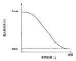
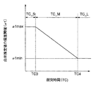
ステップS57では、車線変更意図を判断するための操舵角αに対するしきい値αを、ステップS55にて求めた接触時間TCを用いて決定する。具体的には、図7のmap0に示すように接触時間TCがTC1以下の小さい領域TC_Sにてしきい値αは最大値αmaxとなり、接触時間TCが大きくなるほど(領域TC_M)しきい値αは減少して、接触時間TCがTC2以上の大きい領域TC_Lにてしきい値αは最小値αminとなるように設定する。これは、図8に示すように、接触時間TCが大きいほど操舵角δは小さい傾向となることを考慮しているからである。
【0060】
続いて、ステップS58では、車線変更意図を判断するための相対角θに対するしきい値βを、ステップS52に参照した相対距離Lを用いて決定する。具体的には、図9のmap2に示すように相対距離LがL1以下の小さい領域L_Sにてしきい値βは最大値βmaxとなり、相対距離Lが大きくほど(領域L_M)しきい値βは減少して、相対距離LがL2以上の大きい領域L_Lにてしきい値βは最小値βminとなるように設定する。これは、図10に示すように、相対距離Lが大きいほど相対角θは小さい傾向となることを考慮しているからである。
【0061】
続いて、ステップS59では、操舵角δの絶対値がステップS57にて求めたしきい値αより大きいか否かを判断する。操舵角δがしきい値αより大きいときにはステップS60に移行し、そうでない場合はステップS66に移行する。
【0062】
ステップS60では、相対角θの絶対値がステップS58にて求めたしきい値βより大きいか否かを判断する。相対角θがしきい値βより大きいときにはステップS65に移行し、そうでない場合はステップS66に移行する。
【0063】
一方、ステップS61以降ステップS64までは旋回時における車線変更意図の判断を示すもので、自車両の進路の曲率(以下第一の曲率と称す)と、自車両の位置から目標物の位置まで旋回走行する場合の進路の曲率(以下第二の曲率と称す)との偏差が大きい場合に車線変更意図ありと判断する。
【0064】
ステップS61では、ステップS53にて参照した操舵角δ及び自車速Vmを用いて第一の曲率を以下の式によって算出する。
ρ1=(1+A×Vm2)×l×N/δ…(3)
なお、ここでAはスタビリティーファクター、lはホイールベース、Nはステアリングギヤ比である。
【0065】
次にステップS62では、ステップS52にて参照した相対距離L及び相対角θを用いて第二の曲率を以下の式によって算出する。
ρ2=L/(2×sinθ)…(4)
次にステップS63では、車線変更意図を判断するための上記第一の曲率ρ1と第二の曲率ρ2との偏差Δρに対するしきい値α1を、ステップS55にて求めた接触時間TCを用いて決定する。具体的には、図11に示すように接触時間TCがTC3までの小さい領域TC_Sにてしきい値α1は最大値α1maxとなり、接触時間TCが大きいほど(領域TC_M)しきい値α1は減少して、接触時間TCがTC4以上の大きい領域TC_Lにてしきい値α1は最小値α1minとなるように設定する。これは、図12に示すように、自車HVから目標物としての先行車両への接近度合、すなわち接触時間TCが小さいほど上記第一の曲率ρ1と第二の曲率ρ2との偏差Δρは大きい傾向となることを考慮しているからである。
【0066】
次にステップS64では、ステップS61及びS62にて求めた第一の曲率ρ1と第二の曲率ρ2との偏差Δρの絶対値が、しきい値α1より大きいか否かを判断する。|Δρ|がしきい値α1より大きいときにはステップS65に移行し、そうでない場合はステップS66に移行する。
【0067】
ステップS65では運転者が車線変更の意図を持っていると判断し、車線変更意図判断フラグLCを“1”としてリターンする。
【0068】
一方、ステップS66では運転者が車線変更の意図を持っていないと判断し、車線変更意図判断フラグLCを“0”としてリターンする。
【0069】
以上が、前記制御装置29で行われる予備制動制御処理のための演算処理と、当該予備制動制御処理の抑制可否に用いる運転者の車線変更意図を判断するため演算処理との説明である。
【0070】
次に、本実施例の作用について説明する。
【0071】
自車両前方の障害物や先行車両といった目標物に接近している場合であって、これら目標物に対して接触しないために必要な減速度が所定値を超えた場合には、ブレーキペダル23もしくはアクセルペダル27の踏み込みがない場合に限り、所定時間にわたり予備制動流体圧目標値PPBを所定値に設定して、電子式負圧ブースター24を駆動することにより予備制動制御を実行する。具体的には、真空弁3が閉位置、大気弁4が開位置となるように電磁弁5を駆動し、変圧室1に大気を導入することにより負圧室2との差圧を発生させてマスタシリンダ25とホイルシリンダとの間で液圧を発生させる。予備制動制御中に運転者が制動操作を行なうと、予備制動制御によって予備制動流体圧目標値PPBに相当する圧力が既に発生しているので、運転者の制動操作に対して制動力が迅速に発生する。
【0072】
一方、図4に示した前述の車線変更意図判断処理での判断結果が「運転者の車線変更意図あり」である場合には、予備制動制御を実行しない。これにより、運転者が前方の障害物を回避することや先行車両を追い越す目的で車線変更を意図した際に、運転者に制動の意図がない場合に予備制動が作動して運転者に違和感を与えるという懸念が払拭できる。しかも、図4に示した前述の車線変更意図判断処理では、旋回時においても運転者の車線変更意図を判定可能であるとともに、運転者が仮に脇見をしていた場合には予備制動を確実に実行可能である。
【0073】
以上より、前記目標物センサ31が本発明の相対距離検出手段及び相対角検出手段を構成し、以下同様に、車速センサ30が自車速検出手段を構成し、図3の演算処理全体が制動力制御手段を構成し、図4の演算処理全体が車線変更意図検出手段を構成し、操舵角センサ35が操舵角検出手段を構成し、アクセルペダル27が加速操作手段を構成し、図4の演算処理のステップS61及びS62が第一及び第二の曲率推定手段を構成している。
【0074】
なお、図4の演算処理のステップS63において、しきい値α1を図11に示すように接触時間TCを用いて決定するとして示したが、接触時間TCに代えて、相対距離変化速度dL/dtに対する相対角θの割合である相対角時間TA(下式)を用いてもよい。
TA=θ/ (dL/dt)…(5)
この場合、相対角時間TAにより決定されるΔρに対するしきい値α2は、具体的には、図13に示すように、相対角時間TAがTA1までの小さい領域TA_Sにてしきい値α2は最大値α2maxとなり、相対角時間TAが大きいほど(領域TA_M)しきい値α2は減少して、相対角時間TAがTA2以上の大きい領域TA_Lにてしきい値α2は最小値α2minとなるように設定する。
【0075】
また、相対角時間TAは相対角θの時間的変化を用いて求めるものとしてもよい。
【0076】
また更に、本実施形態では、運転者の車線変更意図を図4に示す車線変更意図判断処理にて行なうこととしたが、これに代えて、ウインカーの操作を検出するウインカースイッチ37を設け、ウインカースイッチ37からのウインカー信号TNが制御装置29に入力されたことで運転者の車線変更意図を判別するものしてもよい。
【0077】
(第二の実施形態)
次に本発明の第二の実施形態について説明する。本実施形態における構成は、図1及び図2に記載した第一の実施形態の構成と共通であるが、第一の実施形態が運転者の制動操作に先立って所定時間にわたり制動力を発生する構成を前提としているのに対し、本実施形態では、目標物に対する接触を防止するための制動力を運転者の制動操作の有無にかかわらず必要に応じて付与する補助制動制御を前提とした構成となっている点が異なる。
【0078】
従って、前記制御装置29で行われる演算処理は、第一実施例における予備制動制御に代えて、目標物との接触を防止するために必要な減速度を求め、その時点で運転者が制動操作を行なっている場合であって運転者の制動操作による減速度が不足する場合や、運転者が制動操作を行なっていない場合に、補助制動を行なうように構成される。
【0079】
そして、本実施形態の場合も、運転者の車線変更意図が検出された場合には、この補助制動制御を一部抑制するように構成されている。なお、運転者の車線変更意図を検出するための演算処理は第一の実施形態と同様である。
【0080】
前記制御装置29で行われる補助制動制御のための演算処理を、以下の通り図14のフローチャートに基づいて説明する。
【0081】
まずステップS101にて、同ステップ内で行われる個別の演算処理に従って、前記各センサやスイッチ類の出力、及び後述の車線変更意図判定ルーチン(図4)における判定結果を読込む。
【0082】
車速センサ30からの自車速Vmが読込まれる。
【0083】
次に、ステップS102にて、前記ステップS101で読込んだ各情報の中から自車速Vmを参照する。
【0084】
次にステップS103にて、前記ステップS101で読込んだ各情報の中から前方目標物までの相対距離Lを参照する。
【0085】
次にステップS104にて、相対距離Lの時間微分値から相対距離変化速度dL/dtを算出する。
【0086】
次にステップS105にて、自車速Vmと相対距離変化速度dL/dtとから前方対象物の速度(前方対象物が先行車両の場合はその車速)Vfを算出し、前方対象物の速度Vfがゼロ、すなわち前方対象物が停止物であるか否かを判別する。前方対象物の速度Vfがゼロでなく、停止物ではない場合はステップS109に進み、1周期前の先行車両の車速Vfoldとの変化量を計算し、それが所定値αよりも小さい場合はステップS110へ進み、そうでない場合はステップS111へ進む。ここでαは1.0Gとし、それより大きい変化量は同一車両の車速変化として物理的にありえないため、対象物が別のものに移ったと推定できる。そして、この場合は、ステップS111で前方対象物が連続的に検出できているかどうかの状態を示すフラグconflgをクリアし、次回の制御サイクルで使用する先行車両の車速(1周期前の先行車両の車速)Vfoldをありえない値1000に設定する。
【0087】
一方、Sステップ109で先行車両の車速Vfが物理的に変化できる値であると判断した場合はステップS110へ進み、前方対象物としての先行車両が連続的に検出できているかどうかの状態を示すフラグconflgを1にセットし、次の制御サイクルで使用するために、先行車両の車速(1周期前の先行車両の車速)Vfold=Vfとしてメモリに格納する。
【0088】
ステップS105の判定で、前方対象物が停止物と判断された場合はステップS106へ進み、前述のフラグconflgを調べる。conflg=1、すなわち前方対象物が連続的に停止している場合はステップS110以降へ進むが、conflg=0、すなわちもともと停止している物体が対象となっていない場合は、センサの検出精度の問題から、ステップS107で制御をオフしてステップS108で制御を終了する。
【0089】
ステップS112では、前方対象物に接触せずに停止するために必要な目標減速度Gx*が、第一の実施形態の図3と同様に以下の式によって計算される。
Gx*={Vm2 −(Vm−dL/dt)2 }/2L…(1)
ステップS113では、ステップ112で得られた目標減速度Gx*に基づいて、その減速度を実現するための目標液圧Ptを求める。
【0090】
ステップS114では圧力センサ32、33の制動流体圧Pw1,Pw2 から実液圧Prを求める。
【0091】
ステップS115では目標液圧Ptが実際の液圧Prよりも大きいか否かを判断する。目標液圧Ptが実際の液圧Prよりも大きい場合、すなわち運転者のブレーキ操作されていないか若しくは不十分な場合はステップS116に移行するが、目標液圧Ptが実際の液圧Prよりも小さい場合、すなわち運転者のブレーキ操作が十分な場合はステップS119に進み、本補助制動制御を非作動とする。
【0092】
ステップS116では、車線変更意図判定処理(前述の第一の実施形態の図4)にて運転者が車線変更の意図を持っていることを示すフラグLCが“1”であるか否かを判定し、LC=1である場合にはステップS118に移行し、そうでない場合にはステップS117に移行する。
【0093】
ステップS117では、実際の液圧Prが目標液圧Ptとなるように、電子式負圧ブースタ24を作動させることで増圧制御を行なう。
【0094】
一方、ステップS118では、増圧制御をステップS117にて実行されるものに比して制限して実行する。このため、本ステップにおいては補正目標液圧Pt*を以下の式により、車線変更意図判定処理(前述の第一の実施形態の図4)にて算出した接触時間TC及び相対角θに応じて変更されるゲインk1、k2を乗じることで求め、実際の液圧Prがこの補正目標液圧Pt*を下回っている場合に限って、実際の液圧Prが補正目標液圧Pt*となるように、電子式負圧ブースタ24を作動させる。
Pt*=k1×k2×Pt…(6)
ここで、ゲインk1は図15に示すように、接触時間TCが小さい領域では最大値1をとり、接触時間が大きくなるほど低下される特性である。また、ゲインk2は図16に示すように、目標物との相対角θが小さい領域では最大値1をとり、相対角θが大きくなるほど低下される特性である。これらの特性は、接触時間TCが大きくなるほど、また相対角が大きくなるほど、運転者の車線変更の意図は強いと考えられるためである。
【0095】
その他の構成は第一の実施形態と同様である。
【0096】
次に、本実施形態の作用について説明する。
【0097】
自車両前方の障害物や先行車両といった目標物に接近している場合であって、これら目標物に対して接触しないために必要な減速度が計算され、この減速度を実現するために必要な目標液圧Ptが算出される。そして、実際の液圧Prが目標液圧Ptを下回っている場合には、実際の液圧Prを目標液圧Ptに持ち来すよう、電子式負圧ブースター24を駆動することにより補助制動制御が実行される。具体的には、真空弁3が閉位置、大気弁4が開位置となるように電磁弁5を駆動し、変圧室1に大気を導入することにより負圧室2との差圧を発生させてマスタシリンダ25とホイルシリンダとの間で液圧を発生させる。
【0098】
一方、図4に示した前述の車線変更意図判断処理での判断結果が「運転者の車線変更意図あり」である場合には、補助制動制御を制限、すなわち車線変更意図が検出されていない場合よりも補助制動制御による目標液圧を低下させる。これにより、運転者が前方の障害物を回避することや先行車両を追い越す目的で車線変更を意図した際に、運転者に制動の意図がない場合や、運転者が現在の制動操作により発生させている以上の制動力が必要ではないと認識している場合において、補助制動が作動して運転者に違和感を与えるという懸念が払拭できる。しかも、第一の実施形態と同様に、図4に示した前述の車線変更意図判断処理では、旋回時においても運転者の車線変更意図を判定可能であるとともに、運転者が仮に脇見をしていた場合には予備制動を確実に実行可能である。更に加え、車線変更意図が検出されている場合の補助制動制御による目標液圧は、接触時間TCが大きくなるほど低下され、また目標物との相対角θが大きくなるほど低下されるため、運転者の車線変更の意図に合致させたものとできる。
【0099】
【発明の効果】
請求項1記載の構成によれば、運転者が前方の障害物を回避することや先行車両を追い越す目的で車線変更を意図した際に、運転者に制動の意図がない場合に自動制動が作動して運転者に違和感を与えるという懸念を払拭でき、また、操舵角及び目標物との相対角がそれぞれ所定値以上である場合に運転者の車線変更の意図ありと判断するので、前記車線変更の意図を的確に判断でき、しかも、相対速度に対する相対距離の割合を考慮して運転者の車線変更意図を判断するので、前記車線変更の意図をより的確に判断できる。
【0102】
請求項2記載の構成によれば、相対距離を考慮して運転者の車線変更意図を判断するので、前記車線変更の意図をより的確に判断できる。
【0103】
請求項3記載の構成によれば、運転者が前方の障害物を回避することや先行車両を追い越す目的で車線変更を意図した際に、運転者に制動の意図がない場合に自動制動が作動して運転者に違和感を与えるという懸念を払拭でき、また、自車両の進路の曲率と、自車両の位置から目標物の位置まで旋回走行した場合の進路の曲率との比較で運転者の車線変更意図を判断するので、旋回時においても前記車線変更の意図を的確に判断でき、しかも、相対速度に対する相対距離の割合を考慮して運転者の車線変更意図を判断するので、旋回時において前記車線変更の意図をより的確に判断できる。
【0105】
請求項4記載の構成によれば、相対速度に対する相対距離の割合を考慮し、また請求項5記載の構成によれば、相対角度を考慮して自動制動を低減するので、運転者の車線変更の意図に沿った自動制動となすことができる。
【図面の簡単な説明】
【図1】本発明の第一の実施の形態におけるシステムを示す構成図である。
【図2】本発明の第一の実施の形態における負圧ブースターの構成を示す図である。
【図3】本発明の第一の実施の形態における制御装置にて実行される、予備制動制御の演算処理を示すフローチャートである。
【図4】本発明の第一の実施の形態における制御装置にて実行される、車線変更意図判断の演算処理を示すフローチャートである。
【図5】直進時における車線変更動作の開始判断について説明する図である。
【図6】旋回時における車線変更動作の開始判断について説明する図である。
【図7】操舵角に対するしきい値と接触時間との特性を示す図である。
【図8】操舵角と接触時間とに関する特性図である。
【図9】相対角に対するしきい値と相対距離との特性を示す図である。
【図10】相対角と相対距離とに関する特性図である。
【図11】第一の曲率と第二の曲率との偏差に対するしきい値と、接触時間との特性を示す図である。
【図12】第一の曲率と第二の曲率との偏差と、接触時間との特性を示す図である。
【図13】第一の曲率と第二の曲率との偏差に対する別のしきい値の特性を示す図である。
【図14】本発明の第二の実施の形態における制御装置にて実行される、補助制動制御の演算処理を示すフローチャートである。
【図15】補正目標液圧算出に関わるゲインK1の特性図である。
【図16】補正目標液圧算出に関わるゲインK2の特性図である。
【符号の説明】
1 変圧室
2 負圧室
3 真空弁
4 大気弁
5 電磁弁
6 オペレーティングロッド
8 プッシュロッド
23 ブレーキペダル
24 電子式負圧ブースタ
25 マスタシリンダ
26 ブレーキスイッチ
27 アクセルペダル
29 制御装置
30 車速センサ
31 目標物センサ[0001]
BACKGROUND OF THE INVENTION
The present invention relates to a braking control device that performs automatic braking independent of a driver's braking operation when the host vehicle approaches a target such as an obstacle or a preceding vehicle ahead of the host vehicle.
[0002]
[Prior art]
2. Description of the Related Art Conventionally, a technique for performing automatic braking by determining the possibility of contact from the distance and relative speed between a host vehicle and a target such as a front obstacle or a preceding vehicle is known.
[0003]
Based on the above technology, in order to prevent the automatic braking from being inadvertently activated when the target is a preceding vehicle and overtaking, the relative speed is equal to or lower than a predetermined value and the acceleration of the own vehicle is a predetermined value. In the case described above, a configuration for determining that the contact possibility is low is disclosed in Japanese Patent Laid-Open No. Hei 5-242396 (hereinafter referred to as the first prior art).
[0004]
Similarly, in order to prevent the steered wheels from slipping, a configuration in which the braking force is reduced or zeroed when steering is performed during automatic braking is disclosed in Japanese Patent Laid-Open No. 5-58257 (hereinafter referred to as the second method). (Referred to as prior art).
[0005]
[Problems to be solved by the invention]
In the first prior art described above, since the contact possibility is determined using only the relative speed and the acceleration of the own vehicle, automatic braking does not operate in a situation where the driver approaches the preceding vehicle due to a lookout by the driver. There is a concern that it is possible.
[0006]
On the other hand, in the second prior art, since the braking force is reduced or made zero only by steering, there is a concern that the automatic braking may not operate even during turning.
[0007]
The present invention solves the above problems by accurately determining the driver's intention to avoid obstacles and overtake the preceding vehicle, in other words, the intention to change lanes. It is an object of the present invention to provide a braking control device that can prevent as much as possible.
[0008]
[Means for solving the problems]
In order to solve the above-described problems, a braking control device according to the present invention, as described in
[0011]
Claims2The braking control apparatus according to the second aspect is configured such that the second predetermined value decreases as the relative distance increases.
[0012]
In order to solve the above problem, a braking control device according to the present invention is as described in claim 3.,Relative distance detecting means for detecting a relative distance to a target in front of the vehicle, own vehicle speed detecting means for detecting the speed of the own vehicle, and the relative distance detected by the relative distance detecting means and the own vehicle speed detecting means. And braking force control means for controlling a braking force for performing automatic braking not depending on a driver's braking operation when the host vehicle is approaching a target ahead of the vehicle based on the host vehicle speed. A lane change intention detection means for detecting a driver's intention to change lanes,Steering angle detecting means for detecting a steering angle, relative angle detecting means for detecting a relative angle with respect to the target, and a first curvature for estimating the curvature of the course of the host vehicle using the host vehicle speed and the steering angle. Estimating means, and second curvature estimating means for estimating the curvature of the course when turning from the position of the own vehicle to the position of the target object from the relative distance and the relative angle,furtherAnd the lane change intention detection means has a deviation between the curvature estimated by the first curvature estimation means and the curvature estimated by the second curvature estimation means is a third predetermined value or more, Judgment that the driver's lane change is intendedIn addition, as the ratio of the relative distance to the relative speed obtained from the relative distance increases, the third predetermined value is made smaller. The braking force control means detects the driver's intention to change lanes. Limit the automatic braking whenIt is comprised so that it may do.
[0014]
Claims4In the braking control device according to the present invention, the braking force control means is configured to limit the automatic braking executed when the driver's intention to change the lane is detected as the ratio of the relative distance to the relative speed obtained from the relative distance increases. Degree ofBigIt is comprised so that.
[0015]
Claims5In the braking control device according to the present invention, the braking force control means increases the degree of restriction of the automatic braking that is executed when the driver's intention to change the lane is detected as the relative angle increases.BigIt is comprised so that.
[0016]
[Action]
According to the first aspect of the present invention, the braking force control means limits the automatic braking to be reduced or stopped when the driver's intention to change lanes is detected.
[0017]
Also,If the steering angle is greater than or equal to the first predetermined value and the relative angle to the target is greater than or equal to the second predetermined value, the lane is for the purpose of the driver avoiding an obstacle or overtaking the preceding vehicle Judge that the change is intended.
[0018]
AndIn view of the fact that the greater the ratio of the relative distance to the relative speed, the smaller the steering angle required for obstacle avoidance and overtaking of the preceding vehicle, the smaller the ratio is set compared to the case where the ratio of the relative distance to the relative speed is small. A lane change intention is determined using the first predetermined value.
[0019]
Claim2According to the described configuration, the larger the relative distance, the smaller the relative angle with the preceding vehicle when avoiding obstacles and overtaking the preceding vehicle, so that it is set smaller than when the relative distance is small. A lane change intention is determined using the second predetermined value.
[0020]
Claim3According to the configuration describedEven so, the braking force control means limits the automatic braking to be reduced or stopped when the driver's intention to change lanes is detected.
Also,When turning, the first curvature, which is the curvature of the own vehicle's path, and the curvature of the path when the vehicle is turning from the position of the own vehicle to the target position, for example, the own vehicle has taken the same path as the preceding vehicle. Compare the second curvature, which is the curvature of the course of the case, and if these deviations are greater than or equal to the third predetermined value, i.e., the situation where the host vehicle does not take the same course as the preceding vehicle, determine the intention to change lanes To do.
[0021]
AndThe greater the ratio of the relative distance to the relative speed, the greater the deviation between the predicted course of the vehicle and the course when turning to the target position when avoiding obstacles or overtaking the preceding vehicle, that is, the first curvature. Since the difference between the second curvature and the second curvature is small, the intention to change the lane is determined using the third predetermined value set smaller than when the ratio of the relative distance to the relative speed is small.
[0022]
Claim4According to the described configuration, the automatic braking is reduced as the ratio of the relative distance to the relative speed increases.
[0023]
Claim5According to the described configuration, the automatic braking is reduced as the relative angle increases.
[0024]
DETAILED DESCRIPTION OF THE INVENTION
Hereinafter, embodiments of the present invention will be described with reference to the drawings.
[0025]
(First embodiment)
FIG. 1 is a system configuration diagram showing a first embodiment of the present invention, and illustrates a configuration in which preliminary braking is performed prior to a driver's braking operation as automatic braking not depending on the driver's braking operation. .
[0026]
In the figure, 21FL and 21FR are front wheels of the host vehicle, 21RL and 21RR are rear wheels, and brake actuators 22FL, 22FR and 22RL and 22RR are mounted on the front wheels 21FL and 21FR and the rear wheels 21RL and 21RR, respectively. . Each of the brake actuators 22FL to 22RR is configured to generate a braking force according to a fluid pressure supplied from a
[0027]
A
[0028]
The output side of the
[0029]
An
[0030]
As shown in FIG. 2, the electronic
[0031]
A
[0032]
Also, an
[0033]
The
[0034]
The sliding
[0035]
Return springs 13a and 13b are disposed between the operating
[0036]
Returning to FIG. 1,
[0037]
A control device 29 is a brake switch signal S from the brake switch 26.BRK, Accelerator opening θ from the
[0038]
Next, the calculation process for the preliminary braking control process performed by the control device 29 and the calculation process for determining the driver's intention to change the lane used for the suppression of the preliminary brake control process are respectively shown in FIG. This will be described with reference to the flowchart of FIG. Note that these arithmetic processes are executed as a timer interrupt process every predetermined time ΔT (for example, 10 msec.). In this flowchart, no particular communication step is provided, but information obtained by calculation is stored as needed, and stored information is read as needed.
[0039]
(1) Preliminary braking control processing
First, in step S1, the output of each sensor and switches and the determination result in a lane change intention determination routine (FIG. 4) to be described later are read according to individual calculation processing performed in the step.
[0040]
Next, the process proceeds to step S2, and the own vehicle speed Vm is referred to from among the information read in step S1.
[0041]
Next, the process proceeds to step S3, and the relative distance L from the information read in step S1 to the front target is referred to.
[0042]
Next, the process proceeds to step S4, where the relative distance change speed dL / dt is calculated from the time differential value of the relative distance L.
[0043]
Next, the process proceeds to step S5, and the target deceleration Gx according to the
[0044]
Gx* = {Vm2− (Vm−dL / dt)2 } / 2L ... (1)
Next, the process proceeds to step S6, where the brake switch signal S from the
[0045]
In step S7, the accelerator opening degree θ detected by the
[0046]
In step S8, the preliminary braking control flag FPBIs set to "1", and the preliminary braking control flag F is determined.PBIf is in the set state, the process proceeds to step S12. If not, the process proceeds to step S9.
[0047]
In step S9, the absolute value of the target deceleration calculated in step S5 | Gx*Is a predetermined target deceleration predetermined value Gx0 *(The numerical value is a negative value of the target deceleration predetermined value (−Gx0 *) Or less), and the absolute value of the target deceleration | Gx0| Is the target deceleration predetermined value Gx0 *If so, the process proceeds to step S10, and if not, the process proceeds to step S14. The target deceleration predetermined value Gx0 *Is set to a value slightly lower than the value near the deceleration that can be generated by the normal driver, but this is the braking force generated in this embodiment is generated prior to the driver's braking operation, Finally, it is based on the premise that the driver avoids contact during normal braking operation.
[0048]
In step S10, it is determined in a lane change intention determination routine (FIG. 4), which will be described later, whether or not a flag LC indicating that the driver has an intention to change lanes is “1”. If there is, the process proceeds to step S11, and if not, the process proceeds to step S14.
[0049]
In step S11, the preliminary braking control flag FPBIs set to “1” and the preliminary braking fluid pressure target value P is set.PBSet. In this embodiment, the purpose is to improve the response when the driver depresses the
[0050]
In step S12, the preliminary braking control counter CNT is incremented.
[0051]
In step S13, the preliminary braking control counter CNT counts the preliminary braking count-up predetermined value CNT.0It is determined whether it is above. The preliminary braking control counter CNT is set to the preliminary braking count-up predetermined value CNT.0If so, the process proceeds to step S14, and if not, the process returns. Here, preliminary braking count up predetermined value CNT0Is set in consideration of the elapsed time during which it is considered that the driver will step on the
[0052]
In step S14, the preliminary braking control flag FPBIs reset to “0” and the preliminary braking fluid pressure target value PPBSet to 0 and return.
[0053]
(2) Lane change intention determination process
First, in step S51, the output from each sensor is read in accordance with individual calculation processing performed in the step.
[0054]
Next, the process proceeds to step S52, and the steering angle δ and the own vehicle speed Vm are referred to from among the information read in step S51.
[0055]
Next, the process proceeds to step S53, and the relative distance L and the relative angle θ to the front target are referred to from among the information read in step S51.
[0056]
Next, the process proceeds to step S54, where the relative distance change speed dL / dt is calculated from the time differential value of the relative distance L.
[0057]
Next, the process proceeds to step S55, where the ratio of the relative distance to the relative distance change speed, that is, the contact time TC is calculated by the following equation.
TC = L / (dL / dt) (2)
Next, the process proceeds to step S56, where the start determination of the lane change operation is made from the product of the steering angle δ and the relative angle θ together with the determination whether the vehicle is turning or going straight. That is, if the product of the steering angle δ and the relative angle θ is smaller than the negative value of the predetermined value γ, it is determined that the lane change operation has been performed while traveling straight, and the process proceeds to step S57, where the steering angle δ and the relative angle are If the product of θ is greater than the predetermined value γ, it is determined that the lane change operation has been performed during the turn, and the process proceeds to step S61. As shown in FIG. 5, when the vehicle is overtaking the preceding vehicle PV from the right when the traveling direction D of the road is straight, the vehicle PV is steered to the right so that the steering angle δ becomes positive. Relative angle with PV1Is negative, the product of the steering angle δ and the relative angle θ is negative. When overtaking from the left, steering angle δ is negative, relative angle θ2Is positive, the product of the steering angle δ and the relative angle θ is negative, as in the case of overtaking from the right. As shown in FIG. 6 (a), when the preceding vehicle is overtaken from the right when the traveling direction D of the road is a right turn, the own vehicle PV is steered to the right, so that the steering angle δ becomes positive and the relative Angle θ1Is also positive, because the product of the steering angle δ and the relative angle θ is positive. As shown in FIG. 6B, when the vehicle is overtaking from the left when the road traveling direction D is a left turn, the steering angle δ is negative and the relative angle θ2Therefore, the product of the steering angle δ and the relative angle θ is positive as in the case of right turn. If none of the above applies, it is determined that the lane change operation is not performed, and the process proceeds to step S66.
[0058]
Step S57 to step S60 indicate determination of lane change intention during straight traveling. When both the steering angle δ and the relative angle θ are large, it is determined that the lane change intention is present.
[0059]
In step S57, a threshold value α with respect to the steering angle α for determining the intention to change the lane is determined using the contact time TC obtained in step S55. Specifically, as shown by map0 in FIG. 7, the threshold value α becomes the maximum value αmax in a small region TC_S where the contact time TC is TC1 or less, and the threshold value α becomes larger as the contact time TC increases (region TC_M). The threshold value α is set to be the minimum value αmin in the large region TC_L where the contact time TC is greater than or equal to TC2 by decreasing. This is because, as shown in FIG. 8, it is considered that the steering angle δ tends to decrease as the contact time TC increases.
[0060]
Subsequently, in step S58, the threshold value β with respect to the relative angle θ for determining the intention to change the lane is determined using the relative distance L referred to in step S52. Specifically, as shown by map2 in FIG. 9, the threshold value β becomes the maximum value βmax in the small region L_S where the relative distance L is equal to or less than L1, and the threshold value β increases as the relative distance L increases (region L_M). The threshold value β is set to be the minimum value βmin in the large region L_L where the relative distance L is greater than L2 by decreasing. This is because it is considered that the relative angle θ tends to decrease as the relative distance L increases as shown in FIG.
[0061]
Subsequently, in step S59, it is determined whether or not the absolute value of the steering angle δ is larger than the threshold value α obtained in step S57. When the steering angle δ is larger than the threshold value α, the process proceeds to step S60. Otherwise, the process proceeds to step S66.
[0062]
In step S60, it is determined whether or not the absolute value of the relative angle θ is larger than the threshold value β obtained in step S58. When the relative angle θ is larger than the threshold value β, the process proceeds to step S65, and otherwise, the process proceeds to step S66.
[0063]
On the other hand, from step S61 to step S64 indicate judgment of lane change intention at the time of turning, and turn from the position of the own vehicle to the target position from the position of the own vehicle (hereinafter referred to as the first curvature). When there is a large deviation from the curvature of the course when traveling (hereinafter referred to as the second curvature), it is determined that there is a lane change intention.
[0064]
In step S61, the first curvature is calculated by the following equation using the steering angle δ and the vehicle speed Vm referred to in step S53.
ρ1 = (1 + A × Vm2) × l × N / δ (3)
Here, A is a stability factor, l is a wheel base, and N is a steering gear ratio.
[0065]
Next, in step S62, the second curvature is calculated by the following equation using the relative distance L and the relative angle θ referred to in step S52.
ρ2 = L / (2 × sin θ) (4)
Next, in step S63, a threshold value α1 for the deviation Δρ between the first curvature ρ1 and the second curvature ρ2 for determining the lane change intention is determined using the contact time TC obtained in step S55. To do. Specifically, as shown in FIG. 11, the threshold value α1 becomes the maximum value α1max in the region TC_S where the contact time TC is small up to TC3, and the threshold value α1 decreases as the contact time TC increases (region TC_M). Thus, the threshold value α1 is set to be the minimum value α1min in the large region TC_L where the contact time TC is greater than or equal to TC4. As shown in FIG. 12, the deviation Δρ between the first curvature ρ1 and the second curvature ρ2 increases as the degree of approach from the own vehicle HV to the preceding vehicle as the target, that is, the contact time TC decreases. It is because it considers becoming a tendency.
[0066]
Next, in step S64, it is determined whether or not the absolute value of the deviation Δρ between the first curvature ρ1 and the second curvature ρ2 obtained in steps S61 and S62 is greater than a threshold value α1. When | Δρ | is larger than the threshold value α1, the process proceeds to step S65. Otherwise, the process proceeds to step S66.
[0067]
In step S65, it is determined that the driver has an intention to change lanes, and the lane change intention determination flag LC is set to “1” and the process returns.
[0068]
On the other hand, in step S66, it is determined that the driver has no intention to change lanes, and the lane change intention determination flag LC is set to “0” and the process returns.
[0069]
The above is the description of the calculation process for the preliminary braking control process performed by the control device 29 and the calculation process for determining the driver's intention to change the lane used for suppressing the preliminary brake control process.
[0070]
Next, the operation of this embodiment will be described.
[0071]
When the vehicle is approaching a target such as an obstacle in front of the host vehicle or a preceding vehicle, and the deceleration required to avoid contact with the target exceeds a predetermined value, the
[0072]
On the other hand, if the determination result in the above-described lane change intention determination process shown in FIG. 4 is “the driver intends to change lane”, the preliminary braking control is not executed. As a result, when the driver intends to change lanes in order to avoid obstacles ahead or overtake the preceding vehicle, pre-braking is activated and the driver feels uncomfortable if the driver does not intend to brake. The concern of giving can be dispelled. In addition, in the above-described lane change intention determination process shown in FIG. 4, it is possible to determine the driver's intention to change lanes even during a turn, and to ensure preliminary braking if the driver is looking aside. It is feasible.
[0073]
From the above, the
[0074]
In FIG. 4, in step S63 of the calculation process, the threshold value α1 is shown to be determined using the contact time TC as shown in FIG. 11, but the relative distance change speed dL / dt is used instead of the contact time TC. You may use relative angle time TA (following formula) which is a ratio of relative angle theta to.
TA = θ / (dL / dt) (5)
In this case, the threshold value α2 with respect to Δρ determined by the relative angular time TA is specifically, as shown in FIG. 13, the threshold value α2 is maximum in a region TA_S where the relative angular time TA is small up to TA1. The threshold value α2 decreases as the relative angle time TA increases (area TA_M) as the relative angle time TA increases, and the threshold value α2 is set to the minimum value α2min in the area TA_L where the relative angle time TA is greater than TA2. To do.
[0075]
Further, the relative angle time TA may be obtained using a temporal change in the relative angle θ.
[0076]
Furthermore, in this embodiment, the driver's intention to change the lane is determined by the lane change intention determination process shown in FIG. 4, but instead, a
[0077]
(Second embodiment)
Next, a second embodiment of the present invention will be described. The configuration of this embodiment is the same as that of the first embodiment described in FIGS. 1 and 2, but the first embodiment generates a braking force for a predetermined time prior to the driver's braking operation. In contrast to the premise of the configuration, in the present embodiment, the premise is an auxiliary brake control in which a braking force for preventing contact with the target is applied as necessary regardless of the presence or absence of the driver's braking operation. Is different.
[0078]
Therefore, the arithmetic processing performed by the control device 29 is to obtain the deceleration required to prevent contact with the target instead of the preliminary braking control in the first embodiment, and the driver performs the braking operation at that time. And when the deceleration due to the braking operation of the driver is insufficient, or when the driver is not performing the braking operation, auxiliary braking is performed.
[0079]
And also in this embodiment, when the driver's intention to change lanes is detected, this auxiliary braking control is partially suppressed. Note that the arithmetic processing for detecting the driver's intention to change lanes is the same as in the first embodiment.
[0080]
The arithmetic processing for auxiliary braking control performed by the control device 29 will be described based on the flowchart of FIG. 14 as follows.
[0081]
First, in step S101, the outputs of the sensors and switches and the determination result in a lane change intention determination routine (FIG. 4) described later are read in accordance with individual calculation processing performed in the step.
[0082]
The own vehicle speed Vm from the
[0083]
Next, in step S102, the vehicle speed Vm is referred to from among the information read in step S101.
[0084]
Next, in step S103, the relative distance L from the information read in step S101 to the front target is referred to.
[0085]
Next, in step S104, the relative distance change speed dL / dt is calculated from the time differential value of the relative distance L.
[0086]
Next, in step S105, the speed of the front object (or the vehicle speed when the front object is a preceding vehicle) Vf is calculated from the own vehicle speed Vm and the relative distance change speed dL / dt. It is determined whether it is zero, that is, whether the front object is a stop object. If the speed Vf of the front object is not zero and the object is not a stop, the process proceeds to step S109, and the amount of change from the vehicle speed Vfold of the preceding vehicle one cycle before is calculated, and if it is smaller than the predetermined value α, step It progresses to S110, and when that is not right, it progresses to step S111. Here, α is set to 1.0 G, and a larger change amount cannot physically be a change in the vehicle speed of the same vehicle. Therefore, it can be estimated that the object has moved to another object. In this case, in step S111, the flag conflg indicating whether or not the front object can be continuously detected is cleared, and the vehicle speed of the preceding vehicle used in the next control cycle (the preceding vehicle of the preceding vehicle one cycle) is cleared. Vehicle speed) Vfold is set to an impossible value of 1000.
[0087]
On the other hand, if it is determined in step S109 that the vehicle speed Vf of the preceding vehicle is a value that can be physically changed, the process proceeds to step S110 and indicates whether or not the preceding vehicle as the front object is continuously detected. The flag conflg is set to 1 and stored in the memory as the vehicle speed of the preceding vehicle (vehicle speed of the preceding vehicle one cycle before) Vfold = Vf for use in the next control cycle.
[0088]
If it is determined in step S105 that the front object is a stopped object, the process proceeds to step S106, and the above-described flag conflg is examined. If conflg = 1, that is, if the front object is continuously stopped, the process proceeds to step S110 and after. However, if conflg = 0, that is, if the object that was originally stopped is not the target, the detection accuracy of the sensor is increased. Due to the problem, the control is turned off in step S107 and the control is terminated in step S108.
[0089]
In step S112, the target deceleration Gx necessary for stopping without contacting the front object.*Is calculated by the following equation in the same manner as in FIG. 3 of the first embodiment.
Gx*= {Vm2 − (Vm−dL / dt)2 } / 2L ... (1)
In step S113, the target deceleration Gx obtained in step 112 is obtained.*Based on the above, the target hydraulic pressure Pt for realizing the deceleration is obtained.
[0090]
In step S114, the actual hydraulic pressure Pr is obtained from the brake fluid pressures Pw1, Pw2 of the pressure sensors 32, 33.
[0091]
In step S115, it is determined whether or not the target hydraulic pressure Pt is larger than the actual hydraulic pressure Pr. When the target hydraulic pressure Pt is larger than the actual hydraulic pressure Pr, that is, when the driver's brake operation is not performed or insufficient, the process proceeds to step S116, but the target hydraulic pressure Pt is higher than the actual hydraulic pressure Pr. If it is smaller, that is, if the driver's braking operation is sufficient, the process proceeds to step S119, and this auxiliary braking control is deactivated.
[0092]
In step S116, it is determined whether or not the flag LC indicating that the driver has the intention to change lanes is “1” in the lane change intention determination processing (FIG. 4 of the first embodiment described above). If LC = 1, the process proceeds to step S118. Otherwise, the process proceeds to step S117.
[0093]
In step S117, pressure increase control is performed by operating the electronic
[0094]
On the other hand, in step S118, the pressure increase control is limited and executed as compared with that executed in step S117. Therefore, in this step, the corrected target hydraulic pressure Pt*The gain k is changed according to the contact time TC and the relative angle θ calculated in the lane change intention determination process (FIG. 4 of the first embodiment described above) by the following equation.1, K2The actual hydraulic pressure Pr is obtained by multiplying the corrected target hydraulic pressure Pt by*Only when the actual hydraulic pressure Pr is less than the corrected target hydraulic pressure Pt.*The electronic
Pt*= K1× k2× Pt (6)
Where gain k1As shown in FIG. 15, the maximum value is 1 in a region where the contact time TC is small, and the characteristic decreases as the contact time increases. Also, gain k2As shown in FIG. 16, the maximum value is 1 in a region where the relative angle θ to the target is small, and the characteristic decreases as the relative angle θ increases. These characteristics are because the driver's intention to change lanes is considered to be stronger as the contact time TC increases and the relative angle increases.
[0095]
Other configurations are the same as those of the first embodiment.
[0096]
Next, the operation of this embodiment will be described.
[0097]
When the vehicle is approaching a target such as an obstacle or a preceding vehicle in front of the host vehicle, the deceleration required to avoid contact with the target is calculated, and it is necessary to realize this deceleration. A target hydraulic pressure Pt is calculated. When the actual hydraulic pressure Pr is lower than the target hydraulic pressure Pt, auxiliary braking control is performed by driving the electronic
[0098]
On the other hand, if the determination result in the above-described lane change intention determination process shown in FIG. 4 is “the driver has a lane change intention”, the auxiliary braking control is limited, that is, the lane change intention is not detected. Rather than lowering the target hydraulic pressure by the auxiliary braking control. As a result, when the driver intends to change lanes in order to avoid obstacles ahead or overtake the preceding vehicle, the driver does not intend to brake or is generated by the current braking operation. In the case where it is recognized that more braking force than necessary is not necessary, the concern that the auxiliary braking is activated and the driver feels uncomfortable can be eliminated. In addition, as in the first embodiment, the above-described lane change intention determination process shown in FIG. 4 can determine the driver's lane change intention even when turning, and the driver temporarily looks aside. In this case, the preliminary braking can be surely executed. In addition, the target hydraulic pressure by the auxiliary braking control when the intention to change the lane is detected decreases as the contact time TC increases, and decreases as the relative angle θ with the target increases. It can be matched to the intention of changing lanes.
[0099]
【The invention's effect】
According to the configuration of the first aspect, when the driver intends to change lanes for the purpose of avoiding obstacles ahead or overtaking the preceding vehicle, automatic braking is activated when the driver does not intend to brake. To relieve the concern of discomfort to the driverIn addition, when the steering angle and the relative angle to the target are each equal to or greater than a predetermined value, it is determined that the driver intends to change the lane, so the intention to change the lane can be accurately determined, and the relative speed can be determined. Since the driver's intention to change lane is determined in consideration of the relative distance ratio, the intention to change the lane can be determined more accurately.The
[0102]
Claim2According to the described configuration, the driver's intention to change the lane is determined in consideration of the relative distance, and therefore the intention to change the lane can be determined more accurately.
[0103]
Claim3According to the configuration described,Concerns that when the driver intends to change lanes in order to avoid obstacles ahead or overtake the preceding vehicle, automatic braking is activated and the driver feels uncomfortable if the driver does not intend to brake Can also wipe offThe driver's intention to change the lane is determined by comparing the curvature of the vehicle's path with the curvature of the path when the vehicle travels from the position of the vehicle to the position of the target. Can be judged accuratelyIn addition, since the driver's intention to change the lane is determined in consideration of the ratio of the relative distance to the relative speed, the intention to change the lane can be determined more accurately when turning.The
[0105]
Claim4According to the described arrangement, the ratio of the relative distance to the relative speed is taken into account, and the claim5According to the described configuration, since the automatic braking is reduced in consideration of the relative angle, the automatic braking according to the driver's intention to change the lane can be achieved.
[Brief description of the drawings]
FIG. 1 is a configuration diagram showing a system according to a first embodiment of the present invention.
FIG. 2 is a diagram showing a configuration of a negative pressure booster according to the first embodiment of the present invention.
FIG. 3 is a flowchart showing calculation processing for preliminary braking control, which is executed by the control device according to the first embodiment of the present invention.
FIG. 4 is a flowchart showing a lane change intention determination calculation process executed by the control device according to the first embodiment of the present invention.
FIG. 5 is a diagram for explaining start determination of a lane change operation when traveling straight ahead.
FIG. 6 is a diagram for explaining start determination of a lane change operation during turning.
FIG. 7 is a diagram showing characteristics of a threshold value and a contact time with respect to a steering angle.
FIG. 8 is a characteristic diagram regarding a steering angle and a contact time.
FIG. 9 is a diagram showing characteristics of a threshold value and a relative distance with respect to a relative angle.
FIG. 10 is a characteristic diagram regarding a relative angle and a relative distance.
FIG. 11 is a diagram showing characteristics of a threshold value with respect to a deviation between a first curvature and a second curvature, and a contact time.
FIG. 12 is a diagram illustrating a characteristic of a deviation between a first curvature and a second curvature and a contact time.
FIG. 13 is a diagram showing another threshold characteristic with respect to the deviation between the first curvature and the second curvature.
FIG. 14 is a flowchart showing a calculation process of auxiliary braking control executed by the control device according to the second embodiment of the present invention.
FIG. 15 shows gain K related to correction target hydraulic pressure calculation.1FIG.
FIG. 16 shows gain K related to correction target fluid pressure calculation.2FIG.
[Explanation of symbols]
1 Transformer room
2 Negative pressure chamber
3 Vacuum valve
4 Atmospheric valve
5 Solenoid valve
6 Operating rod
8 Push rod
23 Brake pedal
24 Electronic negative pressure booster
25 Master cylinder
26 Brake switch
27 Accelerator pedal
29 Controller
30 Vehicle speed sensor
31 Target sensor
Claims (5)
運転者の車線変更の意図を検出する車線変更意図検出手段と、操舵角を検出する操舵角検出手段と、前記目標物との相対角度を検出する相対角検出手段と、をさらに有し、
前記車線変更意図検出手段は、前記操舵角が第一の所定値以上であって、且つ前記相対角が第二の所定値以上である場合に、運転者の車線変更意図ありと判断するとともに、前記相対距離から得られる相対速度に対する相対距離の割合が大なるほど、前記第一の所定値を小とするようになっており、
前記制動力制御手段は、運転者の車線変更意図が検出された場合に前記自動制動を制限することを特徴とする制動制御装置。Relative distance detecting means for detecting a relative distance to a target in front of the vehicle, own vehicle speed detecting means for detecting the speed of the own vehicle, and the relative distance detected by the relative distance detecting means and the own vehicle speed detecting means. And braking force control means for controlling a braking force for performing automatic braking not depending on a driver's braking operation when the host vehicle is approaching a target ahead of the vehicle based on the host vehicle speed. A control device,
A lane change intent detecting means for detecting the driver is intentionally changing lanes, and the steering angle detecting means for detecting a steering angle, further have a, relative angle detecting means for detecting a relative angle between the target,
The lane change intention detection means determines that the driver has a lane change intention when the steering angle is equal to or greater than a first predetermined value and the relative angle is equal to or greater than a second predetermined value. The larger the ratio of the relative distance to the relative speed obtained from the relative distance, the smaller the first predetermined value,
The braking control device, wherein the braking force control means limits the automatic braking when a driver's intention to change lanes is detected.
運転者の車線変更の意図を検出する車線変更意図検出手段と、操舵角を検出する操舵角検出手段と、前記目標物との相対角度を検出する相対角検出手段と、前記自車速及び前記操舵角を用いて自車両の進路の曲率を推定する第一の曲率推定手段と、前記相対距離及び前記相対角より自車両の位置から目標物の位置まで旋回走行する場合の進路の曲率を推定する第二の曲率推定手段と、をさらに有し、
前記車線変更意図検出手段は、前記第一の曲率推定手段で推定した曲率と、前記第二の曲率推定手段で推定した曲率との偏差が第三の所定値以上である場合に、運転者の車線変更の意図ありと判断するとともに、前記相対距離から得られる相対速度に対する相対距離の割合が大なるほど、前記第三の所定値を小とするようになっており、
前記制動力制御手段は、運転者の車線変更意図が検出された場合に前記自動制動を制限することを特徴とする制動制御装置。 Relative distance detecting means for detecting a relative distance to a target in front of the vehicle, own vehicle speed detecting means for detecting the speed of the own vehicle, and the relative distance detected by the relative distance detecting means and the own vehicle speed detecting means. And braking force control means for controlling a braking force for performing automatic braking not depending on a driver's braking operation when the host vehicle is approaching a target ahead of the vehicle based on the host vehicle speed. A control device,
Lane change intention detection means for detecting a driver's intention to change lane, steering angle detection means for detecting a steering angle, relative angle detection means for detecting a relative angle with respect to the target, the own vehicle speed and the steering First curvature estimation means for estimating the curvature of the course of the host vehicle using the angle, and estimating the curvature of the course when turning from the position of the host vehicle to the position of the target object based on the relative distance and the relative angle. a second curvature estimation means further comprises a,
When the deviation between the curvature estimated by the first curvature estimation means and the curvature estimated by the second curvature estimation means is equal to or greater than a third predetermined value, the lane change intention detection means The third predetermined value is set to be smaller as the ratio of the relative distance to the relative speed obtained from the relative distance is larger, while judging that the lane change is intended .
The braking control device, wherein the braking force control means limits the automatic braking when a driver's intention to change lanes is detected .
Priority Applications (4)
| Application Number | Priority Date | Filing Date | Title |
|---|---|---|---|
| JP2001001930A JP3800007B2 (en) | 2001-01-09 | 2001-01-09 | Braking control device |
| US09/988,274 US6604042B2 (en) | 2001-01-09 | 2001-11-19 | Braking control system with object detection system interaction |
| EP01310092A EP1223093B1 (en) | 2001-01-09 | 2001-12-03 | Braking control system with object detection system interaction |
| DE60126398T DE60126398T2 (en) | 2001-01-09 | 2001-12-03 | Brake control system with system intervention in object recognition |
Applications Claiming Priority (1)
| Application Number | Priority Date | Filing Date | Title |
|---|---|---|---|
| JP2001001930A JP3800007B2 (en) | 2001-01-09 | 2001-01-09 | Braking control device |
Publications (2)
| Publication Number | Publication Date |
|---|---|
| JP2002205630A JP2002205630A (en) | 2002-07-23 |
| JP3800007B2 true JP3800007B2 (en) | 2006-07-19 |
Family
ID=18870506
Family Applications (1)
| Application Number | Title | Priority Date | Filing Date |
|---|---|---|---|
| JP2001001930A Expired - Lifetime JP3800007B2 (en) | 2001-01-09 | 2001-01-09 | Braking control device |
Country Status (4)
| Country | Link |
|---|---|
| US (1) | US6604042B2 (en) |
| EP (1) | EP1223093B1 (en) |
| JP (1) | JP3800007B2 (en) |
| DE (1) | DE60126398T2 (en) |
Families Citing this family (104)
| Publication number | Priority date | Publication date | Assignee | Title |
|---|---|---|---|---|
| DE10118265A1 (en) * | 2001-04-12 | 2002-10-17 | Bosch Gmbh Robert | Detecting vehicle lane change, involves forming track change indicating signal by comparing measured angular rate of preceding vehicle(s) with vehicle's own yaw rate |
| JP3642308B2 (en) | 2001-10-04 | 2005-04-27 | 日産自動車株式会社 | Brake control device for vehicle |
| DE10245781A1 (en) * | 2002-10-01 | 2004-04-15 | Robert Bosch Gmbh | Method for triggering a restraint system in a vehicle |
| JP4267294B2 (en) * | 2002-11-05 | 2009-05-27 | トヨタ自動車株式会社 | Brake control device for vehicle |
| JP4026477B2 (en) * | 2002-11-12 | 2007-12-26 | 日産自動車株式会社 | Vehicle notification device |
| JP4411836B2 (en) * | 2002-12-05 | 2010-02-10 | トヨタ自動車株式会社 | Brake control device for vehicle |
| JP4045961B2 (en) * | 2003-01-24 | 2008-02-13 | 日産自動車株式会社 | Braking control device |
| JP4290455B2 (en) * | 2003-03-28 | 2009-07-08 | 日産自動車株式会社 | Brake control device for vehicle |
| JP4013825B2 (en) * | 2003-05-22 | 2007-11-28 | 日産自動車株式会社 | Vehicle travel control device |
| JP3896993B2 (en) * | 2003-06-04 | 2007-03-22 | 日産自動車株式会社 | VEHICLE DRIVE OPERATION ASSISTANCE DEVICE AND VEHICLE HAVING VEHICLE DRIVE OPERATION ASSISTANCE DEVICE |
| US7089114B1 (en) * | 2003-07-03 | 2006-08-08 | Baojia Huang | Vehicle collision avoidance system and method |
| US6950733B2 (en) * | 2003-08-06 | 2005-09-27 | Ford Global Technologies, Llc | Method of controlling an external object sensor for an automotive vehicle |
| DE10342528A1 (en) * | 2003-09-12 | 2005-04-14 | Robert Bosch Gmbh | Method and device for driver assistance |
| US7797107B2 (en) | 2003-09-16 | 2010-09-14 | Zvi Shiller | Method and system for providing warnings concerning an imminent vehicular collision |
| US7034668B2 (en) * | 2003-10-27 | 2006-04-25 | Ford Global Technologies, Llc | Threat level identification and quantifying system |
| DE102004004918B4 (en) | 2004-01-31 | 2024-03-14 | Zf Cv Systems Hannover Gmbh | Method for collision warning in a motor vehicle |
| DE102004018394B4 (en) * | 2004-04-16 | 2014-07-24 | Daimler Ag | Occupant protection system |
| JP4615899B2 (en) | 2004-06-07 | 2011-01-19 | 日産自動車株式会社 | Vehicle turning control device |
| JP4532181B2 (en) | 2004-06-24 | 2010-08-25 | 日産自動車株式会社 | VEHICLE DRIVE OPERATION ASSISTANCE DEVICE AND VEHICLE HAVING VEHICLE DRIVE OPERATION ASSISTANCE DEVICE |
| GB2415818B (en) * | 2004-06-30 | 2008-12-31 | Autoliv Dev | Arrangement for triggering a vehicle safety device |
| US7409295B2 (en) * | 2004-08-09 | 2008-08-05 | M/A-Com, Inc. | Imminent-collision detection system and process |
| JP2006205773A (en) * | 2005-01-25 | 2006-08-10 | Fujitsu Ten Ltd | Driving supporting device |
| JP4062310B2 (en) * | 2005-02-07 | 2008-03-19 | 日産自動車株式会社 | Driving intention estimation device, vehicle driving assistance device, and vehicle equipped with vehicle driving assistance device |
| JP4737519B2 (en) * | 2005-06-28 | 2011-08-03 | アイシン・エィ・ダブリュ株式会社 | Vehicle control auxiliary device and vehicle control auxiliary method |
| EP1749687B1 (en) * | 2005-08-04 | 2008-04-23 | Ford Global Technologies, LLC | Automatic collision management system |
| JP4877948B2 (en) * | 2005-08-24 | 2012-02-15 | 日野自動車株式会社 | Automatic braking control device |
| US8046146B2 (en) * | 2006-02-03 | 2011-10-25 | Kelsey-Hayes Company | Adaptive ABS control |
| US7551991B2 (en) * | 2006-03-07 | 2009-06-23 | Tdk Corporation | Vehicle over speed indicator |
| US20070213911A1 (en) * | 2006-03-09 | 2007-09-13 | Ford Global Technologies, Llc | Trailbraking |
| JP4862516B2 (en) * | 2006-06-26 | 2012-01-25 | トヨタ自動車株式会社 | Vehicle deceleration control device |
| US8065044B2 (en) * | 2006-07-31 | 2011-11-22 | The University Of Liverpool | Vehicle guidance system |
| JP4254821B2 (en) * | 2006-08-15 | 2009-04-15 | トヨタ自動車株式会社 | Braking control device |
| US7426435B2 (en) * | 2006-09-21 | 2008-09-16 | Ford Global Technologies, Llc | Engine control system and method |
| CN101458078A (en) * | 2007-12-10 | 2009-06-17 | 鸿富锦精密工业(深圳)有限公司 | Automobile anti-collision system and method |
| JP5045468B2 (en) | 2008-02-01 | 2012-10-10 | 株式会社アドヴィックス | Braking control device |
| DE102008048763A1 (en) * | 2008-04-30 | 2009-11-05 | Wabco Gmbh | Saving a pressure sensor |
| US7916006B2 (en) * | 2008-06-25 | 2011-03-29 | GM Global Technology Operations LLC | Judgment line calculations for a vehicle safety system |
| US7866427B2 (en) * | 2008-07-08 | 2011-01-11 | GM Global Technology Operations LLC | Vehicle multi-stage integrated brake assist for a collision preparation system |
| JP5256911B2 (en) * | 2008-07-30 | 2013-08-07 | 日産自動車株式会社 | Vehicle control device |
| US9707975B2 (en) * | 2008-10-30 | 2017-07-18 | Ford Global Technologies, Llc | Vehicle and method for advising driver of same |
| DE102008054161A1 (en) * | 2008-10-31 | 2010-05-06 | Knorr-Bremse Systeme für Nutzfahrzeuge GmbH | Tire pressure monitoring device with magnetic induction power supply |
| DE102010006215A1 (en) | 2010-01-29 | 2011-10-06 | Bayerische Motoren Werke Aktiengesellschaft | Method for automatic braking of a vehicle for collision avoidance or collision following reduction |
| DE102010006214A1 (en) | 2010-01-29 | 2011-08-04 | Bayerische Motoren Werke Aktiengesellschaft, 80809 | Emergency brake assistant for automatic braking of a vehicle for collision avoidance or collision consequence reduction |
| CN101791982B (en) * | 2010-03-02 | 2012-07-18 | 武汉理工大学 | System for identifying vehicle-following purpose of drivers |
| DE102010021909A1 (en) * | 2010-05-28 | 2011-12-01 | Knorr-Bremse Systeme für Nutzfahrzeuge GmbH | Method for controlling a brake system of a vehicle with electronically controlled Hinterachsbremskreis and pneumatically controlled Vorderachsbremskreis |
| JP5616732B2 (en) * | 2010-09-27 | 2014-10-29 | Udトラックス株式会社 | Collision damage reduction device |
| JP2012183867A (en) * | 2011-03-03 | 2012-09-27 | Fuji Heavy Ind Ltd | Vehicle driving support apparatus |
| JP5759248B2 (en) * | 2011-05-11 | 2015-08-05 | 富士重工業株式会社 | Driving operation prediction device |
| US9511751B2 (en) * | 2011-07-22 | 2016-12-06 | GM Global Technology Operations LLC | Object identification and active safety control for vehicles |
| JP5630583B2 (en) * | 2011-08-31 | 2014-11-26 | 日産自動車株式会社 | Vehicle driving support device |
| SE536223C2 (en) * | 2011-10-31 | 2013-07-02 | Scania Cv Ab | Device and method for controlling braking of a motor vehicle |
| JP5267963B1 (en) * | 2011-11-02 | 2013-08-21 | トヨタ自動車株式会社 | Braking control device |
| JP5915152B2 (en) * | 2011-12-19 | 2016-05-11 | 日産自動車株式会社 | Driving support device and driving support method |
| JP5572657B2 (en) * | 2012-03-29 | 2014-08-13 | 富士重工業株式会社 | Vehicle driving support device |
| JP6156364B2 (en) * | 2012-04-02 | 2017-07-05 | トヨタ自動車株式会社 | Collision avoidance support device |
| AU2013291591A1 (en) * | 2012-07-17 | 2015-02-05 | Discovery Limited | A method of determining if a vehicle has been stolen and a system therefor |
| JP5566445B2 (en) * | 2012-12-13 | 2014-08-06 | ダイハツ工業株式会社 | Driving assistance device |
| DE102013001228A1 (en) | 2013-01-25 | 2014-07-31 | Wabco Gmbh | A method for determining a triggering criterion for a braking and emergency braking system for a vehicle |
| DE102013001229A1 (en) | 2013-01-25 | 2014-07-31 | Wabco Gmbh | Method for determining a triggering criterion for braking and an emergency braking system for carrying out the method |
| CN103112451B (en) * | 2013-02-06 | 2016-03-16 | 刘兆雄 | A kind of Automobile automatic collision avoidance system and method |
| KR101459448B1 (en) * | 2013-03-19 | 2014-11-07 | 현대자동차 주식회사 | Method for controlling braking of vehicle and system thereof |
| CN105142995B (en) * | 2013-04-23 | 2017-08-25 | 丰田自动车株式会社 | Speed controller |
| CN103273913B (en) * | 2013-06-08 | 2015-12-23 | 浙江大学 | A kind of automatic braking device for car optimized based on orthogonal configuration |
| CN103287455B (en) * | 2013-06-08 | 2015-10-28 | 浙江大学 | A kind of high speed train emergency brake signal generating means based on accurately punishment optimization |
| CN103287406B (en) * | 2013-06-08 | 2015-04-29 | 浙江大学 | Car automatic brake device based on accurate punishment optimization |
| CN105378814A (en) * | 2013-07-19 | 2016-03-02 | 本田技研工业株式会社 | Vehicle travel safety device, vehicle travel safety method, and vehicle travel safety program |
| US9090260B2 (en) | 2013-12-04 | 2015-07-28 | Mobileye Vision Technologies Ltd. | Image-based velocity control for a turning vehicle |
| CN103646298B (en) * | 2013-12-13 | 2018-01-02 | 中国科学院深圳先进技术研究院 | A kind of automatic Pilot method and system |
| US10011274B2 (en) * | 2013-12-23 | 2018-07-03 | Adc Automotive Distance Control Systems Gmbh | Parking assistance system and method for parking a vehicle in a parking garage |
| CN104742902B (en) * | 2013-12-27 | 2017-05-10 | 鸿富锦精密工业(深圳)有限公司 | Vehicle auxiliary system and vehicle auxiliary method |
| CN105579272B (en) * | 2014-08-29 | 2019-01-18 | 马自达汽车株式会社 | Vehicle Accelerator pedal reaction force control device |
| JP6302825B2 (en) * | 2014-11-28 | 2018-03-28 | 株式会社アドヴィックス | Collision avoidance device |
| JP6372663B2 (en) * | 2014-12-26 | 2018-08-15 | マツダ株式会社 | Vehicle control device |
| CN104656101B (en) * | 2015-01-30 | 2015-11-18 | 福州华鹰重工机械有限公司 | A kind of obstacle detection method |
| US9454904B1 (en) * | 2015-03-16 | 2016-09-27 | Ford Global Technologies, Llc | Safety pedal obstruction and command intention detection |
| JP6412457B2 (en) * | 2015-03-31 | 2018-10-24 | 株式会社デンソー | Driving support device and driving support method |
| US9650026B2 (en) * | 2015-08-31 | 2017-05-16 | GM Global Technology Operations LLC | Method and apparatus for rear cross traffic avoidance |
| US9896093B2 (en) * | 2015-09-15 | 2018-02-20 | Atieva, Inc. | Vehicle control system |
| WO2017115217A1 (en) * | 2015-12-28 | 2017-07-06 | Vhit S.P.A. | Hydraulic braking system for farm vehicles and operating method thereof |
| ITUB20159312A1 (en) * | 2015-12-29 | 2017-06-29 | Vhit Spa | HYDRAULIC BRAKING SYSTEM WITH SAFETY FUNCTIONS AND AUXILIARY FUNCTIONS FOR AGRICULTURAL AND SIMILAR VEHICLES, AND METHOD FOR THE COMMAND OF THAT SYSTEM |
| GB201601819D0 (en) * | 2016-01-29 | 2016-03-16 | Gm Global Tech Operations Inc | Method of operating an aftertreatment system of an internal combustion engine |
| JP6613982B2 (en) * | 2016-03-22 | 2019-12-04 | 株式会社デンソー | Vehicle control apparatus and vehicle control method |
| US10286913B2 (en) | 2016-06-23 | 2019-05-14 | Honda Motor Co., Ltd. | System and method for merge assist using vehicular communication |
| US10737667B2 (en) * | 2016-06-23 | 2020-08-11 | Honda Motor Co., Ltd. | System and method for vehicle control in tailgating situations |
| US10625742B2 (en) | 2016-06-23 | 2020-04-21 | Honda Motor Co., Ltd. | System and method for vehicle control in tailgating situations |
| US10081357B2 (en) | 2016-06-23 | 2018-09-25 | Honda Motor Co., Ltd. | Vehicular communications network and methods of use and manufacture thereof |
| US10449962B2 (en) | 2016-06-23 | 2019-10-22 | Honda Motor Co., Ltd. | System and method for vehicle control using vehicular communication |
| GB2554759B (en) | 2016-10-10 | 2020-02-19 | Jaguar Land Rover Ltd | Control of a vehicle emergency braking system |
| GB2554760A (en) * | 2016-10-10 | 2018-04-11 | Jaguar Land Rover Ltd | Control of a vehicle driver assistance system |
| CN107128302B (en) * | 2017-04-10 | 2019-05-03 | 浙江毅力汽车空调有限公司 | A kind of five limit initiative alarming anticollision device, collision-prevention device of automobile and method |
| US20180319381A1 (en) * | 2017-05-05 | 2018-11-08 | Caterpillar Inc. | Control system and method for anti-lock braking system for autonomous vehicle |
| EP3413083B1 (en) * | 2017-06-09 | 2020-03-11 | Veoneer Sweden AB | A vehicle system for detection of oncoming vehicles |
| US10960924B2 (en) * | 2017-06-16 | 2021-03-30 | Toyota Research Institute, Inc. | Vehicle systems for adjusting resistance or sensitivity of steering wheels and/or accelerator pedals |
| US11036234B2 (en) | 2018-10-12 | 2021-06-15 | Waymo Llc | Braking control behaviors for autonomous vehicles |
| KR102086447B1 (en) * | 2019-07-10 | 2020-03-09 | 주식회사 케이에이알 | Automatic driving system and automatic deceleration control apparatus |
| CN112693454B (en) * | 2019-10-23 | 2022-06-07 | 财团法人车辆研究测试中心 | Self-adaptive track generation method and system |
| US11370419B2 (en) | 2019-11-13 | 2022-06-28 | Robert Bosch Gmbh | Use of driver assistance collision mitigation systems with autonomous driving systems |
| KR102086450B1 (en) | 2019-11-20 | 2020-03-10 | 주식회사 케이에이알 | Automatic driving system and automatic steering apparatus |
| JP7470510B2 (en) * | 2019-12-02 | 2024-04-18 | ダイムラー トラック エージー | Vehicle control device, vehicle control method, and vehicle control program |
| JP2021098450A (en) * | 2019-12-23 | 2021-07-01 | ロベルト・ボッシュ・ゲゼルシャフト・ミト・ベシュレンクテル・ハフツングRobert Bosch Gmbh | Vehicle brake system |
| KR20210147154A (en) * | 2020-05-27 | 2021-12-07 | 현대자동차주식회사 | Integrated control apparatus of a vehicle, system having the same and method thereof |
| WO2021253245A1 (en) * | 2020-06-16 | 2021-12-23 | 华为技术有限公司 | Method and device for identifying vehicle lane changing tendency |
| US11891035B2 (en) | 2021-07-22 | 2024-02-06 | Aptiv Technologies AG | Autonomous emergency braking (AEB) based on vehicle turn state |
| DE102021208090A1 (en) | 2021-07-27 | 2023-02-02 | Robert Bosch Gesellschaft mit beschränkter Haftung | Method for detecting an evasive maneuver and controlling a driver assistance system in a single-track vehicle |
Family Cites Families (21)
| Publication number | Priority date | Publication date | Assignee | Title |
|---|---|---|---|---|
| JPH0558257A (en) | 1991-09-06 | 1993-03-09 | Mazda Motor Corp | Automatic controller for vehicle |
| DE4200694B4 (en) * | 1992-01-14 | 2004-04-29 | Robert Bosch Gmbh | Method for speed and distance control of a vehicle |
| JP3308292B2 (en) | 1992-02-28 | 2002-07-29 | マツダ株式会社 | Vehicle safety equipment |
| JP3164439B2 (en) * | 1992-10-21 | 2001-05-08 | マツダ株式会社 | Obstacle detection device for vehicles |
| US5648905A (en) * | 1993-12-07 | 1997-07-15 | Mazda Motor Corporation | Traveling control system for motor vehicle |
| JP3470453B2 (en) * | 1995-04-06 | 2003-11-25 | 株式会社デンソー | Inter-vehicle distance control device |
| DE19514023A1 (en) * | 1995-04-13 | 1996-10-17 | Daimler Benz Ag | Method and device for speed and distance control for a motor vehicle |
| JP3708180B2 (en) * | 1995-09-14 | 2005-10-19 | 富士重工業株式会社 | Automatic brake control device |
| JP3257410B2 (en) * | 1995-11-24 | 2002-02-18 | トヨタ自動車株式会社 | In-vehicle scanning radar |
| US6026347A (en) * | 1997-05-30 | 2000-02-15 | Raytheon Company | Obstacle avoidance processing method for vehicles using an automated highway system |
| JP3183501B2 (en) * | 1997-07-07 | 2001-07-09 | 本田技研工業株式会社 | Travel control device for vehicles |
| JP3400311B2 (en) * | 1997-09-19 | 2003-04-28 | 本田技研工業株式会社 | Detection abnormality determination method in vehicle distance sensor |
| JP2000085407A (en) * | 1998-07-17 | 2000-03-28 | Denso Corp | Vehicle-to-vehicle control device and recording medium |
| JP3690126B2 (en) * | 1998-07-23 | 2005-08-31 | 日産自動車株式会社 | Vehicle tracking control device |
| US6269308B1 (en) * | 1998-08-20 | 2001-07-31 | Honda Giken Kogyo Kabushiki Kaisha | Safety running system for vehicle |
| JP3853991B2 (en) * | 1998-11-04 | 2006-12-06 | 本田技研工業株式会社 | Vehicle travel safety device |
| JP2000247161A (en) | 1999-03-02 | 2000-09-12 | Kinugawa Rubber Ind Co Ltd | Boot structure for shift lever |
| JP3658519B2 (en) * | 1999-06-28 | 2005-06-08 | 株式会社日立製作所 | Vehicle control system and vehicle control device |
| JP3627582B2 (en) * | 1999-07-30 | 2005-03-09 | 日産自動車株式会社 | Vehicle tracking control device |
| JP3929668B2 (en) | 2000-02-21 | 2007-06-13 | 日産自動車株式会社 | Pre-brake control device |
| JP4647055B2 (en) * | 2000-03-03 | 2011-03-09 | 富士重工業株式会社 | Vehicle motion control device |
-
2001
- 2001-01-09 JP JP2001001930A patent/JP3800007B2/en not_active Expired - Lifetime
- 2001-11-19 US US09/988,274 patent/US6604042B2/en not_active Expired - Lifetime
- 2001-12-03 EP EP01310092A patent/EP1223093B1/en not_active Expired - Lifetime
- 2001-12-03 DE DE60126398T patent/DE60126398T2/en not_active Expired - Lifetime
Also Published As
| Publication number | Publication date |
|---|---|
| DE60126398T2 (en) | 2007-11-29 |
| US6604042B2 (en) | 2003-08-05 |
| EP1223093A3 (en) | 2003-08-20 |
| DE60126398D1 (en) | 2007-03-22 |
| EP1223093B1 (en) | 2007-01-31 |
| JP2002205630A (en) | 2002-07-23 |
| US20020091479A1 (en) | 2002-07-11 |
| EP1223093A2 (en) | 2002-07-17 |
Similar Documents
| Publication | Publication Date | Title |
|---|---|---|
| JP3800007B2 (en) | Braking control device | |
| US6792345B2 (en) | Lane-keep control system for vehicle | |
| US7252346B2 (en) | Braking force control apparatus and method for automotive vehicle | |
| JP4882302B2 (en) | Parking assistance control device and parking assistance control system | |
| JP4862516B2 (en) | Vehicle deceleration control device | |
| JP3473563B2 (en) | Braking control device | |
| EP1418104B1 (en) | Vehicle braking control device | |
| WO2010013547A1 (en) | Running control device, and running control method | |
| EP1323603A2 (en) | Automatic brake system of wheeled motor vehicle | |
| JP2001171504A (en) | Road surface friction coefficient estimating device | |
| JP2001233089A (en) | Traveling control device | |
| JP3631825B2 (en) | Vehicle and its traveling lane departure prevention device | |
| JP4020232B2 (en) | Pre-brake control device | |
| JP2001171497A (en) | Collision preventing device for vehicle | |
| JP2001233190A (en) | Travel control device | |
| JP5001644B2 (en) | Automatic braking device | |
| JP3948268B2 (en) | Travel control device | |
| JP3572448B2 (en) | Brake control device for vehicle | |
| JP5743655B2 (en) | Braking force control device | |
| JP2015136957A (en) | Brake control device of vehicle | |
| JP2000168521A (en) | Brake control device | |
| JP3975048B2 (en) | Vehicle travel safety device | |
| JP3134559B2 (en) | Vehicle control device | |
| JP2002274347A (en) | Braking control device | |
| JP4385751B2 (en) | Lane departure prevention device |
Legal Events
| Date | Code | Title | Description |
|---|---|---|---|
| A977 | Report on retrieval |
Free format text: JAPANESE INTERMEDIATE CODE: A971007 Effective date: 20051118 |
|
| A131 | Notification of reasons for refusal |
Free format text: JAPANESE INTERMEDIATE CODE: A131 Effective date: 20051213 |
|
| A521 | Written amendment |
Free format text: JAPANESE INTERMEDIATE CODE: A523 Effective date: 20060209 Free format text: JAPANESE INTERMEDIATE CODE: A821 Effective date: 20060209 |
|
| RD02 | Notification of acceptance of power of attorney |
Free format text: JAPANESE INTERMEDIATE CODE: A7422 Effective date: 20060209 |
|
| TRDD | Decision of grant or rejection written | ||
| A01 | Written decision to grant a patent or to grant a registration (utility model) |
Free format text: JAPANESE INTERMEDIATE CODE: A01 Effective date: 20060404 |
|
| A61 | First payment of annual fees (during grant procedure) |
Free format text: JAPANESE INTERMEDIATE CODE: A61 Effective date: 20060417 |
|
| R150 | Certificate of patent or registration of utility model |
Free format text: JAPANESE INTERMEDIATE CODE: R150 Ref document number: 3800007 Country of ref document: JP Free format text: JAPANESE INTERMEDIATE CODE: R150 |
|
| FPAY | Renewal fee payment (event date is renewal date of database) |
Free format text: PAYMENT UNTIL: 20090512 Year of fee payment: 3 |
|
| FPAY | Renewal fee payment (event date is renewal date of database) |
Free format text: PAYMENT UNTIL: 20100512 Year of fee payment: 4 |
|
| R250 | Receipt of annual fees |
Free format text: JAPANESE INTERMEDIATE CODE: R250 |
|
| FPAY | Renewal fee payment (event date is renewal date of database) |
Free format text: PAYMENT UNTIL: 20110512 Year of fee payment: 5 |
|
| FPAY | Renewal fee payment (event date is renewal date of database) |
Free format text: PAYMENT UNTIL: 20130512 Year of fee payment: 7 |
|
| FPAY | Renewal fee payment (event date is renewal date of database) |
Free format text: PAYMENT UNTIL: 20140512 Year of fee payment: 8 |
|
| EXPY | Cancellation because of completion of term |