JP3649111B2 - 高周波回路基板およびそれを用いた高周波モジュールおよびそれを用いた電子装置 - Google Patents
高周波回路基板およびそれを用いた高周波モジュールおよびそれを用いた電子装置 Download PDFInfo
- Publication number
- JP3649111B2 JP3649111B2 JP2000324080A JP2000324080A JP3649111B2 JP 3649111 B2 JP3649111 B2 JP 3649111B2 JP 2000324080 A JP2000324080 A JP 2000324080A JP 2000324080 A JP2000324080 A JP 2000324080A JP 3649111 B2 JP3649111 B2 JP 3649111B2
- Authority
- JP
- Japan
- Prior art keywords
- circuit board
- frequency
- terminal
- electrode
- semiconductor element
- Prior art date
- Legal status (The legal status is an assumption and is not a legal conclusion. Google has not performed a legal analysis and makes no representation as to the accuracy of the status listed.)
- Expired - Lifetime
Links
Images


Classifications
-
- H—ELECTRICITY
- H01—ELECTRIC ELEMENTS
- H01L—SEMICONDUCTOR DEVICES NOT COVERED BY CLASS H10
- H01L23/00—Details of semiconductor or other solid state devices
- H01L23/58—Structural electrical arrangements for semiconductor devices not otherwise provided for, e.g. in combination with batteries
- H01L23/64—Impedance arrangements
- H01L23/66—High-frequency adaptations
-
- H—ELECTRICITY
- H01—ELECTRIC ELEMENTS
- H01L—SEMICONDUCTOR DEVICES NOT COVERED BY CLASS H10
- H01L24/00—Arrangements for connecting or disconnecting semiconductor or solid-state bodies; Methods or apparatus related thereto
- H01L24/73—Means for bonding being of different types provided for in two or more of groups H01L24/10, H01L24/18, H01L24/26, H01L24/34, H01L24/42, H01L24/50, H01L24/63, H01L24/71
-
- H—ELECTRICITY
- H01—ELECTRIC ELEMENTS
- H01L—SEMICONDUCTOR DEVICES NOT COVERED BY CLASS H10
- H01L2224/00—Indexing scheme for arrangements for connecting or disconnecting semiconductor or solid-state bodies and methods related thereto as covered by H01L24/00
- H01L2224/01—Means for bonding being attached to, or being formed on, the surface to be connected, e.g. chip-to-package, die-attach, "first-level" interconnects; Manufacturing methods related thereto
- H01L2224/02—Bonding areas; Manufacturing methods related thereto
- H01L2224/04—Structure, shape, material or disposition of the bonding areas prior to the connecting process
- H01L2224/05—Structure, shape, material or disposition of the bonding areas prior to the connecting process of an individual bonding area
- H01L2224/0554—External layer
- H01L2224/05599—Material
-
- H—ELECTRICITY
- H01—ELECTRIC ELEMENTS
- H01L—SEMICONDUCTOR DEVICES NOT COVERED BY CLASS H10
- H01L2224/00—Indexing scheme for arrangements for connecting or disconnecting semiconductor or solid-state bodies and methods related thereto as covered by H01L24/00
- H01L2224/01—Means for bonding being attached to, or being formed on, the surface to be connected, e.g. chip-to-package, die-attach, "first-level" interconnects; Manufacturing methods related thereto
- H01L2224/10—Bump connectors; Manufacturing methods related thereto
- H01L2224/15—Structure, shape, material or disposition of the bump connectors after the connecting process
- H01L2224/16—Structure, shape, material or disposition of the bump connectors after the connecting process of an individual bump connector
- H01L2224/161—Disposition
- H01L2224/16151—Disposition the bump connector connecting between a semiconductor or solid-state body and an item not being a semiconductor or solid-state body, e.g. chip-to-substrate, chip-to-passive
- H01L2224/16221—Disposition the bump connector connecting between a semiconductor or solid-state body and an item not being a semiconductor or solid-state body, e.g. chip-to-substrate, chip-to-passive the body and the item being stacked
- H01L2224/16225—Disposition the bump connector connecting between a semiconductor or solid-state body and an item not being a semiconductor or solid-state body, e.g. chip-to-substrate, chip-to-passive the body and the item being stacked the item being non-metallic, e.g. insulating substrate with or without metallisation
-
- H—ELECTRICITY
- H01—ELECTRIC ELEMENTS
- H01L—SEMICONDUCTOR DEVICES NOT COVERED BY CLASS H10
- H01L2224/00—Indexing scheme for arrangements for connecting or disconnecting semiconductor or solid-state bodies and methods related thereto as covered by H01L24/00
- H01L2224/01—Means for bonding being attached to, or being formed on, the surface to be connected, e.g. chip-to-package, die-attach, "first-level" interconnects; Manufacturing methods related thereto
- H01L2224/26—Layer connectors, e.g. plate connectors, solder or adhesive layers; Manufacturing methods related thereto
- H01L2224/31—Structure, shape, material or disposition of the layer connectors after the connecting process
- H01L2224/32—Structure, shape, material or disposition of the layer connectors after the connecting process of an individual layer connector
- H01L2224/321—Disposition
- H01L2224/32151—Disposition the layer connector connecting between a semiconductor or solid-state body and an item not being a semiconductor or solid-state body, e.g. chip-to-substrate, chip-to-passive
- H01L2224/32221—Disposition the layer connector connecting between a semiconductor or solid-state body and an item not being a semiconductor or solid-state body, e.g. chip-to-substrate, chip-to-passive the body and the item being stacked
- H01L2224/32225—Disposition the layer connector connecting between a semiconductor or solid-state body and an item not being a semiconductor or solid-state body, e.g. chip-to-substrate, chip-to-passive the body and the item being stacked the item being non-metallic, e.g. insulating substrate with or without metallisation
-
- H—ELECTRICITY
- H01—ELECTRIC ELEMENTS
- H01L—SEMICONDUCTOR DEVICES NOT COVERED BY CLASS H10
- H01L2224/00—Indexing scheme for arrangements for connecting or disconnecting semiconductor or solid-state bodies and methods related thereto as covered by H01L24/00
- H01L2224/01—Means for bonding being attached to, or being formed on, the surface to be connected, e.g. chip-to-package, die-attach, "first-level" interconnects; Manufacturing methods related thereto
- H01L2224/42—Wire connectors; Manufacturing methods related thereto
- H01L2224/44—Structure, shape, material or disposition of the wire connectors prior to the connecting process
- H01L2224/45—Structure, shape, material or disposition of the wire connectors prior to the connecting process of an individual wire connector
- H01L2224/45001—Core members of the connector
- H01L2224/45099—Material
-
- H—ELECTRICITY
- H01—ELECTRIC ELEMENTS
- H01L—SEMICONDUCTOR DEVICES NOT COVERED BY CLASS H10
- H01L2224/00—Indexing scheme for arrangements for connecting or disconnecting semiconductor or solid-state bodies and methods related thereto as covered by H01L24/00
- H01L2224/01—Means for bonding being attached to, or being formed on, the surface to be connected, e.g. chip-to-package, die-attach, "first-level" interconnects; Manufacturing methods related thereto
- H01L2224/42—Wire connectors; Manufacturing methods related thereto
- H01L2224/47—Structure, shape, material or disposition of the wire connectors after the connecting process
- H01L2224/48—Structure, shape, material or disposition of the wire connectors after the connecting process of an individual wire connector
- H01L2224/4805—Shape
- H01L2224/4809—Loop shape
- H01L2224/48091—Arched
-
- H—ELECTRICITY
- H01—ELECTRIC ELEMENTS
- H01L—SEMICONDUCTOR DEVICES NOT COVERED BY CLASS H10
- H01L2224/00—Indexing scheme for arrangements for connecting or disconnecting semiconductor or solid-state bodies and methods related thereto as covered by H01L24/00
- H01L2224/01—Means for bonding being attached to, or being formed on, the surface to be connected, e.g. chip-to-package, die-attach, "first-level" interconnects; Manufacturing methods related thereto
- H01L2224/42—Wire connectors; Manufacturing methods related thereto
- H01L2224/47—Structure, shape, material or disposition of the wire connectors after the connecting process
- H01L2224/48—Structure, shape, material or disposition of the wire connectors after the connecting process of an individual wire connector
- H01L2224/481—Disposition
- H01L2224/48151—Connecting between a semiconductor or solid-state body and an item not being a semiconductor or solid-state body, e.g. chip-to-substrate, chip-to-passive
- H01L2224/48221—Connecting between a semiconductor or solid-state body and an item not being a semiconductor or solid-state body, e.g. chip-to-substrate, chip-to-passive the body and the item being stacked
- H01L2224/48225—Connecting between a semiconductor or solid-state body and an item not being a semiconductor or solid-state body, e.g. chip-to-substrate, chip-to-passive the body and the item being stacked the item being non-metallic, e.g. insulating substrate with or without metallisation
- H01L2224/48227—Connecting between a semiconductor or solid-state body and an item not being a semiconductor or solid-state body, e.g. chip-to-substrate, chip-to-passive the body and the item being stacked the item being non-metallic, e.g. insulating substrate with or without metallisation connecting the wire to a bond pad of the item
-
- H—ELECTRICITY
- H01—ELECTRIC ELEMENTS
- H01L—SEMICONDUCTOR DEVICES NOT COVERED BY CLASS H10
- H01L2224/00—Indexing scheme for arrangements for connecting or disconnecting semiconductor or solid-state bodies and methods related thereto as covered by H01L24/00
- H01L2224/73—Means for bonding being of different types provided for in two or more of groups H01L2224/10, H01L2224/18, H01L2224/26, H01L2224/34, H01L2224/42, H01L2224/50, H01L2224/63, H01L2224/71
- H01L2224/732—Location after the connecting process
- H01L2224/73251—Location after the connecting process on different surfaces
- H01L2224/73265—Layer and wire connectors
-
- H—ELECTRICITY
- H01—ELECTRIC ELEMENTS
- H01L—SEMICONDUCTOR DEVICES NOT COVERED BY CLASS H10
- H01L2224/00—Indexing scheme for arrangements for connecting or disconnecting semiconductor or solid-state bodies and methods related thereto as covered by H01L24/00
- H01L2224/80—Methods for connecting semiconductor or other solid state bodies using means for bonding being attached to, or being formed on, the surface to be connected
- H01L2224/85—Methods for connecting semiconductor or other solid state bodies using means for bonding being attached to, or being formed on, the surface to be connected using a wire connector
- H01L2224/8538—Bonding interfaces outside the semiconductor or solid-state body
- H01L2224/85399—Material
-
- H—ELECTRICITY
- H01—ELECTRIC ELEMENTS
- H01L—SEMICONDUCTOR DEVICES NOT COVERED BY CLASS H10
- H01L24/00—Arrangements for connecting or disconnecting semiconductor or solid-state bodies; Methods or apparatus related thereto
- H01L24/01—Means for bonding being attached to, or being formed on, the surface to be connected, e.g. chip-to-package, die-attach, "first-level" interconnects; Manufacturing methods related thereto
- H01L24/42—Wire connectors; Manufacturing methods related thereto
- H01L24/47—Structure, shape, material or disposition of the wire connectors after the connecting process
- H01L24/48—Structure, shape, material or disposition of the wire connectors after the connecting process of an individual wire connector
-
- H—ELECTRICITY
- H01—ELECTRIC ELEMENTS
- H01L—SEMICONDUCTOR DEVICES NOT COVERED BY CLASS H10
- H01L2924/00—Indexing scheme for arrangements or methods for connecting or disconnecting semiconductor or solid-state bodies as covered by H01L24/00
- H01L2924/0001—Technical content checked by a classifier
- H01L2924/00014—Technical content checked by a classifier the subject-matter covered by the group, the symbol of which is combined with the symbol of this group, being disclosed without further technical details
-
- H—ELECTRICITY
- H01—ELECTRIC ELEMENTS
- H01L—SEMICONDUCTOR DEVICES NOT COVERED BY CLASS H10
- H01L2924/00—Indexing scheme for arrangements or methods for connecting or disconnecting semiconductor or solid-state bodies as covered by H01L24/00
- H01L2924/01—Chemical elements
- H01L2924/01004—Beryllium [Be]
-
- H—ELECTRICITY
- H01—ELECTRIC ELEMENTS
- H01L—SEMICONDUCTOR DEVICES NOT COVERED BY CLASS H10
- H01L2924/00—Indexing scheme for arrangements or methods for connecting or disconnecting semiconductor or solid-state bodies as covered by H01L24/00
- H01L2924/01—Chemical elements
- H01L2924/01005—Boron [B]
-
- H—ELECTRICITY
- H01—ELECTRIC ELEMENTS
- H01L—SEMICONDUCTOR DEVICES NOT COVERED BY CLASS H10
- H01L2924/00—Indexing scheme for arrangements or methods for connecting or disconnecting semiconductor or solid-state bodies as covered by H01L24/00
- H01L2924/01—Chemical elements
- H01L2924/01013—Aluminum [Al]
-
- H—ELECTRICITY
- H01—ELECTRIC ELEMENTS
- H01L—SEMICONDUCTOR DEVICES NOT COVERED BY CLASS H10
- H01L2924/00—Indexing scheme for arrangements or methods for connecting or disconnecting semiconductor or solid-state bodies as covered by H01L24/00
- H01L2924/01—Chemical elements
- H01L2924/01033—Arsenic [As]
-
- H—ELECTRICITY
- H01—ELECTRIC ELEMENTS
- H01L—SEMICONDUCTOR DEVICES NOT COVERED BY CLASS H10
- H01L2924/00—Indexing scheme for arrangements or methods for connecting or disconnecting semiconductor or solid-state bodies as covered by H01L24/00
- H01L2924/01—Chemical elements
- H01L2924/01051—Antimony [Sb]
-
- H—ELECTRICITY
- H01—ELECTRIC ELEMENTS
- H01L—SEMICONDUCTOR DEVICES NOT COVERED BY CLASS H10
- H01L2924/00—Indexing scheme for arrangements or methods for connecting or disconnecting semiconductor or solid-state bodies as covered by H01L24/00
- H01L2924/01—Chemical elements
- H01L2924/01072—Hafnium [Hf]
-
- H—ELECTRICITY
- H01—ELECTRIC ELEMENTS
- H01L—SEMICONDUCTOR DEVICES NOT COVERED BY CLASS H10
- H01L2924/00—Indexing scheme for arrangements or methods for connecting or disconnecting semiconductor or solid-state bodies as covered by H01L24/00
- H01L2924/01—Chemical elements
- H01L2924/01078—Platinum [Pt]
-
- H—ELECTRICITY
- H01—ELECTRIC ELEMENTS
- H01L—SEMICONDUCTOR DEVICES NOT COVERED BY CLASS H10
- H01L2924/00—Indexing scheme for arrangements or methods for connecting or disconnecting semiconductor or solid-state bodies as covered by H01L24/00
- H01L2924/10—Details of semiconductor or other solid state devices to be connected
- H01L2924/102—Material of the semiconductor or solid state bodies
- H01L2924/1025—Semiconducting materials
- H01L2924/1026—Compound semiconductors
- H01L2924/1032—III-V
- H01L2924/10329—Gallium arsenide [GaAs]
-
- H—ELECTRICITY
- H01—ELECTRIC ELEMENTS
- H01L—SEMICONDUCTOR DEVICES NOT COVERED BY CLASS H10
- H01L2924/00—Indexing scheme for arrangements or methods for connecting or disconnecting semiconductor or solid-state bodies as covered by H01L24/00
- H01L2924/10—Details of semiconductor or other solid state devices to be connected
- H01L2924/11—Device type
- H01L2924/12—Passive devices, e.g. 2 terminal devices
- H01L2924/1204—Optical Diode
- H01L2924/12041—LED
-
- H—ELECTRICITY
- H01—ELECTRIC ELEMENTS
- H01L—SEMICONDUCTOR DEVICES NOT COVERED BY CLASS H10
- H01L2924/00—Indexing scheme for arrangements or methods for connecting or disconnecting semiconductor or solid-state bodies as covered by H01L24/00
- H01L2924/15—Details of package parts other than the semiconductor or other solid state devices to be connected
- H01L2924/151—Die mounting substrate
- H01L2924/1517—Multilayer substrate
- H01L2924/15192—Resurf arrangement of the internal vias
-
- H—ELECTRICITY
- H01—ELECTRIC ELEMENTS
- H01L—SEMICONDUCTOR DEVICES NOT COVERED BY CLASS H10
- H01L2924/00—Indexing scheme for arrangements or methods for connecting or disconnecting semiconductor or solid-state bodies as covered by H01L24/00
- H01L2924/15—Details of package parts other than the semiconductor or other solid state devices to be connected
- H01L2924/151—Die mounting substrate
- H01L2924/153—Connection portion
- H01L2924/1531—Connection portion the connection portion being formed only on the surface of the substrate opposite to the die mounting surface
- H01L2924/15313—Connection portion the connection portion being formed only on the surface of the substrate opposite to the die mounting surface being a land array, e.g. LGA
-
- H—ELECTRICITY
- H01—ELECTRIC ELEMENTS
- H01L—SEMICONDUCTOR DEVICES NOT COVERED BY CLASS H10
- H01L2924/00—Indexing scheme for arrangements or methods for connecting or disconnecting semiconductor or solid-state bodies as covered by H01L24/00
- H01L2924/15—Details of package parts other than the semiconductor or other solid state devices to be connected
- H01L2924/161—Cap
- H01L2924/1615—Shape
- H01L2924/16152—Cap comprising a cavity for hosting the device, e.g. U-shaped cap
-
- H—ELECTRICITY
- H01—ELECTRIC ELEMENTS
- H01L—SEMICONDUCTOR DEVICES NOT COVERED BY CLASS H10
- H01L2924/00—Indexing scheme for arrangements or methods for connecting or disconnecting semiconductor or solid-state bodies as covered by H01L24/00
- H01L2924/19—Details of hybrid assemblies other than the semiconductor or other solid state devices to be connected
- H01L2924/191—Disposition
- H01L2924/19101—Disposition of discrete passive components
- H01L2924/19105—Disposition of discrete passive components in a side-by-side arrangement on a common die mounting substrate
-
- H—ELECTRICITY
- H01—ELECTRIC ELEMENTS
- H01L—SEMICONDUCTOR DEVICES NOT COVERED BY CLASS H10
- H01L2924/00—Indexing scheme for arrangements or methods for connecting or disconnecting semiconductor or solid-state bodies as covered by H01L24/00
- H01L2924/30—Technical effects
- H01L2924/301—Electrical effects
- H01L2924/30107—Inductance
-
- H—ELECTRICITY
- H01—ELECTRIC ELEMENTS
- H01L—SEMICONDUCTOR DEVICES NOT COVERED BY CLASS H10
- H01L2924/00—Indexing scheme for arrangements or methods for connecting or disconnecting semiconductor or solid-state bodies as covered by H01L24/00
- H01L2924/30—Technical effects
- H01L2924/301—Electrical effects
- H01L2924/3011—Impedance
Description
【発明の属する技術分野】
本発明は、高周波回路基板およびそれを用いた高周波モジュールおよびそれを用いた電子装置に関する。
【0002】
【従来の技術】
図11に、従来の高周波回路基板の断面図を示す。図11において、高周波回路基板1は、回路基板2と半導体素子8と受動インピーダンス回路素子であるフィルタ15を備えている。ここで、回路基板2は、例えばアルミナ基板(比誘電率は約9〜10)のような比較的低誘電率の誘電体からなる誘電体基板3の一方主面に接地電極4と端子電極5が形成され、他方主面に配線電極6が形成され、配線電極6の一部はスルーホール7を介して端子電極5と接続されて構成されている。半導体素子8は誘電体基板3の他方主面に搭載されており、半導体素子8上に形成された接続ランド8a、8bと配線電極6との間がワイヤー(ボンディングワイヤー)10を介して接続されている。フィルタ15は誘電体基板3の他方主面に形成された配線電極6上に搭載されている。フィルタ15は、誘電体基板16と、その表面に形成されたフィルタ機能を実現するためのストリップ線路電極17から構成されている。そして、ストリップ線路電極17と配線電極6との間がワイヤー10を介して接続されている。
【0003】
このように構成された高周波回路基板1は、1つの回路基板2上に主として能動素子である半導体素子8と受動素子であるフィルタ15が同時に搭載されており、1つの機能を持った部品として動作させることができる。
【0004】
【発明が解決しようとする課題】
ところで、半導体素子8、特にGaAs半導体素子は一般的に耐圧が低く、静電気によるサージ電圧によって静電破壊を起こす可能性がある。そのため、半導体素子8を搭載した高周波回路基板1において、例えば端子電極5やスルーホール7、配線電極6、ワイヤー10からなる信号ラインを介して半導体素子8に静電破壊を起こすサージ電圧が印加されると、高周波回路基板1が破損する可能性があった。
【0005】
特に、このような高周波回路基板を用いたものとして無線通信の送受信モジュールを考えると、アンテナに接続される端子電極が外部に露出しており、この端子電極を介して印加されたサージ電圧によって半導体素子が破壊される可能性がある。
【0006】
一方、端子電極5からフィルタ15を介して半導体素子8に至る信号ラインに関しては、フィルタ15の入出力間が絶縁されていれば半導体素子8にサージ電圧が印加されることはない。しかしながら、半導体素子8を回路基板2に搭載する製造ラインにおいてはフィルタ15の有無に関わらず同様の静電気対策が必要となる。そして、半導体工場のような静電気対策が十分な工場とは異なり、誘電体基板上に半導体素子を搭載するための製造ラインなどにおいては必ずしも十分な静電気対策が施されていないため、静電気対策を徹底するためには工程管理のためのコストがかかるという問題がある。
【0007】
また、静電気対策としては、半導体素子の信号端子などにサージ電圧保護用のダイオードを接続するという方法もあるが、半導体素子のコスト上昇を招くだけではなく、ダイオードが高周波信号のロスの原因になるという別の問題が発生する。
【0008】
本発明は上記の問題点を解決することを目的とするもので、静電気によるサージ電圧に対する耐圧の高い高周波回路基板およびそれを用いた高周波モジュールおよびそれを用いた電子装置を提供する。
【0009】
【課題を解決するための手段】
この発明は、上記目的を達成するためになされたもので、接地電極と端子電極を有した回路基板と、回路基板に搭載され且つ端子電極との間で高周波信号が伝達される高周波信号端子を有した半導体素子と、回路基板に搭載され且つ高周波信号端子と端子電極の間に接続されて高周波信号のみを通過させる受動インピーダンス回路素子とを具備する高周波回路基板であって、受動インピーダンス回路素子を、誘電体基板と、誘電体基板の表面に形成され且つその入出力端部において高周波信号端子と端子電極とがそれぞれ接続されたストリップ線路電極とで構成し、ストリップ線路電極を、誘電体基板及び回路基板のいずれか又は双方に設けられたスルーホールを通じて、回路基板の接地電極に接続したことを特徴とする。
【0012】
また、本発明の高周波回路基板は、受動インピーダンス回路素子における誘電体基板の誘電率を、回路基板および半導体素子を構成する材料の誘電率よりも高く設定したことを特徴とする。
【0013】
また、本発明の高周波回路基板は、半導体素子と受動インピーダンス回路素子とを回路基板上にバンプ実装し、バンプを通じて、高周波信号端子と端子電極とを受動インピーダンス回路素子のストリップ線路電極の入出力端部にそれぞれ接続したことを特徴とする。
【0014】
また、本発明の高周波回路基板は、半導体素子は、高周波信号端子以外に電源入力用端子と接地用端子とを有し、静電気保護用ダイオードをこれら電源入力用端子と接地用端子との間に接続したことを特徴とする。
【0015】
また、本発明の高周波モジュールは、上記の高周波回路基板を用いてなり、前記回路基板を部品搭載基板とし、前記回路基板の前記端子電極を外部端子としたことを特徴とする。
【0016】
また、本発明の電子装置は、上記のいずれかに記載の高周波回路基板または高周波モジュールを用いたことを特徴とする。
【0019】
このように構成することにより、本発明の高周波回路基板においては、静電気によるサージ電圧に対する耐圧を高めて信頼性を向上させるとともに小型化を図ることができる。
【0020】
また、本発明の高周波モジュールおよび電子装置においても、信頼性を向上させることができる。
【0022】
【発明の実施の形態】
図1に、本発明の高周波回路基板の一実施例の断面図を示す。図1において、図11と同一もしくは同等の部分には同じ記号を付し、その説明を省略する。
【0023】
図1に示した高周波回路基板20は、誘電体基板3の他方主面に形成された配線電極6上に半導体素子8と受動インピーダンス回路素子であるフィルタ30を搭載して構成されている。また、図11に示した従来の高周波回路基板1とは異なり、配線電極6のうちワイヤー10を介して半導体素子8の接続ランド8a、8bと接続されたものは端子電極5とは接続されていない。
【0024】
ここで、図2に、フィルタ30の斜視図を示す。図2において、フィルタ30は、高周波回路基板20を構成する誘電体基板3(例えばアルミナ基板なら比誘電率は約9)や半導体素子8を構成する材料(例えばGaAsなら比誘電率は約12.5)より誘電率の高い、例えば比誘電率が110の誘電体基板31と、誘電体基板31の一方主面に形成された接地電極32と、同じく他方主面に形成されたストリップ線路電極33と、接地電極32とストリップ線路電極33を接続するスルーホール34とで構成されている。このうち、ストリップ線路電極33は、線路部分と、線路部分の途中に接続された1/4波長のスタブから構成されており、スタブの先端はスルーホール34で接地電極32と接続されて接地されているためショートスタブとなっている。そして、線路部分の両端、すなわち入力端子や出力端子となる部分はワイヤー10を介して、図1に示した高周波回路基板20の配線電極5に接続されている。
【0025】
このように構成されたフィルタ30は、ショートスタブの長さに対応する特定の周波数を通過させるバンドパスフィルタとして機能する。また、ショートスタブの先端がスルーホール34を介して接地電極32と接続されているため、フィルタ30の入出力端子部分(入出力用のワイヤーが接続される部分)は接地電極32と直流的に接続されていることになる。
【0026】
また、フィルタ30は高周波回路基板20を構成する誘電体基板2や半導体素子8を構成する半導体材料より誘電率の高い誘電体基板31上にストリップ線路電極33を形成して構成されている。この場合、誘電体基板3上や半導体素子8上にストリップ線路電極を直接形成する場合に比べて波長短縮率が十分に高くなるため、線路電極の大幅な小型化、ひいてはフィルタ30の大幅な小型化を図ることができる。
【0027】
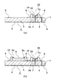
次に、図1に示した高周波回路基板20の製造方法について図3を用いて説明する。図3において、図1と同一もしくは同等の部分には同じ記号を付し、その説明を省略する。
【0028】
まず、第1の工程において、図3(a)に示すように回路基板2の接地電極4とスルーホール7を介して接続されている所定の配線電極6上にフィルタ30を搭載し、その入出力端子部分と回路基板2の配線電極6とをワイヤー10で接続する。その際、フィルタ30の接地電極32は、ハンダ付けや導電性の材料を用いたダイボンディングなどによって配線電極6と電気的に接続され、接地される。フィルタ30の入出力端子部分は、図2に示したように接地電極32と直流的に接続されているため、回路基板2の接地電極4とも直流的に接続されることになる。すなわち、回路基板2の配線電極6のうち、フィルタ30と接続されているものは、フィルタ30を介して接地電極4と直流的に接続されていることになる。
【0029】
次に、第2の工程として、図3(b)に示すように、回路基板2に半導体素子8を搭載し、その接続ランドと回路基板2の配線電極6とをワイヤー10で接続する。半導体素子8の接続ランドとしては、外部との間で高周波信号の伝達される高周波信号端子となる接続ランド8aと、電源端子のような高周波信号の伝達されないその他の端子となる接続ランド8bとを有する。そして、半導体素子8の高周波信号端子である接続ランド8aはフィルタ30と接続されている配線電極6と接続されている。このとき、第1の工程で説明したように、フィルタ30と接続されている配線電極6は接地電極4と直流的に接続されているため、例えば半導体素子8を搭載する工程において何らかの原因で端子電極5に静電気によるサージ電圧が印加されても、サージ電圧が半導体素子8に達する前にフィルタ30を介して接地されてしまうために、半導体素子8に印加されて半導体素子8が静電破壊を起こすことはない。そのため、静電気対策のレベルを下げることができ、工程管理のコストを低減することができる。
【0030】
なお、実際の工程としては、第ボンディングの工程とワイヤーボンディングの工程をまとめるために、第1の工程におけるフィルタ30の入出力端子部分と回路基板2の配線電極6とをワイヤー10で接続する部分は、第2の工程における回路基板2に半導体素子8を搭載する部分と、半導体素子8の接続ランドと回路基板2の配線電極6とをワイヤー10で接続する部分の間に実施することになる。その場合でも、半導体素子8の接続ランドと回路基板2の配線電極6とをワイヤー10で接続するときには、フィルタ30の搭載が完了しているため、回路基板2の配線電極6のうち、フィルタ30と接続されているものは、フィルタ30を介して接地電極4と直流的に接続されていることになる。そのため、静電気対策としては、半導体素子8の搭載の前にフィルタ30のワイヤーボンディングを行う場合と全く同じ作用効果を奏するものである。
【0031】
図1に戻り、このように構成された高周波回路基板20においては、回路基板2の端子電極5と、端子電極5との間で高周波信号が伝達される半導体素子8の高周波信号端子である接続ランド8aの両方が、フィルタ30を介して回路基板2の接地電極4と直流的に接続されているために耐圧が高く、何らかの原因で端子電極5に静電気によるサージ電圧が印加されても、半導体素子が静電破壊を起こすことは少ない。したがって、高周波回路基板20の信頼性を向上させることができる。また、ストリップ線路電極を回路基板2を構成する誘電体基板3より誘電率の高い誘電体基板31上に形成してフィルタ30の小型化を図っているため、高周波回路基板20自身の大幅な小型化を図ることができる。
【0032】
ここで、図4に、本発明の高周波回路基板に用いる受動インピーダンス回路素子であるフィルタの別の実施例を示す。図4において、図2と同一もしくは同等の部分には同じ記号を付し、その説明を省略する。
【0033】
図4において、フィルタ35は、誘電体基板31の他方主面上に直線状で約1/2波長のストリップ線路電極36を有し、その中央部分がスルーホール34を介して接地電極32と接続されている。ストリップ線路電極36の両側端部から少し中央側に寄った位置、すなわち入力端子や出力端子となる部分にはワイヤー10が接続されている。
【0034】
このように構成されたフィルタ35においては、ストリップ線路電極36の一端側と他端側がそれぞれ1/4波長の共振器として動作するとともに、2つの共振器がスルーホール34の有するインダクタンス成分を介して結合して特定の周波数を通過させるバンドパスフィルタとして機能する。また、ストリップ線路電極36の中央部がスルーホール34を介して接地電極32と接続されているため、フィルタ35の入出力端子部分(入出力用のワイヤーが接続される部分)は接地電極32と直流的に接続されている。
【0035】
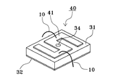
図5に、本発明の高周波回路基板に用いる受動インピーダンス回路素子であるフィルタのさらに別の実施例を示す。図5において、図4と同一もしくは同等の部分には同じ記号を付し、その説明を省略する。
【0036】
図5において、フィルタ40は、直線状のストリップ線路電極36に代えてS字上のストリップ線路電極41を有する点でのみフィルタ35と異なる。
【0037】
このように構成されたフィルタ40においては、ストリップ線路電極41の各部が相互に結合し合うことによって、スプリアス特性の低減などのフィルタ特性上の改善に加えて、フィルタ35よりもさらに小型化を図ることができる。
【0038】
図4、5に示したフィルタ35、40においても、図2に示したフィルタ30と同様に入出力端子部分が接地電極と直流的に接続されているため、高周波回路基板に搭載された場合にはフィルタ30と同様の作用効果を奏することができる。
【0039】
図6に、本発明の高周波回路基板の別の実施例の断面図を示す。図6において、図1と同一もしくは同等の部分には同じ記号を付し、その説明を省略する。
【0040】
図6に示した高周波回路基板50は、誘電体基板3の他方主面に形成された配線電極6上に半導体素子8と受動インピーダンス回路素子であるフィルタ30をバンプ実装(フリップチップ実装)で搭載して構成されている。ここで、半導体素子8の端子8a、8b上にはバンプ8cが設けられており、バンプ8cを介して配線電極6と接続されている。また、フィルタ30にもストリップ線路電極33上にバンプ30aが設けられており、このバンプ30aを介して配線電極6と接続されている。そのため、図1に示した高周波回路基板20のようなワイヤー(ボンディングワイヤー)は存在しない。
【0041】
このように、高周波回路基板50においては、半導体素子8とフィルタ30をバンプ実装することによってワイヤーボンディングの工程を省くことができるため、静電破壊の可能性をさらに低くすることができる。
【0042】
図7に、本発明の高周波回路基板に搭載される半導体素子の別の実施例の平面図を示す。図7において、半導体素子60は、半導体チップ61上に各種回路素子(図示せず)とともにそれらに接続された接続ランド62、63、64、65が形成されている。このうち、接続ランド62は電源入力用端子、接続ランド63は接地用端子、接続ランド64、65は高周波信号端子である。そして、高周波信号端子以外の端子である接続ランド62と接続ランド63の間には静電気保護用ダイオード66が形成されている。
【0043】
このように、高周波信号端子以外の端子である接続ランド62、63に静電気保護用ダイオードを設けることによって、半導体素子60の高周波信号端子以外の端子に印加されるサージ電圧に対する耐圧を高くすることがができる。しかも、高周波信号端子である接続ランド64、65には静電気保護用ダイオードが設けられていないため、ダイオードによる高周波信号のロスが発生することもない。そして、このように構成された半導体素子を本発明の高周波回路基板に搭載することによって、高周波信号が伝達される経路以外の経路を介してサージ電圧が印加された場合の半導体素子の静電破壊の可能性を低下させることができる。
【0044】
なお、上記の各実施例の高周波回路基板においては、受動インピーダンス回路素子としてフィルタを用いているが、受動インピーダンス回路素子としては積極的なフィルタ特性を有していない例えば整合回路などでも構わないもので、フィルタの場合と同様の作用効果を奏するものである。
【0045】
図8に、本発明の高周波モジュールの一実施例を示す。図8において、図1と同一もしくは同等の部分には同じ記号を付し、その説明を省略する。また、図9に、高周波モジュールが無線通信の送受信モジュールである場合の1つの例の概略ブロック図を示す。
【0046】
図8において、高周波モジュール70は、高周波回路基板20に、半導体素子8やフィルタ30を覆うカバー71を搭載して構成されている。この場合、高周波回路基板20の端子電極5は外部端子になる。
【0047】
また、ブロック図としては図9に示すように、高周波モジュール70は、局部発振器LOと、高周波高周波スイッチSW1、SW2と、ミキサMIX1、MIX2と、パワーアンプPAと、ローノイズアンプLNAと、フィルタ30から構成されている。このうち、局部発振器LOと、高周波スイッチSW1、SW2と、ミキサMIX1、MIX2と、パワーアンプPAと、ローノイズアンプLNAは半導体素子8に形成されている。
【0048】
ここで、局部発振器LOは高周波スイッチSW1の第1の端子に接続され、高周波スイッチSW1の第2、第3の端子はそれぞれミキサMIX1とミキサMIX2に接続されている。ミキサMIX1はパワーアンプPAを介して高周波スイッチSW2の第2の端子に接続されている。高周波スイッチSW2の第1の端子はフィルタ30を介して高周波モジュール50とは別に設けられているアンテナANTに接続されている。高周波スイッチSW2の第3の端子はローノイズアンプLNAを介してミキサMIX2に接続されている。
【0049】
次に、高周波モジュール70の動作について簡単に説明する。まず、ミキサMIX1には図示を省略した送信側回路からIF信号が入力されている。高周波スイッチSW1の第1の端子が第2の端子と接続されていると、局部発振器LOから出力されたキャリア信号がミキサMIX1に入力されるため、ミキサMIX1からはIF信号で変調されたキャリア信号、すなわちRF信号が出力される。RF信号はパワーアンプPAで増幅され、高周波スイッチSW2の第2の端子に入力される。高周波スイッチSW2は高周波スイッチSW1と連動して、高周波スイッチSW1の第1の端子が第2の端子と接続されるときに高周波スイッチSW2の第1の端子も第2の端子と接続される。そのため、高周波スイッチSW2の第2の端子に入力されたRF信号は第1の端子から出力され、フィルタ30に入力されて不必要な信号が取り除かれ、アンテナANTから電波として放射される。
【0050】
一方、高周波スイッチSW1および高周波スイッチSW2の第1の端子が第3の端子と接続されていると、アンテナANTで受信したRF信号の電波はフィルタ30に入力されて不必要な信号が取り除かれ、高周波スイッチSW2を介してローノイズアンプLNAに入力されて増幅され、ミキサMIX2に入力される。ミキサMIX2には局部発振器LOから出力されたキャリア信号が高周波スイッチSW1を介して入力されているため、ミキサMIX2ではRF信号からキャリア信号の成分が取り除かれ、IF信号として出力され、図示を省略した受信側回路に入力される。
【0051】
このように構成された高周波モジュール70においては、アンテナANTに接続される端子を介して静電気によるサージ電圧が印加される可能性があるが、サージ電圧はフィルタ30を介して回路基板2の接地電極4に流れるため、半導体素子8に含まれている局部発振器LOや、高周波スイッチSW1、SW2や、ミキサMIX1、MIX2や、パワーアンプPAや、ローノイズアンプLNAが静電破壊を起こすのを防止することができる。そのため、静電気対策の十分でない製造ラインなどにおいても取り扱うことが容易となる。
【0052】
図10に、本発明の電子装置の一実施例の斜視図を示す。図10において、電子装置の1つである携帯電話80は、筐体81と、その中に配置されたプリント基板82と、プリント基板82上に実装された本発明の高周波モジュール83を備えている。高周波モジュール83は、例えばアンプや発振器、フィルタなどの高周波部品である。
【0053】
このように構成された携帯電話80においては、本発明の高周波モジュール83を用いているため、静電気に対して強く、製造工程における静電気対策を簡素化できるため、コストダウンと信頼性の向上を図ることができる。
【0054】
なお、図10においては電子装置として携帯電話を示したが、電子装置としては携帯電話に限るものではなく、本発明の高周波モジュールを用いたものであれば何でも構わないものである。
【0055】
【発明の効果】
本発明によれば、接地電極と端子電極を有した回路基板と、回路基板に搭載され且つ端子電極との間で高周波信号が伝達される高周波信号端子を有した半導体素子と、回路基板に搭載され且つ高周波信号端子と端子電極の間に接続されて高周波信号のみを通過させる受動インピーダンス回路素子とを具備する高周波回路基板であって、受動インピーダンス回路素子を、誘電体基板と、誘電体基板の表面に形成され且つその入出力端部において高周波信号端子と端子電極とがそれぞれ接続されたストリップ線路電極とで構成し、ストリップ線路電極を、誘電体基板及び回路基板のいずれか又は双方に設けられたスルーホールを通じて、回路基板の接地電極に接続することによって、静電気によるサージ電圧に対する耐圧を高め、信頼性を向上させることができる。
【0056】
また、受動インピーダンス回路素子における誘電体基板の誘電率を、回路基板および半導体素子を構成する材料の誘電率よりも高く設定することによって、高周波回路基板の小型化を図ることができる。
【0057】
また、本発明の高周波モジュールおよびそれを用いた電子装置によれば、本発明の高周波回路基板を用いることによって、静電気によるサージ電圧に対する耐圧を高め、信頼性を向上させることができる。
【図面の簡単な説明】
【図1】本発明の高周波回路基板の一実施例を示す断面図である。
【図2】本発明の高周波回路基板に搭載されるフィルタの一実施例を示す斜視図である。
【図3】本発明の高周波回路基板の製造工程を示す図で、(a)は回路基板のフィルタが搭載された状態を示し、(b)はあらかじめフィルタを搭載した回路基板に半導体素子が搭載された状態を示す。
【図4】本発明の高周波回路基板に搭載されるフィルタの別の実施例を示す斜視図である。
【図5】本発明の高周波回路基板に搭載されるフィルタのさらに別の実施例を示す斜視図である。
【図6】本発明の高周波回路基板の別の実施例を示す断面図である。
【図7】本発明の高周波回路基板に搭載される半導体素子の別の実施例を示す平面図である。
【図8】本発明の高周波モジュールの一実施例を示す断面図である。
【図9】図8の高周波モジュールの概略ブロック図である。
【図10】本発明の電子装置の一実施例を示す一部破砕斜視図である。
【図11】従来の高周波回路基板を示す断面図である。
【符号の説明】
2…回路基板
3…誘電体基板
4…接地電極
5…端子電極
6…配線電極
7…スルーホール
8、60…半導体素子
8a、64、65…接続ランド(高周波信号端子)
8c、30a…バンプ
10…ワイヤー
20、50…高周波回路基板
30、35、40…フィルタ(受動インピーダンス回路素子)
70…高周波モジュール
71…カバー
80…携帯電話
Claims (6)
- 接地電極と端子電極を有した回路基板と、当該回路基板に搭載され且つ上記端子電極との間で高周波信号が伝達される高周波信号端子を有した半導体素子と、当該回路基板に搭載され且つ上記高周波信号端子と上記端子電極の間に接続されて上記高周波信号のみを通過させる受動インピーダンス回路素子とを具備する高周波回路基板であって、
上記受動インピーダンス回路素子を、誘電体基板と、当該誘電体基板の表面に形成され且つその入出力端部において上記高周波信号端子と端子電極とがそれぞれ接続されたストリップ線路電極とで構成し、
上記ストリップ線路電極を、上記誘電体基板及び上記回路基板のいずれか又は双方に設けられたスルーホールを通じて、上記回路基板の接地電極に接続した、
ことを特徴とする高周波回路基板。 - 上記受動インピーダンス回路素子における誘電体基板の誘電率を、上記回路基板および上記半導体素子を構成する材料の誘電率よりも高く設定した、
ことを特徴とする請求項1に記載の高周波回路基板。 - 上記半導体素子と上記受動インピーダンス回路素子とを上記回路基板上にバンプ実装し、当該バンプを通じて、上記高周波信号端子と端子電極とを当該受動インピーダンス回路素子のストリップ線路電極の入出力端部にそれぞれ接続した、
ことを特徴とする請求項1又は請求項2に記載の高周波回路基板。 - 上記半導体素子は、上記高周波信号端子以外に電源入力用端子と接地用端子とを有し、静電気保護用ダイオードをこれら電源入力用端子と接地用端子との間に接続した、
ことを特徴とする請求項1ないし請求項3のいずれかに記載の高周波回路基板。 - 請求項1ないし請求項4のいずれかに記載の高周波回路基板を備え、上記回路基板を部品搭載基板とし、上記回路基板の上記端子電極を外部端子とした、
ことを特徴とする高周波モジュール。 - 請求項1ないし請求項4のいずれかに記載の高周波回路基板又は請求項5に記載の高周波モジュールを備えた、
ことを特徴とする電子装置。
Priority Applications (4)
| Application Number | Priority Date | Filing Date | Title |
|---|---|---|---|
| JP2000324080A JP3649111B2 (ja) | 2000-10-24 | 2000-10-24 | 高周波回路基板およびそれを用いた高周波モジュールおよびそれを用いた電子装置 |
| US09/974,668 US6847275B2 (en) | 2000-10-24 | 2001-10-10 | High-frequency circuit board unit, high frequency module using the same unit, electronic apparatus using the same module, and manufacturing method for the high-frequency circuit board unit |
| GB0124989A GB2372153B (en) | 2000-10-24 | 2001-10-17 | High frequency circuit board unit, module and electronic apparatus, and method for manufacturing the unit |
| DE10152533A DE10152533B4 (de) | 2000-10-24 | 2001-10-24 | Hochfrequenz-Schaltungsplatineneinheit, Hochfrequenz-Modul, bei dem die Einheit verwendet ist, elektronische Vorrichtung, bei der das Modul verwendet ist, und Verfahren zur Herstellung der Hochfrequenz-Schaltungsplatineneinheit |
Applications Claiming Priority (1)
| Application Number | Priority Date | Filing Date | Title |
|---|---|---|---|
| JP2000324080A JP3649111B2 (ja) | 2000-10-24 | 2000-10-24 | 高周波回路基板およびそれを用いた高周波モジュールおよびそれを用いた電子装置 |
Publications (2)
| Publication Number | Publication Date |
|---|---|
| JP2002134636A JP2002134636A (ja) | 2002-05-10 |
| JP3649111B2 true JP3649111B2 (ja) | 2005-05-18 |
Family
ID=18801668
Family Applications (1)
| Application Number | Title | Priority Date | Filing Date |
|---|---|---|---|
| JP2000324080A Expired - Lifetime JP3649111B2 (ja) | 2000-10-24 | 2000-10-24 | 高周波回路基板およびそれを用いた高周波モジュールおよびそれを用いた電子装置 |
Country Status (4)
| Country | Link |
|---|---|
| US (1) | US6847275B2 (ja) |
| JP (1) | JP3649111B2 (ja) |
| DE (1) | DE10152533B4 (ja) |
| GB (1) | GB2372153B (ja) |
Families Citing this family (57)
| Publication number | Priority date | Publication date | Assignee | Title |
|---|---|---|---|---|
| US6143981A (en) | 1998-06-24 | 2000-11-07 | Amkor Technology, Inc. | Plastic integrated circuit package and method and leadframe for making the package |
| KR100369393B1 (ko) | 2001-03-27 | 2003-02-05 | 앰코 테크놀로지 코리아 주식회사 | 리드프레임 및 이를 이용한 반도체패키지와 그 제조 방법 |
| US6978122B2 (en) * | 2001-05-25 | 2005-12-20 | Kabushiki Kaisha Toshiba | High-frequency switching device incorporating an inverter circuit |
| TW529215B (en) * | 2001-08-24 | 2003-04-21 | Inpaq Technology Co Ltd | IC carrying substrate with an over voltage protection function |
| US6873529B2 (en) * | 2002-02-26 | 2005-03-29 | Kyocera Corporation | High frequency module |
| TWI299559B (en) * | 2002-06-19 | 2008-08-01 | Inpaq Technology Co Ltd | Ic substrate with over voltage protection function and method for manufacturing the same |
| US6936921B2 (en) * | 2002-11-11 | 2005-08-30 | Kyocera Corporation | High-frequency package |
| US6828514B2 (en) * | 2003-01-30 | 2004-12-07 | Endicott Interconnect Technologies, Inc. | High speed circuit board and method for fabrication |
| US6879287B2 (en) * | 2003-05-24 | 2005-04-12 | Agency For Science, Technology And Research | Packaged integrated antenna for circular and linear polarizations |
| US7253517B2 (en) * | 2003-10-28 | 2007-08-07 | Raytheon Company | Method and apparatus for combining multiple integrated circuits |
| JP4020853B2 (ja) * | 2003-11-04 | 2007-12-12 | 沖電気工業株式会社 | アンテナ内蔵半導体装置 |
| JP4335661B2 (ja) * | 2003-12-24 | 2009-09-30 | Necエレクトロニクス株式会社 | 高周波モジュールの製造方法 |
| JP4365750B2 (ja) * | 2004-08-20 | 2009-11-18 | ローム株式会社 | 半導体チップの製造方法、および半導体装置の製造方法 |
| JP4185499B2 (ja) * | 2005-02-18 | 2008-11-26 | 富士通マイクロエレクトロニクス株式会社 | 半導体装置 |
| JP5048230B2 (ja) * | 2005-03-30 | 2012-10-17 | オンセミコンダクター・トレーディング・リミテッド | 半導体装置およびその製造方法 |
| US20060276157A1 (en) * | 2005-06-03 | 2006-12-07 | Chen Zhi N | Apparatus and methods for packaging antennas with integrated circuit chips for millimeter wave applications |
| US7507603B1 (en) | 2005-12-02 | 2009-03-24 | Amkor Technology, Inc. | Etch singulated semiconductor package |
| US7968998B1 (en) | 2006-06-21 | 2011-06-28 | Amkor Technology, Inc. | Side leaded, bottom exposed pad and bottom exposed lead fusion quad flat semiconductor package |
| EP2073264B1 (en) * | 2006-10-02 | 2019-12-11 | Kabushiki Kaisha Toshiba | Semiconductor device |
| US7977774B2 (en) | 2007-07-10 | 2011-07-12 | Amkor Technology, Inc. | Fusion quad flat semiconductor package |
| JP5138338B2 (ja) * | 2007-11-02 | 2013-02-06 | ルネサスエレクトロニクス株式会社 | 半導体パッケージ |
| US7956453B1 (en) | 2008-01-16 | 2011-06-07 | Amkor Technology, Inc. | Semiconductor package with patterning layer and method of making same |
| US7723852B1 (en) | 2008-01-21 | 2010-05-25 | Amkor Technology, Inc. | Stacked semiconductor package and method of making same |
| US8067821B1 (en) | 2008-04-10 | 2011-11-29 | Amkor Technology, Inc. | Flat semiconductor package with half package molding |
| US7768135B1 (en) | 2008-04-17 | 2010-08-03 | Amkor Technology, Inc. | Semiconductor package with fast power-up cycle and method of making same |
| US7808084B1 (en) | 2008-05-06 | 2010-10-05 | Amkor Technology, Inc. | Semiconductor package with half-etched locking features |
| US8125064B1 (en) | 2008-07-28 | 2012-02-28 | Amkor Technology, Inc. | Increased I/O semiconductor package and method of making same |
| US8184453B1 (en) | 2008-07-31 | 2012-05-22 | Amkor Technology, Inc. | Increased capacity semiconductor package |
| JP2010040894A (ja) * | 2008-08-07 | 2010-02-18 | Rohm Co Ltd | 半導体装置および半導体装置の製造方法 |
| US7847392B1 (en) | 2008-09-30 | 2010-12-07 | Amkor Technology, Inc. | Semiconductor device including leadframe with increased I/O |
| US7989933B1 (en) | 2008-10-06 | 2011-08-02 | Amkor Technology, Inc. | Increased I/O leadframe and semiconductor device including same |
| US8008758B1 (en) | 2008-10-27 | 2011-08-30 | Amkor Technology, Inc. | Semiconductor device with increased I/O leadframe |
| US8089145B1 (en) | 2008-11-17 | 2012-01-03 | Amkor Technology, Inc. | Semiconductor device including increased capacity leadframe |
| US8072050B1 (en) | 2008-11-18 | 2011-12-06 | Amkor Technology, Inc. | Semiconductor device with increased I/O leadframe including passive device |
| US7875963B1 (en) | 2008-11-21 | 2011-01-25 | Amkor Technology, Inc. | Semiconductor device including leadframe having power bars and increased I/O |
| US7982298B1 (en) | 2008-12-03 | 2011-07-19 | Amkor Technology, Inc. | Package in package semiconductor device |
| US8487420B1 (en) | 2008-12-08 | 2013-07-16 | Amkor Technology, Inc. | Package in package semiconductor device with film over wire |
| US8680656B1 (en) | 2009-01-05 | 2014-03-25 | Amkor Technology, Inc. | Leadframe structure for concentrated photovoltaic receiver package |
| US20170117214A1 (en) | 2009-01-05 | 2017-04-27 | Amkor Technology, Inc. | Semiconductor device with through-mold via |
| US8058715B1 (en) | 2009-01-09 | 2011-11-15 | Amkor Technology, Inc. | Package in package device for RF transceiver module |
| US8026589B1 (en) | 2009-02-23 | 2011-09-27 | Amkor Technology, Inc. | Reduced profile stackable semiconductor package |
| US7960818B1 (en) | 2009-03-04 | 2011-06-14 | Amkor Technology, Inc. | Conformal shield on punch QFN semiconductor package |
| US8575742B1 (en) | 2009-04-06 | 2013-11-05 | Amkor Technology, Inc. | Semiconductor device with increased I/O leadframe including power bars |
| JP5341717B2 (ja) * | 2009-11-10 | 2013-11-13 | ルネサスエレクトロニクス株式会社 | 半導体パッケージ及びシステム |
| US8502735B1 (en) | 2009-11-18 | 2013-08-06 | Ball Aerospace & Technologies Corp. | Antenna system with integrated circuit package integrated radiators |
| US9078347B2 (en) * | 2010-07-30 | 2015-07-07 | Kyocera Corporation | Electronic component housing unit, electronic module, and electronic device |
| TWI557183B (zh) | 2015-12-16 | 2016-11-11 | 財團法人工業技術研究院 | 矽氧烷組成物、以及包含其之光電裝置 |
| US8648450B1 (en) | 2011-01-27 | 2014-02-11 | Amkor Technology, Inc. | Semiconductor device including leadframe with a combination of leads and lands |
| JP2012222725A (ja) * | 2011-04-13 | 2012-11-12 | Toshiba Corp | アクティブアレイアンテナ装置 |
| US9704725B1 (en) | 2012-03-06 | 2017-07-11 | Amkor Technology, Inc. | Semiconductor device with leadframe configured to facilitate reduced burr formation |
| KR101486790B1 (ko) | 2013-05-02 | 2015-01-28 | 앰코 테크놀로지 코리아 주식회사 | 강성보강부를 갖는 마이크로 리드프레임 |
| KR101563911B1 (ko) | 2013-10-24 | 2015-10-28 | 앰코 테크놀로지 코리아 주식회사 | 반도체 패키지 |
| WO2015062067A1 (en) * | 2013-11-01 | 2015-05-07 | Telefonaktiebolaget L M Ericsson (Publ) | Method and arrangement for board-to-board interconnection |
| US9673122B2 (en) | 2014-05-02 | 2017-06-06 | Amkor Technology, Inc. | Micro lead frame structure having reinforcing portions and method |
| CA2954267C (en) | 2014-05-19 | 2018-08-28 | Loren E. Ralph | System and method for satellite using multifunctional motherboard |
| JP2021048558A (ja) * | 2019-09-20 | 2021-03-25 | 株式会社村田製作所 | 高周波モジュールおよび通信装置 |
| JP7451325B2 (ja) | 2020-06-29 | 2024-03-18 | 株式会社小糸製作所 | 画像投影装置および車両用灯具 |
Family Cites Families (8)
| Publication number | Priority date | Publication date | Assignee | Title |
|---|---|---|---|---|
| JPH06236937A (ja) | 1993-02-10 | 1994-08-23 | Sumitomo Electric Ind Ltd | マイクロ波半導体装置用パッケージ |
| US5510758A (en) | 1993-04-07 | 1996-04-23 | Matsushita Electric Industrial Co., Ltd. | Multilayer microstrip wiring board with a semiconductor device mounted thereon via bumps |
| JP2790033B2 (ja) | 1993-04-07 | 1998-08-27 | 松下電器産業株式会社 | 半導体装置 |
| ATE180575T1 (de) * | 1993-08-09 | 1999-06-15 | Siemens Ag | Dopplerradarmodul in mikrostreifenleitungstechnik |
| JP3120682B2 (ja) * | 1995-01-09 | 2000-12-25 | 株式会社村田製作所 | チップ型フィルタ |
| JP3663898B2 (ja) * | 1997-04-14 | 2005-06-22 | 株式会社村田製作所 | 高周波モジュール |
| US6043727A (en) * | 1998-05-15 | 2000-03-28 | Hughes Electronics Corporation | Reconfigurable millimeterwave filter using stubs and stub extensions selectively coupled using voltage actuated micro-electro-mechanical switches |
| EP1037308A1 (en) * | 1999-03-18 | 2000-09-20 | Telefonaktiebolaget Lm Ericsson | Electric filter for filtering low frequencies |
-
2000
- 2000-10-24 JP JP2000324080A patent/JP3649111B2/ja not_active Expired - Lifetime
-
2001
- 2001-10-10 US US09/974,668 patent/US6847275B2/en not_active Expired - Lifetime
- 2001-10-17 GB GB0124989A patent/GB2372153B/en not_active Expired - Lifetime
- 2001-10-24 DE DE10152533A patent/DE10152533B4/de not_active Expired - Lifetime
Also Published As
| Publication number | Publication date |
|---|---|
| US20020072147A1 (en) | 2002-06-13 |
| DE10152533A1 (de) | 2002-07-04 |
| US6847275B2 (en) | 2005-01-25 |
| GB2372153A (en) | 2002-08-14 |
| GB0124989D0 (en) | 2001-12-05 |
| DE10152533B4 (de) | 2013-02-07 |
| JP2002134636A (ja) | 2002-05-10 |
| GB2372153B (en) | 2005-05-11 |
Similar Documents
| Publication | Publication Date | Title |
|---|---|---|
| JP3649111B2 (ja) | 高周波回路基板およびそれを用いた高周波モジュールおよびそれを用いた電子装置 | |
| US6456172B1 (en) | Multilayered ceramic RF device | |
| US7245884B2 (en) | RF module | |
| US7043285B2 (en) | Wireless terminal with dual band antenna arrangement and RF module for use with dual band antenna arrangement | |
| US6937845B2 (en) | High-frequency module and radio device using the same | |
| US7149496B2 (en) | High-frequency module and radio communication apparatus | |
| US6838956B2 (en) | Packaging methodology for duplexers using FBARs | |
| US8253483B2 (en) | High-frequency switch module | |
| US20020100970A1 (en) | High frequency switch, two-band type high frequency switch, three-band type high frequency switch, and mobile communication equipment | |
| JP4531399B2 (ja) | 送信及び/又は受信モジュール | |
| US20030022638A1 (en) | Electronic apparatus and design method | |
| US6788164B2 (en) | Complex high frequency components | |
| EP1094538A2 (en) | Multilayered ceramic RF device | |
| US20010017576A1 (en) | Isolator device with built-in power amplifier | |
| US20090195334A1 (en) | High frequency module provided with power amplifier | |
| JPH10303640A (ja) | アンテナ装置 | |
| US20030183928A1 (en) | High-frequency switch device and electronic device using the same | |
| JP3976297B2 (ja) | 高周波回路モジュールおよび通信装置 | |
| WO2003038992A1 (fr) | Melangeur d'harmoniques d'ordre pair a filtre integre et appareil de communication radio haute frequence l'utilisant | |
| US6677537B2 (en) | Nonreciprocal circuit device and mounting structure of the same | |
| JP3850325B2 (ja) | マイクロ波集積回路 | |
| KR100839252B1 (ko) | 회로와 개별 전자부품간에 고주파신호를 전달하기 위한 연결 | |
| US20030062962A1 (en) | High-frequency oscillation circuit, high-frequency module, and communication apparatus | |
| JP4399755B2 (ja) | 高周波スイッチモジュール | |
| US20240039136A1 (en) | Filter device and radio-frequency front-end circuit equipped with the same |
Legal Events
| Date | Code | Title | Description |
|---|---|---|---|
| A977 | Report on retrieval |
Free format text: JAPANESE INTERMEDIATE CODE: A971007 Effective date: 20040513 |
|
| A131 | Notification of reasons for refusal |
Free format text: JAPANESE INTERMEDIATE CODE: A131 Effective date: 20041012 |
|
| A521 | Request for written amendment filed |
Free format text: JAPANESE INTERMEDIATE CODE: A523 Effective date: 20041213 |
|
| A521 | Request for written amendment filed |
Free format text: JAPANESE INTERMEDIATE CODE: A523 Effective date: 20041222 |
|
| RD02 | Notification of acceptance of power of attorney |
Free format text: JAPANESE INTERMEDIATE CODE: A7422 Effective date: 20041222 |
|
| TRDD | Decision of grant or rejection written | ||
| A01 | Written decision to grant a patent or to grant a registration (utility model) |
Free format text: JAPANESE INTERMEDIATE CODE: A01 Effective date: 20050125 |
|
| A61 | First payment of annual fees (during grant procedure) |
Free format text: JAPANESE INTERMEDIATE CODE: A61 Effective date: 20050207 |
|
| R150 | Certificate of patent or registration of utility model |
Free format text: JAPANESE INTERMEDIATE CODE: R150 Ref document number: 3649111 Country of ref document: JP Free format text: JAPANESE INTERMEDIATE CODE: R150 |
|
| FPAY | Renewal fee payment (event date is renewal date of database) |
Free format text: PAYMENT UNTIL: 20090225 Year of fee payment: 4 |
|
| FPAY | Renewal fee payment (event date is renewal date of database) |
Free format text: PAYMENT UNTIL: 20090225 Year of fee payment: 4 |
|
| FPAY | Renewal fee payment (event date is renewal date of database) |
Free format text: PAYMENT UNTIL: 20100225 Year of fee payment: 5 |
|
| FPAY | Renewal fee payment (event date is renewal date of database) |
Free format text: PAYMENT UNTIL: 20110225 Year of fee payment: 6 |
|
| FPAY | Renewal fee payment (event date is renewal date of database) |
Free format text: PAYMENT UNTIL: 20110225 Year of fee payment: 6 |
|
| FPAY | Renewal fee payment (event date is renewal date of database) |
Free format text: PAYMENT UNTIL: 20120225 Year of fee payment: 7 |
|
| FPAY | Renewal fee payment (event date is renewal date of database) |
Free format text: PAYMENT UNTIL: 20130225 Year of fee payment: 8 |
|
| EXPY | Cancellation because of completion of term |