JP3633397B2 - Tunnel lining method - Google Patents
Tunnel lining method Download PDFInfo
- Publication number
- JP3633397B2 JP3633397B2 JP26482699A JP26482699A JP3633397B2 JP 3633397 B2 JP3633397 B2 JP 3633397B2 JP 26482699 A JP26482699 A JP 26482699A JP 26482699 A JP26482699 A JP 26482699A JP 3633397 B2 JP3633397 B2 JP 3633397B2
- Authority
- JP
- Japan
- Prior art keywords
- formwork
- panel
- concrete
- lining method
- tunnel
- Prior art date
- Legal status (The legal status is an assumption and is not a legal conclusion. Google has not performed a legal analysis and makes no representation as to the accuracy of the status listed.)
- Expired - Fee Related
Links
- 238000000034 method Methods 0.000 title claims description 29
- 239000004567 concrete Substances 0.000 claims description 39
- 238000009415 formwork Methods 0.000 claims description 36
- 238000009412 basement excavation Methods 0.000 claims description 17
- 239000011178 precast concrete Substances 0.000 claims description 14
- 239000012779 reinforcing material Substances 0.000 claims description 10
- 230000003014 reinforcing effect Effects 0.000 description 17
- 238000010276 construction Methods 0.000 description 10
- 238000009434 installation Methods 0.000 description 7
- 230000002787 reinforcement Effects 0.000 description 7
- 229910000831 Steel Inorganic materials 0.000 description 6
- 239000010959 steel Substances 0.000 description 6
- 239000003351 stiffener Substances 0.000 description 4
- 230000008878 coupling Effects 0.000 description 3
- 238000010168 coupling process Methods 0.000 description 3
- 238000005859 coupling reaction Methods 0.000 description 3
- 230000000694 effects Effects 0.000 description 3
- 238000004904 shortening Methods 0.000 description 3
- 230000002093 peripheral effect Effects 0.000 description 2
- 230000015556 catabolic process Effects 0.000 description 1
- 239000002184 metal Substances 0.000 description 1
- 230000002035 prolonged effect Effects 0.000 description 1
- 238000005507 spraying Methods 0.000 description 1
Images


Landscapes
- Lining And Supports For Tunnels (AREA)
Description
【0001】
【発明の属する技術分野】
この発明は、トンネル覆工工法に関し、特に、型枠兼用のパネルを用いるトンネル覆工工法に関するものである。
【0002】
【従来の技術】
山岳トンネルを構築する際には、掘削された断面に覆工コンクリート層を形成することが行われていて、このような覆工コンクリート層は、一般的に、吹付けにより一次覆工を行った後に、二次覆工が行われる。
【0003】
二次覆工では、掘削面の内面側に、型枠板を設置して、掘削面と型枠板との間にコンクリートを打設する型枠を用いる工法が知られている。
【0004】
型枠を用いる二次覆工工法では、セントルと呼ばれる幅が約10m程度の移動式の型枠を用いる方式が知られている。この種の覆工工法に用いられるセントルは、トンネル全断面の大きさをカバーできる型枠板を、移動式の支持架台に組付け支持させた構造になっていて、これを坑外で組み立てた状態で、坑内に引き込み、掘削面と型枠板との間にコンクリートを打設して、覆工コンクリート層を形成した後に、順次トンネル軸方向に沿って移動させて施工を行う。
【0005】
しかしながら、このようなセントル方式の覆工工法には、以下に説明する技術的な課題があった。
【0006】
【発明が解決しようとする課題】
すなわち、トンネルを構築する際には、内部の一部分を拡幅する場合があるが、このような場合に前記セントル方式の覆工工法を採用すると、拡幅部の断面が、他の部分の断面に比べて大きいので、予め坑外でセントルを組立てると、坑内に引き込むことができないので、拡幅部の施工現場でセントルを組むことになる。
【0007】
ところが、坑内でセントルを組む作業は、クレーンの吊り代ろを確保することができないので、人力に頼らざるを得ず、この作業が煩雑で危険を伴なうこともあって、工期が長期化する大きな要因となっていた。
【0008】
本発明は、このような従来の問題点に鑑みてなされたものであって、坑内でセントルを組んで施工する場合よりも、大幅に工期を短縮することができるトンネル覆工工法を提供することにある。
【0009】
【課題を解決するための手段】
上記目的を達成するために、本発明は、掘削面の内周に沿って所定の間隔を隔てて型枠を設置し、前記掘削面と型枠との間にコンクリートを打設して覆工コンクリート層を形成するトンネル覆工工法において、前記型枠は、前記覆工コンクリート層の表面に残置される型枠板兼用のパネルと、このパネルの内面または外面に添設された連結用補強材とを備え、前記型枠を前記掘削面に沿って設置する際に、その連結用補強材の下端側を、周方向に隣接設置する他の型枠の連結用補強材と相互に結合させるとともに、各型枠の上端側を、地山または地山に設置された支保工に一端側を連結したアンカーにより支持するようにした。
このように構成したトンネル覆工工法によれば、掘削面の内周に沿って所定の間隔を隔てて設置される型枠は、覆工コンクリート層の表面に残置される型枠板兼用のパネルと、このパネルの内面または外面に添設された連結用補強材とを備え、型枠を掘削面に沿って設置する際に、その連結用補強材の下端側を、周方向に隣接設置する他の型枠の連結用補強材と相互に結合させるとともに、各型枠の上端側を、地山または地山に設置された支保工に一端側を連結したアンカーにより支持するので、型枠を支持する坑内支保工が不要になり、他の作業との干渉を避けることができる。
また、パネルには、坑外で連結用補強材を取付けることができるとともに、連結用補強材を添設することにより大型化が可能になり、大型のパネルを使用することで、型枠の設置作業を迅速に行える。
さらに、本発明では、前記パネルは、予め製作されるプレキャストコンクリート版で構成することができる。
この構成によれば、プレキャストコンクリート版製のパネルは、型枠板を兼用し、覆工コンクリート層の表面に残置されるので、コンクリート打設後の養生を必要とせず、これにより工期を短縮できる。
また、覆工コンクリート層の表面は、高品質に工場生産することができるプレキャストコンクリート版製のパネルで覆われるため、美観に優れ、耐久性も優れたものとなる。
また、本発明では、前記パネルは、平板状に形成することができる。
この構成によれば、パネルを容易に製作することができる。
【0010】
【発明の実施の形態】
以下、本発明の好適な実施の形態について、添付図面に基づいて詳細に説明する。図1から図3は、本発明にかかるトンネル覆工工法の第1実施例を示している。
【0011】
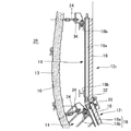
同図に示したトンネル覆工工法では、図1に施工状態の全体正面図を示すように、掘削面10の内周面に沿って所定の間隔を隔てて型枠12を設置し、掘削面10と型枠12との間にコンクリートを打設して覆工コンクリート層14を形成することを基本構成としている。
【0012】
掘削面10の内周側には、その湾曲に沿うようにしてアーチ状の鋼製支保工11が設けられ、この支保工11を埋設するようにして、一次覆工コンクリート層13が吹付け形成されている。
【0013】
本実施例のトンネル覆工工法では、型枠12は、同一構造の複数枚から構成され、各型枠12は、覆工コンクリート層14の表面側に残置される型枠板兼用のプレキャストコンクリート版製の平板パネル16と、この平板パネル16の内面(覆工コンクリートを打設する側)に添設された連結用補強材18とを備えている。
【0014】
プレキャストコンクリート版製の平板パネル16は、予め、坑外の製造プラントで工場生産されるものであって、製作された平板パネル16には、連結用補強材18が坑外で添設固定される。
【0015】
連結用補強材18は、H型鋼からなる縦および横補強材18a,18bを有していて、この縦および横補強材18a,18bが平板パネル16の裏面側に所定の間隔を隔てて格子状に配置されている。
【0016】
平板パネル16の裏面側に連結用補強材18を添設固定すると、平板パネル16の面積を大きくすることが可能になり、大面積の大型化された平板パネル16を使用すると、掘削面10を覆うパネル16の数が低減され、その分だけ設置および組立て作業が容易かつ迅速に行える。
【0017】
掘削面10の内周に沿って型枠12を設置する際には、図1に示すように、周方向の両端に位置する一対の型枠121の下端側が、まず、トンネルのインバート部20上に、予め立ち上げ形成される側壁コンクリート部22に載置される。
【0018】
この端部側の型枠121の設置が終了すると、その上部側に別の型枠122が隣接するようにして連結設置される。型枠122を設置する際には、その下端側を周方向に隣接する型枠121の上端側と結合させるとともに、上端側をアンカー24により支持する。
【0019】
アンカー24は、型枠12を設置する前に既に設置されていて、一端側が地山26中に定着されている。型枠122の設置終了すると、その上部側に同じ方法により順次他の型枠123以降が、トンネルの中心側を向かうようにして連結設置される。
【0020】
そして、トンネル断面の中心軸上に一端が位置する型枠126を設置する際には、天井部に鋼製枠27を設置して、その上部側が鋼製枠27に係止される。鋼製枠27は、型枠126の設置後に、トンネル軸上の天井部に設置されるものであって、コンクリート注入口28が設けられている。このコンクリート注入口28は、型枠126内にコンクリートを打設する際に用いられる。
【0021】
周方向に隣接設置される型枠121と同122のより具体的な連結設置状態の詳細を図2,3に示している。既設の型枠121に別の型枠122を連結設置する際には、まず、型枠122の縦補強材18aの下端側を、既設型枠121の縦補強材18aの上端側と、連結プレート30を両者間にボルトナットで固定して連結する。
【0022】
このとき、型枠121と同122の平板パネル16間に、打設するコンクリートの漏れ防止用のシールガスケット32を介装する。一方、型枠122の上部側は、一端が地山26に定着されたアンカー24の頭部側を、結合ブラケット34を介して、上部側の横補強材18bと結合することにより支持する。アンカー24は、長ナットなどを用いることで、その長さが調整される。
【0023】
以上のようにして型枠12の設置が終了すると、トンネル軸方向の妻側に漏れ止め対策を施した後に、型枠122の平板パネル16の上端側から、例えば、高流動コンクリートを型枠122と掘削面10との間に打設して、表面側にプレキャストコンクリート版製の平板パネル16を残置させた覆工コンクリート層14を形成する。
【0024】
そして、同様な作業を順次トンネル中心軸側まで行うことにより、プレキャストコンクリート版製の平板パネル16の長さに対応した覆工コンクリート層14が形成され、1サイクルの作業を終了する。
【0025】
さて、以上のように構成したトンネル覆工工法によれば、型枠12を掘削面10に沿って設置する際に、その連結用補強材18の下端側を、周方向に隣接設置する他の型枠12の連結用補強材18と相互に結合させるとともに、各型枠12の上端側を、地山に一端側を定着したアンカー24により支持するので、型枠12を支持する坑内支保工が不要になり、他の作業との干渉を避けることができる。
【0026】
また、平板パネル16は、坑外で連結用補強材18を取付けることができるとともに、連結用補強材18を添設することにより大型化が可能になり、大型のパネルを使用することで、型枠12の設置作業を迅速に行える。
【0027】
さらに、プレキャストコンクリート版製の平板パネル16は、型枠板を兼用し、覆工コンクリート層14の表面に残置されるので、コンクリート打設後の養生を必要とせず、これにより工期を短縮できる。
【0028】
このため、本実施例の覆工工法をトンネルの拡幅部に適用すると、セントル方式よりも大幅に工期を低減させることができるとともに、拡幅部以外の一般部分に適用しても、その効果を有効に発揮させることができる。
【0029】
また、覆工コンクリート層14の表面は、高品質に工場生産することができるプレキャストコンクリート版製の平板パネル16で覆われるため、美観に優れ、耐久性も優れたものとなる。
【0030】
さらに、本実施例の場合には、プレキャストコンクリート版製の平板パネル16の背面側には、格子状に配置された連結用補強材18が突設されて、凹凸状になっているので、コンクリートを打設すると、コンクリートと平板パネル16との間の接合面積が大きくなり、両者間の付着強度を増加させる。
【0031】
図4は、本発明にかかるトンネル覆工工法の第2実施例を示しており、上記第1実施例と同一若しくは相当する部分には、同一符号を付してその説明を省略するとともに、異化にその特徴点についてのみ説明する。
【0032】
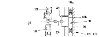
同図に示した実施例では、各型枠12は、上記実施例と同様に、型枠板兼用のプレキャストコンクリート版製の平板パネル16と、連結用補強材18とを備えているが、本実施例の場合には、連結用補強材18は、平板パネル16の外面(覆工コンクリートを打設する側と反対側の面)に添設されている。
【0033】
また、平板パネル16の内面側には、打設されるコンクリートとの間の付着力を補強する複数のジベル36が突設されている。本実施例の場合にも、既設の型枠121に別の型枠122を連結設置する際には、まず、型枠122の縦補強材18aの下端側を、既設型枠121の縦補強材18aの上端側と連結し、型枠122の上部側は、アンカー24により支持する。
【0034】
このとき、本実施例の場合には、平板パネル16の外面側に連結用補強材18が添設されているので、別の部材を介在させることなく、型枠122の縦補強材18aの下端側を、既設型枠121の縦補強材18aの上端側に、ボルトナットを用いて直接連結することができる。
【0035】
また、本実施例の場合には、アンカー24の一端は、地山26に接触するように設置された支保工11に先付けプレート38を介して定着され、他端側は、平板パネル16および縦補強材18aを貫通して、その外方まで延設され、横補強材18bにナットを装着することにより定着されている。
【0036】
この実施例においても、型枠12の設置が終了すると、掘削面10と型枠12との間にコンクリートが打設され、上記実施例と同様に覆工コンクリート層14が形成される。
【0037】
このような型枠12を用いる第2実施例においても第1実施例と同等の作用効果が得られるとともに、特に、第2実施例の場合には、補強材18同志を直接連結することができ、また、例えば、連結用補強材18を平板パネル16から離脱可能に構成しておくと、打設したコンクリートが硬化した後に、これを取り外して転用することも可能なので、第1実施例の場合よりも、構造が簡単で経済的な面でも有利になる。
【0038】
なお、上記実施例では、パネル16をプレキャストコンクリート版で構成し、かつ、その形状を平板としているが、本発明の実施は、これに限られることはなく、例えば、鋼鈑パネルであっても良いし、また、例えば、トンネルの掘削面に沿った湾曲形状のパネルを用いることもできる。
【0039】
【発明の効果】
以上、詳細に説明したように、本発明にかかるトンネル覆工工法によれば、坑内でセントルを組んで施工する場合よりも、大幅に工期を短縮することができる。
【図面の簡単な説明】
【図1】本発明にかかるトンネル覆工工法の一実施例を示す施工状態の正面図である。
【図2】図1の要部拡大図である。
【図3】図2の上面図である。
【図4】本発明にかかるトンネル覆工工法の他の実施例を示す要部説明図である。
【符号の説明】
10 掘削面
11 支保工
12 型枠
14 覆工コンクリート層
16 プレキャストコンクリート平板パネル
18 連結用補強材
24 アンカー[0001]
BACKGROUND OF THE INVENTION
The present invention relates to a tunnel lining method, and more particularly to a tunnel lining method using a panel also serving as a formwork.
[0002]
[Prior art]
When constructing a mountain tunnel, a lining concrete layer is formed on the excavated cross section, and such a lining concrete layer is generally subjected to primary lining by spraying. Later, secondary lining is performed.
[0003]
In secondary lining, a method is known in which a formwork plate is installed on the inner surface side of the excavation surface, and a formwork is used in which concrete is placed between the excavation surface and the formwork plate.
[0004]
In the secondary lining method using a mold, a method using a movable mold called a centle and having a width of about 10 m is known. The centle used in this type of lining method has a structure in which a formwork plate that can cover the size of the entire cross section of the tunnel is assembled and supported on a movable support frame, and this is assembled outside the mine. In this state, the concrete is drawn into the mine, and concrete is placed between the excavation surface and the formwork plate to form a lining concrete layer, and then the construction is carried out by moving along the tunnel axis direction sequentially.
[0005]
However, such a centle-type lining method has the following technical problems.
[0006]
[Problems to be solved by the invention]
That is, when constructing a tunnel, there is a case where a part of the interior is widened, but in such a case, if the centle method lining method is adopted, the cross section of the widened part is compared with the cross section of the other part. Therefore, if the centle is assembled in advance outside the mine, it cannot be pulled into the mine, so the centle is assembled at the construction site of the widened portion.
[0007]
However, when constructing a centre in the mine, it is impossible to secure the crane's lifting allowance, so it is necessary to rely on human power, which can be complicated and dangerous, and the construction period is prolonged. It was a major factor.
[0008]
The present invention has been made in view of such a conventional problem, and provides a tunnel lining method capable of significantly shortening the construction period compared to the case of constructing a centle in a mine. It is in.
[0009]
[Means for Solving the Problems]
In order to achieve the above object, the present invention provides a method of installing a formwork at a predetermined interval along the inner periphery of a digging surface, and placing concrete between the digging surface and the formwork for lining. In the tunnel lining method for forming a concrete layer, the formwork includes a panel that also serves as a formwork plate that is left on the surface of the lining concrete layer, and a connecting reinforcing material that is attached to the inner or outer surface of the panel. When the mold is installed along the excavation surface, the lower end side of the connecting reinforcing material is mutually coupled with the connecting reinforcing material of another mold that is adjacently installed in the circumferential direction. The upper end side of each mold is supported by an anchor having one end connected to a natural ground or a supporting work installed on the natural ground.
According to the tunnel lining method constructed in this way, the formwork installed at a predetermined interval along the inner circumference of the excavation surface is a panel that also serves as a formwork plate left on the surface of the lining concrete layer. And a connecting reinforcing member attached to the inner or outer surface of the panel, and when the formwork is installed along the excavation surface, the lower end side of the connecting reinforcing member is adjacently installed in the circumferential direction. It is combined with the connecting reinforcements of other molds, and the upper end side of each formwork is supported by anchors connected at one end to the ground or the support installed on the ground. Supporting underground support is not required, and interference with other operations can be avoided.
In addition, the panel can be attached with a connecting reinforcement outside the mine, and can be enlarged by attaching a connecting reinforcing material. By using a large panel, it is possible to install a formwork. Work can be done quickly.
Furthermore, in the present invention, the panel can be composed of a precast concrete plate manufactured in advance.
According to this configuration, the precast concrete panel is also used as a form plate and is left on the surface of the lining concrete layer, so no curing is required after placing concrete, thereby shortening the construction period. .
Moreover, since the surface of the lining concrete layer is covered with a panel made of a precast concrete plate that can be produced in a factory with high quality, it has excellent aesthetics and excellent durability.
In the present invention, the panel can be formed in a flat plate shape.
According to this configuration, the panel can be easily manufactured.
[0010]
DETAILED DESCRIPTION OF THE INVENTION
DESCRIPTION OF EXEMPLARY EMBODIMENTS Hereinafter, preferred embodiments of the invention will be described in detail with reference to the accompanying drawings. 1 to 3 show a first embodiment of a tunnel lining method according to the present invention.
[0011]
In the tunnel lining method shown in the figure, as shown in FIG. 1 as an overall front view of the construction state, the
[0012]
On the inner peripheral side of the
[0013]
In the tunnel lining method of the present embodiment, the
[0014]
The
[0015]
The connecting reinforcing
[0016]
When the connecting reinforcing
[0017]
When installing the
[0018]
When installation of the
[0019]
The
[0020]
Then, when installing the
[0021]
The
[0022]
At this time, between the
[0023]
When the installation of the
[0024]
Then, by performing the same operation sequentially to the tunnel central axis side, the lining
[0025]
Now, according to the tunnel lining method constructed as described above, when the
[0026]
Further, the
[0027]
Further, the
[0028]
For this reason, when the lining method of this embodiment is applied to the widened portion of the tunnel, the construction period can be significantly reduced compared to the centle method, and the effect is effective even when applied to general portions other than the widened portion. Can be demonstrated.
[0029]
Moreover, since the surface of the lining
[0030]
Furthermore, in the case of the present embodiment, the connecting reinforcing
[0031]
FIG. 4 shows a second embodiment of the tunnel lining method according to the present invention. The same or corresponding parts as those in the first embodiment are designated by the same reference numerals, the description thereof is omitted, and catabolism is performed. Only the feature points will be described.
[0032]
In the embodiment shown in the figure, each
[0033]
Further, on the inner surface side of the
[0034]
At this time, in the case of the embodiment, since the connecting
[0035]
In the case of the present embodiment, one end of the
[0036]
Also in this embodiment, when the installation of the
[0037]
In the second embodiment using such a
[0038]
In addition, in the said Example, although the
[0039]
【The invention's effect】
As described above in detail, according to the tunnel lining method according to the present invention, the construction period can be greatly shortened as compared with the case of constructing a centle in the mine.
[Brief description of the drawings]
FIG. 1 is a front view of a construction state showing an embodiment of a tunnel lining method according to the present invention.
FIG. 2 is an enlarged view of a main part of FIG.
FIG. 3 is a top view of FIG. 2;
FIG. 4 is a main part explanatory view showing another embodiment of the tunnel lining method according to the present invention.
[Explanation of symbols]
DESCRIPTION OF
Claims (3)
前記型枠は、前記覆工コンクリート層の表面に残置される型枠板兼用のパネルと、このパネルの内面または外面に添設された連結用補強材とを備え、
前記型枠を前記掘削面に沿って設置する際に、その連結用補強材の下端側を、周方向に隣接設置する他の型枠の連結用補強材と相互に結合させるとともに、各型枠の上端側を、地山または地山に設置された支保工に一端側を連結したアンカーにより支持することを特徴とするトンネル覆工工法。In the tunnel lining method in which a mold frame is installed at a predetermined interval along the inner circumference of the excavation surface, and concrete is placed between the excavation surface and the mold frame to form a lining concrete layer,
The formwork includes a panel that also serves as a formwork plate that is left on the surface of the lining concrete layer, and a connecting reinforcing material that is attached to the inner surface or the outer surface of the panel,
When installing the formwork along the excavation surface, the lower end side of the connecting reinforcing material is mutually coupled with the connecting reinforcing material of another formwork adjacently installed in the circumferential direction. A tunnel lining method characterized by supporting the upper end side of the ground by an anchor having one end connected to a natural ground or a supporting work installed on the natural ground.
Priority Applications (1)
| Application Number | Priority Date | Filing Date | Title |
|---|---|---|---|
| JP26482699A JP3633397B2 (en) | 1999-09-20 | 1999-09-20 | Tunnel lining method |
Applications Claiming Priority (1)
| Application Number | Priority Date | Filing Date | Title |
|---|---|---|---|
| JP26482699A JP3633397B2 (en) | 1999-09-20 | 1999-09-20 | Tunnel lining method |
Publications (2)
| Publication Number | Publication Date |
|---|---|
| JP2001090487A JP2001090487A (en) | 2001-04-03 |
| JP3633397B2 true JP3633397B2 (en) | 2005-03-30 |
Family
ID=17408754
Family Applications (1)
| Application Number | Title | Priority Date | Filing Date |
|---|---|---|---|
| JP26482699A Expired - Fee Related JP3633397B2 (en) | 1999-09-20 | 1999-09-20 | Tunnel lining method |
Country Status (1)
| Country | Link |
|---|---|
| JP (1) | JP3633397B2 (en) |
Families Citing this family (4)
| Publication number | Priority date | Publication date | Assignee | Title |
|---|---|---|---|---|
| CN102337903B (en) * | 2011-08-25 | 2013-10-23 | 安徽理工大学 | Method of active coupling support in time and space for control of minimum deformation of surrounding rock of deep well roadway |
| JP7288301B2 (en) * | 2018-12-27 | 2023-06-07 | 日鉄建材株式会社 | Underground structure construction method and underground structure |
| JP7409849B2 (en) * | 2019-12-06 | 2024-01-09 | 株式会社奥村組 | Reinforcement structure of existing tunnel |
| JP7444763B2 (en) * | 2020-12-01 | 2024-03-06 | 大成建設株式会社 | Tunnel lining structure and tunnel construction method |
-
1999
- 1999-09-20 JP JP26482699A patent/JP3633397B2/en not_active Expired - Fee Related
Also Published As
| Publication number | Publication date |
|---|---|
| JP2001090487A (en) | 2001-04-03 |
Similar Documents
| Publication | Publication Date | Title |
|---|---|---|
| CN106869172B (en) | In-situ deposited prefabricated split-mounting type subway underground station construction method | |
| CN111395351B (en) | Assembled supporting structure of foundation pit and supporting construction method | |
| CN113294171B (en) | Prefabricated tunnel lining structure combined with corrugated steel plate and UHPC and its construction method | |
| JP3321697B2 (en) | Tunnel lining method using composite panels | |
| JP4164857B2 (en) | Reconstruction method using existing underground structure | |
| CN211900641U (en) | Buckling-restrained assembled tunnel composite structure supporting system | |
| CN111219200B (en) | Buckling-restrained assembled tunnel combined structure supporting system and construction method thereof | |
| CN107558483B (en) | A kind of construction method of building foundation that installing wallboard | |
| JP2956506B2 (en) | Subway station structure and construction method | |
| JP3633397B2 (en) | Tunnel lining method | |
| JPH09268583A (en) | Structural steel embedded half precast concrete member and construction method of underground structure using the same member | |
| JP3011169B2 (en) | Shield tunnel and lining method | |
| CN111287764A (en) | Tunnel secondary lining structure and construction method thereof | |
| CN109610707A (en) | A design and rapid construction method for flush assembly of prefabricated steel beams and floor slabs | |
| JPH07103785B2 (en) | Segment that does not require joint bolts | |
| JPH04306398A (en) | Repairing method of concrete wall surface | |
| JP2004011327A (en) | Caisson and caisson construction method | |
| KR20060096706A (en) | Deck suspension type underground structure reverse casting method | |
| JP2562156Y2 (en) | Shielding segment with hollow section for filling | |
| JP4104777B2 (en) | Shield tunnel opening method | |
| CN220469099U (en) | Multilayer crossed reinforced concrete V-shaped cylindrical structure | |
| CN219412672U (en) | Prefabricated flue box culvert, integral assembly type flue structure and shield tunnel | |
| CN220909706U (en) | Prefabricated segment and interface structure of underground passage | |
| CN222668202U (en) | Reinforcing structure of tunnel portal and lining structure of tunnel portal | |
| KR200390421Y1 (en) | Top-down substructure by deck suspension |
Legal Events
| Date | Code | Title | Description |
|---|---|---|---|
| A977 | Report on retrieval |
Free format text: JAPANESE INTERMEDIATE CODE: A971007 Effective date: 20041129 |
|
| TRDD | Decision of grant or rejection written | ||
| A01 | Written decision to grant a patent or to grant a registration (utility model) |
Free format text: JAPANESE INTERMEDIATE CODE: A01 Effective date: 20041207 |
|
| A61 | First payment of annual fees (during grant procedure) |
Free format text: JAPANESE INTERMEDIATE CODE: A61 Effective date: 20041220 |
|
| R150 | Certificate of patent or registration of utility model |
Free format text: JAPANESE INTERMEDIATE CODE: R150 |
|
| FPAY | Renewal fee payment (event date is renewal date of database) |
Free format text: PAYMENT UNTIL: 20080107 Year of fee payment: 3 |
|
| FPAY | Renewal fee payment (event date is renewal date of database) |
Free format text: PAYMENT UNTIL: 20090107 Year of fee payment: 4 |
|
| FPAY | Renewal fee payment (event date is renewal date of database) |
Free format text: PAYMENT UNTIL: 20100107 Year of fee payment: 5 |
|
| FPAY | Renewal fee payment (event date is renewal date of database) |
Free format text: PAYMENT UNTIL: 20100107 Year of fee payment: 5 |
|
| FPAY | Renewal fee payment (event date is renewal date of database) |
Free format text: PAYMENT UNTIL: 20110107 Year of fee payment: 6 |
|
| S531 | Written request for registration of change of domicile |
Free format text: JAPANESE INTERMEDIATE CODE: R313531 |
|
| FPAY | Renewal fee payment (event date is renewal date of database) |
Free format text: PAYMENT UNTIL: 20110107 Year of fee payment: 6 |
|
| R350 | Written notification of registration of transfer |
Free format text: JAPANESE INTERMEDIATE CODE: R350 |
|
| FPAY | Renewal fee payment (event date is renewal date of database) |
Free format text: PAYMENT UNTIL: 20120107 Year of fee payment: 7 |
|
| FPAY | Renewal fee payment (event date is renewal date of database) |
Free format text: PAYMENT UNTIL: 20130107 Year of fee payment: 8 |
|
| FPAY | Renewal fee payment (event date is renewal date of database) |
Free format text: PAYMENT UNTIL: 20130107 Year of fee payment: 8 |
|
| FPAY | Renewal fee payment (event date is renewal date of database) |
Free format text: PAYMENT UNTIL: 20140107 Year of fee payment: 9 |
|
| LAPS | Cancellation because of no payment of annual fees |