JP3629897B2 - Permanent magnet synchronous motor - Google Patents
Permanent magnet synchronous motor Download PDFInfo
- Publication number
- JP3629897B2 JP3629897B2 JP17000297A JP17000297A JP3629897B2 JP 3629897 B2 JP3629897 B2 JP 3629897B2 JP 17000297 A JP17000297 A JP 17000297A JP 17000297 A JP17000297 A JP 17000297A JP 3629897 B2 JP3629897 B2 JP 3629897B2
- Authority
- JP
- Japan
- Prior art keywords
- permanent magnet
- synchronous motor
- inter
- rotor
- magnetic
- Prior art date
- Legal status (The legal status is an assumption and is not a legal conclusion. Google has not performed a legal analysis and makes no representation as to the accuracy of the status listed.)
- Expired - Fee Related
Links
Images


Landscapes
- Iron Core Of Rotating Electric Machines (AREA)
- Permanent Magnet Type Synchronous Machine (AREA)
- Permanent Field Magnets Of Synchronous Machinery (AREA)
Description
【0001】
【発明の属する技術分野】
本発明は、永久磁石式同期電動機に関するものである。
【0002】
【従来の技術】
従来、永久磁石式同期電動機は、ロータの磁極となる永久磁石を備え、前記ロータの周囲にステータが配設され、該ステータにロータと対向させて複数のティースが形成されるようになっている。そして、前記ステータに巻装されたコイルに電流を供給すると、該電流によって誘起された磁束により、ステータとロータとの間に反発力及び吸引力が発生させられ、前記反発力及び吸引力によってロータが回転するようになっている。
【0003】
ところが、前記各ティース間にはスロットが形成され、また、前記各永久磁石は互いに分離させて配設されるので、ロータが回転すると、あるティースを通っていた磁束が、隣接するティースを通るようになる。このとき、永久磁石のコーナ部が前記スロットを通過することによって磁束の移動が不連続になる。その結果、磁気リアクタンスの変化に伴ってステータとロータとの間の吸引力が変動し、該変動によってコギングトルクが発生してしまう。
【0004】
そこで、前記各永久磁石間を径方向外方に突出させて突出部を形成するとともに、該各突出部の幅をAとし、スロットピッチをBとしたとき、
A=(n+1/2)×B (nは整数)
の式を満たすように前記突出部の幅A及びスロットピッチBを設定することによって、コギングトルクが発生するのを抑制するようにしたものが提供されている(特開平1−286758号公報参照)。
【0005】
そして、前記ロータの円周方向における各突出部の両端に、前記永久磁石を押さえるための磁石押さえ部が形成されている場合は、該磁石押さえ部を含めた突出部の幅をAとして、前記式を満たすように突出部の幅A及びスロットピッチBを設定するようにしている。
【0006】
【発明が解決しようとする課題】
しかしながら、前記従来の永久磁石式同期電動機においては、突出部の幅A及びスロットピッチBを設定することによってコギングトルクが発生するのを抑制するようにしているので、ティースの幅が異なると、ロータの回転に伴って磁気リアクタンスが変化してしまう。したがって、コギングトルクが発生するのを十分に抑制することができない。
【0007】
本発明は、前記従来の永久磁石式同期電動機の問題点を解決して、コギングトルクが発生するのを十分に抑制することができる永久磁石式同期電動機を提供することを目的とする。
【0008】
【課題を解決するための手段】
そのために、本発明の永久磁石式同期電動機においては、円周方向における複数箇所にティースを備え、該各ティース間にスロットが形成されたステータと、該ステータの径方向内方において回転自在に支持された回転軸と、該回転軸に固定されたロータとから成る。
【0009】
そして、該ロータは、円周方向における複数箇所に埋設された永久磁石、及び該永久磁石を保持し、各永久磁石間に磁極間鉄心を形成するロータコアを備える。
また、磁極間鉄心開角をθとし、前記磁極間鉄心の幅に対応するティースの各端面のうち最も離れた二つの端面の先端と、前記回転軸の中心とを結ぶ2本の直線が成す角度の最小値をθMIN とし、前記磁極間鉄心の幅に対応するティースにおけるティースヘッドの各端部のうち最も離れた二つの端部と、前記回転軸の中心とを結ぶ2本の直線が成す角度を最大値θMAX としたとき、
θMIN ≦θ≦θMAX
となるように前記磁極間鉄心の幅が設定される。
【0010】
【発明の実施の形態】
以下、本発明の実施の形態について図面を参照しながら詳細に説明する。
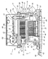
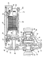
図2は本発明の第1の実施の形態におけるモータ駆動装置の第1の断面図、図3は本発明の第1の実施の形態におけるモータ駆動装置の第2の断面図である。
図において、11はモータアッセンブリ、12は該モータアッセンブリ11の直上に配設されたインバータアッセンブリである。前記モータアッセンブリ11においては、モータケース14内に永久磁石式同期電動機15が収容され、前記インバータアッセンブリ12においては、インバータケース16内にインバータ13、コンデンサ102、制御基板103等が収容される。
【0011】
前記モータケース14は、ほぼ有底の円筒状部分14a、及び該円筒状部分14aの一端を閉鎖して、密閉されたモータ収容室18を形成する蓋(ふた)部分14bから成る。一方、インバータケース16は、中央に配設されたベース16a、該ベース16aと前記円筒状部分14aとの間に配設された中間ケース16b、ブラケット16c、及び前記ベース16aの上にスナップ止めされ、インバータ収容室19を形成するインバータカバー16dから成り、前記中間ケース16b及びブラケット16cは、ボルトb1によって円筒状部分14aに、ボルトb2によってベース16aにそれぞれ着脱自在に固定される。
【0012】
そして、前記ベース16a及び中間ケース16bの頂壁71によって、前記モータ収容室18とインバータ収容室19とが区画される。また、中間ケース16b内には室68が形成され、中間ケース16bの下面に形成された開口部75と、前記円筒状部分14aの上面に前記開口部75と対応させて形成された開口部115とによって、前記室68とモータ収容室18とが連通させられる。
【0013】
なお、本実施の形態においては、中間ケース16bはモータケース14のフロント側に、ブラケット16cはモータケース14のリヤ側においてそれぞれ別体として配設されるが、一体的に形成して配設することもできる。
また、前記インバータ収容室19は前記ベース16aとインバータカバー16dとによって密閉される。そして、前記ベース16a及びブラケット16cにおけるそれぞれ対応する箇所には、インバータカバー16dの内外間における気圧差をなくすためのブリーザ101が形成され、該ブリーザ101を介して空気が自由に移動することができるようになっている。
【0014】
また、前記円筒状部分14aの外周面には複数のフィン24が形成され、該各フィン24は永久磁石式同期電動機15によって発生させられた熱を放出する。一方、前記ベース16aの下面には複数のフィン26が下方に向けて形成され、該各フィン26はインバータ13によって発生させられた熱を放出する。
そして、前記円筒状部分14aの底部の中央、及び蓋部分14bの中央にはそれぞれ穴が形成され、該穴を貫通させて回転軸としてのモータシャフト27が配設され、該モータシャフト27はベアリング29、30によって回転自在に支持される。また、前記蓋部分14bの穴に隣接させて凸部が形成され、該凸部は蓋部材33によって閉鎖されることによりセンサ室34を形成する。
【0015】
そして、該センサ室34にはレゾルバ35が配設され、該レゾルバ35は、前記モータシャフト27の回転に基づいて永久磁石式同期電動機15の磁極位置を検出する。
前記永久磁石式同期電動機15は、前記モータシャフト27の軸方向におけるほぼ中央に取り付けられ、該モータシャフト27と共に回転させられるロータ37、及び円筒状部分14aの円筒部の内周面において前記ロータ37と対向させて固定されたステータ38から成り、該ステータ38に3相(U相、V相及びW相)のコイル39が巻装される。
【0016】
したがって、該各コイル39に前記インバータ13において発生させられた3相の交流電流を供給することによって、ロータ37を回転させることができる。
前記ロータ37は、複数の鋼板を積層した状態でモータシャフト27に嵌(かん)合される。そして、前記ロータ37の外周には、円周方向における複数箇所に永久磁石105が埋設される。該永久磁石105は、両端に配設されたストッパ106、107によって押さえられた状態で固定され、磁極を構成する。
【0017】
また、前記円筒状部分14aの底部には、リヤケース81がボルトb5によって取り付けられる。前記リヤケース81は凹部を有し、リヤケース81にリヤカバー82を固定することによって、トルク伝動室83が形成される。そして、該トルク伝動室83においては、カウンタシャフト84が前記モータシャフト27と平行に配設され、ベアリング85、86を介して回転自在に支持される。
【0018】
また、前記モータシャフト27にカウンタドライブギヤ87が、前記カウンタシャフト84にカウンタドリブンギヤ88及びパーキングギヤ126がそれぞれ固定されるとともに、前記カウンタドライブギヤ87とカウンタドリブンギヤ88とが噛(し)合させられる。
そして、前記カウンタシャフト84に出力ギヤ89が配設され、該出力ギヤ89の回転がディファレンシャル装置90に伝達される。
【0019】
該ディファレンシャル装置90は、外周にリングギヤ91を備えるとともに、ベアリング79、80を介して回転自在に支持されたディファレンシャルケース92、該ディファレンシャルケース92に固定されたピニオン軸93、該ピニオン軸93に回転自在に支持されたピニオン94、及び該ピニオン94と噛合する左右のサイドギヤ95、96から成る。したがって、前記ディファレンシャル装置90によって、前記リングギヤ91に伝達された回転を左右の駆動軸97、98に分割して伝達する。
【0020】
前記トルク伝動室83の最下部には、潤滑用及び冷却用の油が溜(た)められ、前記リングギヤ91の回転に伴って前記油が掻(か)き揚げられるようになっている。そして、掻き揚げられた油は、カウンタドライブギヤ87、カウンタドリブンギヤ88、出力ギヤ89、ディファレンシャル装置90、リングギヤ91等を循環するとともに、油受けパイプ110を介してモータシャフト27内の油路111に送られ、ロータ37の回転に伴う遠心力によって、モータシャフト27に形成された油穴108、及びストッパ106に形成された油溝109を通り、ロータ37に形成された油路120に送られてロータ37を冷却し、更にコイル39を冷却する。
【0021】
ところで、該各コイル39のリード線39aはそれぞれ上方に延び、各リード線39aの先端に圧着端子41が接続される。そして、該圧着端子41は、前記室68内においてボルトb3によって連結部材51と連結される。一方、インバータ13の各トランジスタモジュール13aの出力端子62は、インバータカバー16d内において連結部材51とボルトb4とによって連結される。そして、前記連結部材51は、前記インバータカバー16d内からベース16aを貫通し、更に前記頂壁71を貫通して中間ケース16b内に延びる。また、前記室68は、連結部材51の下端側を包囲する。なお、前記トランジスタモジュール13aは、図示しない二つのトランジスタによって構成される。
【0022】
次に、前記構成の永久磁石式同期電動機15について説明する。
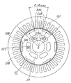
図1は本発明の第1の実施の形態における永久磁石式同期電動機の断面図である。
図において、15は永久磁石式同期電動機、27はモータシャフト、37は該モータシャフト27に固定されたロータ、38は該ロータ37の外周側に配設されたステータである。そして、前記ロータ37の外周縁の近傍には、円周方向における複数箇所に永久磁石105が埋設される。該永久磁石105は、断面が「D」字状であり、径方向における内方に平坦(たん)面166を、径方向における外方にロータ37の外周縁とほぼ平行な円弧面167を、円周方向における両側方にテーパ面168を有する。そして、前記円弧面167とテーパ面168との間に外周側屈曲部133が、前記平坦面166とテーパ面168との間に内周側屈曲部134がそれぞれ形成される。
【0023】
また、135は前記永久磁石105を支持するロータコアであり、該ロータコア135の外周縁、すなわち、前記ロータ37の外周縁の近傍には、円周方向における複数箇所に前記永久磁石105を挿入するための穴199が形成され、かつ、該各穴199間に磁極間鉄心136が、前記各永久磁石105より径方向外方に磁石保持部144がそれぞれ形成され、該磁石保持部144によって永久磁石105が包囲され保持される。
【0024】
前記ステータ38には、円周方向における複数箇所にロータ37と対向させてティース130が形成され、該ティース130は、ロータ37の外周縁部から径方向内方に向けて延びる本体部141、及び該本体部141の先端において円周方向における両側に突出し、前記ステータ38に巻装されたコイル39(図2)が抜けるのを防止するティースヘッド139から成る。そして、前記コイル39に電流を供給すると、該電流によって誘起された磁束によりステータ38とロータ37との間に反発力及び吸引力が発生させられ、前記反発力及び吸引力によってロータ37が回転するようになっている。
【0025】
ところが、前記各ティース130間にはスロット131が形成され、また、前記各永久磁石105は互いに分離させて配設されるので、ロータ37が回転すると、あるティース130を通っていた磁束が、隣接するティース130を通るようになる。
このとき、前記永久磁石105が前記スロット131を通過することによって磁束の移動が不連続になると、磁気リアクタンスの変化に伴ってステータ38とロータ37との間の吸引力が変動し、該変動によってコギングトルクが発生してしまう。
【0026】
そこで、前記永久磁石105が前記スロット131を通過するときに磁束の移動が不連続になることがなく、磁気リアクタンスの変化が生じないように、前記磁極間鉄心136の幅が設定される。すなわち、前記磁極間鉄心136によって構成される磁極間鉄心開角をθとしたとき、該磁極間鉄心開角θが前記ティース130の幅に対応させて規定される最大値θMAX と最小値θMIN との間の範囲に収まるように設定される。
【0027】
ところで、前記永久磁石105としては、各種の形状のものが提供されているので、永久磁石105のどの部分が前記スロット131を通過すると磁束の移動が不連続になるかは、永久磁石105の形状、材質等によって異なる。例えば、第1の実施の形態においては、前記外周側屈曲部133が前記スロット131を通過するときに磁束の移動が不連続になる。そこで、第1の実施の形態において、磁極間鉄心開角θは、各磁極間鉄心136の両端部における前記外周側屈曲部133と、前記モータシャフト27の中心Oとを結ぶ2本の直線が成す角度とされる。
【0028】
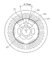
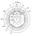
図4は本発明の第1の実施の形態における磁極間鉄心開角を最大値にしたときの永久磁石式同期電動機の断面図、図5は本発明の第1の実施の形態における磁極間鉄心開角を最小値にしたときの永久磁石式同期電動機の断面図である。
この場合、図4に示すように、磁極間鉄心136の幅に対応する3個のティース130の各ティースヘッド139の端部のうち最も離れた二つの端部をP1、P2とし、各端部P1、P2の先端とモータシャフト27の中心Oとを結ぶ2本の直線が成す角度を最大値θMAX とする。
【0029】
また、図5に示すように、磁極間鉄心136の幅に対応する3個のティース130の各端面のうち最も離れた二つの端面S1、S2の先端Q1、Q2(すなわち、前記端部P1、P2のつけね部)と、前記モータシャフト27の中心Oとを結ぶ2本の直線が成す角度を最小値θMIN とする。
したがって、磁極間鉄心開角θが
θMIN ≦θ≦θMAX
となるように設定することによって、ティース130の幅が異なっても磁気リアクタンスが変化することがなくなるので、コギングトルクが発生するのを十分に抑制することができる。また、トルクリップルが発生するのを十分に抑制することもできる。なお、本実施の形態において、前記磁極間鉄心136の幅に対応するティース130は3個あるが、磁極間鉄心136の幅が変化すると、対応するティース130の個数も変化する。
【0030】
図6は実験結果による磁極間鉄心開角とトルク変動率との関係を表す図、図7は実験結果によるロータ回転角とトルク/トルク平均値との関係を表す図である。なお、図6において、横軸に磁極間鉄心開角θを、縦軸にトルク変動率を、図7において、横軸にロータ回転角を、縦軸にトルク/トルク平均値を採ってある。
【0031】
図6においては、スロット131のピッチ、すなわち、スロットピッチを10〔°〕とし、ティース130の最も離れた二つの端面S1(図5)、S2の先端Q1、Q2とモータシャフト27の中心Oとを結ぶ2本の直線が成す角度を25〔°〕とし、ティースヘッド139の端部のうち最も離れた二つの端部P1(図4)、P2とモータシャフト27の中心Oとを結ぶ2本の直線が成す角度を27.5〔°〕としたときの、磁極間鉄心開角θに対するトルク変動率が示される。図から分かるように、磁極間鉄心開角θが
25≦θ≦27.5 〔°〕
となるときに、トルク変動率が小さくなり、コギングトルクが発生するのが十分に抑制される。この場合、
θMIN =25 〔°〕
θMAX =27.5 〔°〕
になり、最小値θMIN はティース130の最も離れた二つの端面S1、S2の先端Q1、Q2とモータシャフト27の中心Oとを結ぶ2本の直線が成す角度を、最大値θMAX はティースヘッド139の端部のうち最も離れた二つの端部P1、P2とモータシャフト27の中心Oとを結ぶ2本の直線が成す角度をそれぞれ表す。
【0032】
したがって、磁極間鉄心開角θを
θMIN ≦θ≦θMAX
と設定すればよいことが分かる。
また、図7において、aは磁極間鉄心開角θを27.5〔°〕にしたときの、bは磁極間鉄心開角θを26〔°〕にしたときの、cは磁極間鉄心開角θを25〔°〕にしたときのロータ回転角とトルク/トルク平均値との関係を示す。
【0033】
次に、前記永久磁石式同期電動機15(図1)におけるロータ37の製造方法について説明する。
▲1▼Nd、Fe、B、Co等の原料を溶解させて磁石合金インゴットにする。そして、該磁石合金インゴットを粉砕して粉末にし、永久磁石105の「D」字状の原型を磁場中で成形する。また、前記「D」字状の原型を焼結し、時効処理(アニーリング)を施す。
▲2▼ロータコア135の穴199と接触する永久磁石105のテーパ面168を研削加工し、永久磁石105の製造を完成する。このとき、前記穴199と接触しない前記円弧面167を同時に研削加工することもできる。
▲3▼Niラックメッキ又はNiバレルメッキによって前記永久磁石105に表面処理を施す。
▲4▼穴199、磁極間鉄心136、磁石保持部144等を備えた電磁鋼板をプレス加工によって打ち抜く。
▲5▼前記電磁鋼板を積層してモータシャフト27に嵌合し、ロータコア135を形成する。
▲6▼前記永久磁石105を、前記モータシャフト27の軸方向から各磁極間鉄心136間の前記穴199に挿入する。
▲7▼ロータコア135の両端において、ストッパ106(図2)、107をそれぞれモータシャフト27に嵌合し、ロータ37を形成する。これによって、前記永久磁石105の軸方向位置は前記ストッパ106、107によって決まる。
▲8▼着磁ヨーク内において前記ロータ37にパルス電流による磁場を与えることによって、前記永久磁石105のすべての磁極について同時に着磁させ、ロータ37が完成する。
【0034】
次に、本発明の第2の実施の形態について説明する。
図8は本発明の第2の実施の形態における磁極間鉄心開角を最大値にしたときの永久磁石式同期電動機の断面図、図9は本発明の第2の実施の形態における磁極間鉄心開角を最小値にしたときの永久磁石式同期電動機の断面図である。
この場合、永久磁石205は、断面が「D」字状であり、径方向における内方に平坦面206を、径方向における外方にロータ37の外周縁とほぼ平行な円弧面207を、円周方向における両側方に垂直面208を有する。そして、前記円弧面207と垂直面208との間に外周側屈曲部233が形成される。
【0035】
そこで、第2の実施の形態において、磁極間鉄心開角θは、各磁極間鉄心236の両端部における前記外周側屈曲部233と、モータシャフト27の中心Oとを結ぶ2本の直線が成す角度とされる。
そして、図8に示すように、磁極間鉄心236の幅に対応する3個のティース130の各ティースヘッド139の端部のうち最も離れた二つの端部をP1、P2とし、各端部P1、P2の先端と前記中心Oとを結ぶ2本の直線が成す角度を最大値θMAX とする。
【0036】
また、図9に示すように、磁極間鉄心236の幅に対応する3個のティース130の各端面のうち最も離れた二つの端面S1、S2の先端Q1、Q2と、前記中心Oとを結ぶ2本の直線が成す角度を最小値θMIN とする。
したがって、前記第1の実施の形態と同様に、磁極間鉄心開角θが
θMIN ≦θ≦θMAX
となるように設定することによって、トルク変動率を小さくすることができ、コギングトルクが発生するのを十分に抑制することができる。
【0037】
次に、本発明の第3の実施の形態について説明する。
図10は本発明の第3の実施の形態における磁極間鉄心開角を最大値にしたときの永久磁石式同期電動機の断面図、図11は本発明の第3の実施の形態における磁極間鉄心開角を最小値にしたときの永久磁石式同期電動機の断面図である。
この場合、永久磁石305は、断面が矩(く)形状であり、径方向における内方に平坦面306を、径方向における外方に平坦面307を、円周方向における両側方に垂直面308を有する。そして、前記平坦面307と垂直面308との間に外周側屈曲部333が形成される。
【0038】
そこで、第3の実施の形態において、磁極間鉄心開角θは、各磁極間鉄心336の両端部における前記外周側屈曲部333と、モータシャフト27の中心Oとを結ぶ2本の直線が成す角度とされる。
そして、図10に示すように、磁極間鉄心336の幅に対応する3個のティース130の各ティースヘッド139の端部のうち最も離れた二つの端部をP1、P2とし、各端部P1、P2の先端と前記中心Oとを結ぶ2本の直線が成す角度を最大値θMAX とする。
【0039】
また、図11に示すように、磁極間鉄心336の幅に対応する3個のティース130の各端面のうち最も離れた二つの端面S1、S2の先端Q1、Q2と、前記中心Oとを結ぶ2本の直線が成す角度を最小値θMIN とする。
したがって、前記第1の実施の形態と同様に、磁極間鉄心開角θが
θMIN ≦θ≦θMAX
となるように設定することによって、トルク変動率を小さくすることができ、コギングトルクが発生するのを十分に抑制することができる。
【0040】
次に、本発明の第4の実施の形態について説明する。
図12は本発明の第4の実施の形態における磁極間鉄心開角を最大値にしたときの永久磁石式同期電動機の断面図、図13は本発明の第4の実施の形態における磁極間鉄心開角を最小値にしたときの永久磁石式同期電動機の断面図である。
この場合、永久磁石405は、断面が瓦(かわら)形状であり、径方向における内方にロータ37の外周縁とほぼ平行な円弧面406を、径方向における外方に前記ロータ37の外周縁とほぼ平行な円弧面407を、円周方向における両側方に垂直面408を有する。そして、各永久磁石405における前記円弧面407と垂直面408との間に外周側屈曲部433が形成される。
【0041】
そこで、第4の実施の形態において、磁極間鉄心開角θは、各磁極間鉄心436の両端部における前記外周側屈曲部433と、モータシャフト27の中心Oとを結ぶ2本の直線が成す角度とされる。
そして、図12に示すように、磁極間鉄心436の幅に対応する3個のティース130の各ティースヘッド139の端部のうち最も離れた二つの端部をP1、P2とし、各端部P1、P2の先端と前記中心Oとを結ぶ2本の直線が成す角度を最大値θMAX とする。
【0042】
また、図13に示すように、磁極間鉄心436の幅に対応する3個のティース130の各端面のうち最も離れた二つの端面S1、S2の先端Q1、Q2と、前記中心Oとを結ぶ2本の直線が成す角度を最小値θMIN とする。
したがって、前記第1の実施の形態と同様に、磁極間鉄心開角θが
θMIN ≦θ≦θMAX
となるように設定することによって、トルク変動率を小さくすることができ、コギングトルクが発生するのを十分に抑制することができる。
【0043】
次に、本発明の第5の実施の形態について説明する。
図14は本発明の第5の実施の形態における磁極間鉄心開角を最大値にしたときの永久磁石式同期電動機の断面図である。
この場合、永久磁石105は、断面が「D」字状であり、径方向における内方に平坦面166を、径方向における外方にロータ37の外周縁とほぼ平行な円弧面167を、円周方向における両側方にテーパ面168を有する。そして、前記平坦面166とテーパ面168との間に内周側屈曲部134が形成される。
【0044】
この場合、前記内周側屈曲部134がスロット131を通過するときに磁束の移動が不連続になる。そこで、第5の実施の形態において、磁極間鉄心開角θは、各磁極間鉄心136の両端部における前記内周側屈曲部134と、モータシャフト27の中心Oとを結ぶ2本の直線が成す角度とされる。
したがって、前記第1の実施の形態と同様に、磁極間鉄心開角θが
θMIN ≦θ≦θMAX
となるように設定することによって、トルク変動率を小さくすることができ、コギングトルクが発生するのを十分に抑制することができる。
【0045】
次に、本発明の第6の実施の形態について説明する。
図15は本発明の第6の実施の形態における磁極間鉄心開角を最大値にしたときの永久磁石式同期電動機の断面図である。
この場合、永久磁石205は、断面が「D」字状であり、径方向における内方に平坦面206を、径方向における外方にロータ37の外周縁とほぼ平行な円弧面207を、円周方向における両側方に垂直面208を有する。そして、前記平坦面206と垂直面208との間に内周側屈曲部234が形成される。
【0046】
そこで、第6の実施の形態において、磁極間鉄心開角θは、各磁極間鉄心236の両端部における前記内周側屈曲部234と、モータシャフト27の中心Oとを結ぶ2本の直線が成す角度とされる。
したがって、前記第1の実施の形態と同様に、磁極間鉄心開角θが
θMIN ≦θ≦θMAX
となるように設定することによって、トルク変動率を小さくすることができ、コギングトルクが発生するのを十分に抑制することができる。
【0047】
次に、本発明の第7の実施の形態について説明する。
図16は本発明の第7の実施の形態における磁極間鉄心開角を最大値にしたときの永久磁石式同期電動機の断面図である。
この場合、永久磁石305は、断面が矩形状であり、径方向における内方に平坦面306を、径方向における外方に平坦面307を、円周方向における両側方に垂直面308を有する。そして、前記平坦面306と垂直面308との間に内周側屈曲部334が形成される。
【0048】
そこで、第7の実施の形態において、磁極間鉄心開角θは、各磁極間鉄心336の両端部における前記内周側屈曲部334と、モータシャフト27の中心Oとを結ぶ2本の直線が成す角度とされる。
したがって、前記第1の実施の形態と同様に、磁極間鉄心開角θが
θMIN ≦θ≦θMAX
となるように設定することによって、トルク変動率を小さくすることができ、コギングトルクが発生するのを十分に抑制することができる。
【0049】
次に、本発明の第8の実施の形態について説明する。
図17は本発明の第8の実施の形態における磁極間鉄心開角を最大値にしたときの永久磁石式同期電動機の断面図である。
この場合、永久磁石405は、断面が瓦形状であり、径方向における内方にロータ37の外周縁とほぼ平行な円弧面406を、径方向における外方に前記ロータ37の外周縁とほぼ平行な円弧面407を、円周方向における両側方に垂直面408を有する。そして、前記円弧面406と垂直面408との間に内周側屈曲部434が形成される。
【0050】
そこで、第8の実施の形態において、磁極間鉄心開角θは、各磁極間鉄心436の両端部における前記内周側屈曲部434と、モータシャフト27の中心Oとを結ぶ2本の直線が成す角度とされる。
したがって、前記第1の実施の形態と同様に、磁極間鉄心開角θが
θMIN ≦θ≦θMAX
となるように設定することによって、トルク変動率を小さくすることができ、コギングトルクが発生するのを十分に抑制することができる。
【0051】
次に、本発明の第9の実施の形態について説明する。
図18は本発明の第9の実施の形態における磁極間鉄心開角を最大値にしたときの永久磁石式同期電動機の断面図である。
この場合、永久磁石505は、断面が「D」字状であり、径方向における内方に平坦面506を、径方向における外方に前記ロータ37の外周縁とほぼ平行な円弧面507を、円周方向における両側方に、径方向に延びるテーパ面508を有する。そして、前記円弧面507とテーパ面508との間に外周側屈曲部533が、前記平坦面506とテーパ面508との間に内周側屈曲部534がそれぞれ形成される。
【0052】
この場合、前記テーパ面508が径方向に延びるので、前記外周側屈曲部533及び内周側屈曲部534がスロット131を通過するときに磁束の移動が不連続になる。そこで、第9の実施の形態において、磁極間鉄心開角θは、各磁極間鉄心536の両端部における前記外周側屈曲部533及び内周側屈曲部534と、モータシャフト27の中心Oとを結ぶ2本の直線が成す角度とされる。
【0053】
したがって、前記第1の実施の形態と同様に、磁極間鉄心開角θが
θMIN ≦θ≦θMAX
となるように設定することによって、トルク変動率を小さくすることができ、コギングトルクが発生するのを十分に抑制することができる。
次に、本発明の第10の実施の形態について説明する。
【0054】
図19は本発明の第10の実施の形態における磁極間鉄心開角を最大値にしたときの永久磁石式同期電動機の断面図である。
この場合、永久磁石605は、断面が逆台形状であり、径方向における内方に平坦面606を、径方向における外方に平坦面607を、円周方向における両側方に、径方向に延びるテーパ面608を有する。そして、前記平坦面607とテーパ面608との間に外周側屈曲部633が、前記平坦面606とテーパ面608との間に内周側屈曲部634がそれぞれ形成される。
【0055】
そこで、第10の実施の形態において、磁極間鉄心開角θは、各磁極間鉄心636の両端部における前記外周側屈曲部633及び内周側屈曲部634と、モータシャフト27の中心Oとを結ぶ2本の直線が成す角度とされる。
したがって、前記第1の実施の形態と同様に、磁極間鉄心開角θが
θMIN ≦θ≦θMAX
となるように設定することによって、トルク変動率を小さくすることができ、コギングトルクが発生するのを十分に抑制することができる。
【0056】
次に、本発明の第11の実施の形態について説明する。
図20は本発明の第11の実施の形態における磁極間鉄心開角を最大値にしたときの永久磁石式同期電動機の断面図である。
この場合、永久磁石705は、断面が瓦形状であり、径方向における内方にロータ37の外周縁とほぼ平行な円弧面706を、径方向における外方に前記ロータ37の外周縁とほぼ平行な円弧面707を、円周方向における両側方に、径方向に延びるテーパ面708を有する。そして、前記円弧面707とテーパ面708との間に外周側屈曲部733が、前記円弧面706とテーパ面708との間に内周側屈曲部734がそれぞれ形成される。
【0057】
そこで、第11の実施の形態において、磁極間鉄心開角θは、各磁極間鉄心736の両端部における前記外周側屈曲部733及び内周側屈曲部734と、モータシャフト27の中心Oとを結ぶ2本の直線が成す角度とされる。
したがって、前記第1の実施の形態と同様に、磁極間鉄心開角θが
θMIN ≦θ≦θMAX
となるように設定することによって、トルク変動率を小さくすることができ、コギングトルクが発生するのを十分に抑制することができる。
【0058】
なお、本発明は前記実施の形態に限定されるものではなく、本発明の趣旨に基づいて種々変形させることが可能であり、それらを本発明の範囲から排除するものではない。
【0059】
【発明の効果】
以上詳細に説明したように、本発明によれば、永久磁石式同期電動機においては、円周方向における複数箇所にティースを備え、該各ティース間にスロットが形成されたステータと、該ステータの径方向内方において回転自在に支持された回転軸と、該回転軸に固定されたロータとから成る。
【0060】
そして、該ロータは、円周方向における複数箇所に埋設された永久磁石、及び該永久磁石を保持し、各永久磁石間に磁極間鉄心を形成するロータコアを備える。
また、磁極間鉄心開角をθとし、前記磁極間鉄心の幅に対応するティースの各端面のうち最も離れた二つの端面の先端と、前記回転軸の中心とを結ぶ2本の直線が成す角度の最小値をθMIN とし、前記磁極間鉄心の幅に対応するティースにおけるティースヘッドの各端部のうち最も離れた二つの端部と、前記回転軸の中心とを結ぶ2本の直線が成す角度の最大値をθMAX としたとき、
θMIN ≦θ≦θMAX
となるように前記磁極間鉄心の幅が設定される。
【0061】
この場合、永久磁石がスロットを通過するときに磁束の移動が不連続になることがなく、磁気リアクタンスの変化が生じない。したがって、コギングトルクが発生するのを十分に抑制することができる。また、トルクリップルが発生するのを十分に抑制することもできる。
【図面の簡単な説明】
【図1】本発明の第1の実施の形態における永久磁石式同期電動機の断面図である。
【図2】本発明の第1の実施の形態におけるモータ駆動装置の第1の断面図である。
【図3】本発明の第1の実施の形態におけるモータ駆動装置の第2の断面図である。
【図4】本発明の第1の実施の形態における磁極間鉄心開角を最大値にしたときの永久磁石式同期電動機の断面図である。
【図5】本発明の第1の実施の形態における磁極間鉄心開角を最小値にしたときの永久磁石式同期電動機の断面図である。
【図6】実験結果による磁極間鉄心開角とトルク変動率との関係を表す図である。
【図7】実験結果によるロータ回転角とトルク/トルク平均値との関係を表す図である。
【図8】本発明の第2の実施の形態における磁極間鉄心開角を最大値にしたときの永久磁石式同期電動機の断面図である。
【図9】本発明の第2の実施の形態における磁極間鉄心開角を最小値にしたときの永久磁石式同期電動機の断面図である。
【図10】本発明の第3の実施の形態における磁極間鉄心開角を最大値にしたときの永久磁石式同期電動機の断面図である。
【図11】本発明の第3の実施の形態における磁極間鉄心開角を最小値にしたときの永久磁石式同期電動機の断面図である。
【図12】本発明の第4の実施の形態における磁極間鉄心開角を最大値にしたときの永久磁石式同期電動機の断面図である。
【図13】本発明の第4の実施の形態における磁極間鉄心開角を最小値にしたときの永久磁石式同期電動機の断面図である。
【図14】本発明の第5の実施の形態における磁極間鉄心開角を最大値にしたときの永久磁石式同期電動機の断面図である。
【図15】本発明の第6の実施の形態における磁極間鉄心開角を最大値にしたときの永久磁石式同期電動機の断面図である。
【図16】本発明の第7の実施の形態における磁極間鉄心開角を最大値にしたときの永久磁石式同期電動機の断面図である。
【図17】本発明の第8の実施の形態における磁極間鉄心開角を最大値にしたときの永久磁石式同期電動機の断面図である。
【図18】本発明の第9の実施の形態における磁極間鉄心開角を最大値にしたときの永久磁石式同期電動機の断面図である。
【図19】本発明の第10の実施の形態における磁極間鉄心開角を最大値にしたときの永久磁石式同期電動機の断面図である。
【図20】本発明の第11の実施の形態における磁極間鉄心開角を最大値にしたときの永久磁石式同期電動機の断面図である。
【符号の説明】
15 永久磁石式同期電動機
27 モータシャフト
37 ロータ
38 ステータ
105、205、305、405、505、605、705 永久磁石
130 ティース
131 スロット
133、233、333、433、533、633、733 外周側屈曲部
134、234、334、434、534、634、734 内周側屈曲部
135 ロータコア
136、236、336、436、536、636、736 磁極間鉄心
139 ティースヘッド
166、206、306、307、506、606、607 平坦面
167、207、406、407、507、706、707 円弧面
208、308、408 垂直面
Q1、Q2 先端
P1、P2 端部
S1、S2 端面[0001]
BACKGROUND OF THE INVENTION
The present invention relates to a permanent magnet type synchronous motor.
[0002]
[Prior art]
2. Description of the Related Art Conventionally, a permanent magnet type synchronous motor includes a permanent magnet that serves as a magnetic pole of a rotor, a stator is disposed around the rotor, and a plurality of teeth are formed on the stator so as to face the rotor. . When a current is supplied to the coil wound around the stator, a repulsive force and an attractive force are generated between the stator and the rotor by a magnetic flux induced by the current, and the rotor is generated by the repulsive force and the attractive force. Is designed to rotate.
[0003]
However, slots are formed between the teeth, and the permanent magnets are separated from each other. Therefore, when the rotor rotates, the magnetic flux passing through a certain tooth passes through the adjacent teeth. become. At this time, the movement of the magnetic flux becomes discontinuous as the corner portion of the permanent magnet passes through the slot. As a result, the attractive force between the stator and the rotor varies with the change in magnetic reactance, and the cogging torque is generated due to the variation.
[0004]
Therefore, when projecting between the permanent magnets radially outward to form a projecting portion, the width of each projecting portion is A, and the slot pitch is B,
A = (n + 1/2) × B (n is an integer)
There is provided one in which the cogging torque is suppressed from occurring by setting the width A and the slot pitch B of the protrusion so as to satisfy the following equation (see Japanese Patent Laid-Open No. 1-286758). .
[0005]
And when the magnet pressing part for pressing down the permanent magnet is formed at both ends of each protruding part in the circumferential direction of the rotor, the width of the protruding part including the magnet pressing part is set as A, The width A and the slot pitch B of the protrusion are set so as to satisfy the equation.
[0006]
[Problems to be solved by the invention]
However, in the conventional permanent magnet type synchronous motor, since the cogging torque is prevented from being generated by setting the width A of the protrusion and the slot pitch B, if the width of the teeth is different, The magnetic reactance changes with the rotation of. Therefore, generation of cogging torque cannot be sufficiently suppressed.
[0007]
An object of the present invention is to solve the problems of the conventional permanent magnet type synchronous motor and to provide a permanent magnet type synchronous motor that can sufficiently suppress the occurrence of cogging torque.
[0008]
[Means for Solving the Problems]
Therefore, in the permanent magnet type synchronous motor of the present invention, teeth are provided at a plurality of locations in the circumferential direction, and slots are formed between the teeth, and are supported rotatably inward in the radial direction of the stator. And a rotor fixed to the rotating shaft.
[0009]
The rotor includes a permanent magnet embedded in a plurality of locations in the circumferential direction, and a rotor core that holds the permanent magnet and forms a magnetic core between the permanent magnets.
Further, an opening angle between the magnetic cores is θ, and two straight lines connecting the tips of the two end surfaces farthest among the respective end surfaces of the teeth corresponding to the width of the magnetic core and the center of the rotating shaft are formed. Θ is the minimum angleMINAnd an angle formed by two straight lines connecting the two most distant ends of the tooth heads of the teeth corresponding to the width of the inter-magnetic core and the center of the rotating shaft is a maximum value θ.MAXWhen
θMIN≦ θ ≦ θMAX
The width of the iron core between the magnetic poles is set so that
[0010]
DETAILED DESCRIPTION OF THE INVENTION
Hereinafter, embodiments of the present invention will be described in detail with reference to the drawings.
FIG. 2 is a first cross-sectional view of the motor drive device according to the first embodiment of the present invention, and FIG. 3 is a second cross-sectional view of the motor drive device according to the first embodiment of the present invention.
In the figure, 11 is a motor assembly, and 12 is an inverter assembly arranged immediately above the
[0011]
The
[0012]
The
[0013]
In the present embodiment, the intermediate case 16b is arranged separately on the front side of the
The
[0014]
A plurality of
A hole is formed in the center of the bottom of the cylindrical portion 14a and the center of the lid portion 14b, and a
[0015]
A
The permanent magnet type
[0016]
Therefore, the
The
[0017]
A
[0018]
A
An
[0019]
The
[0020]
Lubricating and cooling oil is accumulated in the lowermost part of the
[0021]
By the way, the
[0022]
Next, the permanent magnet type
FIG. 1 is a sectional view of a permanent magnet type synchronous motor according to a first embodiment of the present invention.
In the figure, 15 is a permanent magnet type synchronous motor, 27 is a motor shaft, 37 is a rotor fixed to the
[0023]
[0024]
The
[0025]
However, the
At this time, if the movement of the magnetic flux becomes discontinuous as the
[0026]
Therefore, the width of the
[0027]
By the way, since the thing of various shapes is provided as the said
[0028]
FIG. 4 is a cross-sectional view of the permanent magnet type synchronous motor when the opening angle between the magnetic poles in the first embodiment of the present invention is maximized, and FIG. 5 is the iron core between the magnetic poles in the first embodiment of the present invention. It is sectional drawing of a permanent-magnet-type synchronous motor when an opening angle is made into the minimum value.
In this case, as shown in FIG. 4, the two most distant ends of the tooth heads 139 of the three
[0029]
Further, as shown in FIG. 5, tips Q1 and Q2 of two end surfaces S1 and S2 farthest among the end surfaces of the three
Therefore, the iron core opening angle θ between the magnetic poles is
θMIN≦ θ ≦ θMAX
By setting so that the magnetic reactance does not change even if the width of the
[0030]
FIG. 6 is a diagram showing the relationship between the iron core opening angle between the magnetic poles and the torque fluctuation rate based on the experimental results, and FIG. 7 is a diagram showing the relationship between the rotor rotation angle and the torque / torque average value based on the experimental results. 6, the horizontal axis indicates the opening angle θ between the magnetic poles, the vertical axis indicates the torque fluctuation rate, the horizontal axis indicates the rotor rotation angle, and the vertical axis indicates the torque / torque average value.
[0031]
In FIG. 6, the pitch of the
25 ≦ θ ≦ 27.5 [°]
Then, the torque fluctuation rate is reduced, and the occurrence of cogging torque is sufficiently suppressed. in this case,
θMIN= 25 [°]
θMAX= 27.5 [°]
And the minimum value θMINIs the angle formed by two straight lines connecting the tips Q1 and Q2 of the two end surfaces S1 and S2 farthest away from the
[0032]
Therefore, the iron core opening angle θ between the magnetic poles
θMIN≦ θ ≦ θMAX
It can be seen that it can be set as follows.
Further, in FIG. 7, a is when the inter-magnetic core opening angle θ is 27.5 [°], b is when the inter-magnetic core opening angle θ is 26 [°], and c is the inter-magnetic core opening. The relationship between the rotor rotation angle and the torque / torque average value when the angle θ is 25 ° is shown.
[0033]
Next, a method for manufacturing the
(1) Raw materials such as Nd, Fe, B, and Co are dissolved to form a magnet alloy ingot. Then, the magnet alloy ingot is pulverized into powder, and the “D” -shaped prototype of the
(2) The tapered
(3) The
{Circle around (4)} An electromagnetic steel plate provided with a
(5) The electromagnetic steel plates are laminated and fitted to the
(6) The
(7) At both ends of the
(8) By applying a magnetic field by a pulse current to the
[0034]
Next, a second embodiment of the present invention will be described.
FIG. 8 is a cross-sectional view of a permanent magnet type synchronous motor when the opening angle between the magnetic poles in the second embodiment of the present invention is maximized, and FIG. 9 is an iron core between the magnetic poles in the second embodiment of the present invention. It is sectional drawing of a permanent-magnet-type synchronous motor when an opening angle is made into the minimum value.
In this case, the
[0035]
Therefore, in the second embodiment, the inter-magnetic core opening angle θ is formed by two straight lines connecting the outer peripheral side
Then, as shown in FIG. 8, the two most distant ends of the tooth heads 139 of the three
[0036]
Further, as shown in FIG. 9, the distal ends Q <b> 1 and Q <b> 2 of the two end surfaces S <b> 1 and S <b> 2 that are the farthest among the end surfaces of the three
Therefore, as in the first embodiment, the inter-magnetic core opening angle θ is
θMIN≦ θ ≦ θMAX
By setting so as to be, it is possible to reduce the torque fluctuation rate and sufficiently suppress the occurrence of cogging torque.
[0037]
Next, a third embodiment of the present invention will be described.
FIG. 10 is a sectional view of a permanent magnet type synchronous motor when the opening angle between the magnetic poles in the third embodiment of the present invention is maximized, and FIG. 11 is an iron core between the magnetic poles in the third embodiment of the present invention. It is sectional drawing of a permanent-magnet-type synchronous motor when an opening angle is made into the minimum value.
In this case, the
[0038]
Therefore, in the third embodiment, the inter-magnetic core opening angle θ is formed by two straight lines connecting the outer peripheral side
Then, as shown in FIG. 10, the two most distant ends of the tooth heads 139 of the three
[0039]
Further, as shown in FIG. 11, among the end surfaces of the three
Therefore, as in the first embodiment, the inter-magnetic core opening angle θ is
θMIN≦ θ ≦ θMAX
By setting so as to be, it is possible to reduce the torque fluctuation rate and sufficiently suppress the occurrence of cogging torque.
[0040]
Next, a fourth embodiment of the present invention will be described.
FIG. 12 is a sectional view of a permanent magnet type synchronous motor when the opening angle between the magnetic poles in the fourth embodiment of the present invention is maximized, and FIG. 13 is an iron core between the magnetic poles in the fourth embodiment of the present invention. It is sectional drawing of a permanent-magnet-type synchronous motor when an opening angle is made into the minimum value.
In this case, the
[0041]
Therefore, in the fourth embodiment, the inter-magnetic core opening angle θ is formed by two straight lines connecting the outer peripheral
Then, as shown in FIG. 12, the two most distant ends of the tooth heads 139 of the three
[0042]
Further, as shown in FIG. 13, the distal ends Q 1 and
Therefore, as in the first embodiment, the inter-magnetic core opening angle θ is
θMIN≦ θ ≦ θMAX
By setting so as to be, it is possible to reduce the torque fluctuation rate and sufficiently suppress the occurrence of cogging torque.
[0043]
Next, a fifth embodiment of the present invention will be described.
FIG. 14 is a sectional view of a permanent magnet type synchronous motor when the inter-magnetic core opening angle is maximized in the fifth embodiment of the present invention.
In this case, the
[0044]
In this case, the movement of the magnetic flux becomes discontinuous when the inner circumferential side
Therefore, as in the first embodiment, the inter-magnetic core opening angle θ is
θMIN≦ θ ≦ θMAX
By setting so as to be, it is possible to reduce the torque fluctuation rate and sufficiently suppress the occurrence of cogging torque.
[0045]
Next, a sixth embodiment of the present invention will be described.
FIG. 15 is a sectional view of a permanent magnet type synchronous motor when the inter-magnetic core opening angle is maximized in the sixth embodiment of the present invention.
In this case, the
[0046]
Therefore, in the sixth embodiment, the opening angle θ between the magnetic poles is determined by two straight lines connecting the inner peripheral side bent
Therefore, as in the first embodiment, the inter-magnetic core opening angle θ is
θMIN≦ θ ≦ θMAX
By setting so as to be, it is possible to reduce the torque fluctuation rate and sufficiently suppress the occurrence of cogging torque.
[0047]
Next, a seventh embodiment of the present invention will be described.
FIG. 16 is a cross-sectional view of a permanent magnet type synchronous motor when the inter-magnetic core opening angle is maximized in the seventh embodiment of the present invention.
In this case, the
[0048]
Therefore, in the seventh embodiment, the inter-magnetic core opening angle θ is determined by two straight lines connecting the inner peripheral side
Therefore, as in the first embodiment, the inter-magnetic core opening angle θ is
θMIN≦ θ ≦ θMAX
By setting so as to be, it is possible to reduce the torque fluctuation rate and sufficiently suppress the occurrence of cogging torque.
[0049]
Next, an eighth embodiment of the present invention will be described.
FIG. 17 is a cross-sectional view of a permanent magnet synchronous motor when the inter-magnetic core opening angle is maximized in the eighth embodiment of the present invention.
In this case, the
[0050]
Therefore, in the eighth embodiment, the opening angle θ between the magnetic poles is determined by the two straight lines connecting the inner peripheral side bent
Therefore, as in the first embodiment, the inter-magnetic core opening angle θ is
θMIN≦ θ ≦ θMAX
By setting so as to be, it is possible to reduce the torque fluctuation rate and sufficiently suppress the occurrence of cogging torque.
[0051]
Next, a ninth embodiment of the present invention will be described.
FIG. 18 is a sectional view of a permanent magnet type synchronous motor when the inter-magnetic core opening angle is maximized in the ninth embodiment of the present invention.
In this case, the
[0052]
In this case, since the tapered
[0053]
Therefore, as in the first embodiment, the inter-magnetic core opening angle θ is
θMIN≦ θ ≦ θMAX
By setting so as to be, it is possible to reduce the torque fluctuation rate and sufficiently suppress the occurrence of cogging torque.
Next, a tenth embodiment of the present invention will be described.
[0054]
FIG. 19 is a sectional view of a permanent magnet type synchronous motor when the inter-magnetic core opening angle is maximized in the tenth embodiment of the present invention.
In this case, the
[0055]
Therefore, in the tenth embodiment, the inter-magnetic core opening angle θ is determined by the outer peripheral side
Therefore, as in the first embodiment, the inter-magnetic core opening angle θ is
θMIN≦ θ ≦ θMAX
By setting so as to be, it is possible to reduce the torque fluctuation rate and sufficiently suppress the occurrence of cogging torque.
[0056]
Next, an eleventh embodiment of the present invention will be described.
FIG. 20 is a sectional view of a permanent magnet type synchronous motor when the inter-magnetic core opening angle is maximized in the eleventh embodiment of the present invention.
In this case, the
[0057]
Therefore, in the eleventh embodiment, the inter-magnetic core opening angle θ is determined by the outer peripheral side
Therefore, as in the first embodiment, the inter-magnetic core opening angle θ is
θMIN≦ θ ≦ θMAX
By setting so as to be, the torque fluctuation rate can be reduced, and the occurrence of cogging torque can be sufficiently suppressed.
[0058]
In addition, this invention is not limited to the said embodiment, It can change variously based on the meaning of this invention, and does not exclude them from the scope of the present invention.
[0059]
【The invention's effect】
As described above in detail, according to the present invention, in the permanent magnet type synchronous motor, a stator having teeth at a plurality of locations in the circumferential direction, and slots formed between the teeth, and the diameter of the stator The rotary shaft is supported rotatably inward in the direction, and the rotor is fixed to the rotary shaft.
[0060]
The rotor includes a permanent magnet embedded in a plurality of locations in the circumferential direction, and a rotor core that holds the permanent magnet and forms a magnetic core between the permanent magnets.
Further, an opening angle between the magnetic cores is θ, and two straight lines connecting the tips of the two end surfaces farthest among the respective end surfaces of the teeth corresponding to the width of the magnetic core and the center of the rotating shaft are formed. Θ is the minimum angleMINAnd the maximum value of the angle formed by the two straight lines connecting the two end portions of the teeth heads of the teeth corresponding to the width of the iron core between the magnetic poles and the center of the rotating shaft is θMAXWhen
θMIN≦ θ ≦ θMAX
The width of the iron core between the magnetic poles is set so that
[0061]
In this case, the movement of the magnetic flux does not become discontinuous when the permanent magnet passes through the slot, and the magnetic reactance does not change. Therefore, generation of cogging torque can be sufficiently suppressed. In addition, the occurrence of torque ripple can be sufficiently suppressed.
[Brief description of the drawings]
FIG. 1 is a cross-sectional view of a permanent magnet type synchronous motor according to a first embodiment of the present invention.
FIG. 2 is a first cross-sectional view of the motor drive device according to the first embodiment of the present invention.
FIG. 3 is a second cross-sectional view of the motor drive device according to the first embodiment of the present invention.
FIG. 4 is a cross-sectional view of the permanent magnet type synchronous motor when the inter-magnetic core opening angle is maximized in the first embodiment of the present invention.
FIG. 5 is a cross-sectional view of the permanent magnet type synchronous motor when the inter-magnetic core opening angle is set to a minimum value in the first embodiment of the present invention.
FIG. 6 is a diagram showing the relationship between the magnetic core opening angle between magnetic poles and the torque fluctuation rate according to the experimental results.
FIG. 7 is a diagram illustrating a relationship between a rotor rotation angle and a torque / torque average value based on experimental results.
FIG. 8 is a cross-sectional view of a permanent magnet type synchronous motor when the inter-magnetic core opening angle is maximized in the second embodiment of the present invention.
FIG. 9 is a cross-sectional view of a permanent magnet type synchronous motor when the inter-magnetic core opening angle is set to a minimum value in the second embodiment of the present invention.
FIG. 10 is a cross-sectional view of a permanent magnet type synchronous motor when a magnetic pole core opening angle is maximized in a third embodiment of the present invention.
FIG. 11 is a cross-sectional view of a permanent magnet type synchronous motor when a magnetic core opening angle between magnetic poles is set to a minimum value in a third embodiment of the present invention.
FIG. 12 is a cross-sectional view of a permanent magnet type synchronous motor when the inter-magnetic core opening angle is maximized in the fourth embodiment of the present invention.
FIG. 13 is a cross-sectional view of a permanent magnet type synchronous motor when an inter-magnetic core opening angle is set to a minimum value in a fourth embodiment of the present invention.
FIG. 14 is a cross-sectional view of a permanent magnet type synchronous motor when an inter-magnetic core opening angle is maximized in a fifth embodiment of the present invention.
FIG. 15 is a cross-sectional view of a permanent magnet type synchronous motor when a magnetic pole core opening angle is maximized in a sixth embodiment of the present invention.
FIG. 16 is a cross-sectional view of a permanent magnet type synchronous motor when an inter-magnetic core opening angle is maximized in a seventh embodiment of the present invention.
FIG. 17 is a cross-sectional view of a permanent magnet type synchronous motor when an inter-magnetic core opening angle is maximized in an eighth embodiment of the present invention.
FIG. 18 is a cross-sectional view of a permanent magnet type synchronous motor when a magnetic pole core opening angle is maximized in a ninth embodiment of the present invention.
FIG. 19 is a cross-sectional view of a permanent magnet type synchronous motor when a magnetic pole core opening angle is maximized in a tenth embodiment of the present invention.
FIG. 20 is a cross-sectional view of a permanent magnet synchronous motor when an inter-magnetic iron core opening angle is maximized in an eleventh embodiment of the present invention.
[Explanation of symbols]
15 Permanent magnet synchronous motor
27 Motor shaft
37 rotor
38 Stator
105, 205, 305, 405, 505, 605, 705 Permanent magnet
130 teeth
131 slots
133, 233, 333, 433, 533, 633, 733 Outer peripheral side bent portion
134, 234, 334, 434, 534, 634, 734 Inner peripheral side bent portion
135 rotor core
136, 236, 336, 436, 536, 636, 736 Iron core between magnetic poles
139 Teeth Head
166, 206, 306, 307, 506, 606, 607 Flat surface
167, 207, 406, 407, 507, 706, 707 Arc surface
208, 308, 408 Vertical plane
Q1, Q2 tip
P1, P2 end
S1, S2 end face
Claims (7)
θMIN ≦θ≦θMAX
となるように前記磁極間鉄心の幅が設定されることを特徴とする永久磁石式同期電動機。A stator provided with teeth at a plurality of locations in the circumferential direction, and a slot is formed between the teeth, a rotating shaft that is rotatably supported radially inward of the stator, and a rotor fixed to the rotating shaft And the rotor includes a permanent magnet embedded in a plurality of locations in the circumferential direction, and a rotor core that holds the permanent magnet and forms an inter-magnetic core between the permanent magnets, and the inter-magnetic core. The minimum value of the angle formed by two straight lines connecting the tip of the two end faces farthest among the end faces of the teeth corresponding to the width of the iron core between the magnetic poles and the center of the rotation axis is θ. θ MIN , the maximum value of the angle formed by two straight lines connecting the two most distant ends of the tooth heads of the teeth corresponding to the width of the core between the magnetic poles and the center of the rotating shaft the θ MAX When you,
θ MIN ≦ θ ≦ θ MAX
The permanent magnet type synchronous motor is characterized in that the width of the iron core between the magnetic poles is set so that
Priority Applications (1)
| Application Number | Priority Date | Filing Date | Title |
|---|---|---|---|
| JP17000297A JP3629897B2 (en) | 1997-06-26 | 1997-06-26 | Permanent magnet synchronous motor |
Applications Claiming Priority (1)
| Application Number | Priority Date | Filing Date | Title |
|---|---|---|---|
| JP17000297A JP3629897B2 (en) | 1997-06-26 | 1997-06-26 | Permanent magnet synchronous motor |
Publications (2)
| Publication Number | Publication Date |
|---|---|
| JPH1118328A JPH1118328A (en) | 1999-01-22 |
| JP3629897B2 true JP3629897B2 (en) | 2005-03-16 |
Family
ID=15896778
Family Applications (1)
| Application Number | Title | Priority Date | Filing Date |
|---|---|---|---|
| JP17000297A Expired - Fee Related JP3629897B2 (en) | 1997-06-26 | 1997-06-26 | Permanent magnet synchronous motor |
Country Status (1)
| Country | Link |
|---|---|
| JP (1) | JP3629897B2 (en) |
Families Citing this family (9)
| Publication number | Priority date | Publication date | Assignee | Title |
|---|---|---|---|---|
| JP3983004B2 (en) * | 2000-03-31 | 2007-09-26 | 山洋電気株式会社 | Synchronous motor with built-in permanent magnet |
| JP3816727B2 (en) * | 2000-05-24 | 2006-08-30 | 株式会社東芝 | Permanent magnet type reluctance type rotating electrical machine |
| JP3708855B2 (en) * | 2000-09-13 | 2005-10-19 | 山洋電気株式会社 | Synchronous motor with built-in permanent magnet |
| TW538578B (en) | 2000-09-13 | 2003-06-21 | Sanyo Electric Co | Synchronous motor with built-in type permanent magnet |
| DE10316831A1 (en) | 2002-04-15 | 2003-11-27 | Denso Corp | Permanent magnet rotor for rotary electric machine with inner rotor has all permanent magnets magnetized in such a way that direction of magnetization is same looking in radial direction |
| JP5482423B2 (en) * | 2010-05-11 | 2014-05-07 | 株式会社デンソー | Electric motor |
| JP5687072B2 (en) * | 2011-01-04 | 2015-03-18 | アスモ株式会社 | motor |
| US8916999B2 (en) | 2011-01-01 | 2014-12-23 | Asmo Co., Ltd. | Motors containing segment conductor coils |
| CN106849579B (en) * | 2017-01-17 | 2019-07-12 | 广东美芝制冷设备有限公司 | Magneto and compressor with it |
-
1997
- 1997-06-26 JP JP17000297A patent/JP3629897B2/en not_active Expired - Fee Related
Also Published As
| Publication number | Publication date |
|---|---|
| JPH1118328A (en) | 1999-01-22 |
Similar Documents
| Publication | Publication Date | Title |
|---|---|---|
| JP3500822B2 (en) | Permanent magnet synchronous motor | |
| JP5858232B2 (en) | Rotor core, motor, and motor manufacturing method | |
| CN101779366B (en) | Axial gap type motor | |
| EP2110933B1 (en) | Motor, rotor structure and magnetic machine | |
| CN103872868B (en) | Multiple level formula electric rotating machine | |
| US5990591A (en) | Permanent magnet type synchronous motor | |
| CN202940656U (en) | Motor | |
| JP4586717B2 (en) | motor | |
| EP1964242B1 (en) | Rotor assembly for use in line start permanent magnet synchronous motor | |
| CN102487224A (en) | Magnet embedded rotor, electric motor, and assembly method of electric motor | |
| US20070247015A1 (en) | Rotor having lobed bore and method of assembling same | |
| JP3629897B2 (en) | Permanent magnet synchronous motor | |
| JP7400521B2 (en) | Motor manufacturing method | |
| US9172293B2 (en) | Hybrid stepping motor | |
| CN103795166A (en) | Rotor and rotating electric machine having the same | |
| JP3928297B2 (en) | Electric motor and manufacturing method thereof | |
| CN107040061A (en) | The built-in motor of magnet | |
| JP2014155357A (en) | Brushless motor | |
| CN102106058A (en) | Permanent magnet synchronous motor | |
| JP5193094B2 (en) | Permanent magnet motor | |
| WO2019198464A1 (en) | Motor and brushless wiper motor | |
| EP3780347A1 (en) | Motor and brushless wiper motor | |
| JP4694253B2 (en) | Permanent magnet rotating electric machine | |
| CN102882296A (en) | Rotating electrical machine | |
| JP2019022430A (en) | Motor and brushless wiper motor |
Legal Events
| Date | Code | Title | Description |
|---|---|---|---|
| A977 | Report on retrieval |
Free format text: JAPANESE INTERMEDIATE CODE: A971007 Effective date: 20040226 |
|
| A131 | Notification of reasons for refusal |
Free format text: JAPANESE INTERMEDIATE CODE: A131 Effective date: 20040309 |
|
| TRDD | Decision of grant or rejection written | ||
| A01 | Written decision to grant a patent or to grant a registration (utility model) |
Free format text: JAPANESE INTERMEDIATE CODE: A01 Effective date: 20041124 |
|
| A61 | First payment of annual fees (during grant procedure) |
Free format text: JAPANESE INTERMEDIATE CODE: A61 Effective date: 20041207 |
|
| R150 | Certificate of patent or registration of utility model |
Free format text: JAPANESE INTERMEDIATE CODE: R150 |
|
| FPAY | Renewal fee payment (event date is renewal date of database) |
Free format text: PAYMENT UNTIL: 20081224 Year of fee payment: 4 |
|
| FPAY | Renewal fee payment (event date is renewal date of database) |
Free format text: PAYMENT UNTIL: 20091224 Year of fee payment: 5 |
|
| FPAY | Renewal fee payment (event date is renewal date of database) |
Free format text: PAYMENT UNTIL: 20091224 Year of fee payment: 5 |
|
| FPAY | Renewal fee payment (event date is renewal date of database) |
Free format text: PAYMENT UNTIL: 20101224 Year of fee payment: 6 |
|
| FPAY | Renewal fee payment (event date is renewal date of database) |
Free format text: PAYMENT UNTIL: 20111224 Year of fee payment: 7 |
|
| FPAY | Renewal fee payment (event date is renewal date of database) |
Free format text: PAYMENT UNTIL: 20111224 Year of fee payment: 7 |
|
| FPAY | Renewal fee payment (event date is renewal date of database) |
Free format text: PAYMENT UNTIL: 20121224 Year of fee payment: 8 |
|
| FPAY | Renewal fee payment (event date is renewal date of database) |
Free format text: PAYMENT UNTIL: 20131224 Year of fee payment: 9 |
|
| LAPS | Cancellation because of no payment of annual fees |