WO2019198464A1 - Motor and brushless wiper motor - Google Patents
Motor and brushless wiper motor Download PDFInfo
- Publication number
- WO2019198464A1 WO2019198464A1 PCT/JP2019/012074 JP2019012074W WO2019198464A1 WO 2019198464 A1 WO2019198464 A1 WO 2019198464A1 JP 2019012074 W JP2019012074 W JP 2019012074W WO 2019198464 A1 WO2019198464 A1 WO 2019198464A1
- Authority
- WO
- WIPO (PCT)
- Prior art keywords
- permanent magnet
- salient pole
- motor
- rotor
- circumferential
- Prior art date
Links
Images

Classifications
-
- H—ELECTRICITY
- H02—GENERATION; CONVERSION OR DISTRIBUTION OF ELECTRIC POWER
- H02K—DYNAMO-ELECTRIC MACHINES
- H02K1/00—Details of the magnetic circuit
- H02K1/06—Details of the magnetic circuit characterised by the shape, form or construction
- H02K1/22—Rotating parts of the magnetic circuit
- H02K1/27—Rotor cores with permanent magnets
- H02K1/2706—Inner rotors
- H02K1/272—Inner rotors the magnetisation axis of the magnets being perpendicular to the rotor axis
- H02K1/274—Inner rotors the magnetisation axis of the magnets being perpendicular to the rotor axis the rotor consisting of two or more circumferentially positioned magnets
- H02K1/2753—Inner rotors the magnetisation axis of the magnets being perpendicular to the rotor axis the rotor consisting of two or more circumferentially positioned magnets the rotor consisting of magnets or groups of magnets arranged with alternating polarity
- H02K1/278—Surface mounted magnets; Inset magnets
-
- B—PERFORMING OPERATIONS; TRANSPORTING
- B60—VEHICLES IN GENERAL
- B60S—SERVICING, CLEANING, REPAIRING, SUPPORTING, LIFTING, OR MANOEUVRING OF VEHICLES, NOT OTHERWISE PROVIDED FOR
- B60S1/00—Cleaning of vehicles
- B60S1/02—Cleaning windscreens, windows or optical devices
- B60S1/04—Wipers or the like, e.g. scrapers
- B60S1/06—Wipers or the like, e.g. scrapers characterised by the drive
- B60S1/08—Wipers or the like, e.g. scrapers characterised by the drive electrically driven
-
- H—ELECTRICITY
- H02—GENERATION; CONVERSION OR DISTRIBUTION OF ELECTRIC POWER
- H02K—DYNAMO-ELECTRIC MACHINES
- H02K21/00—Synchronous motors having permanent magnets; Synchronous generators having permanent magnets
- H02K21/12—Synchronous motors having permanent magnets; Synchronous generators having permanent magnets with stationary armatures and rotating magnets
- H02K21/14—Synchronous motors having permanent magnets; Synchronous generators having permanent magnets with stationary armatures and rotating magnets with magnets rotating within the armatures
- H02K21/16—Synchronous motors having permanent magnets; Synchronous generators having permanent magnets with stationary armatures and rotating magnets with magnets rotating within the armatures having annular armature cores with salient poles
-
- H—ELECTRICITY
- H02—GENERATION; CONVERSION OR DISTRIBUTION OF ELECTRIC POWER
- H02K—DYNAMO-ELECTRIC MACHINES
- H02K7/00—Arrangements for handling mechanical energy structurally associated with dynamo-electric machines, e.g. structural association with mechanical driving motors or auxiliary dynamo-electric machines
- H02K7/10—Structural association with clutches, brakes, gears, pulleys or mechanical starters
- H02K7/116—Structural association with clutches, brakes, gears, pulleys or mechanical starters with gears
- H02K7/1163—Structural association with clutches, brakes, gears, pulleys or mechanical starters with gears where at least two gears have non-parallel axes without having orbital motion
- H02K7/1166—Structural association with clutches, brakes, gears, pulleys or mechanical starters with gears where at least two gears have non-parallel axes without having orbital motion comprising worm and worm-wheel
-
- H—ELECTRICITY
- H02—GENERATION; CONVERSION OR DISTRIBUTION OF ELECTRIC POWER
- H02K—DYNAMO-ELECTRIC MACHINES
- H02K2213/00—Specific aspects, not otherwise provided for and not covered by codes H02K2201/00 - H02K2211/00
- H02K2213/03—Machines characterised by numerical values, ranges, mathematical expressions or similar information
-
- H—ELECTRICITY
- H02—GENERATION; CONVERSION OR DISTRIBUTION OF ELECTRIC POWER
- H02K—DYNAMO-ELECTRIC MACHINES
- H02K29/00—Motors or generators having non-mechanical commutating devices, e.g. discharge tubes or semiconductor devices
- H02K29/03—Motors or generators having non-mechanical commutating devices, e.g. discharge tubes or semiconductor devices with a magnetic circuit specially adapted for avoiding torque ripples or self-starting problems
-
- H—ELECTRICITY
- H02—GENERATION; CONVERSION OR DISTRIBUTION OF ELECTRIC POWER
- H02K—DYNAMO-ELECTRIC MACHINES
- H02K5/00—Casings; Enclosures; Supports
- H02K5/04—Casings or enclosures characterised by the shape, form or construction thereof
- H02K5/16—Means for supporting bearings, e.g. insulating supports or means for fitting bearings in the bearing-shields
- H02K5/163—Means for supporting bearings, e.g. insulating supports or means for fitting bearings in the bearing-shields radially supporting the rotary shaft at only one end of the rotor
Definitions
- the present invention relates to a motor and a brushless wiper motor.
- a brushless motor (hereinafter sometimes simply referred to as a motor) includes a stator having teeth around which a coil is wound, and a rotor that is rotatably provided on the radial inner side of the stator. Slots are formed between adjacent teeth in the circumferential direction. A coil is wound around each tooth through this slot. An interlinkage magnetic flux is formed in the stator by supplying power to the coil.
- the rotor includes a shaft, a substantially columnar rotor core that is fitted and fixed to the shaft, and a permanent magnet provided on the rotor core. For example, a ferrite magnet is used as the permanent magnet. Then, a magnetic attractive force or a repulsive force is generated between the interlinkage magnetic flux formed in the stator and the permanent magnet provided in the rotor core, and the rotor continuously rotates.
- a rotor having a salient pole protruding outward in the radial direction between permanent magnets adjacent in the circumferential direction on the outer peripheral surface of the rotor core has been proposed (for example, see Patent Document 1).
- a direction in which the interlinkage magnetic flux (q-axis magnetic flux) due to the stator coil easily flows and a direction in which the interlinkage magnetic flux hardly flows (d-axis direction) are formed.
- reluctance torque is generated in the rotor core, and this reluctance torque can also contribute to the rotational force of the rotor.
- the ratio of the number of magnetic poles to the number of teeth (number of slots) is 2: 3.
- the present invention provides a motor and a brushless that can prevent the rotor core from stopping at the rotation angle at which the permanent magnet is most likely to demagnetize when the ratio of the number of magnetic poles of the permanent magnet to the number of teeth is 2: 3.
- a wiper motor is provided.
- a motor according to the present invention is wound around a tooth having an annular stator core, a stator having a plurality of teeth projecting radially inward from an inner peripheral surface of the stator core, and A coil rotating on the radially inner side of the stator core, a rotor core fixed to the shaft and having a rotational axis of the shaft as a radial center, and an outer peripheral surface of the rotor core, wherein the orientation of magnetization is A plurality of permanent magnets in parallel orientation and the permanent magnets adjacent in the circumferential direction of the outer peripheral surface of the rotor core are formed to protrude outward in the radial direction, and the circumferential side surfaces of the permanent magnet are in contact with each other.
- the ratio of the number of magnetic poles of the permanent magnet to the number of teeth is 2: 3, and the permanent magnet is provided on the circumferential side surface of the permanent magnet.
- An inclined surface formed so as to be gradually separated from the salient pole is formed toward the outer peripheral surface of the outer side in the radial direction, and the rotation axis is connected to a corner where the inclined surface and the outer peripheral surface are connected.
- the angle between the straight line and the straight line connecting the outermost radial direction on the circumferential side surface of the salient pole and the rotation axis is an electrical angle of 13 ° or more.
- the permanent magnet is a ferrite magnet.
- the inclined surface of the permanent magnet is parallel to a straight line connecting a circumferential center of the permanent magnet and the rotation axis.
- Such a configuration can facilitate the production of the permanent magnet and reduce the cost of the permanent magnet. Moreover, since the circumferential direction both side surfaces of a permanent magnet become parallel, the circumferential direction both side surfaces of a salient pole also become parallel. For this reason, the saturation of the magnetic flux which flows through a salient pole can be suppressed compared with the case where a salient pole is trapezoid seeing from a rotation axis direction, for example.
- the motor according to the present invention is characterized in that a circumferential width dimension at the radially outer end of the salient pole is 40 ° or less in electrical angle.
- the inductance value in the q-axis direction can be reduced, and the demagnetizing field can be suppressed. Can do.
- a circumferential width dimension at the radially outer end of the salient pole is 20 ° or more in electrical angle.
- the magnetic field concentrates on the salient pole so that the demagnetizing field hardly acts on the end of the permanent magnet.
- the effect of becoming can be obtained with certainty.
- a high reluctance torque can be obtained by setting the electrical angle of the salient pole to 20 ° or more and 40 ° or less.
- one groove portion is formed on the radially outer end face of the salient pole along the rotational axis direction, and the groove width gradually increases in the circumferential direction toward the radially inner side. It is characterized by being formed so as to be narrow.
- the gap between the end face and the teeth can be non-uniform when viewed on the entire radially outer end face of the salient pole. it can.
- it is possible to suppress a rapid change in the magnetic flux density generated in the teeth before and after the salient pole passes between the teeth during the rotation of the rotor core. For this reason, the rapid torque fluctuation of the rotor core can be reduced, and the torque ripple can be reduced.
- a brushless wiper motor according to the present invention includes the motor described above.
- a brushless wiper motor can be provided.
- the order of the cogging torque is increased more than usual even in a motor having salient poles. Can be prevented. For this reason, it is possible to prevent the rotor core from stopping at the rotation angle at which the permanent magnet is most likely to demagnetize.
- FIG. 2 is a cross-sectional view taken along line AA in FIG.
- FIG. 6 is a block diagram of the stator and rotor in embodiment of this invention.
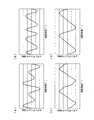
- FIG. 6 is a graph showing a change in cogging torque in the embodiment of the present invention, wherein (a) to (d) change the electrical angle of the inclined surface formed in the permanent magnet.
- It is a graph which shows the q axis
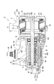
- FIG. 1 is a perspective view of the wiper motor 1.
- FIG. 2 is a cross-sectional view taken along line AA in FIG.
- the wiper motor 1 serves as a drive source for a wiper mounted on a vehicle, for example.
- the wiper motor 1 includes a motor unit 2, a deceleration unit 3 that decelerates and outputs the rotation of the motor unit 2, and a controller unit 4 that performs drive control of the motor unit 2.
- the axial direction simply refers to the rotational axis direction of the shaft 31 of the motor unit 2
- the simple circumferential direction refers to the circumferential direction of the shaft 31
- the simple radial direction refers to the shaft.
- the radial direction of 31 shall be said.
- the motor unit 2 includes a motor case 5, a substantially cylindrical stator 8 housed in the motor case 5, and a rotor 9 provided on the radially inner side of the stator 8 and rotatable with respect to the stator 8. And.
- the motor unit 2 is a so-called brushless motor that does not require a brush when supplying power to the stator 8.
- the motor case 5 is formed of a material having excellent heat dissipation, such as aluminum die casting.
- the motor case 5 includes a first motor case 6 and a second motor case 7 that are configured to be separable in the axial direction.
- the first motor case 6 and the second motor case 7 are each formed in a bottomed cylindrical shape.
- the first motor case 6 is integrally formed with the gear case 40 so that the bottom 10 is joined to the gear case 40 of the speed reduction unit 3.
- a through-hole 10a through which the shaft 31 of the rotor 9 can be inserted is formed at a substantially central portion of the bottom portion 10 in the radial direction.
- an outer flange portion 16 that projects outward in the radial direction is formed in the opening 6 a of the first motor case 6, and is stretched outward in the radial direction in the opening 7 a of the second motor case 7.
- An outer flange portion 17 is formed.
- a motor case 5 having an internal space is formed by abutting these outer flange portions 16 and 17 together.
- a stator 8 is disposed in the internal space of the motor case 5 so as to be fitted into the first motor case 6 and the second motor case 7.
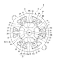
- FIG. 3 shows the configuration of the stator 8 and the rotor 9 and corresponds to a view seen from the axial direction.
- the stator 8 includes a cylindrical core portion 21 whose cross-sectional shape along the radial direction is substantially circular, and a plurality of (for example, a main body) projecting radially inward from the core portion 21.
- teeth 22 and a stator core 20 are integrally formed.
- the stator core 20 is formed by laminating a plurality of metal plates in the axial direction.
- the stator core 20 is not limited to the case where a plurality of metal plates are laminated in the axial direction, and may be formed, for example, by press-molding soft magnetic powder.
- the teeth 22 are formed by integrally forming a teeth main body 101 projecting along the radial direction from the inner peripheral surface of the core portion 21 and a flange 102 extending along the circumferential direction from the radial inner end of the teeth main body 101. It is.
- the flange portion 102 is formed so as to extend from the teeth body 101 to both sides in the circumferential direction.
- the slot 19 is formed between the collar parts 102 adjacent in the circumferential direction.
- each of the teeth 22 is covered with a resin insulator 23.
- a coil 24 is wound around each of the teeth 22 from above the insulator 23.
- Each coil 24 generates a magnetic field for rotating the rotor 9 by power feeding from the controller unit 4.
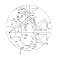
- FIG. 4 is an enlarged view of a portion A in FIG.
- the rotor 9 is rotatably provided on the radially inner side of the stator 8 through a minute gap.
- the rotor 9 has a substantially cylindrical shape with a shaft 31 integrally formed with a worm shaft 44 (see FIG. 2) constituting the speed reduction portion 3 and an outer fitting and fixing to the shaft 31 and having the shaft 31 as an axis (rotation axis) C1.
- the rotor core 32 and four permanent magnets 33 provided on the outer peripheral surface 32b of the rotor core 32 are provided.
- the permanent magnet 33 it is preferable to use a ferrite magnet.
- the ratio between the number of magnetic poles of the permanent magnet 33 and the number of slots 19 (teeth 22) is 2: 3.
- the rotor core 32 is formed by laminating a plurality of metal plates in the axial direction.
- the rotor core 32 is not limited to the case where a plurality of metal plates are laminated in the axial direction, and may be formed, for example, by press-molding soft magnetic powder.
- a through hole 32 a penetrating in the axial direction is formed at a substantially central portion in the radial direction of the rotor core 32.
- the shaft 31 is press-fitted into the through hole 32a.
- the shaft 31 may be inserted into the through hole 32a, and the rotor core 32 may be externally fixed to the shaft 31 using an adhesive or the like.
- salient poles 35 are provided on the outer peripheral surface 32b of the rotor core 32 at equal intervals in the circumferential direction.
- the salient poles 35 are formed so as to protrude outward in the radial direction and extend in the entire axial direction of the rotor core 32.
- Round chamfered portions 35 a are formed at the corners on the radially outer side of the salient poles 35 and on both sides in the circumferential direction.
- the salient pole 35 has a circumferential width dimension at the radially outer end 35t of 20 ° or more and 40 ° or less in electrical angle ⁇ .
- the circumferential width dimension at the radially outer end 35t of the salient pole 35 refers to both circumferential corners 35b (hereinafter referred to as salient poles) when the salient pole 35 is not formed with a round chamfer 35a. (Referred to as a radial corner 35b).
- the circumferential width dimension at the radially outer end 35t of the salient pole 35 will be simply referred to as the circumferential width dimension of the salient pole 35.
- the salient pole 35 is formed so that both side surfaces 35c opposed in the circumferential direction are parallel to each other. That is, the salient pole 35 is formed so that the circumferential width dimension is uniform in the radial direction. Furthermore, one groove portion 91 is formed in the axially outer end portion 35t of the salient pole 35 at substantially the center in the circumferential direction over the entire axial direction. The groove portion 91 is formed in a substantially V-groove shape so that the groove width in the circumferential direction gradually narrows toward the inner side in the radial direction.
- the outer peripheral surface 32b of the rotor core 32 formed in this way is configured as a magnet storage portion 36 between two salient poles 35 adjacent in the circumferential direction.
- Permanent magnets 33 are disposed in these magnet storage portions 36 and are fixed to the rotor core 32 by, for example, an adhesive.
- the arc center Co of the outer circumferential surface 33a on the radially outer side and the arc center Ci of the inner circumferential surface 33b on the radially inner side coincide with the position of the axis C1 of the shaft 31.
- the diameter of the circle passing through the end portion 35 t of the salient pole 35 is the same as the diameter of the outer peripheral surface 33 a of the permanent magnet 33.
- the entire inner peripheral surface 33 b of the permanent magnet 33 is in contact with the outer peripheral surface 32 b of the rotor core 32. Further, both side surfaces in the circumferential direction of the permanent magnet 33 are located on the radially inner side, a salient pole contact surface 33d that is in contact with the side surface 35c of the salient pole 35, and a radially outer side than the salient pole contact surface 33d.
- the inclined surface 33e located is smoothly connected.
- the salient pole contact surface 33d is smoothly connected to the inner peripheral surface 33b via the arc surface 33g.
- the inclined surface 33e is formed so as to be inclined and flat so as to gradually move away from the salient pole 35 as it goes from the radially outer end of the salient pole contact surface 33d toward the outer peripheral surface 33a of the permanent magnet 33.
- the inclined surfaces 33 e on both sides in the circumferential direction are parallel to a straight line L ⁇ b> 1 connecting the circumferential intermediate portion 33 c of the permanent magnet 33 and the axis C ⁇ b> 1 of the shaft 31. For this reason, the two inclined surfaces 33e are also parallel to each other.
- the shaft 31 has an outer peripheral corner 33f to which the straight line L2 connecting the radial corner 35b of the salient pole 35 and the axis C1 of the shaft 31, the inclined surface 33e of the permanent magnet 33 and the outer peripheral surface 33a are connected.
- the angle ⁇ 2 between the straight line L3 connecting the axis C1 and the electrical angle is 13 ° or more. In the following description, the angle ⁇ 2 will be described as the electrical angle ⁇ 2 of the inclined surface 33e.
- the permanent magnet 33 is magnetized so that the magnetization (magnetic field) is oriented in parallel along the thickness direction. And the permanent magnet 33 is arrange
- the speed reduction unit 3 includes a gear case 40 to which the motor case 5 is attached, and a worm speed reduction mechanism 41 accommodated in the gear case 40.
- the gear case 40 is made of a material with excellent heat dissipation, such as aluminum die cast.
- the gear case 40 is formed in a box shape having an opening 40a on one surface, and has a gear housing portion 42 for housing the worm reduction mechanism 41 therein.
- the side wall 40b of the gear case 40 is formed with an opening 43 that communicates the through hole 10a of the first motor case 6 and the gear housing portion 42 at a location where the first motor case 6 is integrally formed. Yes.
- a substantially cylindrical bearing boss 49 projects from the bottom wall 40c of the gear case 40.
- the bearing boss 49 is for rotatably supporting the output shaft 48 of the worm reduction mechanism 41, and a sliding bearing (not shown) is provided on the inner peripheral surface. Further, an O-ring (not shown) is mounted on the inner peripheral edge of the bearing boss 49. This prevents dust and water from entering from the outside to the inside via the bearing boss 49.
- a plurality of ribs 52 are provided on the outer peripheral surface of the bearing boss 49. Thereby, the rigidity of the bearing boss 49 is ensured.
- the worm speed reduction mechanism 41 accommodated in the gear accommodating portion 42 includes a worm shaft 44 and a worm wheel 45 engaged with the worm shaft 44.
- the worm shaft 44 is disposed coaxially with the shaft 31 of the motor unit 2.
- the worm shaft 44 is rotatably supported by bearings 46 and 47 provided on the gear case 40 at both ends.
- the end of the worm shaft 44 on the motor unit 2 side protrudes to the opening 43 of the gear case 40 through the bearing 46.
- the protruding end portion of the worm shaft 44 and the end portion of the shaft 31 of the motor unit 2 are joined, and the worm shaft 44 and the shaft 31 are integrated.
- the worm shaft 44 and the shaft 31 may be integrally formed by molding a worm shaft portion and a shaft portion from one base material.
- the worm wheel 45 meshed with the worm shaft 44 is provided with an output shaft 48 at the radial center of the worm wheel 45.
- the output shaft 48 is arranged coaxially with the rotational axis direction of the worm wheel 45, and protrudes to the outside of the gear case 40 via the bearing boss 49 of the gear case 40.
- a spline 48 a that can be connected to an electrical component (not shown) is formed at the protruding tip of the output shaft 48.
- a sensor magnet (not shown) is provided at the radial center of the worm wheel 45 on the side opposite to the side from which the output shaft 48 is projected.
- This sensor magnet constitutes one of the rotational position detector 60 that detects the rotational position of the worm wheel 45.
- the magnetic detection element 61 that constitutes the other of the rotational position detection unit 60 is provided in the controller unit 4 that is disposed facing the worm wheel 45 on the sensor magnet side of the worm wheel 45 (on the opening 40a side of the gear case 40). Yes.
- the controller unit 4 that controls the drive of the motor unit 2 includes a controller board 62 on which the magnetic detection element 61 is mounted, and a cover 63 provided so as to close the opening 40a of the gear case 40.
- the controller board 62 is disposed opposite to the sensor magnet side of the worm wheel 45 (opening 40a side of the gear case 40).
- the controller board 62 is obtained by forming a plurality of conductive patterns (not shown) on a so-called epoxy board.
- the controller board 62 is connected to a terminal portion of the coil 24 drawn from the stator core 20 of the motor unit 2 and electrically connected to a terminal (not shown) of the connector 11 provided on the cover 63.
- a power module (not shown) including a switching element such as a FET (Field Effect Transistor) that controls a current supplied to the coil 24 is mounted on the controller board 62.
- a capacitor (not shown) for smoothing the voltage applied to the controller board 62 is mounted on the controller board 62.
- the cover 63 covering the controller board 62 configured in this manner is formed of resin.
- the cover 63 is formed so as to bulge slightly outward.
- the inner surface side of the cover 63 is a controller housing portion 56 that houses the controller board 62 and the like.
- the connector 11 is integrally formed on the outer periphery of the cover 63. This connector 11 is formed so as to be able to be fitted with a connector 11 extending from an external power source (not shown).
- the controller board 62 is electrically connected to the terminals of the connector 11. As a result, the power of the external power supply is supplied to the controller board 62.
- a fitting portion 81 is formed on the opening edge of the cover 63 so as to be fitted with the end portion of the side wall 40 b of the gear case 40.
- the fitting portion 81 is configured by two walls 81 a and 81 b along the opening edge of the cover 63. And the edge part of the side wall 40b of the gear case 40 is inserted (fitted) between these two walls 81a and 81b.
- a labyrinth portion 83 is formed between the gear case 40 and the cover 63.
- the labyrinth 83 prevents dust and water from entering between the gear case 40 and the cover 63.
- the gear case 40 and the cover 63 are fixed by fastening a bolt (not shown).
- the wiper motor 1 Next, the operation of the wiper motor 1 will be described.
- the power supplied to the controller board 62 via the connector 11 is selectively supplied to each coil 24 of the motor unit 2 via a power module (not shown).
- a predetermined flux linkage is formed in the stator 8 (tooth 22), and a magnetic attractive force or repulsive force is generated between the flux linkage and an effective magnetic flux formed by the permanent magnet 33 of the rotor 9.
- the rotor 9 rotates continuously.
- the rotation position detection result of the worm wheel 45 detected by the magnetic detection element 61 mounted on the controller board 62 is output as a signal to an external device (not shown).
- the external device controls the switching timing of the switching elements and the like of the power module (not shown) based on the rotational position detection signal of the worm wheel 45, and the drive control of the motor unit 2 is performed.
- the output of the drive signal of the power module and the drive control of the motor unit 2 may be performed by the controller unit 4.
- the rotor 9 is a so-called SPM (Surface Permanent Magnet) type rotor in which a permanent magnet 33 is disposed on the outer peripheral surface 32 b of the rotor core 32. For this reason, the inductance value in the d-axis direction can be reduced.
- the rotor 9 is provided with salient poles 35 between the permanent magnets 33 adjacent in the circumferential direction. As a result, the inductance value in the q-axis direction due to the interlinkage magnetic flux of the stator 8 can be increased as compared with the case where the salient pole 35 is not provided. Therefore, the rotor 9 is rotated using the difference in reluctance torque between the d-axis direction and the q-axis direction.
- the reciprocity torque can contribute to the rotational torque of the rotor 9, and the interlinkage magnetic flux of the stator 8 can easily pass through both side surfaces of the permanent magnet 33 in contact with the salient poles 35. For this reason, a demagnetizing field of the permanent magnet 33 due to the interlinkage magnetic flux is generated on both circumferential sides of the permanent magnet 33. Further, by providing the salient pole 35, the magnetic flux of the permanent magnet 33 flows through the salient pole 35. For this reason, there is a possibility that the order of the cogging torque of the motor unit 2 is increased by the magnetic flux formed on the salient poles 35 than the number of magnetic poles of the rotor 9 (four poles in this embodiment).
- FIG. 5 is a graph showing changes in cogging torque when the vertical axis is the cogging torque [mNm] of the rotor 9 and the horizontal axis is the rotation angle of the rotor 9, and (a) is an inclined surface of the permanent magnet 33.
- the electrical angle ⁇ 2 of 33e is 5 °
- (b) is when the electrical angle ⁇ 2 of the inclined surface 33e of the permanent magnet 33 is 10 °
- (c) is the electrical angle of the inclined surface 33e of the permanent magnet 33.
- ⁇ 2 is 13 °
- (d) shows the case where the electrical angle ⁇ 2 of the inclined surface 33e of the permanent magnet 33 is 15 °.
- the number of peaks is the order of the cogging torque.
- the ratio between the number of magnetic poles of the permanent magnet 33 and the number of slots 19 (teeth 22) is 2: 3.
- the electrical angle ⁇ 2 of the inclined surface 33e of the permanent magnet 33 is 13
- the angle is possible to prevent the order of the cogging torque from increasing more than the number of magnetic poles of the rotor 9.
- the rotor core 32 is stopped at the rotation angle at which the permanent magnet 33 is most likely to demagnetize.
- the magnetization direction of the permanent magnet 33 is parallel orientation, cogging of the motor unit 2 can be suppressed and a high magnetic flux density can be obtained.
- the salient pole 35 of the rotor 9 is formed with a groove 91 at the end 35t.
- interval of this edge part 35t and the teeth 22 (hook part 102) of the stator 8 can be made non-uniform
- the salient poles 35 of the rotor core 32 are formed so that the circumferential width dimension is 20 ° or more and 40 ° or less in terms of the electrical angle ⁇ 1.
- the inductance value in the q-axis direction can be reduced by setting the circumferential width dimension of the salient pole 35 to 40 ° or less in terms of the electrical angle ⁇ 1.
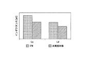
- FIG. 6 is a graph showing the inductances Lq and Ld [mH] of the q-axis and d-axis of the rotor 9, and the rotor 9 of the present embodiment is compared with the rotor of the conventional structure.
- the conventional structure here is the structure of a rotor of a so-called IPM (Interior Permanent Magnet) motor in which permanent magnets are arranged in a plurality of slits formed in the rotor core.
- IPM Interior Permanent Magnet
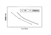
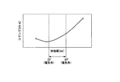
- FIG. 7 is a graph showing changes in the rotational speed of the rotor 9 when the vertical axis is the rotational speed [rpm] of the rotor 9 and the horizontal axis is the torque [N ⁇ m] of the rotor 9. More specifically, FIG. 7 is a graph showing the relationship between the torque [N ⁇ m] and the rotational speed [rpm] when the rotor 9 is subjected to advance angle energization and wide angle energization.
- the rotor 9 is compared with the conventional IPM rotor. As shown in the figure, it can be confirmed that the rotor 9 of the present embodiment generates higher torque and rotational speed than the conventional structure.
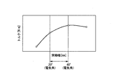
- FIG. 8 is a graph showing a change in torque of the rotor 9 when the vertical axis is the torque [N ⁇ m] of the rotor 9 and the horizontal axis is the salient pole width [mm] of the salient pole 35 provided on the rotor core 32. It is. More specifically, FIG. 8 is a graph showing the torque generated in the rotor 9 of the present embodiment when the circumferential width dimension (electrical angle ⁇ ) of the salient pole 35 is varied.
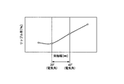
- FIG. 9 is a graph showing changes in the ripple rate of the rotor 9 when the vertical axis is the ripple rate [%] of the rotor 9 and the horizontal axis is the salient pole width [mm] of the salient pole 35 of the rotor core 32.
- FIG. 9 is a graph showing a ripple rate generated in the rotor 9 of the present embodiment when the circumferential width dimension of the salient pole 35 is varied.
- FIG. 10 is a graph showing changes in cogging of the rotor 9 when the vertical axis is the cogging [mN ⁇ m] of the rotor 9 and the horizontal axis is the salient pole width [mm] of the salient pole 35 of the rotor core 32. More specifically, FIG. 10 is a graph showing cogging generated in the rotor 9 of the present embodiment when the circumferential width of the salient pole 35 is varied.
- a high reluctance torque can be obtained. It can also be confirmed that the ripple rate and cogging torque of the motor unit 2 can be suppressed.
- the inductance value in the q-axis direction can be reduced by setting the electrical angle ⁇ 1 of the salient pole 35 to 40 ° or less and reducing the circumferential width dimension of the salient pole 35 in the circumferential direction.
- Demagnetizing field can be suppressed.
- the electrical angle ⁇ 1 of the salient pole 35 to 20 ° or more and ensuring the circumferential width dimension to be a certain level or more, the magnetic flux concentrates on the salient pole 35, so that the demagnetizing field becomes the end 33s of the permanent magnet 33. The effect that it becomes difficult to act on can be obtained reliably.
- a high reluctance torque can be obtained by setting the electrical angle ⁇ 1 of the salient pole 35 to 20 ° or more and 40 ° or less.
- the inclined surfaces 33 e on both sides in the circumferential direction are parallel to a straight line L ⁇ b> 1 connecting the circumferential intermediate portion 33 c of the permanent magnet 33 and the axis C ⁇ b> 1 of the shaft 31.
- the two inclined surfaces 33e are also parallel to each other.
- the permanent magnet 33 can be formed from a material having two parallel inclined surfaces 33e facing each other, and the manufacturing cost of the permanent magnet 33 can be reduced.
- the salient pole 35 is formed so that both side surfaces 35c facing each other in the circumferential direction are parallel to each other. That is, the salient pole 35 is formed so that the circumferential width dimension is uniform in the radial direction. For this reason, for example, the saturation of the magnetic flux flowing through the salient poles 35 can be suppressed as compared with the case where the salient poles 35 are trapezoidal when viewed from the rotation axis direction.
- the wiper motor 1 is taken as an example of the motor.
- the motor according to the present invention is not limited to the wiper motor 1, and other electrical components (for example, a power window, a sunroof, It can be used as a driving source for an electric seat or the like, and for various other purposes.
- one groove portion 91 is formed in the axially outer end portion 35t of the salient pole 35 at substantially the center in the circumferential direction.
- the present invention is not limited to this, and two or more groove portions 91 may be formed in the end portion 35 t of the salient pole 35.
- the groove part 91 demonstrated the case where it formed in the substantially V-groove shape so that the groove width of the circumferential direction may become narrow gradually as it goes to radial inside.
- the present invention is not limited to this, and it is only necessary that the groove portion 91 is formed so that the groove width in the circumferential direction gradually decreases toward the inner side in the radial direction.
- the groove portion 91 is formed in a substantially U shape. May be.
- the inclined surface 33e formed on the permanent magnet 33 is inclined so as to be gradually separated from the salient pole 35 as it goes from the radially outer end of the salient pole contact surface 33d toward the outer peripheral surface 33a of the permanent magnet 33, and The case where it is formed flat has been described.
- the inclined surface 33e only needs to be formed so as to be gradually separated from the salient poles 35 toward the outer peripheral surface 33a of the permanent magnet 33 from the radially outer end of the salient pole contact surface 33d.
- the inclined surface 33e may be formed in a curved shape.
- SYMBOLS 1 Wiper motor (motor, brushless wiper motor), 2 ... Motor part (motor), 8 ... Stator, 20 ... Stator core, 22 ... Teeth, 24 ... Coil, 31 ... Shaft, 32 ... Rotor core, 33 ... Permanent magnet, 33e ... inclined surface (slope), 33f ... outer peripheral corner (corner), 35 ... salient pole, 91 ... groove, 91a ... bottom, C1 ... axis (rotation axis), H1 ... groove depth, L1, L2, L3 ... Linear, ⁇ 1, ⁇ 2 ... Electrical angle
Abstract
Provided are a motor and a brushless wiper motor capable of preventing a rotor core from stopping at a rotation angle where permanent magnets are most easily demagnetized when the ratio of the number of magnetic poles of the permanent magnets to the number of teeth is 2:3. The motor is provided with: a rotor core 32; a plurality of permanent magnets 33 disposed on the outer circumferential surface 32b of the rotor core 32 and magnetized in parallel orientation; and a salient pole 35 saliently formed between the permanent magnets 33 adjacent in the circumferential direction of the outer circumferential surface 32b of the rotor core 32. The ratio of the number of magnetic poles of the permanent magnets 33 to the number of teeth is 2:3. Sloped surfaces 33e are formed on the side surfaces of the permanent magnets 33 in the circumferential direction. The angle θ2 between lines L3 and lines L2 is an electrical angle of 13°or more, said lines L3 connecting outer circumferential corner portions 33f where the sloped surfaces 33e and the outer circumferential surface 33a are connected to each other and the shaft center C1, said lines L2 connecting the radial direction outermost side of the circumferential direction side surface of the salient pole 35 and the shaft center C1.
Description
本発明は、モータ及びブラシレスワイパーモータに関するものである。
The present invention relates to a motor and a brushless wiper motor.
ブラシレスモータ(以下、単にモータと称することがある)は、コイルが巻回されたティースを有するステータと、ステータの径方向内側に回転自在に設けられたロータと、を備えている。周方向で隣り合うティース間には、スロットが形成される。このスロットを通して各ティースにコイルが巻回される。
ステータには、コイルに給電を行うことにより鎖交磁束が形成される。ロータは、シャフトと、このシャフトに外嵌固定される略円柱状のロータコアと、ロータコアに設けられた永久磁石と、を有している。永久磁石としては、例えば、フェライト磁石が用いられる。そして、ステータに形成された鎖交磁束とロータコアに設けられた永久磁石との間に磁気的な吸引力や反発力が生じ、ロータが継続的に回転する。 A brushless motor (hereinafter sometimes simply referred to as a motor) includes a stator having teeth around which a coil is wound, and a rotor that is rotatably provided on the radial inner side of the stator. Slots are formed between adjacent teeth in the circumferential direction. A coil is wound around each tooth through this slot.
An interlinkage magnetic flux is formed in the stator by supplying power to the coil. The rotor includes a shaft, a substantially columnar rotor core that is fitted and fixed to the shaft, and a permanent magnet provided on the rotor core. For example, a ferrite magnet is used as the permanent magnet. Then, a magnetic attractive force or a repulsive force is generated between the interlinkage magnetic flux formed in the stator and the permanent magnet provided in the rotor core, and the rotor continuously rotates.
ここで、ロータに永久磁石を配置する方式として、ロータコアの外周面に永久磁石を配置する方式(SPM:Surface Permanent Magnet)がある。このSPM方式のロータにおいて、高トルク化を図るためのさまざまな方法が提案されている。
Here, as a method of arranging the permanent magnets on the rotor, there is a method of arranging permanent magnets on the outer peripheral surface of the rotor core (SPM: Surface Permanent Magnet). Various methods for increasing the torque in the SPM rotor have been proposed.
例えば、ロータコアの外周面において、周方向で隣り合う永久磁石の間に、径方向外側に向かって突出する突極を設けたロータが提案されている(例えば、特許文献1参照)。突極を設けることにより、ロータコアにおいて、ステータのコイルによる鎖交磁束(q軸磁束)が流れやすい方向と、鎖交磁束の流れにくい方向(d軸方向)とが形成される。この結果、ロータコアにリラクタンストルクが発生するので、このリラクタンストルクもロータの回転力に寄与させることができる。ここで、特許文献1のモータは、磁極数とティースの数(スロット数)との比が2:3である。
For example, a rotor having a salient pole protruding outward in the radial direction between permanent magnets adjacent in the circumferential direction on the outer peripheral surface of the rotor core has been proposed (for example, see Patent Document 1). By providing the salient poles, in the rotor core, a direction in which the interlinkage magnetic flux (q-axis magnetic flux) due to the stator coil easily flows and a direction in which the interlinkage magnetic flux hardly flows (d-axis direction) are formed. As a result, reluctance torque is generated in the rotor core, and this reluctance torque can also contribute to the rotational force of the rotor. Here, in the motor of Patent Document 1, the ratio of the number of magnetic poles to the number of teeth (number of slots) is 2: 3.
しかしながら、磁極数とティースの数との比が2:3のようなモータにおいて、上述の従来技術のように突極を設けると、この突極に向かって鎖交磁束が流れやすくなる分、永久磁石の周方向側面(突極側の側面)に鎖交磁束による永久磁石の減磁界が発生してしまうという課題があった。
However, in a motor having a ratio of the number of magnetic poles to the number of teeth of 2: 3, if a salient pole is provided as in the above-described prior art, the interlinkage magnetic flux tends to flow toward the salient pole. There has been a problem that a demagnetizing field of the permanent magnet due to the interlinkage magnetic flux is generated on the circumferential side surface (side surface of the salient pole) of the magnet.
また、ロータコアに突極を設けると、この突極にも永久磁石による磁束が形成される。このため、通常、モータのコギングトルクの次数が「永久磁石の磁極数×ティースの数(スロット数)」の最小公倍数で決定されるところ、この最小公倍数のさらに2倍となってしまう可能性があった。この結果、最も永久磁石が減磁しやすい回転角でロータコアが停止してしまう可能性があった。最も永久磁石が減磁しやすい回転角でロータコアが停止してしまうと、再度モータを起動する際、所定よりも大きな電力を必要としてしまう。
Also, when a salient pole is provided on the rotor core, a magnetic flux by a permanent magnet is also formed on this salient pole. For this reason, the order of the cogging torque of the motor is usually determined by the least common multiple of “the number of magnetic poles of the permanent magnet × the number of teeth (the number of slots)”. there were. As a result, there is a possibility that the rotor core stops at a rotation angle at which the permanent magnet is most easily demagnetized. If the rotor core stops at a rotation angle at which the permanent magnet is most likely to be demagnetized, more power than a predetermined amount is required when the motor is started again.
そこで、本発明は、永久磁石の磁極数とティースの数との比が2:3の場合において、最も永久磁石が減磁しやすい回転角でロータコアが停止してしまうことを防止できるモータ及びブラシレスワイパーモータを提供するものである。
Therefore, the present invention provides a motor and a brushless that can prevent the rotor core from stopping at the rotation angle at which the permanent magnet is most likely to demagnetize when the ratio of the number of magnetic poles of the permanent magnet to the number of teeth is 2: 3. A wiper motor is provided.
上記の課題を解決するために、本発明に係るモータは、環状のステータコア、及び前記ステータコアの内周面から径方向内側に向かって突出する複数のティースを有するステータと、前記ティースに巻回されるコイルと、前記ステータコアの径方向内側で回転するシャフトと、前記シャフトに固定され、前記シャフトの回転軸線を径方向中心とするロータコアと、前記ロータコアの外周面に配置され、着磁の配向がパラレル配向である複数の永久磁石と、前記ロータコアの前記外周面の周方向で隣り合う前記永久磁石の間に、径方向外側に向かって突出形成され、前記永久磁石の周方向側面が当接された突極と、を備え、前記永久磁石の磁極数と前記ティースの数との比は、2:3であり、前記永久磁石の前記周方向側面には、前記永久磁石の径方向外側の外周面に向かうに従って、漸次前記突極から離間するように形成された斜面が形成されており、前記斜面と前記外周面とが接続される角部と前記回転軸線とを結ぶ直線と、前記突極の周方向側面における径方向最外側と前記回転軸線とを結ぶ直線と、の間の角度は、電気角で13°以上であることを特徴とする。
In order to solve the above problems, a motor according to the present invention is wound around a tooth having an annular stator core, a stator having a plurality of teeth projecting radially inward from an inner peripheral surface of the stator core, and A coil rotating on the radially inner side of the stator core, a rotor core fixed to the shaft and having a rotational axis of the shaft as a radial center, and an outer peripheral surface of the rotor core, wherein the orientation of magnetization is A plurality of permanent magnets in parallel orientation and the permanent magnets adjacent in the circumferential direction of the outer peripheral surface of the rotor core are formed to protrude outward in the radial direction, and the circumferential side surfaces of the permanent magnet are in contact with each other. The ratio of the number of magnetic poles of the permanent magnet to the number of teeth is 2: 3, and the permanent magnet is provided on the circumferential side surface of the permanent magnet. An inclined surface formed so as to be gradually separated from the salient pole is formed toward the outer peripheral surface of the outer side in the radial direction, and the rotation axis is connected to a corner where the inclined surface and the outer peripheral surface are connected. The angle between the straight line and the straight line connecting the outermost radial direction on the circumferential side surface of the salient pole and the rotation axis is an electrical angle of 13 ° or more.
このように構成することで、永久磁石の磁極数とティースの数との比が2:3である場合において、突極を有するモータであっても、コギングトルクの次数が通常よりも増大してしまうことを防止できる。このため、最も永久磁石が減磁しやすい回転角でロータコアが停止してしまうことを防止できる。
また、永久磁石をパラレル配向とすることにより、モータのコギングを抑えるとともに、高い磁束密度を得ることができる。 With this configuration, when the ratio of the number of magnetic poles of the permanent magnet to the number of teeth is 2: 3, the order of the cogging torque is increased more than usual even with a motor having salient poles. Can be prevented. For this reason, it is possible to prevent the rotor core from stopping at the rotation angle at which the permanent magnet is most likely to demagnetize.
Further, by setting the permanent magnets in parallel orientation, the cogging of the motor can be suppressed and a high magnetic flux density can be obtained.
本発明に係るモータにおいて、前記永久磁石は、フェライト磁石であることを特徴とする。
In the motor according to the present invention, the permanent magnet is a ferrite magnet.
このように構成することで、例えば希土類磁石と比較して、高トルクを得るために磁石の径方向寸法を大きくしても、磁石使用量増加にともなうコスト上昇を抑えることができる。
With this configuration, for example, compared with a rare earth magnet, even if the radial dimension of the magnet is increased in order to obtain a high torque, an increase in cost associated with an increase in the amount of magnet used can be suppressed.
本発明に係るモータにおいて、前記永久磁石の前記斜面は、前記永久磁石の周方向中央と前記回転軸線とを結ぶ直線と平行であることを特徴とする。
In the motor according to the present invention, the inclined surface of the permanent magnet is parallel to a straight line connecting a circumferential center of the permanent magnet and the rotation axis.
このように構成することで、永久磁石の製造を容易化でき、永久磁石のコストを低減することができる。また、永久磁石の周方向両側面が平行になるので、突極の周方向両側面も平行になる。このため、例えば、突極が回転軸線方向からみて台形の場合と比較して、突極を流れる磁束の飽和を抑えることができる。
Such a configuration can facilitate the production of the permanent magnet and reduce the cost of the permanent magnet. Moreover, since the circumferential direction both side surfaces of a permanent magnet become parallel, the circumferential direction both side surfaces of a salient pole also become parallel. For this reason, the saturation of the magnetic flux which flows through a salient pole can be suppressed compared with the case where a salient pole is trapezoid seeing from a rotation axis direction, for example.
本発明に係るモータにおいて、前記突極の前記径方向外側の端部における周方向の幅寸法は、電気角で40°以下であることを特徴とする。
The motor according to the present invention is characterized in that a circumferential width dimension at the radially outer end of the salient pole is 40 ° or less in electrical angle.
このように、突極の電気角を40°以下として、周方向における突極の周方向の幅寸法を小さくすることで、q軸方向におけるインダクタンス値を小さくすることができ、減磁界を抑えることができる。
Thus, by setting the electrical angle of the salient pole to 40 ° or less and reducing the circumferential width of the salient pole in the circumferential direction, the inductance value in the q-axis direction can be reduced, and the demagnetizing field can be suppressed. Can do.
本発明に係るモータにおいて、前記突極の前記径方向外側の端部における周方向の幅寸法は、電気角で20°以上であることを特徴とする。
In the motor according to the present invention, a circumferential width dimension at the radially outer end of the salient pole is 20 ° or more in electrical angle.
このように構成することで、突極の周方向の幅寸法を電気角で20°以上に確保することで、磁束が突極に集中することによって減磁界が永久磁石の端部に作用しにくくなるという効果を、確実に得ることができる。また、突極の電気角を20°以上40°以下とすることで、高いリラクタンストルクを得ることができる。
By configuring in this way, by ensuring that the circumferential width dimension of the salient pole is 20 ° or more in terms of electrical angle, the magnetic field concentrates on the salient pole so that the demagnetizing field hardly acts on the end of the permanent magnet. The effect of becoming can be obtained with certainty. Moreover, a high reluctance torque can be obtained by setting the electrical angle of the salient pole to 20 ° or more and 40 ° or less.
本発明に係るモータは、前記突極の前記径方向外側の端面に、前記回転軸線方向に沿って溝部を1つ形成し、前記溝部は、径方向内側に向かうに従って周方向の溝幅が徐々に狭くなるように形成されていることを特徴とする。
In the motor according to the present invention, one groove portion is formed on the radially outer end face of the salient pole along the rotational axis direction, and the groove width gradually increases in the circumferential direction toward the radially inner side. It is characterized by being formed so as to be narrow.
このように構成することで、突極の径方向外側の端面に溝部があることで、突極の径方向外側の端面全体でみたとき、この端面とティースとの間隔を不均一にすることができる。この結果、ロータコアの回転中に、突極がティース間を通過する前後でティースに生じる磁束密度の急激な変化を抑制できる。このため、ロータコアの急激なトルク変動を低減でき、トルクリップルを低下させることができる。
By having such a configuration, when there is a groove on the radially outer end face of the salient pole, the gap between the end face and the teeth can be non-uniform when viewed on the entire radially outer end face of the salient pole. it can. As a result, it is possible to suppress a rapid change in the magnetic flux density generated in the teeth before and after the salient pole passes between the teeth during the rotation of the rotor core. For this reason, the rapid torque fluctuation of the rotor core can be reduced, and the torque ripple can be reduced.
本発明に係るブラシレスワイパーモータは、上記に記載のモータを備えたことを特徴とする。
A brushless wiper motor according to the present invention includes the motor described above.
このように構成することで、永久磁石の磁極数とティースの数との比が2:3の場合において、最も永久磁石が減磁しやすい回転角でロータコアが停止してしまうことを防止可能なブラシレスワイパーモータを提供できる。
With this configuration, when the ratio of the number of magnetic poles of the permanent magnet to the number of teeth is 2: 3, it is possible to prevent the rotor core from stopping at the rotation angle at which the permanent magnet is most likely to demagnetize. A brushless wiper motor can be provided.
本発明によれば、永久磁石の磁極数とティースの数との比が2:3である場合において、突極を有するモータであっても、コギングトルクの次数が通常よりも増大してしまうことを防止できる。このため、最も永久磁石が減磁しやすい回転角でロータコアが停止してしまうことを防止できる。
According to the present invention, when the ratio of the number of magnetic poles of the permanent magnet to the number of teeth is 2: 3, the order of the cogging torque is increased more than usual even in a motor having salient poles. Can be prevented. For this reason, it is possible to prevent the rotor core from stopping at the rotation angle at which the permanent magnet is most likely to demagnetize.
次に、本発明の実施形態を図面に基づいて説明する。
Next, an embodiment of the present invention will be described based on the drawings.
(ワイパーモータ)
図1は、ワイパーモータ1の斜視図である。図2は、図1のA-A線に沿う断面図である。
図1、図2に示すように、ワイパーモータ1は、例えば車両に搭載されるワイパの駆動源となる。ワイパーモータ1は、モータ部2と、モータ部2の回転を減速して出力する減速部3と、モータ部2の駆動制御を行うコントローラ部4と、を備えている。
なお、以下の説明において、単に軸方向という場合は、モータ部2のシャフト31の回転軸線方向をいい、単に周方向という場合は、シャフト31の周方向をいい、単に径方向という場合は、シャフト31の径方向をいうものとする。 (Wiper motor)
FIG. 1 is a perspective view of thewiper motor 1. FIG. 2 is a cross-sectional view taken along line AA in FIG.
As shown in FIGS. 1 and 2, thewiper motor 1 serves as a drive source for a wiper mounted on a vehicle, for example. The wiper motor 1 includes a motor unit 2, a deceleration unit 3 that decelerates and outputs the rotation of the motor unit 2, and a controller unit 4 that performs drive control of the motor unit 2.
In the following description, the axial direction simply refers to the rotational axis direction of theshaft 31 of the motor unit 2, the simple circumferential direction refers to the circumferential direction of the shaft 31, and the simple radial direction refers to the shaft. The radial direction of 31 shall be said.
図1は、ワイパーモータ1の斜視図である。図2は、図1のA-A線に沿う断面図である。
図1、図2に示すように、ワイパーモータ1は、例えば車両に搭載されるワイパの駆動源となる。ワイパーモータ1は、モータ部2と、モータ部2の回転を減速して出力する減速部3と、モータ部2の駆動制御を行うコントローラ部4と、を備えている。
なお、以下の説明において、単に軸方向という場合は、モータ部2のシャフト31の回転軸線方向をいい、単に周方向という場合は、シャフト31の周方向をいい、単に径方向という場合は、シャフト31の径方向をいうものとする。 (Wiper motor)
FIG. 1 is a perspective view of the
As shown in FIGS. 1 and 2, the
In the following description, the axial direction simply refers to the rotational axis direction of the
(モータ部)
モータ部2は、モータケース5と、モータケース5内に収納されている略円筒状のステータ8と、ステータ8の径方向内側に設けられ、ステータ8に対して回転可能に設けられたロータ9と、を備えている。モータ部2は、ステータ8に電力を供給する際にブラシを必要としない、いわゆるブラシレスモータである。 (Motor part)
Themotor unit 2 includes a motor case 5, a substantially cylindrical stator 8 housed in the motor case 5, and a rotor 9 provided on the radially inner side of the stator 8 and rotatable with respect to the stator 8. And. The motor unit 2 is a so-called brushless motor that does not require a brush when supplying power to the stator 8.
モータ部2は、モータケース5と、モータケース5内に収納されている略円筒状のステータ8と、ステータ8の径方向内側に設けられ、ステータ8に対して回転可能に設けられたロータ9と、を備えている。モータ部2は、ステータ8に電力を供給する際にブラシを必要としない、いわゆるブラシレスモータである。 (Motor part)
The
(モータケース)
モータケース5は、例えばアルミダイキャスト等の放熱性の優れた材料に形成されている。モータケース5は、軸方向に分割可能に構成された第1モータケース6と、第2モータケース7と、からなる。第1モータケース6及び第2モータケース7は、それぞれ有底筒状に形成されている。
第1モータケース6は、底部10が減速部3のギヤケース40と接合されるように、このギヤケース40と一体成形されている。底部10の径方向略中央には、ロータ9のシャフト31を挿通可能な貫通孔10aが形成されている。 (Motor case)
The motor case 5 is formed of a material having excellent heat dissipation, such as aluminum die casting. The motor case 5 includes a first motor case 6 and a second motor case 7 that are configured to be separable in the axial direction. The first motor case 6 and the second motor case 7 are each formed in a bottomed cylindrical shape.
The first motor case 6 is integrally formed with thegear case 40 so that the bottom 10 is joined to the gear case 40 of the speed reduction unit 3. A through-hole 10a through which the shaft 31 of the rotor 9 can be inserted is formed at a substantially central portion of the bottom portion 10 in the radial direction.
モータケース5は、例えばアルミダイキャスト等の放熱性の優れた材料に形成されている。モータケース5は、軸方向に分割可能に構成された第1モータケース6と、第2モータケース7と、からなる。第1モータケース6及び第2モータケース7は、それぞれ有底筒状に形成されている。
第1モータケース6は、底部10が減速部3のギヤケース40と接合されるように、このギヤケース40と一体成形されている。底部10の径方向略中央には、ロータ9のシャフト31を挿通可能な貫通孔10aが形成されている。 (Motor case)
The motor case 5 is formed of a material having excellent heat dissipation, such as aluminum die casting. The motor case 5 includes a first motor case 6 and a second motor case 7 that are configured to be separable in the axial direction. The first motor case 6 and the second motor case 7 are each formed in a bottomed cylindrical shape.
The first motor case 6 is integrally formed with the
また、第1モータケース6の開口部6aに、径方向外側に向かって張り出す外フランジ部16が形成されていると共に、第2モータケース7の開口部7aに、径方向外側に向かって張り出す外フランジ部17が形成されている。これら外フランジ部16,17同士を突き合わせて内部空間を有するモータケース5を形成している。そして、モータケース5の内部空間に、第1モータケース6及び第2モータケース7に内嵌されるようにステータ8が配置されている。
In addition, an outer flange portion 16 that projects outward in the radial direction is formed in the opening 6 a of the first motor case 6, and is stretched outward in the radial direction in the opening 7 a of the second motor case 7. An outer flange portion 17 is formed. A motor case 5 having an internal space is formed by abutting these outer flange portions 16 and 17 together. A stator 8 is disposed in the internal space of the motor case 5 so as to be fitted into the first motor case 6 and the second motor case 7.
(ステータ)
図3は、ステータ8及びロータ9の構成を示し、軸方向からみた図に相当する。
図2、図3に示すように、ステータ8は、径方向に沿う断面形状が略円形となる筒状のコア部21と、コア部21から径方向内側に向かって突出する複数(例えば、本実施形態では6つ)のティース22と、が一体成形されたステータコア20を有している。
ステータコア20は、複数の金属板を軸方向に積層することにより形成されている。なお、ステータコア20は、複数の金属板を軸方向に積層して形成する場合に限られるものではなく、例えば、軟磁性粉を加圧成形することにより形成してもよい。 (Stator)
FIG. 3 shows the configuration of thestator 8 and the rotor 9 and corresponds to a view seen from the axial direction.
As shown in FIGS. 2 and 3, thestator 8 includes a cylindrical core portion 21 whose cross-sectional shape along the radial direction is substantially circular, and a plurality of (for example, a main body) projecting radially inward from the core portion 21. In the embodiment, 6) teeth 22 and a stator core 20 are integrally formed.
Thestator core 20 is formed by laminating a plurality of metal plates in the axial direction. The stator core 20 is not limited to the case where a plurality of metal plates are laminated in the axial direction, and may be formed, for example, by press-molding soft magnetic powder.
図3は、ステータ8及びロータ9の構成を示し、軸方向からみた図に相当する。
図2、図3に示すように、ステータ8は、径方向に沿う断面形状が略円形となる筒状のコア部21と、コア部21から径方向内側に向かって突出する複数(例えば、本実施形態では6つ)のティース22と、が一体成形されたステータコア20を有している。
ステータコア20は、複数の金属板を軸方向に積層することにより形成されている。なお、ステータコア20は、複数の金属板を軸方向に積層して形成する場合に限られるものではなく、例えば、軟磁性粉を加圧成形することにより形成してもよい。 (Stator)
FIG. 3 shows the configuration of the
As shown in FIGS. 2 and 3, the
The
ティース22は、コア部21の内周面から径方向に沿って突出するティース本体101と、ティース本体101の径方向内側端から周方向に沿って延びる鍔部102と、が一体成形されたものである。鍔部102は、ティース本体101から周方向両側に延びるように形成されている。そして、周方向で隣り合う鍔部102の間に、スロット19が形成される。
The teeth 22 are formed by integrally forming a teeth main body 101 projecting along the radial direction from the inner peripheral surface of the core portion 21 and a flange 102 extending along the circumferential direction from the radial inner end of the teeth main body 101. It is. The flange portion 102 is formed so as to extend from the teeth body 101 to both sides in the circumferential direction. And the slot 19 is formed between the collar parts 102 adjacent in the circumferential direction.
また、コア部21の内周面、及びティース22は、樹脂製のインシュレータ23によって覆われている。このインシュレータ23の上から各ティース22にコイル24が巻回されている。各コイル24は、コントローラ部4からの給電により、ロータ9を回転させるための磁界を生成する。
Further, the inner peripheral surface of the core portion 21 and the teeth 22 are covered with a resin insulator 23. A coil 24 is wound around each of the teeth 22 from above the insulator 23. Each coil 24 generates a magnetic field for rotating the rotor 9 by power feeding from the controller unit 4.
(ロータ)
図4は、図3のA部拡大図である。
図3、図4に示すように、ロータ9は、ステータ8の径方向内側に微小隙間を介して回転自在に設けられている。ロータ9は、減速部3を構成するウォーム軸44(図2参照)と一体成形されたシャフト31と、シャフト31に外嵌固定されこのシャフト31を軸心(回転軸線)C1とする略円柱状のロータコア32と、ロータコア32の外周面32bに設けられた4つの永久磁石33と、を備えている。永久磁石33としては、フェライト磁石を用いるのが好ましい。
このように、モータ部2において、永久磁石33の磁極数とスロット19(ティース22)の数との比は、2:3である。 (Rotor)
FIG. 4 is an enlarged view of a portion A in FIG.
As shown in FIGS. 3 and 4, therotor 9 is rotatably provided on the radially inner side of the stator 8 through a minute gap. The rotor 9 has a substantially cylindrical shape with a shaft 31 integrally formed with a worm shaft 44 (see FIG. 2) constituting the speed reduction portion 3 and an outer fitting and fixing to the shaft 31 and having the shaft 31 as an axis (rotation axis) C1. The rotor core 32 and four permanent magnets 33 provided on the outer peripheral surface 32b of the rotor core 32 are provided. As the permanent magnet 33, it is preferable to use a ferrite magnet.
Thus, in themotor unit 2, the ratio between the number of magnetic poles of the permanent magnet 33 and the number of slots 19 (teeth 22) is 2: 3.
図4は、図3のA部拡大図である。
図3、図4に示すように、ロータ9は、ステータ8の径方向内側に微小隙間を介して回転自在に設けられている。ロータ9は、減速部3を構成するウォーム軸44(図2参照)と一体成形されたシャフト31と、シャフト31に外嵌固定されこのシャフト31を軸心(回転軸線)C1とする略円柱状のロータコア32と、ロータコア32の外周面32bに設けられた4つの永久磁石33と、を備えている。永久磁石33としては、フェライト磁石を用いるのが好ましい。
このように、モータ部2において、永久磁石33の磁極数とスロット19(ティース22)の数との比は、2:3である。 (Rotor)
FIG. 4 is an enlarged view of a portion A in FIG.
As shown in FIGS. 3 and 4, the
Thus, in the
ロータコア32は、複数の金属板を軸方向に積層することにより形成されている。なお、ロータコア32は、複数の金属板を軸方向に積層して形成する場合に限られるものではなく、例えば、軟磁性粉を加圧成形することにより形成してもよい。
また、ロータコア32の径方向略中央には、軸方向に貫通する貫通孔32aが形成されている。この貫通孔32aに、シャフト31が圧入されている。なお、貫通孔32aに対してシャフト31を挿入とし、接着剤等を用いてシャフト31にロータコア32を外嵌固定してもよい。 Therotor core 32 is formed by laminating a plurality of metal plates in the axial direction. The rotor core 32 is not limited to the case where a plurality of metal plates are laminated in the axial direction, and may be formed, for example, by press-molding soft magnetic powder.
In addition, a throughhole 32 a penetrating in the axial direction is formed at a substantially central portion in the radial direction of the rotor core 32. The shaft 31 is press-fitted into the through hole 32a. The shaft 31 may be inserted into the through hole 32a, and the rotor core 32 may be externally fixed to the shaft 31 using an adhesive or the like.
また、ロータコア32の径方向略中央には、軸方向に貫通する貫通孔32aが形成されている。この貫通孔32aに、シャフト31が圧入されている。なお、貫通孔32aに対してシャフト31を挿入とし、接着剤等を用いてシャフト31にロータコア32を外嵌固定してもよい。 The
In addition, a through
さらに、ロータコア32の外周面32bには、4つの突極35が周方向に等間隔で設けられている。突極35は、径方向外側に突出され、かつロータコア32の軸方向全体に延びるように形成されている。突極35の径方向外側で、かつ周方向両側の角部には、丸面取り部35aが形成されている。
Furthermore, four salient poles 35 are provided on the outer peripheral surface 32b of the rotor core 32 at equal intervals in the circumferential direction. The salient poles 35 are formed so as to protrude outward in the radial direction and extend in the entire axial direction of the rotor core 32. Round chamfered portions 35 a are formed at the corners on the radially outer side of the salient poles 35 and on both sides in the circumferential direction.
また、突極35は、径方向外側の端部35tにおける周方向の幅寸法が、電気角θで20°以上40°以下である。なお、突極35の径方向外側の端部35tにおける周方向の幅寸法とは、突極35に丸面取り部35aが形成されていないとした場合の周方向の両角部35b(以下、突極35の径方向の角部35bと称する)間の幅寸法をいう。以下の説明では、突極35の径方向外側の端部35tにおける周方向の幅寸法を、単に突極35の周方向の幅寸法と称して説明する。
Also, the salient pole 35 has a circumferential width dimension at the radially outer end 35t of 20 ° or more and 40 ° or less in electrical angle θ. The circumferential width dimension at the radially outer end 35t of the salient pole 35 refers to both circumferential corners 35b (hereinafter referred to as salient poles) when the salient pole 35 is not formed with a round chamfer 35a. (Referred to as a radial corner 35b). In the following description, the circumferential width dimension at the radially outer end 35t of the salient pole 35 will be simply referred to as the circumferential width dimension of the salient pole 35.
また、突極35は、周方向で対向する両側面35cが平行となるように形成されている。つまり、突極35は、周方向の幅寸法が径方向で均一になるように形成されている。
さらに、突極35の径方向外側の端部35tには、周方向略中央に、1つの溝部91が軸方向全体に渡って形成されている。溝部91は、径方向内側に向かうに従って周方向の溝幅が徐々に狭くなるように、略V溝状に形成されている。 Thesalient pole 35 is formed so that both side surfaces 35c opposed in the circumferential direction are parallel to each other. That is, the salient pole 35 is formed so that the circumferential width dimension is uniform in the radial direction.
Furthermore, onegroove portion 91 is formed in the axially outer end portion 35t of the salient pole 35 at substantially the center in the circumferential direction over the entire axial direction. The groove portion 91 is formed in a substantially V-groove shape so that the groove width in the circumferential direction gradually narrows toward the inner side in the radial direction.
さらに、突極35の径方向外側の端部35tには、周方向略中央に、1つの溝部91が軸方向全体に渡って形成されている。溝部91は、径方向内側に向かうに従って周方向の溝幅が徐々に狭くなるように、略V溝状に形成されている。 The
Furthermore, one
このように形成されたロータコア32の外周面32bは、周方向で隣り合う2つの突極35の間が、それぞれ磁石収納部36として構成されている。これら磁石収納部36に、それぞれ永久磁石33が配置され、例えば接着剤等によりロータコア32に固定される。
永久磁石33は、径方向外側の外周面33aの円弧中心Co、及び径方向内側の内周面33bの円弧中心Ciが、シャフト31の軸心C1の位置と一致している。また、突極35の端部35tを通る円の直径と、永久磁石33の外周面33aの直径は、同一である。 The outerperipheral surface 32b of the rotor core 32 formed in this way is configured as a magnet storage portion 36 between two salient poles 35 adjacent in the circumferential direction. Permanent magnets 33 are disposed in these magnet storage portions 36 and are fixed to the rotor core 32 by, for example, an adhesive.
In thepermanent magnet 33, the arc center Co of the outer circumferential surface 33a on the radially outer side and the arc center Ci of the inner circumferential surface 33b on the radially inner side coincide with the position of the axis C1 of the shaft 31. Further, the diameter of the circle passing through the end portion 35 t of the salient pole 35 is the same as the diameter of the outer peripheral surface 33 a of the permanent magnet 33.
永久磁石33は、径方向外側の外周面33aの円弧中心Co、及び径方向内側の内周面33bの円弧中心Ciが、シャフト31の軸心C1の位置と一致している。また、突極35の端部35tを通る円の直径と、永久磁石33の外周面33aの直径は、同一である。 The outer
In the
永久磁石33の内周面33bは、全体がロータコア32の外周面32bに当接されている。また、永久磁石33の周方向両側面は、径方向内側に位置し、突極35の側面35cに当接された突極当接面33dと、突極当接面33dよりも径方向外側に位置する傾斜面33eと、が滑らかに連結されてなる。突極当接面33dは、円弧面33gを介して内周面33bに滑らかに連結されている。
The entire inner peripheral surface 33 b of the permanent magnet 33 is in contact with the outer peripheral surface 32 b of the rotor core 32. Further, both side surfaces in the circumferential direction of the permanent magnet 33 are located on the radially inner side, a salient pole contact surface 33d that is in contact with the side surface 35c of the salient pole 35, and a radially outer side than the salient pole contact surface 33d. The inclined surface 33e located is smoothly connected. The salient pole contact surface 33d is smoothly connected to the inner peripheral surface 33b via the arc surface 33g.
傾斜面33eは、突極当接面33dの径方向外端から永久磁石33の外周面33aに向かうに従って、漸次突極35から離間するように斜めで、かつ平坦に形成されている。1つの永久磁石33において、周方向両側の傾斜面33eは、永久磁石33の周方向中間部33cとシャフト31の軸心C1とを結ぶ直線L1と平行である。このため、2つの傾斜面33e同士も平行である。
また、突極35の径方向の角部35bとシャフト31の軸心C1とを結ぶ直線L2と、永久磁石33の傾斜面33eと外周面33aとが接続される外周角部33fとシャフト31の軸心C1とを結ぶ直線L3と、の間の角度θ2は、電気角で13°以上である。なお、以下の説明では、この角度θ2を、傾斜面33eの電気角θ2と称して説明する。 Theinclined surface 33e is formed so as to be inclined and flat so as to gradually move away from the salient pole 35 as it goes from the radially outer end of the salient pole contact surface 33d toward the outer peripheral surface 33a of the permanent magnet 33. In one permanent magnet 33, the inclined surfaces 33 e on both sides in the circumferential direction are parallel to a straight line L <b> 1 connecting the circumferential intermediate portion 33 c of the permanent magnet 33 and the axis C <b> 1 of the shaft 31. For this reason, the two inclined surfaces 33e are also parallel to each other.
Further, theshaft 31 has an outer peripheral corner 33f to which the straight line L2 connecting the radial corner 35b of the salient pole 35 and the axis C1 of the shaft 31, the inclined surface 33e of the permanent magnet 33 and the outer peripheral surface 33a are connected. The angle θ2 between the straight line L3 connecting the axis C1 and the electrical angle is 13 ° or more. In the following description, the angle θ2 will be described as the electrical angle θ2 of the inclined surface 33e.
また、突極35の径方向の角部35bとシャフト31の軸心C1とを結ぶ直線L2と、永久磁石33の傾斜面33eと外周面33aとが接続される外周角部33fとシャフト31の軸心C1とを結ぶ直線L3と、の間の角度θ2は、電気角で13°以上である。なお、以下の説明では、この角度θ2を、傾斜面33eの電気角θ2と称して説明する。 The
Further, the
また、永久磁石33は、着磁(磁界)の配向が厚み方向に沿ってパラレル配向となるように着磁されている。そして、周方向に磁極が互い違いになるように、永久磁石33が配置されている。このため、ロータコア32の突極35は、周方向で隣り合う永久磁石33の間、つまり、磁極の境界(極境界)に位置している。
Further, the permanent magnet 33 is magnetized so that the magnetization (magnetic field) is oriented in parallel along the thickness direction. And the permanent magnet 33 is arrange | positioned so that a magnetic pole may become alternate in the circumferential direction. For this reason, the salient poles 35 of the rotor core 32 are located between the permanent magnets 33 adjacent in the circumferential direction, that is, at the boundary (pole boundary) of the magnetic poles.
(減速部)
図1、図2に戻り、減速部3は、モータケース5が取り付けられているギヤケース40と、ギヤケース40内に収納されるウォーム減速機構41と、を備えている。ギヤケース40は、例えばアルミダイキャスト等の放熱性の優れた材料により形成されている。ギヤケース40は、一面に開口部40aを有する箱状に形成されており、内部にウォーム減速機構41を収容するギヤ収容部42を有する。また、ギヤケース40の側壁40bには、第1モータケース6が一体成形されている箇所に、この第1モータケース6の貫通孔10aとギヤ収容部42とを連通する開口部43が形成されている。 (Decelerator)
Returning to FIGS. 1 and 2, thespeed reduction unit 3 includes a gear case 40 to which the motor case 5 is attached, and a worm speed reduction mechanism 41 accommodated in the gear case 40. The gear case 40 is made of a material with excellent heat dissipation, such as aluminum die cast. The gear case 40 is formed in a box shape having an opening 40a on one surface, and has a gear housing portion 42 for housing the worm reduction mechanism 41 therein. The side wall 40b of the gear case 40 is formed with an opening 43 that communicates the through hole 10a of the first motor case 6 and the gear housing portion 42 at a location where the first motor case 6 is integrally formed. Yes.
図1、図2に戻り、減速部3は、モータケース5が取り付けられているギヤケース40と、ギヤケース40内に収納されるウォーム減速機構41と、を備えている。ギヤケース40は、例えばアルミダイキャスト等の放熱性の優れた材料により形成されている。ギヤケース40は、一面に開口部40aを有する箱状に形成されており、内部にウォーム減速機構41を収容するギヤ収容部42を有する。また、ギヤケース40の側壁40bには、第1モータケース6が一体成形されている箇所に、この第1モータケース6の貫通孔10aとギヤ収容部42とを連通する開口部43が形成されている。 (Decelerator)
Returning to FIGS. 1 and 2, the
また、ギヤケース40の底壁40cには、略円筒状の軸受ボス49が突設されている。軸受ボス49は、ウォーム減速機構41の出力軸48を回転自在に支持するためのものであり、内周面に不図示の滑り軸受が設けられている。さらに、軸受ボス49の先端内周縁には、不図示のOリングが装着されている。これにより、軸受ボス49を介して外部から内部に塵埃や水が侵入してしまうことが防止される。また、軸受ボス49の外周面には、複数のリブ52が設けられている。これにより、軸受ボス49の剛性が確保されている。
Also, a substantially cylindrical bearing boss 49 projects from the bottom wall 40c of the gear case 40. The bearing boss 49 is for rotatably supporting the output shaft 48 of the worm reduction mechanism 41, and a sliding bearing (not shown) is provided on the inner peripheral surface. Further, an O-ring (not shown) is mounted on the inner peripheral edge of the bearing boss 49. This prevents dust and water from entering from the outside to the inside via the bearing boss 49. A plurality of ribs 52 are provided on the outer peripheral surface of the bearing boss 49. Thereby, the rigidity of the bearing boss 49 is ensured.
ギヤ収容部42に収容されたウォーム減速機構41は、ウォーム軸44と、ウォーム軸44に噛合されるウォームホイール45と、により構成されている。ウォーム軸44は、モータ部2のシャフト31と同軸上に配置されている。そして、ウォーム軸44は、両端がギヤケース40に設けられた軸受46,47によって回転自在に支持されている。ウォーム軸44のモータ部2側の端部は、軸受46を介してギヤケース40の開口部43に至るまで突出している。この突出したウォーム軸44の端部とモータ部2のシャフト31との端部が接合され、ウォーム軸44とシャフト31とが一体化されている。なお、ウォーム軸44とシャフト31は、1つの母材からウォーム軸部分とシャフト部分とを成形することにより一体として形成してもよい。
The worm speed reduction mechanism 41 accommodated in the gear accommodating portion 42 includes a worm shaft 44 and a worm wheel 45 engaged with the worm shaft 44. The worm shaft 44 is disposed coaxially with the shaft 31 of the motor unit 2. The worm shaft 44 is rotatably supported by bearings 46 and 47 provided on the gear case 40 at both ends. The end of the worm shaft 44 on the motor unit 2 side protrudes to the opening 43 of the gear case 40 through the bearing 46. The protruding end portion of the worm shaft 44 and the end portion of the shaft 31 of the motor unit 2 are joined, and the worm shaft 44 and the shaft 31 are integrated. The worm shaft 44 and the shaft 31 may be integrally formed by molding a worm shaft portion and a shaft portion from one base material.
ウォーム軸44に噛合されるウォームホイール45には、このウォームホイール45の径方向中央に出力軸48が設けられている。出力軸48は、ウォームホイール45の回転軸線方向と同軸上に配置されており、ギヤケース40の軸受ボス49を介してギヤケース40の外部に突出している。出力軸48の突出した先端には、不図示の電装品と接続可能なスプライン48aが形成されている。
The worm wheel 45 meshed with the worm shaft 44 is provided with an output shaft 48 at the radial center of the worm wheel 45. The output shaft 48 is arranged coaxially with the rotational axis direction of the worm wheel 45, and protrudes to the outside of the gear case 40 via the bearing boss 49 of the gear case 40. A spline 48 a that can be connected to an electrical component (not shown) is formed at the protruding tip of the output shaft 48.
また、ウォームホイール45の径方向中央には、出力軸48が突出されている側とは反対側に、不図示のセンサマグネットが設けられている。このセンサマグネットは、ウォームホイール45の回転位置を検出する回転位置検出部60の一方を構成している。この回転位置検出部60の他方を構成する磁気検出素子61は、ウォームホイール45のセンサマグネット側(ギヤケース40の開口部40a側)でウォームホイール45と対向配置されているコントローラ部4に設けられている。
Further, a sensor magnet (not shown) is provided at the radial center of the worm wheel 45 on the side opposite to the side from which the output shaft 48 is projected. This sensor magnet constitutes one of the rotational position detector 60 that detects the rotational position of the worm wheel 45. The magnetic detection element 61 that constitutes the other of the rotational position detection unit 60 is provided in the controller unit 4 that is disposed facing the worm wheel 45 on the sensor magnet side of the worm wheel 45 (on the opening 40a side of the gear case 40). Yes.
(コントローラ部)
モータ部2の駆動制御を行うコントローラ部4は、磁気検出素子61が実装されたコントローラ基板62と、ギヤケース40の開口部40aを閉塞するように設けられたカバー63と、を有している。そして、コントローラ基板62が、ウォームホイール45のセンサマグネット側(ギヤケース40の開口部40a側)に対向配置されている。 (Controller part)
Thecontroller unit 4 that controls the drive of the motor unit 2 includes a controller board 62 on which the magnetic detection element 61 is mounted, and a cover 63 provided so as to close the opening 40a of the gear case 40. The controller board 62 is disposed opposite to the sensor magnet side of the worm wheel 45 (opening 40a side of the gear case 40).
モータ部2の駆動制御を行うコントローラ部4は、磁気検出素子61が実装されたコントローラ基板62と、ギヤケース40の開口部40aを閉塞するように設けられたカバー63と、を有している。そして、コントローラ基板62が、ウォームホイール45のセンサマグネット側(ギヤケース40の開口部40a側)に対向配置されている。 (Controller part)
The
コントローラ基板62は、いわゆるエポキシ基板に複数の導電性のパターン(不図示)が形成されたものである。コントローラ基板62には、モータ部2のステータコア20から引き出されたコイル24の端末部が接続されているとともに、カバー63に設けられたコネクタ11の端子(不図示)が電気的に接続されている。また、コントローラ基板62には、磁気検出素子61の他に、コイル24に供給する電流を制御するFET(Field Effect Transistor:電界効果トランジスタ)等のスイッチング素子からなるパワーモジュール(不図示)が実装されている。さらに、コントローラ基板62には、このコントローラ基板62に印加される電圧の平滑化を行うコンデンサ(不図示)等が実装されている。
The controller board 62 is obtained by forming a plurality of conductive patterns (not shown) on a so-called epoxy board. The controller board 62 is connected to a terminal portion of the coil 24 drawn from the stator core 20 of the motor unit 2 and electrically connected to a terminal (not shown) of the connector 11 provided on the cover 63. . In addition to the magnetic detection element 61, a power module (not shown) including a switching element such as a FET (Field Effect Transistor) that controls a current supplied to the coil 24 is mounted on the controller board 62. ing. Further, a capacitor (not shown) for smoothing the voltage applied to the controller board 62 is mounted on the controller board 62.
このように構成されたコントローラ基板62を覆うカバー63は、樹脂により形成されている。また、カバー63は、若干外側に膨出するように形成されている。そして、カバー63の内面側は、コントローラ基板62等を収容するコントローラ収容部56とされている。
また、カバー63の外周部に、コネクタ11が一体成形されている。このコネクタ11は、不図示の外部電源から延びるコネクタ11と嵌着可能に形成されている。そして、コネクタ11の端子に、コントローラ基板62が電気的に接続されている。これにより、外部電源の電力がコントローラ基板62に供給される。 Thecover 63 covering the controller board 62 configured in this manner is formed of resin. The cover 63 is formed so as to bulge slightly outward. The inner surface side of the cover 63 is a controller housing portion 56 that houses the controller board 62 and the like.
Theconnector 11 is integrally formed on the outer periphery of the cover 63. This connector 11 is formed so as to be able to be fitted with a connector 11 extending from an external power source (not shown). The controller board 62 is electrically connected to the terminals of the connector 11. As a result, the power of the external power supply is supplied to the controller board 62.
また、カバー63の外周部に、コネクタ11が一体成形されている。このコネクタ11は、不図示の外部電源から延びるコネクタ11と嵌着可能に形成されている。そして、コネクタ11の端子に、コントローラ基板62が電気的に接続されている。これにより、外部電源の電力がコントローラ基板62に供給される。 The
The
さらに、カバー63の開口縁には、ギヤケース40の側壁40bの端部と嵌め合わされる嵌合部81が突出形成されている。嵌合部81は、カバー63の開口縁に沿う2つの壁81a,81bにより構成されている。そして、これら2つの壁81a,81bの間に、ギヤケース40の側壁40bの端部が挿入(嵌め合い)される。これにより、ギヤケース40とカバー63との間にラビリンス部83が形成される。このラビリンス部83によって、ギヤケース40とカバー63との間から塵埃や水が浸入してしまうことが防止される。なお、ギヤケース40とカバー63との固定は、不図示のボルトを締結することにより行われる。
Furthermore, a fitting portion 81 is formed on the opening edge of the cover 63 so as to be fitted with the end portion of the side wall 40 b of the gear case 40. The fitting portion 81 is configured by two walls 81 a and 81 b along the opening edge of the cover 63. And the edge part of the side wall 40b of the gear case 40 is inserted (fitted) between these two walls 81a and 81b. As a result, a labyrinth portion 83 is formed between the gear case 40 and the cover 63. The labyrinth 83 prevents dust and water from entering between the gear case 40 and the cover 63. The gear case 40 and the cover 63 are fixed by fastening a bolt (not shown).
(ワイパーモータの動作)
次に、ワイパーモータ1の動作について説明する。
ワイパーモータ1は、コネクタ11を介してコントローラ基板62に供給された電力が、不図示のパワーモジュールを介してモータ部2の各コイル24に選択的に供給される。すると、ステータ8(ティース22)に所定の鎖交磁束が形成され、この鎖交磁束とロータ9の永久磁石33により形成される有効磁束との間で磁気的な吸引力や反発力が生じる。これにより、ロータ9が継続的に回転する。 (Wiper motor operation)
Next, the operation of thewiper motor 1 will be described.
In thewiper motor 1, the power supplied to the controller board 62 via the connector 11 is selectively supplied to each coil 24 of the motor unit 2 via a power module (not shown). Then, a predetermined flux linkage is formed in the stator 8 (tooth 22), and a magnetic attractive force or repulsive force is generated between the flux linkage and an effective magnetic flux formed by the permanent magnet 33 of the rotor 9. Thereby, the rotor 9 rotates continuously.
次に、ワイパーモータ1の動作について説明する。
ワイパーモータ1は、コネクタ11を介してコントローラ基板62に供給された電力が、不図示のパワーモジュールを介してモータ部2の各コイル24に選択的に供給される。すると、ステータ8(ティース22)に所定の鎖交磁束が形成され、この鎖交磁束とロータ9の永久磁石33により形成される有効磁束との間で磁気的な吸引力や反発力が生じる。これにより、ロータ9が継続的に回転する。 (Wiper motor operation)
Next, the operation of the
In the
ロータ9が回転すると、シャフト31と一体化されているウォーム軸44が回転し、さらにウォーム軸44に噛合されているウォームホイール45が回転する。そして、ウォームホイール45に連結されている出力軸48が回転し、所望の電装品(例えば、車両に搭載されるワイパ駆動装置)が駆動する。
When the rotor 9 rotates, the worm shaft 44 integrated with the shaft 31 rotates, and further the worm wheel 45 meshed with the worm shaft 44 rotates. Then, the output shaft 48 connected to the worm wheel 45 rotates, and a desired electrical component (for example, a wiper driving device mounted on a vehicle) is driven. *
また、コントローラ基板62に実装されている磁気検出素子61によって検出されたウォームホイール45の回転位置検出結果は、信号として不図示の外部機器に出力される。不図示の外部機器は、ウォームホイール45の回転位置検出信号に基づいて、不図示のパワーモジュールのスイッチング素子等の切替えタイミングが制御され、モータ部2の駆動制御が行われる。なお、パワーモジュールの駆動信号の出力やモータ部2の駆動制御は、コントローラ部4で行われていても良い。
The rotation position detection result of the worm wheel 45 detected by the magnetic detection element 61 mounted on the controller board 62 is output as a signal to an external device (not shown). The external device (not shown) controls the switching timing of the switching elements and the like of the power module (not shown) based on the rotational position detection signal of the worm wheel 45, and the drive control of the motor unit 2 is performed. The output of the drive signal of the power module and the drive control of the motor unit 2 may be performed by the controller unit 4.
(ロータの作用、効果)
次に、ロータ9の作用、効果について説明する。
ここで、ロータ9は、ロータコア32の外周面32bに、永久磁石33を配置した、いわゆるSPM(Surface Permanent Magnet)方式のロータである。このため、d軸方向のインダクタンス値を小さくすることができる。これに加え、ロータ9は、周方向で隣り合う永久磁石33間に突極35が設けられている。この結果、ステータ8の鎖交磁束によるq軸方向のインダクタンス値を突極35が無い場合と比較して大きくできる。よって、d軸方向とq軸方向とのリラクタンストルクの差も利用してロータ9が回転される。 (Operation and effect of rotor)
Next, the operation and effect of therotor 9 will be described.
Here, therotor 9 is a so-called SPM (Surface Permanent Magnet) type rotor in which a permanent magnet 33 is disposed on the outer peripheral surface 32 b of the rotor core 32. For this reason, the inductance value in the d-axis direction can be reduced. In addition, the rotor 9 is provided with salient poles 35 between the permanent magnets 33 adjacent in the circumferential direction. As a result, the inductance value in the q-axis direction due to the interlinkage magnetic flux of the stator 8 can be increased as compared with the case where the salient pole 35 is not provided. Therefore, the rotor 9 is rotated using the difference in reluctance torque between the d-axis direction and the q-axis direction.
次に、ロータ9の作用、効果について説明する。
ここで、ロータ9は、ロータコア32の外周面32bに、永久磁石33を配置した、いわゆるSPM(Surface Permanent Magnet)方式のロータである。このため、d軸方向のインダクタンス値を小さくすることができる。これに加え、ロータ9は、周方向で隣り合う永久磁石33間に突極35が設けられている。この結果、ステータ8の鎖交磁束によるq軸方向のインダクタンス値を突極35が無い場合と比較して大きくできる。よって、d軸方向とq軸方向とのリラクタンストルクの差も利用してロータ9が回転される。 (Operation and effect of rotor)
Next, the operation and effect of the
Here, the
このように、突極35を設けることにより、リラクタンストルクをロータ9の回転トルクに寄与できる分、突極35に接する永久磁石33の周方向両側面にステータ8の鎖交磁束が通りやすくなる。このため、永久磁石33の周方向両側面に鎖交磁束による永久磁石33の減磁界が発生してしまう。
また、突極35を設けることにより、この突極35にも永久磁石33の磁束が流れる。このため、突極35に形成される磁束によってモータ部2のコギングトルクの次数がロータ9の磁極数(本実施形態では4極)よりも増加してしまう可能性があった。しかしながら、本実施形態では、永久磁石33の磁極数とスロット19(ティース22)の数との比が2:3であるモータ部2において、永久磁石33の周方向両側に傾斜面33eを形成しており、この傾斜面33eの電気角θ2を13°以上としている。このため、突極35を設けた場合であっても、コギングトルクの次数の増加を抑制できる。以下、図5に基づいて、具体的に説明する。 Thus, by providing thesalient poles 35, the reciprocity torque can contribute to the rotational torque of the rotor 9, and the interlinkage magnetic flux of the stator 8 can easily pass through both side surfaces of the permanent magnet 33 in contact with the salient poles 35. For this reason, a demagnetizing field of the permanent magnet 33 due to the interlinkage magnetic flux is generated on both circumferential sides of the permanent magnet 33.
Further, by providing thesalient pole 35, the magnetic flux of the permanent magnet 33 flows through the salient pole 35. For this reason, there is a possibility that the order of the cogging torque of the motor unit 2 is increased by the magnetic flux formed on the salient poles 35 than the number of magnetic poles of the rotor 9 (four poles in this embodiment). However, in the present embodiment, in the motor unit 2 in which the ratio of the number of magnetic poles of the permanent magnet 33 to the number of slots 19 (teeth 22) is 2: 3, inclined surfaces 33e are formed on both sides in the circumferential direction of the permanent magnet 33. The electrical angle θ2 of the inclined surface 33e is set to 13 ° or more. For this reason, even when the salient pole 35 is provided, an increase in the order of the cogging torque can be suppressed. Hereinafter, a specific description will be given based on FIG.
また、突極35を設けることにより、この突極35にも永久磁石33の磁束が流れる。このため、突極35に形成される磁束によってモータ部2のコギングトルクの次数がロータ9の磁極数(本実施形態では4極)よりも増加してしまう可能性があった。しかしながら、本実施形態では、永久磁石33の磁極数とスロット19(ティース22)の数との比が2:3であるモータ部2において、永久磁石33の周方向両側に傾斜面33eを形成しており、この傾斜面33eの電気角θ2を13°以上としている。このため、突極35を設けた場合であっても、コギングトルクの次数の増加を抑制できる。以下、図5に基づいて、具体的に説明する。 Thus, by providing the
Further, by providing the
図5は、縦軸をロータ9のコギングトルク[mNm]とし、横軸をロータ9の回転角度としたときのコギングトルクの変化を示すグラフであり、(a)は、永久磁石33の傾斜面33eの電気角θ2を5°とした場合、(b)は、永久磁石33の傾斜面33eの電気角θ2を10°とした場合、(c)は、永久磁石33の傾斜面33eの電気角θ2を13°とした場合、(d)は、永久磁石33の傾斜面33eの電気角θ2を15°とした場合を示す。なお、図5に示す波形において、ピークの数がコギングトルクの次数となる。
FIG. 5 is a graph showing changes in cogging torque when the vertical axis is the cogging torque [mNm] of the rotor 9 and the horizontal axis is the rotation angle of the rotor 9, and (a) is an inclined surface of the permanent magnet 33. When the electrical angle θ2 of 33e is 5 °, (b) is when the electrical angle θ2 of the inclined surface 33e of the permanent magnet 33 is 10 °, and (c) is the electrical angle of the inclined surface 33e of the permanent magnet 33. When θ2 is 13 °, (d) shows the case where the electrical angle θ2 of the inclined surface 33e of the permanent magnet 33 is 15 °. In the waveform shown in FIG. 5, the number of peaks is the order of the cogging torque.
すなわち、図5(a)に示す傾斜面33eの電気角θ2を5°とした場合、及び図5(b)に示す傾斜面33eの電気角θ2を10°とした場合、コギングトルクの次数がロータ9の磁極数(4極)よりも多い、8次であることが確認できる。
これに対し、図5(c)、図5(d)に示すように、傾斜面33eの電気角θ2を13°以上とした場合、コギングトルクの次数がロータ9の磁極数(4極)と同数(4次)であることが確認できる。 That is, when the electrical angle θ2 of theinclined surface 33e shown in FIG. 5A is 5 ° and when the electrical angle θ2 of the inclined surface 33e shown in FIG. 5B is 10 °, the order of the cogging torque is It can be confirmed that the number is 8th, which is larger than the number of magnetic poles of the rotor 9 (four poles).
In contrast, as shown in FIGS. 5C and 5D, when the electrical angle θ2 of theinclined surface 33e is 13 ° or more, the order of the cogging torque is the number of magnetic poles of the rotor 9 (four poles). It can be confirmed that the number is the same (fourth order).
これに対し、図5(c)、図5(d)に示すように、傾斜面33eの電気角θ2を13°以上とした場合、コギングトルクの次数がロータ9の磁極数(4極)と同数(4次)であることが確認できる。 That is, when the electrical angle θ2 of the
In contrast, as shown in FIGS. 5C and 5D, when the electrical angle θ2 of the
したがって、永久磁石33の磁極数とスロット19(ティース22)の数との比が2:3であり、突極35を有するモータ部2において、永久磁石33の傾斜面33eの電気角θ2を13°以上とすることにより、コギングトルクの次数がロータ9の磁極数よりも増加してしまうこと防止できる。このため、最も永久磁石33が減磁しやすい回転角でロータコア32が停止してしまうことを防止できる。また、永久磁石33の着磁の方向をパラレル配向であるので、モータ部2のコギングを抑えるとともに、高い磁束密度を得ることができる。
Therefore, the ratio between the number of magnetic poles of the permanent magnet 33 and the number of slots 19 (teeth 22) is 2: 3. In the motor unit 2 having the salient poles 35, the electrical angle θ2 of the inclined surface 33e of the permanent magnet 33 is 13 By setting the angle to be greater than or equal to °, it is possible to prevent the order of the cogging torque from increasing more than the number of magnetic poles of the rotor 9. For this reason, it is possible to prevent the rotor core 32 from stopping at the rotation angle at which the permanent magnet 33 is most likely to demagnetize. Moreover, since the magnetization direction of the permanent magnet 33 is parallel orientation, cogging of the motor unit 2 can be suppressed and a high magnetic flux density can be obtained.
しかも、ロータ9の突極35には、端部35tに溝部91が形成されている。これにより、突極35の端部35tの全体でみたとき、この端部35tとステータ8のティース22(鍔部102)との間隔を不均一にできる。すなわち、突極35の端部35tとティース22との間の間隔は、溝部91が形成されている箇所では大きくなるが、溝部91が形成されていない箇所では小さくなる。この結果、ロータ9の回転中に突極35がティース22間を通過する前後でティース22(鍔部102)に生じる磁束密度の急激な上昇を抑制できる。
Moreover, the salient pole 35 of the rotor 9 is formed with a groove 91 at the end 35t. Thereby, when it sees in the whole edge part 35t of the salient pole 35, the space | interval of this edge part 35t and the teeth 22 (hook part 102) of the stator 8 can be made non-uniform | heterogenous. That is, the distance between the end portion 35t of the salient pole 35 and the tooth 22 is increased in the portion where the groove portion 91 is formed, but is decreased in the portion where the groove portion 91 is not formed. As a result, it is possible to suppress a rapid increase in the magnetic flux density generated in the teeth 22 (the flange portion 102) before and after the salient poles 35 pass between the teeth 22 while the rotor 9 is rotating.
また、ロータコア32の突極35は、周方向の幅寸法が電気角θ1で20°以上40°以下となるように形成されている。このように、突極35の周方向の幅寸法を電気角θ1で40°以下に設定することで、q軸方向におけるインダクタンス値を小さくすることができる。これにより、減磁界を抑えるとともに、高いリラクタンストルクを得ることができる。以下、より具体的に説明する。
Further, the salient poles 35 of the rotor core 32 are formed so that the circumferential width dimension is 20 ° or more and 40 ° or less in terms of the electrical angle θ1. Thus, the inductance value in the q-axis direction can be reduced by setting the circumferential width dimension of the salient pole 35 to 40 ° or less in terms of the electrical angle θ1. Thereby, while suppressing a demagnetizing field, a high reluctance torque can be obtained. More specific description will be given below.
図6は、ロータ9のq軸、d軸のインダクタンスLq、Ld[mH]を示すグラフであり、本実施形態のロータ9と、従来構造のロータとを比較している。なお、ここでいう従来構造とは、ロータコアに複数形成したスリット内に永久磁石を配置した、いわゆるIPM(Interior Permanent Magnet)モータのロータの構造である。
同図に示すように、従来構造と比較して、本実施形態のロータ9は、q軸、d軸とも、インダクタンス値が小さくなっていることが確認できる。 FIG. 6 is a graph showing the inductances Lq and Ld [mH] of the q-axis and d-axis of therotor 9, and the rotor 9 of the present embodiment is compared with the rotor of the conventional structure. The conventional structure here is the structure of a rotor of a so-called IPM (Interior Permanent Magnet) motor in which permanent magnets are arranged in a plurality of slits formed in the rotor core.
As shown in the figure, it can be confirmed that therotor 9 of this embodiment has a smaller inductance value for both the q-axis and the d-axis than the conventional structure.
同図に示すように、従来構造と比較して、本実施形態のロータ9は、q軸、d軸とも、インダクタンス値が小さくなっていることが確認できる。 FIG. 6 is a graph showing the inductances Lq and Ld [mH] of the q-axis and d-axis of the
As shown in the figure, it can be confirmed that the
図7は、縦軸をロータ9の回転数[rpm]とし、横軸をロータ9のトルク[N・m]としたときのロータ9の回転数の変化を示すグラフである。より具体的には、図7は、ロータ9に進角通電と広角通電とを行った場合の、トルク[N・m]と回転数[rpm]との関係を示すグラフであり、本実施形態のロータ9と、従来のIPM構造のロータとを比較している。
同図に示すように、従来構造と比較して、本実施形態のロータ9は、より高いトルク、回転数を発生していることが確認できる。 FIG. 7 is a graph showing changes in the rotational speed of therotor 9 when the vertical axis is the rotational speed [rpm] of the rotor 9 and the horizontal axis is the torque [N · m] of the rotor 9. More specifically, FIG. 7 is a graph showing the relationship between the torque [N · m] and the rotational speed [rpm] when the rotor 9 is subjected to advance angle energization and wide angle energization. The rotor 9 is compared with the conventional IPM rotor.
As shown in the figure, it can be confirmed that therotor 9 of the present embodiment generates higher torque and rotational speed than the conventional structure.
同図に示すように、従来構造と比較して、本実施形態のロータ9は、より高いトルク、回転数を発生していることが確認できる。 FIG. 7 is a graph showing changes in the rotational speed of the
As shown in the figure, it can be confirmed that the
図8は、縦軸をロータ9のトルク[N・m]とし、横軸をロータコア32に設けられた突極35の突極幅[mm]としたときのロータ9のトルクの変化を示すグラフである。より具体的には、図8は、突極35の周方向の幅寸法(電気角θ)を異ならせた場合に、本実施形態のロータ9で発生するトルクを示すグラフである。
図9は、縦軸をロータ9のリップル率[%]とし、横軸をロータコア32の突極35の突極幅[mm]としたときのロータ9のリップル率の変化を示すグラフである。より具体的には、図9は、突極35の周方向の幅寸法を異ならせた場合に、本実施形態のロータ9で発生するリップル率を示すグラフである。
図10は、縦軸をロータ9のコギング[mN・m]とし、横軸をロータコア32の突極35の突極幅[mm]としたときのロータ9のコギングの変化を示すグラフである。より具体的には、図10は、突極35の周方向の幅寸法を異ならせた場合に、本実施形態のロータ9で発生するコギングを示すグラフである。 FIG. 8 is a graph showing a change in torque of therotor 9 when the vertical axis is the torque [N · m] of the rotor 9 and the horizontal axis is the salient pole width [mm] of the salient pole 35 provided on the rotor core 32. It is. More specifically, FIG. 8 is a graph showing the torque generated in the rotor 9 of the present embodiment when the circumferential width dimension (electrical angle θ) of the salient pole 35 is varied.
FIG. 9 is a graph showing changes in the ripple rate of therotor 9 when the vertical axis is the ripple rate [%] of the rotor 9 and the horizontal axis is the salient pole width [mm] of the salient pole 35 of the rotor core 32. More specifically, FIG. 9 is a graph showing a ripple rate generated in the rotor 9 of the present embodiment when the circumferential width dimension of the salient pole 35 is varied.
FIG. 10 is a graph showing changes in cogging of therotor 9 when the vertical axis is the cogging [mN · m] of the rotor 9 and the horizontal axis is the salient pole width [mm] of the salient pole 35 of the rotor core 32. More specifically, FIG. 10 is a graph showing cogging generated in the rotor 9 of the present embodiment when the circumferential width of the salient pole 35 is varied.
図9は、縦軸をロータ9のリップル率[%]とし、横軸をロータコア32の突極35の突極幅[mm]としたときのロータ9のリップル率の変化を示すグラフである。より具体的には、図9は、突極35の周方向の幅寸法を異ならせた場合に、本実施形態のロータ9で発生するリップル率を示すグラフである。
図10は、縦軸をロータ9のコギング[mN・m]とし、横軸をロータコア32の突極35の突極幅[mm]としたときのロータ9のコギングの変化を示すグラフである。より具体的には、図10は、突極35の周方向の幅寸法を異ならせた場合に、本実施形態のロータ9で発生するコギングを示すグラフである。 FIG. 8 is a graph showing a change in torque of the
FIG. 9 is a graph showing changes in the ripple rate of the
FIG. 10 is a graph showing changes in cogging of the
図8~図10に示すように、本実施形態のロータ9は、突極35の周方向の幅寸法が3mm(電気角θ1=20°)~5mm(電気角θ1=40°)であるときに、高いリラクタンストルクを得ることができる。また、モータ部2のリップル率及びコギングトルクを抑制できていることが確認できる。
As shown in FIGS. 8 to 10, in the rotor 9 of the present embodiment, the circumferential width of the salient pole 35 is 3 mm (electrical angle θ1 = 20 °) to 5 mm (electrical angle θ1 = 40 °). In addition, a high reluctance torque can be obtained. It can also be confirmed that the ripple rate and cogging torque of the motor unit 2 can be suppressed.
このように、突極35の電気角θ1を40°以下に設定して、周方向における突極35の周方向の幅寸法を小さくすることで、q軸方向におけるインダクタンス値を小さくすることができ、減磁界を抑えることができる。また、突極35の電気角θ1を20°以上として、周方向の幅寸法を一定以上に確保することによって、磁束が突極35に集中することで、減磁界が永久磁石33の端部33sに作用しにくくなるという効果を、確実に得ることができる。また、突極35の電気角θ1を20°以上40°以下に設定することで、高いリラクタンストルクを得ることができる。
Thus, the inductance value in the q-axis direction can be reduced by setting the electrical angle θ1 of the salient pole 35 to 40 ° or less and reducing the circumferential width dimension of the salient pole 35 in the circumferential direction. , Demagnetizing field can be suppressed. In addition, by setting the electrical angle θ1 of the salient pole 35 to 20 ° or more and ensuring the circumferential width dimension to be a certain level or more, the magnetic flux concentrates on the salient pole 35, so that the demagnetizing field becomes the end 33s of the permanent magnet 33. The effect that it becomes difficult to act on can be obtained reliably. Moreover, a high reluctance torque can be obtained by setting the electrical angle θ1 of the salient pole 35 to 20 ° or more and 40 ° or less.
また、ロータ9に、永久磁石33として、希土類磁石ではなくフェライト磁石を用いることで、永久磁石33の径方向寸法を大きくしても、磁石使用量増加にともなうコスト上昇を抑えることができる。
さらに、1つの永久磁石33において、周方向両側の傾斜面33eは、永久磁石33の周方向中間部33cとシャフト31の軸心C1とを結ぶ直線L1と平行である。このため、2つの傾斜面33e同士も平行である。このように構成することで、永久磁石33の製造を容易化でき、永久磁石33のコストを低減することができる。より具体的には、平行な2つの傾斜面33eを対向する2辺とした材料から永久磁石33を成形することができ、永久磁石33の製造コストを低減できる。 In addition, by using a ferrite magnet instead of a rare earth magnet as thepermanent magnet 33 for the rotor 9, even if the radial dimension of the permanent magnet 33 is increased, an increase in cost due to an increase in the amount of magnet used can be suppressed.
Furthermore, in onepermanent magnet 33, the inclined surfaces 33 e on both sides in the circumferential direction are parallel to a straight line L <b> 1 connecting the circumferential intermediate portion 33 c of the permanent magnet 33 and the axis C <b> 1 of the shaft 31. For this reason, the two inclined surfaces 33e are also parallel to each other. By comprising in this way, manufacture of the permanent magnet 33 can be facilitated and the cost of the permanent magnet 33 can be reduced. More specifically, the permanent magnet 33 can be formed from a material having two parallel inclined surfaces 33e facing each other, and the manufacturing cost of the permanent magnet 33 can be reduced.
さらに、1つの永久磁石33において、周方向両側の傾斜面33eは、永久磁石33の周方向中間部33cとシャフト31の軸心C1とを結ぶ直線L1と平行である。このため、2つの傾斜面33e同士も平行である。このように構成することで、永久磁石33の製造を容易化でき、永久磁石33のコストを低減することができる。より具体的には、平行な2つの傾斜面33eを対向する2辺とした材料から永久磁石33を成形することができ、永久磁石33の製造コストを低減できる。 In addition, by using a ferrite magnet instead of a rare earth magnet as the
Furthermore, in one
また、突極35は、周方向で対向する両側面35cが平行となるように形成されている。つまり、突極35は、周方向の幅寸法が径方向で均一になるように形成されている。このため、例えば、突極35が回転軸線方向からみて台形の場合と比較して、突極35を流れる磁束の飽和を抑えることができる。
The salient pole 35 is formed so that both side surfaces 35c facing each other in the circumferential direction are parallel to each other. That is, the salient pole 35 is formed so that the circumferential width dimension is uniform in the radial direction. For this reason, for example, the saturation of the magnetic flux flowing through the salient poles 35 can be suppressed as compared with the case where the salient poles 35 are trapezoidal when viewed from the rotation axis direction.
なお、本発明は上述の実施形態に限られるものではなく、本発明の趣旨を逸脱しない範囲において、上述の実施形態に種々の変更を加えたものを含む。
例えば、上述の実施形態では、モータとして、ワイパーモータ1を例に挙げたが、本発明に係るモータは、ワイパーモータ1以外にも、車両に搭載される電装品(例えば、パワーウインドウ、サンルーフ、電動シート等)の駆動源となるものや、その他のさまざまな用途に使用することができる。 The present invention is not limited to the above-described embodiment, and includes various modifications made to the above-described embodiment without departing from the spirit of the present invention.
For example, in the above-described embodiment, thewiper motor 1 is taken as an example of the motor. However, the motor according to the present invention is not limited to the wiper motor 1, and other electrical components (for example, a power window, a sunroof, It can be used as a driving source for an electric seat or the like, and for various other purposes.
例えば、上述の実施形態では、モータとして、ワイパーモータ1を例に挙げたが、本発明に係るモータは、ワイパーモータ1以外にも、車両に搭載される電装品(例えば、パワーウインドウ、サンルーフ、電動シート等)の駆動源となるものや、その他のさまざまな用途に使用することができる。 The present invention is not limited to the above-described embodiment, and includes various modifications made to the above-described embodiment without departing from the spirit of the present invention.
For example, in the above-described embodiment, the
また、上述の実施形態では、突極35の径方向外側の端部35tには、周方向略中央に、1つの溝部91が軸方向全体に渡って形成されている場合について説明した。しかしながら、これに限られるものではなく、突極35の端部35tに、2つ以上の溝部91を形成してもよい。
また、溝部91は、径方向内側に向かうに従って周方向の溝幅が徐々に狭くなるように、略V溝状に形成されている場合について説明した。しかしながら、これに限られるものではなく、溝部91は、径方向内側に向かうに従って周方向の溝幅が徐々に狭くなるように形成されていればよく、例えば、溝部91を略U字状に形成してもよい。 Further, in the above-described embodiment, a case has been described in which onegroove portion 91 is formed in the axially outer end portion 35t of the salient pole 35 at substantially the center in the circumferential direction. However, the present invention is not limited to this, and two or more groove portions 91 may be formed in the end portion 35 t of the salient pole 35.
Moreover, thegroove part 91 demonstrated the case where it formed in the substantially V-groove shape so that the groove width of the circumferential direction may become narrow gradually as it goes to radial inside. However, the present invention is not limited to this, and it is only necessary that the groove portion 91 is formed so that the groove width in the circumferential direction gradually decreases toward the inner side in the radial direction. For example, the groove portion 91 is formed in a substantially U shape. May be.
また、溝部91は、径方向内側に向かうに従って周方向の溝幅が徐々に狭くなるように、略V溝状に形成されている場合について説明した。しかしながら、これに限られるものではなく、溝部91は、径方向内側に向かうに従って周方向の溝幅が徐々に狭くなるように形成されていればよく、例えば、溝部91を略U字状に形成してもよい。 Further, in the above-described embodiment, a case has been described in which one
Moreover, the
また、永久磁石33に形成された傾斜面33eは、突極当接面33dの径方向外端から永久磁石33の外周面33aに向かうに従って、漸次突極35から離間するように斜めで、かつ平坦に形成されている場合について説明した。しかしながら、傾斜面33eは、突極当接面33dの径方向外端から永久磁石33の外周面33aに向かうに従って、漸次突極35から離間するように形成されていればよい。例えば、傾斜面33eを湾曲状に形成してもよい。
In addition, the inclined surface 33e formed on the permanent magnet 33 is inclined so as to be gradually separated from the salient pole 35 as it goes from the radially outer end of the salient pole contact surface 33d toward the outer peripheral surface 33a of the permanent magnet 33, and The case where it is formed flat has been described. However, the inclined surface 33e only needs to be formed so as to be gradually separated from the salient poles 35 toward the outer peripheral surface 33a of the permanent magnet 33 from the radially outer end of the salient pole contact surface 33d. For example, the inclined surface 33e may be formed in a curved shape.
1…ワイパーモータ(モータ、ブラシレスワイパーモータ)、2…モータ部(モータ)、8…ステータ、20…ステータコア、22…ティース、24…コイル、31…シャフト、32…ロータコア、33…永久磁石、33e…傾斜面(斜面)、33f…外周角部(角部)、35…突極、91…溝部、91a…底部、C1…軸心(回転軸線)、H1…溝深さ、L1,L2,L3…直線、θ1,θ2…電気角
DESCRIPTION OF SYMBOLS 1 ... Wiper motor (motor, brushless wiper motor), 2 ... Motor part (motor), 8 ... Stator, 20 ... Stator core, 22 ... Teeth, 24 ... Coil, 31 ... Shaft, 32 ... Rotor core, 33 ... Permanent magnet, 33e ... inclined surface (slope), 33f ... outer peripheral corner (corner), 35 ... salient pole, 91 ... groove, 91a ... bottom, C1 ... axis (rotation axis), H1 ... groove depth, L1, L2, L3 ... Linear, θ1, θ2 ... Electrical angle
Claims (7)
- 環状のステータコア、及び前記ステータコアの内周面から径方向内側に向かって突出する複数のティースを有するステータと、
前記ティースに巻回されるコイルと、
前記ステータコアの径方向内側で回転するシャフトと、
前記シャフトに固定され、前記シャフトの回転軸線を径方向中心とするロータコアと、
前記ロータコアの外周面に配置され、着磁の配向がパラレル配向である複数の永久磁石と、
前記ロータコアの前記外周面の周方向で隣り合う前記永久磁石の間に、径方向外側に向かって突出形成され、前記永久磁石の周方向側面が当接された突極と、
を備え、
前記永久磁石の磁極数と前記ティースの数との比は、2:3であり、
前記永久磁石の前記周方向側面には、前記永久磁石の径方向外側の外周面に向かうに従って、漸次前記突極から離間するように形成された斜面が形成されており、
前記斜面と前記外周面とが接続される角部と前記回転軸線とを結ぶ直線と、前記突極の周方向側面における径方向最外側と前記回転軸線とを結ぶ直線と、の間の角度は、電気角で13°以上である
ことを特徴とするモータ。 An annular stator core, and a stator having a plurality of teeth projecting radially inward from the inner peripheral surface of the stator core;
A coil wound around the teeth;
A shaft that rotates radially inside the stator core;
A rotor core fixed to the shaft and having a rotation axis of the shaft as a radial center;
A plurality of permanent magnets arranged on the outer circumferential surface of the rotor core and having a parallel orientation of magnetization;
Between the permanent magnets adjacent to each other in the circumferential direction of the outer peripheral surface of the rotor core, a salient pole formed to protrude outward in the radial direction, and a circumferential side surface of the permanent magnet is in contact,
With
The ratio of the number of magnetic poles of the permanent magnet to the number of teeth is 2: 3,
On the circumferential side surface of the permanent magnet, a slope formed so as to gradually move away from the salient pole is formed toward the outer circumferential surface on the radially outer side of the permanent magnet,
The angle between the straight line connecting the rotation axis and the corner portion where the slope and the outer peripheral surface are connected, and the straight line connecting the outermost radial direction side surface of the salient pole and the rotation axis is A motor having an electrical angle of 13 ° or more. - 前記永久磁石は、フェライト磁石である
ことを特徴とする請求項1に記載のモータ。 The motor according to claim 1, wherein the permanent magnet is a ferrite magnet. - 前記永久磁石の前記斜面は、前記永久磁石の周方向中央と前記回転軸線とを結ぶ直線と平行である
ことを特徴とする請求項1又は請求項2に記載のモータ。 3. The motor according to claim 1, wherein the inclined surface of the permanent magnet is parallel to a straight line connecting a circumferential center of the permanent magnet and the rotation axis. - 前記突極の前記径方向外側の端部における周方向の幅寸法は、電気角で40°以下である
ことを特徴とする請求項1~請求項3のいずれか1項に記載のモータ。 The motor according to any one of claims 1 to 3, wherein a circumferential width dimension at the radially outer end of the salient pole is 40 ° or less in electrical angle. - 前記突極の前記径方向外側の端部における周方向の幅寸法は、電気角で20°以上である
ことを特徴とする請求項1~請求項4のいずれか1項に記載のモータ。 The motor according to any one of claims 1 to 4, wherein a width dimension in a circumferential direction at the radially outer end of the salient pole is 20 ° or more in electrical angle. - 前記突極の前記径方向外側の端面に、前記回転軸線方向に沿って溝部を1つ形成し、
前記溝部は、径方向内側に向かうに従って周方向の溝幅が徐々に狭くなるように形成されている
ことを特徴とする請求項1~請求項5のいずれか1項に記載のモータ。 On the radially outer end face of the salient pole, one groove is formed along the rotational axis direction,
The motor according to any one of claims 1 to 5, wherein the groove portion is formed such that a circumferential groove width gradually decreases toward a radially inner side. - 請求項1~請求項6のいずれか1項に記載のモータを備えたことを特徴とするブラシレスワイパーモータ。 A brushless wiper motor comprising the motor according to any one of claims 1 to 6.
Priority Applications (3)
| Application Number | Priority Date | Filing Date | Title |
|---|---|---|---|
| US17/041,429 US11496031B2 (en) | 2018-04-12 | 2019-03-22 | Motor and brushless wiper motor |
| CN201980022175.3A CN111919359B (en) | 2018-04-12 | 2019-03-22 | Motor and brushless wiper motor |
| EP19785388.0A EP3780348B1 (en) | 2018-04-12 | 2019-03-22 | Motor and brushless wiper motor |
Applications Claiming Priority (2)
| Application Number | Priority Date | Filing Date | Title |
|---|---|---|---|
| JP2018-076679 | 2018-04-12 | ||
| JP2018076679A JP7080703B2 (en) | 2018-04-12 | 2018-04-12 | Motors and brushless wiper motors |
Publications (1)
| Publication Number | Publication Date |
|---|---|
| WO2019198464A1 true WO2019198464A1 (en) | 2019-10-17 |
Family
ID=68164258
Family Applications (1)
| Application Number | Title | Priority Date | Filing Date |
|---|---|---|---|
| PCT/JP2019/012074 WO2019198464A1 (en) | 2018-04-12 | 2019-03-22 | Motor and brushless wiper motor |
Country Status (5)
| Country | Link |
|---|---|
| US (1) | US11496031B2 (en) |
| EP (1) | EP3780348B1 (en) |
| JP (1) | JP7080703B2 (en) |
| CN (1) | CN111919359B (en) |
| WO (1) | WO2019198464A1 (en) |
Families Citing this family (2)
| Publication number | Priority date | Publication date | Assignee | Title |
|---|---|---|---|---|
| JP7080702B2 (en) * | 2018-04-12 | 2022-06-06 | 株式会社ミツバ | Motors and brushless wiper motors |
| JP7349313B2 (en) | 2019-10-10 | 2023-09-22 | 西川ゴム工業株式会社 | protector with sensor |
Citations (8)
| Publication number | Priority date | Publication date | Assignee | Title |
|---|---|---|---|---|
| JP2002262533A (en) | 2001-02-28 | 2002-09-13 | Hitachi Ltd | Permanent magnet type rotating electric machine |
| JP2004048970A (en) * | 2002-07-16 | 2004-02-12 | Meidensha Corp | Permanent-magnet rotary-electric machine |
| JP2005065417A (en) * | 2003-08-13 | 2005-03-10 | Aichi Electric Co Ltd | Permanent-magnet synchronous motor |
| JP2006081383A (en) * | 2004-09-09 | 2006-03-23 | Samsung Kwangju Electronics Co Ltd | Brushless dc motor with beveled magnet |
| JP2008245406A (en) * | 2007-03-27 | 2008-10-09 | Yaskawa Electric Corp | Rotor for surface-type permanent magnet synchronous machine, and synchronous machine using the same |
| WO2014167645A1 (en) * | 2013-04-09 | 2014-10-16 | 三菱電機株式会社 | Permanent magnet-type motor and electric power steering apparatus |
| JP2016175638A (en) * | 2015-03-19 | 2016-10-06 | 株式会社ミツバ | Brushless motor and wiper device |
| WO2017002873A1 (en) * | 2015-06-29 | 2017-01-05 | 株式会社ミツバ | Brushless motor |
Family Cites Families (13)
| Publication number | Priority date | Publication date | Assignee | Title |
|---|---|---|---|---|
| JPH1127878A (en) | 1997-06-30 | 1999-01-29 | Mitsubishi Heavy Ind Ltd | Motor |
| JP4791013B2 (en) | 2004-07-22 | 2011-10-12 | 三菱電機株式会社 | Brushless motor |
| DE102012011445A1 (en) | 2011-06-21 | 2012-12-27 | Asmo, Ltd. | Motor with a rotor and method of manufacturing the rotor |
| JP5594304B2 (en) * | 2012-02-13 | 2014-09-24 | 株式会社安川電機 | Rotating electric machine |
| JP5605721B2 (en) * | 2012-06-29 | 2014-10-15 | 株式会社デンソー | Rotating electric machine |
| JP2015027161A (en) | 2013-07-25 | 2015-02-05 | 株式会社東芝 | Rotary electric machine |
| CN105556812A (en) * | 2013-09-24 | 2016-05-04 | 株式会社美姿把 | Brushless wiper motor |
| WO2015102047A1 (en) | 2014-01-06 | 2015-07-09 | 三菱電機株式会社 | Permanent magnet type rotary electric machine |
| KR101880377B1 (en) * | 2014-04-08 | 2018-07-19 | 미쓰비시덴키 가부시키가이샤 | Interior permanent magnet rotating electric machine |
| JP2015231254A (en) | 2014-06-03 | 2015-12-21 | アスモ株式会社 | Rotor and dynamo-electric machine including the same |
| DE102015119020A1 (en) * | 2015-11-05 | 2017-05-11 | Minebea Co., Ltd. | Electric machine |
| CN107425685B (en) | 2017-06-30 | 2023-07-14 | 珠海格力节能环保制冷技术研究中心有限公司 | Motor and compressor |
| CN107276272B (en) | 2017-08-09 | 2023-09-26 | 珠海格力节能环保制冷技术研究中心有限公司 | Surface-mounted motor, surface-mounted motor rotor and stator |
-
2018
- 2018-04-12 JP JP2018076679A patent/JP7080703B2/en active Active
-
2019
- 2019-03-22 CN CN201980022175.3A patent/CN111919359B/en active Active
- 2019-03-22 US US17/041,429 patent/US11496031B2/en active Active
- 2019-03-22 WO PCT/JP2019/012074 patent/WO2019198464A1/en active Application Filing
- 2019-03-22 EP EP19785388.0A patent/EP3780348B1/en active Active
Patent Citations (8)
| Publication number | Priority date | Publication date | Assignee | Title |
|---|---|---|---|---|
| JP2002262533A (en) | 2001-02-28 | 2002-09-13 | Hitachi Ltd | Permanent magnet type rotating electric machine |
| JP2004048970A (en) * | 2002-07-16 | 2004-02-12 | Meidensha Corp | Permanent-magnet rotary-electric machine |
| JP2005065417A (en) * | 2003-08-13 | 2005-03-10 | Aichi Electric Co Ltd | Permanent-magnet synchronous motor |
| JP2006081383A (en) * | 2004-09-09 | 2006-03-23 | Samsung Kwangju Electronics Co Ltd | Brushless dc motor with beveled magnet |
| JP2008245406A (en) * | 2007-03-27 | 2008-10-09 | Yaskawa Electric Corp | Rotor for surface-type permanent magnet synchronous machine, and synchronous machine using the same |
| WO2014167645A1 (en) * | 2013-04-09 | 2014-10-16 | 三菱電機株式会社 | Permanent magnet-type motor and electric power steering apparatus |
| JP2016175638A (en) * | 2015-03-19 | 2016-10-06 | 株式会社ミツバ | Brushless motor and wiper device |
| WO2017002873A1 (en) * | 2015-06-29 | 2017-01-05 | 株式会社ミツバ | Brushless motor |
Also Published As
| Publication number | Publication date |
|---|---|
| JP2019187133A (en) | 2019-10-24 |
| CN111919359A (en) | 2020-11-10 |
| CN111919359B (en) | 2023-04-04 |
| JP7080703B2 (en) | 2022-06-06 |
| US20210021183A1 (en) | 2021-01-21 |
| EP3780348A1 (en) | 2021-02-17 |
| EP3780348B1 (en) | 2023-12-20 |
| EP3780348A4 (en) | 2021-12-29 |
| US11496031B2 (en) | 2022-11-08 |
Similar Documents
| Publication | Publication Date | Title |
|---|---|---|
| US11289960B2 (en) | Motor and brushless wiper motor | |
| WO2019198464A1 (en) | Motor and brushless wiper motor | |
| JP7105624B2 (en) | Motors and brushless wiper motors | |
| WO2019198462A1 (en) | Motor and brushless wiper motor | |
| WO2018128165A1 (en) | Rotor and electric motor | |
| JP7077153B2 (en) | Motors and brushless wiper motors | |
| US20210384783A1 (en) | Rotor, motor and brushless motor | |
| WO2019202915A1 (en) | Motor, brushless wiper motor, and method for driving motor | |
| JP2020078177A (en) | Rotor, motor and brushless wiper motor | |
| JP2020078176A (en) | Rotor, motor and brushless wiper motor | |
| WO2021192798A1 (en) | Winding device and motor | |
| WO2020100457A1 (en) | Motor and brushless wiper motor | |
| JP6655500B2 (en) | Electric motor | |
| EP3657637B1 (en) | Motor and brushless wiper motor | |
| JP7122944B2 (en) | Rotors, motors and brushless wiper motors | |
| JP2020115733A (en) | Motor and brushless wiper motor | |
| JP2023161321A (en) | electric motor | |
| JP2020178387A (en) | Motor, and wiper motor | |
| JP2022071593A (en) | Rotor, motor, and brushless wiper motor | |
| JP2020171136A (en) | Stator, motor and wiper motor |
Legal Events
| Date | Code | Title | Description |
|---|---|---|---|
| 121 | Ep: the epo has been informed by wipo that ep was designated in this application |
Ref document number: 19785388 Country of ref document: EP Kind code of ref document: A1 |
|
| NENP | Non-entry into the national phase |
Ref country code: DE |
|
| WWE | Wipo information: entry into national phase |
Ref document number: 2019785388 Country of ref document: EP |
|
| ENP | Entry into the national phase |
Ref document number: 2019785388 Country of ref document: EP Effective date: 20201112 |