JP2023161321A - electric motor - Google Patents
electric motor Download PDFInfo
- Publication number
- JP2023161321A JP2023161321A JP2022071637A JP2022071637A JP2023161321A JP 2023161321 A JP2023161321 A JP 2023161321A JP 2022071637 A JP2022071637 A JP 2022071637A JP 2022071637 A JP2022071637 A JP 2022071637A JP 2023161321 A JP2023161321 A JP 2023161321A
- Authority
- JP
- Japan
- Prior art keywords
- magnet
- rotor
- sub
- rotor core
- electric motor
- Prior art date
- Legal status (The legal status is an assumption and is not a legal conclusion. Google has not performed a legal analysis and makes no representation as to the accuracy of the status listed.)
- Pending
Links
- 230000002093 peripheral effect Effects 0.000 claims abstract description 38
- 229910000831 Steel Inorganic materials 0.000 claims description 11
- 239000010959 steel Substances 0.000 claims description 11
- 238000010030 laminating Methods 0.000 claims description 9
- 230000004907 flux Effects 0.000 abstract description 59
- XEEYBQQBJWHFJM-UHFFFAOYSA-N Iron Chemical compound [Fe] XEEYBQQBJWHFJM-UHFFFAOYSA-N 0.000 description 18
- 230000004323 axial length Effects 0.000 description 16
- 230000009467 reduction Effects 0.000 description 16
- 230000005415 magnetization Effects 0.000 description 13
- 239000003638 chemical reducing agent Substances 0.000 description 10
- 238000001514 detection method Methods 0.000 description 10
- 229910052742 iron Inorganic materials 0.000 description 9
- 238000003780 insertion Methods 0.000 description 8
- 230000037431 insertion Effects 0.000 description 8
- 229910000859 α-Fe Inorganic materials 0.000 description 6
- 230000007246 mechanism Effects 0.000 description 5
- 229910052779 Neodymium Inorganic materials 0.000 description 4
- 230000000694 effects Effects 0.000 description 4
- 239000000463 material Substances 0.000 description 4
- 239000012212 insulator Substances 0.000 description 3
- 239000006247 magnetic powder Substances 0.000 description 3
- 238000004519 manufacturing process Methods 0.000 description 3
- QEFYFXOXNSNQGX-UHFFFAOYSA-N neodymium atom Chemical compound [Nd] QEFYFXOXNSNQGX-UHFFFAOYSA-N 0.000 description 3
- XLYOFNOQVPJJNP-UHFFFAOYSA-N water Substances O XLYOFNOQVPJJNP-UHFFFAOYSA-N 0.000 description 3
- 239000000853 adhesive Substances 0.000 description 2
- 230000001070 adhesive effect Effects 0.000 description 2
- XAGFODPZIPBFFR-UHFFFAOYSA-N aluminium Chemical compound [Al] XAGFODPZIPBFFR-UHFFFAOYSA-N 0.000 description 2
- 229910052782 aluminium Inorganic materials 0.000 description 2
- 230000007423 decrease Effects 0.000 description 2
- 239000000428 dust Substances 0.000 description 2
- 230000017525 heat dissipation Effects 0.000 description 2
- 238000000034 method Methods 0.000 description 2
- 238000000465 moulding Methods 0.000 description 2
- 239000011347 resin Substances 0.000 description 2
- 229920005989 resin Polymers 0.000 description 2
- 239000004593 Epoxy Substances 0.000 description 1
- 230000009471 action Effects 0.000 description 1
- 239000003990 capacitor Substances 0.000 description 1
- 230000008859 change Effects 0.000 description 1
- 230000018109 developmental process Effects 0.000 description 1
- 238000010586 diagram Methods 0.000 description 1
- 238000005516 engineering process Methods 0.000 description 1
- 230000005669 field effect Effects 0.000 description 1
- 238000009413 insulation Methods 0.000 description 1
- 238000012986 modification Methods 0.000 description 1
- 230000004048 modification Effects 0.000 description 1
Images


Abstract
Description
本発明は、電動モータに関する。 The present invention relates to electric motors.
電動モータの中には、コイルが巻回されたティースを有するステータと、ステータの径方向内側に回転自在に設けられたロータと、を備えるものがある。周方向で隣り合うティース間には、スロットが形成される。このスロットを通して各ティースにコイルが巻回される。ステータやロータは、電磁鋼板をシャフトの回転軸線方向(以下、単に軸方向という)に積層したり、軟磁性粉を加圧成形したりすることにより形成される。 Some electric motors include a stator having teeth around which coils are wound, and a rotor rotatably provided inside the stator in the radial direction. Slots are formed between teeth adjacent in the circumferential direction. A coil is wound around each tooth through this slot. The stator and rotor are formed by laminating electromagnetic steel plates in the direction of the rotational axis of the shaft (hereinafter simply referred to as the axial direction) or by press-molding soft magnetic powder.
ステータには、コイルに給電を行うことにより鎖交磁束が形成される。ロータは、シャフトと、このシャフトに嵌合固定される円柱状のロータコアと、ロータコアに設けられた永久磁石と、を有する。そして、ステータに形成された鎖交磁束とロータコアに設けられた永久磁石との間に磁気的な吸引力や反発力が生じ、ロータが継続的に回転される。 Interlinkage magnetic flux is formed in the stator by supplying power to the coil. The rotor includes a shaft, a cylindrical rotor core that is fitted and fixed to the shaft, and a permanent magnet provided in the rotor core. Then, magnetic attraction and repulsion are generated between the interlinkage magnetic flux formed in the stator and the permanent magnets provided in the rotor core, and the rotor is continuously rotated.
ここで、ロータに永久磁石を配置する方式として、ロータコアの外周面に永久磁石を配置する方式(SPM:Surface Permanent Magnet)がある。このSPM方式のロータにおいて有効磁束を増大させて高トルク化を図るために、ステータ及びロータコアにおける軸方向の長さよりも永久磁石における軸方向の長さを長くする場合がある。
ステータの軸方向一端よりも永久磁石の軸方向一端を軸方向外側に突出させることにより、ロータの有効磁束量を増大できる。このため、ステータに形成された鎖交磁束を、ロータの回転力に効率的に寄与させることができ、電動モータを高トルク化できる。
Here, as a method of arranging permanent magnets on the rotor, there is a method of arranging permanent magnets on the outer peripheral surface of the rotor core (SPM: Surface Permanent Magnet). In order to increase effective magnetic flux and achieve high torque in this SPM type rotor, the axial length of the permanent magnets may be made longer than the axial length of the stator and rotor core.
By causing one axial end of the permanent magnet to protrude further axially outward than one axial end of the stator, the amount of effective magnetic flux of the rotor can be increased. Therefore, the interlinkage magnetic flux formed in the stator can be efficiently contributed to the rotational force of the rotor, and the electric motor can be made to have high torque.
ところで上述の従来技術では、ロータコアの軸方向一端よりも軸方向外側に突出した永久磁石の軸方向一端部のうちの径方向外側面の磁束は、ロータの回転力に寄与する。これに対し、永久磁石の軸方向一端部のうちの径方向内側面には、ロータコアが存在していない。このため、永久磁石の軸方向一端部のうちの径方向内側面の磁束は、単なる漏れ磁束となってしまう。結果的に、永久磁石の有効磁束が減少してしまい、電動モータを効率よく高トルク化しにくいという課題があった。 By the way, in the above-mentioned conventional technology, the magnetic flux on the radially outer surface of the one axial end of the permanent magnet that protrudes further axially outward than the one axial end of the rotor core contributes to the rotational force of the rotor. On the other hand, no rotor core exists on the radially inner surface of one axial end of the permanent magnet. Therefore, the magnetic flux on the radially inner surface of one axial end of the permanent magnet becomes mere leakage magnetic flux. As a result, the effective magnetic flux of the permanent magnet decreases, making it difficult to efficiently increase the torque of the electric motor.
永久磁石の径方向内側面の全体に渡ってロータコアが存在するように構成することも考えられるが、鉄損が生じてしまう。また、永久磁石の軸方向一端部がロータコアを介して漏出することになり、有効な解決手段とはいいにくい。 Although it is conceivable to configure the rotor core to exist over the entire radially inner surface of the permanent magnet, iron loss will occur. Furthermore, one end of the permanent magnet in the axial direction leaks through the rotor core, so it is difficult to say that this is an effective solution.
そこで、本発明は、永久磁石の磁束を最大限有効活用でき、効率よく高トルク化を図ることができる電動モータを提供する。 Therefore, the present invention provides an electric motor that can utilize the magnetic flux of a permanent magnet to the maximum extent possible and efficiently achieve high torque.
上記の課題を解決するために、本発明の第1態様では、電動モータは、環状のステータコア本体、及び前記ステータコア本体の内周面から径方向内側に向かって突出する複数のティースからなるステータコアを有するステータと、前記ティースに巻回されるコイルと、前記ステータコアの径方向内側で回転するシャフトと、前記シャフトに固定され、前記シャフトの回転軸線を径方向中心とするロータコア本体を有するロータコアと、前記ロータコア本体の外周面に配置された主磁石と、前記ロータコア本体の前記回転軸線方向の両端面のうちの少なくとも一方の端面に配置され、副磁石本体を有する副磁石と、を備え、前記主磁石は、前記ロータコア本体の少なくとも一方の前記端面よりも前記回転軸線方向の外側に突出したオーバーハング部を有し、前記副磁石本体は、前記オーバーハング部の径方向内側に配置されている。 In order to solve the above problems, in a first aspect of the present invention, an electric motor includes a stator core that includes an annular stator core body and a plurality of teeth that protrude radially inward from an inner circumferential surface of the stator core body. a stator having a stator, a coil wound around the teeth, a shaft rotating inside the stator core in the radial direction, and a rotor core having a rotor core body fixed to the shaft and having a rotation axis of the shaft as the center in the radial direction; a main magnet disposed on an outer circumferential surface of the rotor core body; and a sub magnet disposed on at least one end face of both end faces of the rotor core body in the direction of the rotation axis and having a sub magnet body; The magnet has an overhang portion that protrudes outward in the rotation axis direction from at least one end surface of the rotor core body, and the sub magnet body is disposed radially inside the overhang portion.
このように構成することで、副磁石本体によって、オーバーハング部の径方向内側面から流れる磁束を保持できる。このため、主磁石の磁束を最大限有効活用でき、電動モータを効率よく高トルク化できる。 With this configuration, the magnetic flux flowing from the radially inner surface of the overhang portion can be held by the sub-magnet main body. Therefore, the magnetic flux of the main magnet can be utilized to the maximum extent possible, and the electric motor can be efficiently increased in torque.
本発明の第2態様では、第1態様の電動モータにおいて、前記副磁石本体は着磁の配向が前記オーバーハング部と対向する外周面に磁極を発生させる極配向である。 In a second aspect of the present invention, in the electric motor of the first aspect, the sub-magnet main body has a polar orientation in which the magnetization direction generates a magnetic pole on an outer circumferential surface facing the overhang portion.
このように構成することで、オーバーハング部の1つの磁極から径方向内側面を介して流れる磁束を、副磁石本体を介してオーバーハング部の隣の磁極へと流すことができる。このため、主磁石の漏れ磁束の発生を確実に防止でき、主磁石の磁束を最大限有効活用できる。 With this configuration, the magnetic flux flowing from one magnetic pole of the overhang portion through the radially inner surface can flow to the magnetic pole adjacent to the overhang portion via the sub magnet body. Therefore, generation of leakage magnetic flux of the main magnet can be reliably prevented, and the magnetic flux of the main magnet can be utilized as effectively as possible.
本発明の第3態様では、第1態様又は第2態様の電動モータにおいて、前記ロータコアは、前記ロータコア本体の外周面から径方向外側に向かって突出形成された複数のロータ突極を有し、前記主磁石は、周方向で隣り合う前記ロータ突極の間のそれぞれに配置されている。 In a third aspect of the present invention, in the electric motor of the first aspect or the second aspect, the rotor core has a plurality of rotor salient poles formed to protrude radially outward from the outer peripheral surface of the rotor core main body, The main magnets are arranged between the rotor salient poles adjacent in the circumferential direction.
このように構成することで、リラクタンストルクを利用できるので、電動モータをさらに効率よく高トルク化できる。
ところで、ロータ突極を有する分、このロータ突極に流れる磁束の影響でステータに鉄損が生じてしまう。このような構成で、ステータにおける軸方向の長さよりも例えばロータコアにおける軸方向の長さを長くしてしまうと、ステータへの鉄損の影響が大きくなってしまう。このため、ステータにおける軸方向の長さに対してロータコアにおける軸方向の長さを長くすることなく、主磁石にオーバーハング部を設けた。これにより、ロータコアによるステータへの鉄損の影響も小さくできる。
With this configuration, reluctance torque can be used, so the electric motor can be made to have a high torque even more efficiently.
By the way, since the stator has salient rotor poles, iron loss occurs in the stator due to the influence of magnetic flux flowing through the rotor salient poles. In such a configuration, if, for example, the axial length of the rotor core is made longer than the axial length of the stator, the influence of iron loss on the stator will increase. For this reason, the main magnet is provided with an overhang portion without increasing the axial length of the rotor core relative to the axial length of the stator. Thereby, the influence of iron loss on the stator due to the rotor core can also be reduced.
本発明の第4態様では、第3態様の電動モータにおいて、前記副磁石は、前記副磁石本体の外周面から径方向外側に向かって突出形成された複数の磁石突極を有し、前記複数の磁石突極は、それぞれ前記複数のロータ突極における前記回転軸線方向の端面に配置されている。 In a fourth aspect of the present invention, in the electric motor of the third aspect, the sub-magnet has a plurality of salient magnetic poles formed to protrude radially outward from the outer peripheral surface of the sub-magnet main body, and the plurality of The salient magnet poles are respectively arranged on end faces of the plurality of rotor salient poles in the direction of the rotation axis.
このように構成することで、磁石突極を利用して副磁石の位置決めを容易に行うことができる。磁石突極を有する分、副磁石の体積が増大されるので、副磁石の有効磁束を増大させることができる。
また、1つの主磁石の周方向両側面から流れる磁束を、副磁石を介して隣の主磁石に流すことができる。このため、ロータ突極を有するロータコアにおいて、主磁石の漏れ磁束の発生を確実に防止でき、主磁石の磁束を最大限有効活用できる。
With this configuration, the sub magnet can be easily positioned using the salient magnetic poles. Since the volume of the sub-magnet is increased by the presence of the salient magnetic poles, the effective magnetic flux of the sub-magnet can be increased.
Moreover, the magnetic flux flowing from both circumferential side surfaces of one main magnet can be made to flow to the adjacent main magnet via the sub magnet. Therefore, in the rotor core having salient rotor poles, leakage magnetic flux from the main magnet can be reliably prevented from occurring, and the magnetic flux from the main magnet can be utilized as effectively as possible.
本発明の第5態様では、第4態様の電動モータにおいて、前記主磁石は、周方向両側面の径方向内側を含む少なくとも一部に形成された主磁石側面を有し、前記主磁石側面は、前記磁石突極の周方向側面に沿うように延在され、かつ周方向で前記磁石突極の前記周方向側面と対向しており、前記磁石突極の径方向外側の端面は、前記主磁石側面の径方向外側端と前記ロータ突極の径方向外側端との間に位置している。 In a fifth aspect of the present invention, in the electric motor of the fourth aspect, the main magnet has a main magnet side surface formed on at least a portion including the radially inner side of both circumferential side surfaces, and the main magnet side surface is , extends along the circumferential side surface of the salient magnetic pole and faces the circumferential side surface of the salient magnetic pole in the circumferential direction, and the radially outer end surface of the salient magnetic pole is opposite to the main magnetic salient pole. It is located between the radially outer end of the magnet side surface and the radially outer end of the rotor salient pole.
このように構成することで、副磁石の体積を無駄に大きくすることなく、1つの主磁石の周方向両側面から流れる磁束を、副磁石を介して隣の主磁石に確実に流すことができる。このため、電動モータの製造コストをできる限り抑制できる。 With this configuration, the magnetic flux flowing from both circumferential sides of one main magnet can be reliably flowed to the adjacent main magnet via the sub magnet, without unnecessarily increasing the volume of the sub magnet. . Therefore, the manufacturing cost of the electric motor can be suppressed as much as possible.
本発明の第6態様では、第1態様から第5態様のいずれか1項の電動モータにおいて、前記主磁石の前記回転軸線方向の端面と、前記副磁石の前記回転軸線方向の外側端面とは、同一平面上に位置している。 In a sixth aspect of the present invention, in the electric motor according to any one of the first to fifth aspects, an end surface of the main magnet in the direction of the rotation axis and an outer end surface of the sub magnet in the direction of the rotation axis are , located on the same plane.
このように構成することで、主磁石の磁束をより確実に最大限有効活用できる。すなわち、例えば主磁石の回転軸線方向両端よりも副磁石の回転軸線方向両端が回転軸線方向の外側に突出されている場合、副磁石の突出した箇所から漏れ磁束が発生してしまう。一方、例えば副磁石の回転軸線方向両端よりも主磁石の回転軸線方向両端が回転軸線方向の外側に突出されている場合、副磁石による主磁石の漏れ磁束の抑制効果が低下してしまう。 With this configuration, the magnetic flux of the main magnet can be more reliably and most effectively utilized. That is, for example, if both ends of the sub magnet in the rotation axis direction protrude outward in the rotation axis direction from both ends of the main magnet in the rotation axis direction, magnetic flux leaks from the protruding portions of the sub magnet. On the other hand, if, for example, both ends of the main magnet in the direction of the rotational axis protrude outward in the direction of the rotational axis than both ends of the submagnet in the direction of the rotational axis, the effect of the submagnet in suppressing the leakage magnetic flux of the main magnet decreases.
本発明の第7態様では、第1態様から第6態様のいずれか1項の電動モータにおいて、前記ステータコア及び前記ロータコアは、前記回転軸線方向に複数の電磁鋼板を積層してなる。 According to a seventh aspect of the present invention, in the electric motor according to any one of the first to sixth aspects, the stator core and the rotor core are formed by laminating a plurality of electromagnetic steel sheets in the direction of the rotation axis.
このように構成することで、ステータコア、ティース、及びロータコアに生じる渦電流損を低減でき、鉄損を低減できる。このため、電動モータを効率よく高トルク化できる。 With this configuration, eddy current loss occurring in the stator core, teeth, and rotor core can be reduced, and iron loss can be reduced. Therefore, the electric motor can be efficiently increased in torque.
本発明によれば、永久磁石の磁束を最大限有効活用でき、効率よく高トルク化を図ることが可能な電動モータを提供できる。 According to the present invention, it is possible to provide an electric motor that can utilize the magnetic flux of a permanent magnet to the maximum extent possible and efficiently achieve high torque.
次に、本発明の実施形態を図面に基づいて説明する。 Next, embodiments of the present invention will be described based on the drawings.
<減速機付きモータ>
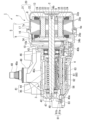
図1は、減速機付きモータ1の斜視図である。図2は、図1のII-II線に沿う断面図である。
減速機付きモータ1は、例えば、車両のワイパー装置の駆動源として用いられる。
図1、図2に示すように、減速機付きモータ1は、電動モータ2と、電動モータ2の回転を減速して出力する減速部3と、電動モータ2の駆動制御を行うコントローラ部4と、を備える。
<Motor with reducer>
FIG. 1 is a perspective view of a
The
As shown in FIGS. 1 and 2, the
以下の説明において、単に「軸方向」という場合は、電動モータ2のシャフト31における中心軸(電動モータ2の回転軸線C)と平行な方向を意味するものとする。単に「周方向」という場合は、シャフト31の周方向(回転方向)を意味するものとする。単に「径方向」という場合は、軸方向及び周方向に直交するシャフト31の径方向を意味するものとする。
In the following description, simply "axial direction" means a direction parallel to the central axis of the
<電動モータ>
電動モータ2は、モータケース5と、モータケース5内に収納されている円筒状のステータ8と、ステータ8の径方向内側に設けられ、ステータ8に対して回転自在に設けられたロータ9と、を備える。電動モータ2は、ステータ8に電力を供給する際にブラシを必要としない、いわゆるブラシレスモータである。
<Electric motor>
The
<モータケース>
モータケース5は、例えばアルミダイキャスト等の放熱性の優れた材料に形成されている。モータケース5は、軸方向に分割可能に構成された第1モータケース6と、第2モータケース7と、からなる。第1モータケース6及び第2モータケース7は、それぞれ有底筒状に形成されている。
第1モータケース6は、底部10が減速部3のギアケース40と接合されるように、このギアケース40と一体成形されている。底部10の径方向中央には、ロータ9のシャフト31が挿通される貫通孔10aが形成されている。
<Motor case>
The
The
第1モータケース6の開口部6aに、径方向外側に向かって張り出す外フランジ部16が形成されているとともに、第2モータケース7の開口部7aに、径方向外側に向かって張り出す外フランジ部17が形成されている。これら外フランジ部16,17同士を突き合わせて内部空間を有するモータケース5を形成している。モータケース5の内部空間に、第1モータケース6及び第2モータケース7に嵌合されるようにステータ8が配置される。
An
<ステータ>
図3は、ステータ8及びロータ9の構成を示し、軸方向からみた図に相当する。
図2、図3に示すように、ステータ8は、径方向に沿う断面形状が円形となる筒状のステータコア本体21と、ステータコア本体21から径方向内側に向かって突出する複数(例えば、本実施形態では6つ)のティース22と、が一体成形されたステータコア20を有している。ステータコア20は、複数の電磁鋼板20pを軸方向に積層することにより形成されている。ステータコア20は、複数の電磁鋼板20pを軸方向に積層して形成する場合に限られるものではなく、例えば、軟磁性粉を加圧成形することにより形成してもよい。
<Stator>
FIG. 3 shows the configuration of the
As shown in FIGS. 2 and 3, the
ティース22は、ステータコア本体21の内周面から径方向に沿って突出するティース本体101と、ティース本体101の径方向内側端から周方向に沿って延びる鍔部102と、が一体成形されたものである。鍔部102は、ティース本体101から周方向両側に延びるように形成されている。周方向で隣り合う鍔部102の間に、スロット19が形成される。
The
ステータコア本体21の内周面及びティース22は、絶縁性を有する樹脂製のインシュレータ23によって覆われている。このインシュレータ23の上から各ティース22にコイル24が巻回されている。各コイル24は、コントローラ部4からの給電により、ロータ9を回転させるための鎖交磁束を生成する。
The inner circumferential surface of the
[第1実施形態]
<ロータ>
図4は、第1実施形態のロータ9を軸方向からみた平面図である。図5は、第1実施形態のロータコア32、主磁石33、及び副磁石34における軸方向の断面図である。図6は、第1実施形態におけるロータ9の分解斜視図である。
図2、図4から図6に示すように、ロータ9は、ステータ8の径方向内側に微小隙間を介して回転自在に設けられている。
[First embodiment]
<Rotor>
FIG. 4 is a plan view of the
As shown in FIGS. 2, 4 to 6, the
ロータ9は、減速部3を構成するウォーム軸44と一体成形されたシャフト31と、シャフト31に嵌合固定されたロータコア32と、ロータコア32の外周面32aに設けられた4つの主磁石33と、ロータコア32における軸方向の両端面(ロータコア本体37における軸方向の両端面)32b,32cに設けられた2つの副磁石(副磁石本体)34と、を備える。このように、電動モータ2において、主磁石33の磁極数とスロット19(ティース22)の数との比は、2:3である。
The
ロータコア32は、複数の電磁鋼板32pを軸方向に積層することにより形成されている。ロータコア32は、複数の電磁鋼板32pを軸方向に積層して形成する場合に限られるものではなく、例えば、軟磁性粉を加圧成形することにより形成してもよい。
ロータコア32は、シャフト31の軸心(回転軸線C)を径方向中心とする円柱状のロータコア本体37と、ロータコア本体37の外周面37aから径方向外側に向かって突出形成された4つのロータ突極35と、が一体成形されたものである。ロータコア本体37の外周面37aが、ロータコア32の外周面32aである。
The
The
ロータコア本体37の径方向中央には、軸方向に貫通するシャフト挿通孔37bが形成されている。シャフト挿通孔37bに、シャフト31が圧入されている。シャフト挿通孔37bに対してシャフト31を挿入とし、接着剤等を用いてシャフト31にロータコア32を固定してもよい。シャフト挿通孔37bには、径方向外側に向かって延びる4つの逃げ溝37cが形成されている。
各逃げ溝37cは、ロータコア本体37の軸方向全体に渡って形成されており、シャフト挿通孔37bに連通されている。各逃げ溝37cは、周方向に等間隔で配置されている。各逃げ溝37cは、例えばシャフト挿通孔37bへのシャフト31の圧入強度を調整する役割を有する。
A
Each
4つのロータ突極35は、周方向に等間隔で配置されている。各ロータ突極35は、径方向で各逃げ溝37cと同一直線上に配置されている。ロータ突極35は、ロータコア32の軸方向全体に延びるように形成されている。ロータ突極35は、周方向で対向する両側面35aが平行となるように形成されている。つまり、ロータ突極35は、周方向の幅寸法が径方向で均一になるように形成されている。
The four rotor
ロータ突極35における径方向の外側端部35bには、周方向中央に、1つの溝部91が軸方向全体に渡って形成されている。溝部91は、径方向内側に向かうに従って周方向の溝幅が徐々に狭くなるように、V溝状に形成されている。この溝部91の周方向両側の角部には、丸面取り部35cが形成されている。丸面取り部35cの径方向最外側端部が、ロータ突極35における径方向の外側端部35bとなる。
In the radially
このように形成されたロータコア32の外周面32a(外周面37a)で、かつ周方向で隣り合う2つのロータ突極35の間は、それぞれ磁石収納部36として構成される。これら磁石収納部36にそれぞれ主磁石33が配置され、例えば接着剤等によりロータコア32に固定される。
The outer
主磁石33は、瓦状に形成されている。より具体的には、主磁石33において、径方向外側の外周面33aの円弧中心Coの位置、及び径方向内側の内周面33bの円弧中心Ciの位置は一致している。これら円弧中心Co,Ciは、回転軸線Cよりも径方向で対応する主磁石33寄りにずれている。主磁石33の外周面33aのうち径方向最外側を通る円の直径と、ロータ突極35における径方向の外側端部35bを通る円の直径とは同一である。
The
主磁石33の内周面33bは、ロータコア本体37の外周面37a(ロータコア32の外周面32a)に当接されている。主磁石33における周方向の両側面は、径方向内側に位置する主磁石側面33cと、主磁石側面33cよりも径方向外側に位置する傾斜面33dと、を有する。主磁石側面33cは、ロータ突極35の側面35aに沿うように形成されている。換言すれば、主磁石側面33cとロータ突極35の側面35aとは、ほぼ平行である。主磁石側面33cと内周面33bとは、円弧面33eを介して滑らかに連結されている。
The inner
傾斜面33dは、主磁石側面33cとの接続部33fから径方向外側に向かうに従ってロータ突極35の側面35aから漸次周方向に離間するように斜めで、かつ平坦に形成されている。接続部33fは、ロータ突極35の径方向中央よりもやや外側よりに配置されている。1つの主磁石33において、周方向両側の傾斜面33dは、主磁石33の周方向中間部と回転軸線Cとを結ぶ直線Sと平行である。このため、2つの傾斜面33d同士も平行である。
The
主磁石33における軸方向の長さL1は、ロータコア32における軸方向の長さL2よりも長い。すなわち、主磁石33は、ロータコア32における軸方向の両端面32b,32cから軸方向の外側に突出した2つのオーバーハング部33g,33hを有する。各オーバーハング部33g,33hにおいて、対応するロータコア32における軸方向の両端面32b,32cからの突出長さL3,L4は、同一である。これら突出長さL3,L4は、以下の説明では、オーバーハング部33g,33hにおける軸方向の長さL3,L4という。
The axial length L1 of the
このような主磁石33は、着磁(磁界)の配向が径方向(厚み方向)に沿ってパラレル配向となるように着磁されている。そして、周方向に磁極が互い違いになるように、主磁石33が配置されている。このため、ロータコア32のロータ突極35は、周方向で隣り合う主磁石33の間、つまり、磁極の境界(極境界)に位置している。
主磁石33としては、例えば、フェライトボンド磁石が用いられる。しかしながら、これに限られるものではなく、主磁石33として、フェライトボンド磁石に代わってフェライト焼結磁石、ネオジムボンド磁石、ネオジム焼結磁石等を適用することも可能である。
Such a
As the
副磁石34は、ロータコア32における軸方向の両端面32b,32cのうち、ロータコア本体37上に配置されている。副磁石34は、ロータコア本体37の形状に対応するように、円環状に形成されている。副磁石34の外径D1は、ロータコア本体37の外径D2とほぼ同一である。このため、副磁石34は、主磁石33のオーバーハング部33g,33hの径方向内側に配置される。副磁石34の外周面34aは、径方向でオーバーハング部33g,33hと対向している。副磁石34の外周面34aは、主磁石33(オーバーハング部33g,33h)の内周面33bに接触している。
The
副磁石34の内径D3は、ロータコア本体37のシャフト挿通孔37bの内径D4よりも若干大きい程度である。副磁石34における軸方向の長さ(厚さ)L5は、主磁石33のオーバーハング部33g,33hにおける軸方向の長さL3,L4と同一である。このため、主磁石33における軸方向の両端面33i,33jと、各副磁石34における軸方向の外側端面34bとは、同一平面上に位置する。副磁石34の外側端面34bとは、副磁石34における軸方向の両端面のうち、ロータコア32とは反対側の端面をいう。
The inner diameter D3 of the
このような副磁石34は、着磁(磁界)の配向が外周面34aに磁極を発生させる極配向である(図4における矢印J参照)。副磁石34の磁極数は、主磁石33の磁極数(主磁石33の個数)と同一である。すなわち、本実施形態では、主磁石33の磁極数は4極あるので、副磁石34の磁極数も4極である。副磁石34の各磁極の位置は、それぞれ主磁石33と径方向で対向する位置である。副磁石34の外周面34aにおける磁極は、主磁石33の外周面33aにおける磁極と同極である。換言すれば、副磁石34の外周面34aにおける磁極は、主磁石33の内周面33bにおける磁極と異極である。
Such a sub-magnet 34 has a polar orientation in which the orientation of magnetization (magnetic field) generates a magnetic pole on the outer
副磁石34としては、例えば、フェライトボンド磁石が用いられる。しかしながら、これに限られるものではなく、副磁石34として、フェライトボンド磁石に代わってフェライト焼結磁石、ネオジムボンド磁石、ネオジム焼結磁石等を適用することも可能である。副磁石34の材質は、主磁石33の材質と異なっていてもよい。
As the
<減速部>
図1、図2に戻り、減速部3は、モータケース5が取り付けられているギアケース40と、ギアケース40内に収納されるウォーム減速機構41と、を備える。ギアケース40は、例えばアルミダイキャスト等の放熱性の優れた材料により形成されている。ギアケース40は、一面に開口部40aを有する箱状に形成されている。ギアケース40は、ウォーム減速機構41を収容するギア収容部42を有する。ギアケース40の側壁40bには、第1モータケース6が一体成形されている箇所に、この第1モータケース6の貫通孔10aとギア収容部42とを連通する開口部43が形成されている。
<Reduction section>
Returning to FIGS. 1 and 2, the
ギアケース40の底壁40cには、円筒状の軸受ボス49が突設されている。軸受ボス49は、ウォーム減速機構41の出力軸48を回転自在に支持するためのものである。軸受ボス49には、内周面に図示しない滑り軸受が設けられている。軸受ボス49の先端内周縁には、図示しないOリングが装着されている。これにより、軸受ボス49を介して外部から内部に塵埃や水が侵入してしまうことが防止される。軸受ボス49の外周面には、複数のリブ52が設けられている。これにより、軸受ボス49の剛性が確保されている。
A
ギア収容部42に収容されたウォーム減速機構41は、ウォーム軸44と、ウォーム軸44に噛合されるウォームホイール45と、により構成されている。ウォーム軸44は、電動モータ2のシャフト31と同軸上に配置されている。ウォーム軸44は、両端がギアケース40に設けられた軸受46,47によって回転自在に支持されている。ウォーム軸44の電動モータ2側の端部は、軸受46を介してギアケース40の開口部43に至るまで突出している。この突出したウォーム軸44の端部と電動モータ2のシャフト31との端部が接合され、ウォーム軸44とシャフト31とが一体化されている。ウォーム軸44とシャフト31は、1つの母材からウォーム軸部分とシャフト部分とを成形することにより一体として形成してもよい。
The
ウォーム軸44に噛合されるウォームホイール45には、このウォームホイール45の径方向中央に出力軸48が設けられている。出力軸48は、ウォームホイール45の回転軸線方向と同軸上に配置されている。出力軸48は、ギアケース40の軸受ボス49を介してギアケース40の外部に突出している。出力軸48の突出した先端には、図示しない電装品と接続されるスプライン48aが形成されている。
A
ウォームホイール45の径方向中央には、出力軸48が突出されている側とは反対側に、図示しないセンサマグネットが設けられている。センサマグネットは、ウォームホイール45の回転位置を検出する回転位置検出部60の一方を構成している。回転位置検出部60の他方を構成する磁気検出素子61は、ウォームホイール45のセンサマグネット側(ギアケース40の開口部40a側)でウォームホイール45と対向配置されているコントローラ部4に設けられている。
A sensor magnet (not shown) is provided at the radial center of the
<コントローラ部>
電動モータ2の駆動制御を行うコントローラ部4は、磁気検出素子61が実装されたコントローラ基板62と、ギアケース40の開口部40aを閉塞するように設けられたカバー63と、を有している。コントローラ基板62が、ウォームホイール45のセンサマグネット側(ギアケース40の開口部40a側)に対向配置されている。
<Controller section>
The
コントローラ基板62は、いわゆるエポキシ基板に複数の導電性のパターン(不図示)が形成されたものである。コントローラ基板62には、電動モータ2のステータコア20から引き出されたコイル24の端末部が接続されているとともに、カバー63に設けられたコネクタ11の端子(不図示)が電気的に接続されている。
The
コントローラ基板62には、磁気検出素子61の他に、コイル24に供給する電流を制御するFET(Field Effect Transistor:電界効果トランジスタ)等のスイッチング素子からなるパワーモジュール(不図示)が実装されている。コントローラ基板62には、このコントローラ基板62に印加される電圧の平滑化を行うコンデンサ(不図示)等が実装されている。
In addition to the
このように構成されたコントローラ基板62を覆うカバー63は、樹脂により形成されている。カバー63は、若干外側に膨出するように形成されている。カバー63の内面側は、コントローラ基板62等を収容するコントローラ収容部56とされている。
カバー63の外周部に、コネクタ11が一体成形されている。コネクタ11は、図示しない外部電源から延びるコネクタが嵌着される。コネクタ11の端子に、コントローラ基板62が電気的に接続されている。これにより、外部電源の電力がコントローラ基板62に供給される。
The
The
カバー63の開口縁には、ギアケース40の側壁40bの端部と嵌め合わされる嵌合部81が突出形成されている。嵌合部81は、カバー63の開口縁に沿う2つの壁81a,81bにより構成されている。これら2つの壁81a,81bの間に、ギアケース40の側壁40bの端部が挿入(嵌め合い)される。これにより、ギアケース40とカバー63との間にラビリンス部83が形成される。ラビリンス部83によって、ギアケース40とカバー63との間から塵埃や水が浸入してしまうことが防止される。ギアケース40とカバー63との固定は、図示しないボルトを締結することにより行われる。
A fitting portion 81 that fits into the end of the
<減速機付きモータの動作>
次に、減速機付きモータ1の動作について説明する。
減速機付きモータ1は、コネクタ11を介してコントローラ基板62に供給された電力が、図示しないパワーモジュールを介して電動モータ2の各コイル24に選択的に供給される。すると、ステータ8(ティース22)に所定の鎖交磁束が形成され、この鎖交磁束とロータ9の主磁石33により形成される有効磁束との間で磁気的な吸引力や反発力が生じる。これにより、ロータ9が継続的に回転する。
<Operation of motor with reducer>
Next, the operation of the
In the
ロータ9が回転すると、シャフト31と一体化されているウォーム軸44が回転し、さらにウォーム軸44に噛合されているウォームホイール45が回転する。そして、ウォームホイール45に連結されている出力軸48が回転し、所望の電装品(例えば、車両に搭載されるワイパ駆動装置)が駆動する。
When the
コントローラ基板62に実装されている磁気検出素子61によって検出されたウォームホイール45の回転位置検出結果は、信号として図示しない外部機器に出力される。図示しない外部機器は、ウォームホイール45の回転位置検出信号に基づいて、図示しないパワーモジュールのスイッチング素子等の切替えタイミングが制御され、電動モータ2の駆動制御が行われる。パワーモジュールの駆動信号の出力や電動モータ2の駆動制御は、コントローラ部4で行われていてもよい。
The rotational position detection result of the
<ロータの作用>
次に、ロータ9の作用について説明する。
ロータ9は、ロータコア32の外周面32aに、主磁石33を配置した、いわゆるSPM(Surface Permanent Magnet)方式のロータである。このため、d軸方向のインダクタンス値が小さくなる。これに加え、ロータ9は、周方向で隣り合う主磁石33間にロータ突極35が設けられている。この結果、ステータ8の鎖交磁束によるq軸方向のインダクタンス値は、ロータ突極35が無い場合と比較して大きくなる。このように、d軸方向とq軸方向とのリラクタンストルクの差も利用してロータ9が回転される。
<Rotor action>
Next, the function of the
The
主磁石33は、ロータコア32における軸方向の両端面32b,32cから軸方向の外側に突出した2つのオーバーハング部33g,33hを有する。このため、ロータ9の有効磁束量が増大される。
ここで、ロータコア32における軸方向の両端面32b,32cには、それぞれ副磁石34が設けられている。副磁石34は、オーバーハング部33g,33hの径方向内側に配置されている。このため、副磁石34によってオーバーハング部33g,33hの内周面33bから流れる磁束が保持される。
The
Here, sub-magnets 34 are provided on both axial end faces 32b, 32c of the
この際、副磁石34は、着磁(磁界)の配向が外周面34aに磁極を発生させる極配向である。このため、1つの主磁石33でのオーバーハング部33g,33hにおける内周面33bの磁束は、副磁石34を通り、N極からS極に向けて(図4における矢印J参照)流れる。そして、周方向で隣の主磁石33(オーバーハング部33g,33h)へと磁束が流れる。このため、主磁石33の漏れ磁束の発生が防止され、主磁石33の磁束が最大限有効活用される。
At this time, the
このように、上述の第1実施形態では、主磁石33は、ロータコア32における軸方向の両端面32b,32cから軸方向の外側に突出した2つのオーバーハング部33g,33hを有する。また、ロータコア32における軸方向の両端面32b,32cには、それぞれ副磁石34が設けられている。副磁石34は、オーバーハング部33g,33hの径方向内側に配置されている。このため、副磁石34によってオーバーハング部33g,33hの内周面33bから流れる磁束を保持できる。よって、主磁石33の磁束を最大限有効活用でき、電動モータ2を効率よく高トルク化できる。
Thus, in the first embodiment described above, the
副磁石34は、着磁(磁界)の配向が外周面34aに磁極を発生させる極配向である。このため、1つのオーバーハング部33g,33hから内周面33bを介して流れる磁束を、副磁石34を介して周方向で隣のオーバーハング部33g,33hへとスムーズに流すことができる。このため、主磁石33の漏れ磁束の発生を確実に防止でき、主磁石33の磁束を最大限有効活用できる。
The
なお、例えば図4、図5に2点鎖線で示す着磁(磁界)の配向J’のように、副磁石34における着磁(磁界)の配向をラジアル配向とした場合、副磁石34によって主磁石33の磁束をある程度保持できるものの、副磁石34の内周面側で漏れ磁束が発生してしまう。このため、副磁石34における着磁(磁界)の配向を極配向とすることにより、主磁石33の漏れ磁束の発生をより確実に防止でき、主磁石33の磁束をさらに最大限有効活用できる。
For example, when the orientation of the magnetization (magnetic field) in the sub-magnet 34 is set to radial orientation, as shown by the magnetization (magnetic field) orientation J' indicated by the two-dot chain line in FIGS. 4 and 5, the sub-magnet 34 Although the magnetic flux of the
ロータコア32は、ロータコア本体37の外周面37aから径方向外側に向かって突出形成された4つのロータ突極35を有している。このため、リラクタンストルクを利用できるので、電動モータ2をさらに効率よく高トルク化できる。
The
ところで、ロータ突極35を有する分、このロータ突極35に流れる磁束の影響でステータコア20に鉄損が生じてしまう。このような構成で、ステータコア20における軸方向の長さよりも例えばロータコア32における軸方向の長さL2を長くしてしまうと、ステータコア20への鉄損の影響が大きくなってしまう。このため、ステータコア20における軸方向の長さに対してロータコア32における軸方向の長さL2を長くすることなく、主磁石33にオーバーハング部33g,33hを設けた。これにより、ロータコア32によるステータコア20への鉄損の影響も小さくできる。
By the way, since the rotor
主磁石33における軸方向の両端面33i,33jと、各副磁石34における軸方向の外側端面34bとは、同一平面上に位置している。このため、主磁石33の磁束をより確実に最大限有効活用できる。すなわち、例えば主磁石33における軸方向の両端面33i,33jよりも各副磁石34における軸方向の外側端面34bが軸方向外側に突出されている場合、副磁石34の突出した箇所から漏れ磁束が発生してしまう。一方、例えば各副磁石34における軸方向の外側端面34bよりも主磁石33における軸方向の両端面33i,33jが軸方向外側に突出されている場合、副磁石34による主磁石33の漏れ磁束の抑制効果が低下してしまう。
Both
ステータ8のステータコア20は、複数の電磁鋼板20pを軸方向に積層することにより形成されている。ロータ9のロータコア32は、複数の電磁鋼板32pを軸方向に積層することにより形成されている。このため、ステータコア20やロータコア32に生じる渦電流損を低減でき、鉄損を低減できる。よって、電動モータ2を効率よく高トルク化できる。
The
主磁石33は、着磁(磁界)の配向が径方向(厚み方向)に沿ってパラレル配向となるように着磁されている。このため、主磁石33における着磁(磁界)の配向がラジアル配向である場合と比較して、電動モータ2のコギングを抑制するとともに、ロータ9の有効磁束を高めることができる。
The
また、主磁石33の外周面33aの円弧中心Coの位置が回転軸線Cよりも径方向で対応する主磁石33寄りにずれている。このため、主磁石33とステータコア20(ティース22)との間の距離は、主磁石33の周方向中から周方向両側面に向かうに従って漸次長くなる。これにより、ステータ8に対してロータ9の磁極の切り替わりが滑らかになり、さらに電動モータ2のコギングを抑制できる。
Further, the position of the arc center Co of the outer
電動モータ2を効率よく高トルク化できるので、国連が主導する持続可能な開発目標(SDGs)の目標7「全ての人々の、安価かつ信頼できる持続可能な近代的エネルギーへのアクセスを確保する」、及び目標9「強靭(レジリエント)なインフラ構築、包摂的かつ持続可能な産業化の促進及びイノベーションの促進を図る」に貢献することが可能となる。
Since the
上述の第1実施形態では、ロータコア32は、ロータコア本体37の外周面37aから径方向外側に向かって突出形成された4つのロータ突極35を有している場合について説明した。主磁石33は、周方向で隣り合うロータ突極35の間のそれぞれに配置されるように、4つ設けられている場合について説明した。しかしながらこれに限られるものではなく、ロータコア32は、ロータ突極35を有さなくてもよい。この場合、主磁石33を円筒状のいわゆるリングマグネットとしてもよい。
In the first embodiment described above, the
[第2実施形態]
次に、図2、図5、図6を援用し、図7、図8に基づいて、本発明の第2実施形態について説明する。第1実施形態と同一態様には、同一符号を付して説明を省略する。
図7は、第2実施形態のロータ209を軸方向からみた平面図である。図7は、前述の図4に対応している。図8は、図7のVIII部拡大図である。
図2、図7、図8に示すように、第2実施形態において、減速機付きモータ1は、電動モータ202と、電動モータ202の回転を減速して出力する減速部3と、電動モータ202の駆動制御を行うコントローラ部4と、を備える点等の基本的構成は、前述の第1実施形態と同様である。
[Second embodiment]
Next, a second embodiment of the present invention will be described with reference to FIGS. 2, 5, and 6, and based on FIGS. 7 and 8. Aspects that are the same as those in the first embodiment are given the same reference numerals and description thereof will be omitted.
FIG. 7 is a plan view of the
As shown in FIGS. 2, 7, and 8, in the second embodiment, the
図7、図8に示すように、第1実施形態と第2実施形態との相違点は、第1実施形態のロータ9における副磁石34の形状と、第2実施形態のロータ209における副磁石234の形状と、が異なる点にある。
より具体的には、副磁石234は、円環状の副磁石本体71と、副磁石本体71の外周面71aから径方向外側に向かって突出形成された4つの磁石突極72と、が一体成形されたものである。
As shown in FIGS. 7 and 8, the difference between the first embodiment and the second embodiment is the shape of the
More specifically, the
副磁石本体71は、ロータコア32における軸方向の両端面32b,32cのうち、ロータコア本体37上(図5参照)に配置されている。副磁石本体71の形状は、第1実施形態における副磁石34の形状と同一である。すなわち、副磁石本体71は、ロータコア本体37の形状に対応するように、円環状に形成されている。副磁石本体71の外径D21は、ロータコア本体37の外径D2(図6参照)とほぼ同一である。このため、副磁石本体71は、主磁石33のオーバーハング部33g,33hの径方向内側に配置される。副磁石本体71の外周面71aは、径方向でオーバーハング部33g,33hと対向している。副磁石34の外周面34aは、主磁石33(オーバーハング部33g,33h)の内周面33bに接触している。
The sub-magnet
4つの磁石突極72は、周方向に等間隔で配置されている。各磁石突極72は、ロータコア32における軸方向の両端面32b,32cのうち、ロータ突極35上に配置されている。磁石突極72は、周方向で対向する両側面72aが平行となるように形成されている。つまり、磁石突極72は、周方向の幅寸法が径方向で均一になるように形成されている。磁石突極72の周方向の幅寸法は、ロータ突極35の周方向の幅寸法と同一である。したがって、磁石突極72の両側面72aは、主磁石33の主磁石側面33cに接触している。
The four magnetic
磁石突極72における径方向の外側端面72bは、おおよそ周方向に沿うように平坦に形成されている。磁石突極72における外側端面72bの位置は、主磁石33における接続部33f(主磁石側面33cの径方向外側端)とロータ突極35の外側端部35bとの間に位置している。
このような副磁石234における着磁(磁界)の配向も、第1実施形態の副磁石34と同様に極配向である(図7における矢印J参照)。
A radially
The orientation of magnetization (magnetic field) in such a sub-magnet 234 is also a polar orientation similarly to the sub-magnet 34 of the first embodiment (see arrow J in FIG. 7).
したがって、上述の第2実施形態によれば、前述の第1実施形態と同様の効果を奏する。これに加え、副磁石234は、磁石突極72を有している。このため、磁石突極72を利用して副磁石234の位置決めを容易に行うことができる。磁石突極72を有する分、副磁石234の体積が増大されるので、副磁石234の有効磁束を増大させることができる。
Therefore, according to the second embodiment described above, the same effects as those of the first embodiment described above are achieved. In addition, the
また、1つのオーバーハング部33g,33hから内周面33bを介して流れる磁束を、副磁石234を介して周方向で隣のオーバーハング部33g,33hへとスムーズに流すことができる。とりわけ、主磁石33における着磁(磁界)の配向がパラレル配向となるように着磁されている場合、1つの主磁石33の主磁石側面33cから流れる磁束を、磁石突極72を介して周方向で隣のオーバーハング部33g,33hへとスムーズに流すことができる(図7における矢印J参照)。このため、主磁石33の漏れ磁束の発生を確実に防止でき、主磁石33の磁束をさらに最大限有効活用できる。
Moreover, the magnetic flux flowing from one
なお、主磁石33における着磁(磁界)の配向をラジアル配向とした場合、主磁石33の周方向両側での配向は、磁石突極72の側面72aとほぼ平行になる。このため、主磁石33の周方向両側からの磁石突極72への磁束の流れは発生しにくい。
Note that when the orientation of the magnetization (magnetic field) in the
ここで、磁石突極72とオーバーハング部33g,33hとが接触する箇所は、主磁石33における接続部33fよりも径方向内側である。すなわち、磁石突極72は、接続部33fよりも径方向内側が主磁石33における漏れ磁束の発生の防止に寄与することになる。本第2実施形態では、磁石突極72における外側端面72bの位置は、主磁石33における接続部33fとロータ突極35の外側端部35bとの間に位置している。このため、副磁石234の体積を無駄に大きくすることなく、1つの主磁石33の周方向両側面から流れる磁束を、副磁石234を介して隣の主磁石33に確実に流すことができる。よって、電動モータ202の製造コストをできる限り抑制できる。
Here, the portion where the magnetic
本発明は上述の実施形態に限られるものではなく、本発明の趣旨を逸脱しない範囲において、上述の実施形態に種々の変更を加えたものを含む。
例えば、上述の実施形態では、減速機付きモータ1は、車両のワイパー装置の駆動源として用いられる場合について説明した。しかしながらこれに限られるものではなく、減速機付きモータ1は、ワイパー装置以外にも、車両に搭載される電装品(例えば、パワーウインドウ、サンルーフ、電動シート等)の駆動源となるものや、その他のさまざまな用途に使用することができる。
The present invention is not limited to the above-described embodiments, but includes various modifications to the above-described embodiments without departing from the spirit of the present invention.
For example, in the embodiment described above, the case where the
上述の実施形態では、副磁石34,234は、主磁石33のオーバーハング部33g,33hに接触しているとして説明した。しかしながらこれに限られるものではなく、完全に接触していなくてもよい。主磁石33や副磁石34,234の製造誤差により、主磁石33と副磁石34,234との間に微小隙間が形成された場合でも、上述の実施形態と同様の効果を奏する。このことは、ロータ突極35と主磁石33とが完全に接触していない場合も同様である。
In the above embodiment, the
上述の実施形態では、主磁石33は、ロータコア32における軸方向の両端面32b,32cから軸方向の外側に突出した2つのオーバーハング部33g,33hを有する場合について説明した。ロータコア32における軸方向の両端面(ロータコア本体37における軸方向の両端面)32b,32cに、それぞれ副磁石34,234が設けられた場合について説明した。しかしながらこれに限られるものではなく、主磁石33は、ロータコア32における軸方向の両端面32b,32cのうち、少なくともいずれか一方から軸方向の外側に突出したオーバーハング部を有していればよい。この場合、副磁石34,234は、オーバーハング部が存在する箇所にのみ設けられていればよい。
In the above embodiment, the
上述の実施形態では、各オーバーハング部33g,33hの突出長さL3,L4は同一である場合について説明した。しかしながらこれに限られるものではなく、各オーバーハング部33g,33hの突出長さL3,L4は同一でなくてもよい。この場合、各オーバーハング部33g,33hの突出長さL3,L4に応じ、副磁石34における軸方向の長さ(厚さ)L5を変更することが望ましい。そして、主磁石33における軸方向の両端面33i,33jと、各副磁石34における軸方向の外側端面34bとを同一平面上に位置させることが望ましい。
In the above-described embodiment, the case where the protrusion lengths L3 and L4 of each
上述の実施形態では、主磁石33における周方向の両側面は、径方向内側に位置する主磁石側面33cと、主磁石側面33cよりも径方向外側に位置する傾斜面33dと、を有する場合について説明した。主磁石側面33cと傾斜面33dとの接続部33fは、ロータ突極35の径方向中央よりもやや外側よりに配置されている場合について説明した。しかしながらこれに限られるものではなく、主磁石33における接続部33fの位置は、任意に設定することができる。また、主磁石33における周方向の両側面全体を、主磁石側面33cとすることも可能である。
In the above-described embodiment, both side surfaces of the
上述の実施形態では、ロータコア32は、4つのロータ突極35を有する場合について説明した。ロータ9は4つの主磁石33を有し、磁極数が4極である場合について説明した。ステータコア20は、6つのティース22を有する場合について説明した。しかしながらこれに限られるものではなく、ロータ突極35、主磁石33の数、及びティース22の数は任意に設定可能である。副磁石34の磁極数は、ロータ9における主磁石33による磁極数に対応するように変更すればよい。
In the above-described embodiment, the
1…減速機付きモータ、2…電動モータ、3…減速部、4…コントローラ部、5…モータケース、6…第1モータケース、6a…開口部、7…第2モータケース、7a…開口部、8…ステータ、9…ロータ、10…底部、10a…貫通孔、11…コネクタ、16…外フランジ部、17…外フランジ部、19…スロット、20…ステータコア、20p…電磁鋼板、21…ステータコア本体、22…ティース、23…インシュレータ、24…コイル、31…シャフト、32…ロータコア、32a…外周面、32b…端面、32c…端面、32p…電磁鋼板、33…主磁石、33a…外周面、33b…内周面、33c…主磁石側面、33d…傾斜面、33e…円弧面、33f…接続部、33g…オーバーハング部、33h…オーバーハング部、33i…端面、33j…端面、34…副磁石、34a…外周面、34b…外側端面、35…ロータ突極、35a…側面、35b…外側端部、35c…丸面取り部、36…磁石収納部、37…ロータコア本体、37a…外周面、37b…シャフト挿通孔、37c…溝、40…ギアケース、40a…開口部、40b…側壁、40c…底壁、41…ウォーム減速機構、42…ギア収容部、43…開口部、44…ウォーム軸、45…ウォームホイール、46…軸受、47…軸受、48…出力軸、48a…スプライン、49…軸受ボス、52…リブ、56…コントローラ収容部、60…回転位置検出部、61…磁気検出素子、62…コントローラ基板、63…カバー、71…副磁石本体、71a…外周面、72…磁石突極、72a…側面、72b…外側端面、81…嵌合部、81a…壁、81b…壁、83…ラビリンス部、91…溝部、101…ティース本体、102…鍔部、202…電動モータ、209…ロータ、234…副磁石
DESCRIPTION OF
Claims (7)
前記ティースに巻回されるコイルと、
前記ステータコアの径方向内側で回転するシャフトと、
前記シャフトに固定され、前記シャフトの回転軸線を径方向中心とするロータコア本体を有するロータコアと、
前記ロータコア本体の外周面に配置された主磁石と、
前記ロータコア本体の前記回転軸線方向の両端面のうちの少なくとも一方の端面に配置され、副磁石本体を有する副磁石と、
を備え、
前記主磁石は、前記ロータコア本体の少なくとも一方の前記端面よりも前記回転軸線方向の外側に突出したオーバーハング部を有し、
前記副磁石本体は、前記オーバーハング部の径方向内側に配置されている
ことを特徴とする電動モータ。 a stator having a stator core including an annular stator core body and a plurality of teeth protruding radially inward from an inner circumferential surface of the stator core body;
a coil wound around the teeth;
a shaft rotating inside the stator core in the radial direction;
a rotor core having a rotor core body fixed to the shaft and centered in a radial direction on the rotational axis of the shaft;
a main magnet disposed on the outer peripheral surface of the rotor core body;
a sub-magnet disposed on at least one of both end faces of the rotor core main body in the direction of the rotation axis, and having a sub-magnet main body;
Equipped with
The main magnet has an overhang portion that protrudes outward in the rotation axis direction from at least one end surface of the rotor core body,
The electric motor is characterized in that the sub-magnet main body is disposed radially inside the overhang portion.
ことを特徴とする請求項1に記載の電動モータ。 The electric motor according to claim 1, wherein the sub-magnet main body has a polar orientation in which a magnetic pole is generated on an outer circumferential surface facing the overhang portion.
前記主磁石は、周方向で隣り合う前記ロータ突極の間のそれぞれに配置されている
ことを特徴とする請求項1又は請求項2に記載の電動モータ。 The rotor core has a plurality of rotor salient poles formed to protrude radially outward from the outer peripheral surface of the rotor core main body,
The electric motor according to claim 1 or 2, wherein the main magnet is arranged between each of the rotor salient poles adjacent in the circumferential direction.
前記複数の磁石突極は、それぞれ前記複数のロータ突極における前記回転軸線方向の端面に配置されている
ことを特徴とする請求項3に記載の電動モータ。 The sub-magnet has a plurality of salient magnetic poles formed to protrude radially outward from the outer peripheral surface of the sub-magnet main body,
4. The electric motor according to claim 3, wherein the plurality of magnetic salient poles are respectively arranged on end faces of the plurality of rotor salient poles in the direction of the rotation axis.
前記主磁石側面は、前記磁石突極の周方向側面に沿うように延在され、かつ周方向で前記磁石突極の前記周方向側面と対向しており、
前記磁石突極の径方向外側の端面は、前記主磁石側面の径方向外側端と前記ロータ突極の径方向外側端との間に位置している
ことを特徴とする請求項4に記載の電動モータ。 The main magnet has a main magnet side surface formed on at least a portion including the radially inner side of both circumferential side surfaces,
The main magnet side surface extends along the circumferential side surface of the salient magnetic pole, and faces the circumferential side surface of the salient magnetic pole in the circumferential direction,
5. The radially outer end face of the salient magnet pole is located between the radially outer end of the main magnet side surface and the radially outer end of the rotor salient pole. electric motor.
ことを特徴とする請求項1又は請求項2に記載の電動モータ。 The electric motor according to claim 1 or 2, wherein an end face of the main magnet in the direction of the rotation axis and an outer end face of the sub magnet in the direction of the rotation axis are located on the same plane. motor.
ことを特徴とする請求項1又は請求項2に記載の電動モータ。 The electric motor according to claim 1 or 2, wherein the stator core and the rotor core are formed by laminating a plurality of electromagnetic steel sheets in the direction of the rotation axis.
Priority Applications (1)
| Application Number | Priority Date | Filing Date | Title |
|---|---|---|---|
| JP2022071637A JP2023161321A (en) | 2022-04-25 | 2022-04-25 | electric motor |
Applications Claiming Priority (1)
| Application Number | Priority Date | Filing Date | Title |
|---|---|---|---|
| JP2022071637A JP2023161321A (en) | 2022-04-25 | 2022-04-25 | electric motor |
Publications (1)
| Publication Number | Publication Date |
|---|---|
| JP2023161321A true JP2023161321A (en) | 2023-11-07 |
Family
ID=88650143
Family Applications (1)
| Application Number | Title | Priority Date | Filing Date |
|---|---|---|---|
| JP2022071637A Pending JP2023161321A (en) | 2022-04-25 | 2022-04-25 | electric motor |
Country Status (1)
| Country | Link |
|---|---|
| JP (1) | JP2023161321A (en) |
-
2022
- 2022-04-25 JP JP2022071637A patent/JP2023161321A/en active Pending
Similar Documents
| Publication | Publication Date | Title |
|---|---|---|
| JP2008131683A (en) | Axial air gap type motor | |
| US20150295457A1 (en) | Rotor and motor | |
| US11289960B2 (en) | Motor and brushless wiper motor | |
| WO2018128165A1 (en) | Rotor and electric motor | |
| US11901779B2 (en) | Motor and brushless wiper motor | |
| US20210384783A1 (en) | Rotor, motor and brushless motor | |
| CN111919359B (en) | Motor and brushless wiper motor | |
| JP7077153B2 (en) | Motors and brushless wiper motors | |
| WO2019202915A1 (en) | Motor, brushless wiper motor, and method for driving motor | |
| JP2023161321A (en) | electric motor | |
| JP2020078177A (en) | Rotor, motor and brushless wiper motor | |
| JP7431076B2 (en) | motor | |
| JP2023161742A (en) | electric motor | |
| JP6655500B2 (en) | Electric motor | |
| JP2023173172A (en) | electric motor | |
| JP7122944B2 (en) | Rotors, motors and brushless wiper motors | |
| JP7462533B2 (en) | Rotor, motor and brushless wiper motor | |
| KR102220049B1 (en) | Stator core and motor including stator core | |
| JP7287825B2 (en) | motor and wiper motor | |
| KR101405973B1 (en) | Motor | |
| JP2023049370A (en) | electric motor | |
| KR20100005890A (en) | Motor | |
| JP2009055698A (en) | Rotor for permanent magnet type motor | |
| JP2023060598A (en) | rotor and motor | |
| KR101448646B1 (en) | Motor |