KR20100005890A - Motor - Google Patents
Motor Download PDFInfo
- Publication number
- KR20100005890A KR20100005890A KR1020080065990A KR20080065990A KR20100005890A KR 20100005890 A KR20100005890 A KR 20100005890A KR 1020080065990 A KR1020080065990 A KR 1020080065990A KR 20080065990 A KR20080065990 A KR 20080065990A KR 20100005890 A KR20100005890 A KR 20100005890A
- Authority
- KR
- South Korea
- Prior art keywords
- rotor
- motor
- stator
- center
- magnet insertion
- Prior art date
Links
Images


Classifications
-
- H—ELECTRICITY
- H02—GENERATION; CONVERSION OR DISTRIBUTION OF ELECTRIC POWER
- H02K—DYNAMO-ELECTRIC MACHINES
- H02K1/00—Details of the magnetic circuit
- H02K1/06—Details of the magnetic circuit characterised by the shape, form or construction
- H02K1/22—Rotating parts of the magnetic circuit
- H02K1/27—Rotor cores with permanent magnets
- H02K1/2706—Inner rotors
- H02K1/272—Inner rotors the magnetisation axis of the magnets being perpendicular to the rotor axis
- H02K1/274—Inner rotors the magnetisation axis of the magnets being perpendicular to the rotor axis the rotor consisting of two or more circumferentially positioned magnets
- H02K1/2753—Inner rotors the magnetisation axis of the magnets being perpendicular to the rotor axis the rotor consisting of two or more circumferentially positioned magnets the rotor consisting of magnets or groups of magnets arranged with alternating polarity
- H02K1/276—Magnets embedded in the magnetic core, e.g. interior permanent magnets [IPM]
-
- H—ELECTRICITY
- H02—GENERATION; CONVERSION OR DISTRIBUTION OF ELECTRIC POWER
- H02K—DYNAMO-ELECTRIC MACHINES
- H02K1/00—Details of the magnetic circuit
- H02K1/06—Details of the magnetic circuit characterised by the shape, form or construction
- H02K1/12—Stationary parts of the magnetic circuit
- H02K1/14—Stator cores with salient poles
-
- H—ELECTRICITY
- H02—GENERATION; CONVERSION OR DISTRIBUTION OF ELECTRIC POWER
- H02K—DYNAMO-ELECTRIC MACHINES
- H02K1/00—Details of the magnetic circuit
- H02K1/06—Details of the magnetic circuit characterised by the shape, form or construction
- H02K1/22—Rotating parts of the magnetic circuit
- H02K1/27—Rotor cores with permanent magnets
- H02K1/2706—Inner rotors
- H02K1/272—Inner rotors the magnetisation axis of the magnets being perpendicular to the rotor axis
- H02K1/274—Inner rotors the magnetisation axis of the magnets being perpendicular to the rotor axis the rotor consisting of two or more circumferentially positioned magnets
- H02K1/2753—Inner rotors the magnetisation axis of the magnets being perpendicular to the rotor axis the rotor consisting of two or more circumferentially positioned magnets the rotor consisting of magnets or groups of magnets arranged with alternating polarity
- H02K1/276—Magnets embedded in the magnetic core, e.g. interior permanent magnets [IPM]
- H02K1/2766—Magnets embedded in the magnetic core, e.g. interior permanent magnets [IPM] having a flux concentration effect
-
- H—ELECTRICITY
- H02—GENERATION; CONVERSION OR DISTRIBUTION OF ELECTRIC POWER
- H02K—DYNAMO-ELECTRIC MACHINES
- H02K29/00—Motors or generators having non-mechanical commutating devices, e.g. discharge tubes or semiconductor devices
- H02K29/03—Motors or generators having non-mechanical commutating devices, e.g. discharge tubes or semiconductor devices with a magnetic circuit specially adapted for avoiding torque ripples or self-starting problems
-
- H—ELECTRICITY
- H02—GENERATION; CONVERSION OR DISTRIBUTION OF ELECTRIC POWER
- H02K—DYNAMO-ELECTRIC MACHINES
- H02K2213/00—Specific aspects, not otherwise provided for and not covered by codes H02K2201/00 - H02K2211/00
- H02K2213/03—Machines characterised by numerical values, ranges, mathematical expressions or similar information
Landscapes
- Engineering & Computer Science (AREA)
- Power Engineering (AREA)
- Iron Core Of Rotating Electric Machines (AREA)
- Permanent Field Magnets Of Synchronous Machinery (AREA)
- Permanent Magnet Type Synchronous Machine (AREA)
Abstract
Description
본 발명은 모터에 관한 것으로, 더욱 상세하게는 회전자의 구조를 변경하여 토크 리플을 줄임으로써 소음 및 진동을 감소시키고 효율을 증가시킬 수 있는 모터에 관한 것이다.The present invention relates to a motor, and more particularly to a motor that can reduce the noise and vibration and increase the efficiency by changing the structure of the rotor to reduce the torque ripple.
일반적으로 모터는 전기에너지를 기계에너지로 바꾸는 장치로서, 냉장고, 압축기 등과 같이 다양한 기계에 사용된다.In general, a motor converts electrical energy into mechanical energy and is used in various machines such as a refrigerator and a compressor.
이러한 모터의 종류 중 하나로 브러쉬리스 모터가 있다.One type of motor is a brushless motor.
브러쉬리스 모터는 모터에서 브러쉬와 정류자를 없애고 전자적인 정류 기구를 설치하여 기계적 또는 전기적인 노이즈를 발생시키지 않을 뿐만 아니라 저속부터 고속까지 다양한 속도로 모터의 제어가 가능하다. 또한, 다극으로 회전토크가 안정적이며, 긴 수명을 가지는 장점을 가진다.The brushless motor eliminates brushes and commutators from the motor, installs electronic commutation mechanisms, and does not generate mechanical or electrical noise, and can control the motor at various speeds from low speed to high speed. In addition, the multi-pole rotary torque is stable, has the advantage of long life.
도 1 및 도 2는 종래의 브러쉬리스 모터를 도시한 것으로서, 도 1은 종래의 브러쉬리스 모터의 종단면도이고, 도 2는 종래의 브러쉬리스 모터의 횡단면도를 도시한 것이다.1 and 2 show a conventional brushless motor, FIG. 1 is a longitudinal sectional view of a conventional brushless motor, and FIG. 2 shows a cross sectional view of a conventional brushless motor.
도 1에 도시된 바와 같이 종래의 브러쉬리스 모터는 소정의 내부 공간을 갖 는 하우징(10)과 상기 하우징(10)의 내부에 고정 결합되는 고정자(20)와, 상기 고정자(20)의 내부에 회전 가능하도록 삽입되는 회전자(30)와, 상기 회전자(30)의 내부에 압입 고정됨과 아울러 각 베어링(41)에 회전 가능하게 고정되는 회전축(40)을 구비한다.As shown in FIG. 1, the conventional brushless motor includes a
도 2에 도시된 바와 같이 상기 고정자(20)는 내주면에 돌출 형성된 복수개의 티스(21)를 구비하고, 각 티스(21) 사이에 요홈지게 형성된 슬롯(22)이 형성되며, 상기 티스(21)의 내측 양단에 돌출 형성된 폴슈(23) 사이에 슬롯 개구부(24)가 형성된 고정자 코어(25)와, 상기 고정자 코어의 티스(21)에 권선되는 고정자 코일(26)로 구성된다.As shown in FIG. 2, the
상기 회전자(30)는 중심부에 회전축(40)을 압입 고정하기 위한 축공(31)이 형성되며, 상기 축공(31) 외측에 영구자석(50)을 고정하기 위한 자석 삽입공(32)이 원주 방향으로 4개가 형성된 회전자 코어(35)를 적층시켜 결합되도록 형성된다.The
마주보는 자석 삽입공(32)에 고정된 영구자석(50)끼리는 서로 동일 극성을 갖도록 안착되고, 인접한 자석 삽입공(32)에 고정된 영구자석(50)끼리는 서로 다른 극성을 갖도록 안착된다.
이와 같은 구성에 있어서, 종래 모터의 작동은 상기 고정자(20)의 각 티스(21)에 권선된 고정자 코일에 전류가 인가되면, 각 티스(21)가 N극과 S극의 교번 극성을 갖게 되고 상기 고정자(20)의 티스(21)에 인접한 회전자(30)의 영구자석(50)과의 자기 플럭스에 의하여 회전자(30)가 회전한다.In such a configuration, in the operation of the conventional motor, when a current is applied to the stator coil wound around each
이때 N극의 극성을 갖는 영구자석(50)과 N극의 극성을 갖는 티스(21)가 접하 는 부분에서는 자력이 반발하여 서로 미는 힘인 척력이 발생하게 되고, 인접한 N극의 영구자석(50)과 S극의 극성을 띄는 티스(21)가 접하는 부분에서는 활발한 자기 플럭스가 형성되어 자속 밀도가 집중되어 서로 잡아당기려는 인력이 작용하게 된다.At this time, in the portion where the
그러나, 상기와 같은 모터에서 회전자(30)가 회전하여 극이 변할 때 코깅 토크(cogging torque)나 토크 리플(torque ripple)이 크게 발생하여 소음과 진동이 발생하고, 모터의 효율이 저하되는 문제점이 있었다.However, when the
본 발명은 상기와 같은 문제점을 해결하기 위한 것으로, 회전자의 구조를 변경하여 토크 리플을 줄임으로써 소음 및 진동을 줄이고, 효율을 높일 수 있는 모터를 제공한다.The present invention is to solve the above problems, to provide a motor that can reduce the noise and vibration by increasing the torque ripple by changing the structure of the rotor, to increase the efficiency.
본 발명에 따른 모터는 하우징과, 상기 하우징 내부에 안착되며 코일이 권선되는 복수개의 티스를 구비하는 고정자와, 상기 고정자의 내부에 수용되며 상기 티스와 자기 플럭스에 의하여 회전력을 발생시키는 복수개의 영구자석이 삽입 고정되는 복수개의 자석 삽입공이 마련되는 회전자를 구비하는 모터에 있어서, 상기 회전자의 외주면에는 상기 직선부와 곡선부가 교대로 형성된다.The motor according to the present invention includes a stator having a housing, a plurality of teeth seated inside the housing, and a coil wound thereon, and a plurality of permanent magnets received inside the stator to generate rotational force by the teeth and the magnetic flux. In a motor having a rotor provided with a plurality of magnet insertion holes to be inserted and fixed, the straight portion and the curved portion are alternately formed on the outer circumferential surface of the rotor.
또한, 상기 자석 삽입공은 중앙부가 상기 회전자의 중심을 향하도록 절곡된 V자 형상을 가진다.In addition, the magnetic insertion hole has a V-shape bent so that the center portion toward the center of the rotor.
또한, 상기 직선부는 상기 각 영구자석의 외측 단부에 대응하는 부분에 구비되는 것이 바람직하다.In addition, the straight portion is preferably provided in a portion corresponding to the outer end of each of the permanent magnets.
또한, 상기 회전자의 중심에서 상기 직선부의 중심과 상기 직선부의 단부로 연장되는 직선이 이루는 각을 θ1라 할때, 23°≤θ1≤ 25°를 만족하는 것이 바람직하다.Further, when the angle formed by the straight line extending from the center of the rotor to the end of the straight portion at the center of the rotor is θ1, it is preferable to satisfy 23 ° ≦ θ1 ≦ 25 °.
또한, 상기 곡선부의 길이가 상기 직선부의 길이보다 긴 것이 바람직하다.Further, it is preferable that the length of the curved portion is longer than the length of the straight portion.
또한, 상기 회전자의 중심에서 서로 이웃하는 2개의 자석 삽입공의 중앙으로 연장되는 직선을 Q축이라고 할 때, 상기 Q축과 상기 회전자의 중심에서 상기 Q축과 가까운 상기 직선부의 단부로 연장되는 직선이 이루는 각을 θ2라 할 때, 1.5°≤θ2≤ 3°를 만족하는 것이 바람직하다.In addition, when a straight line extending from the center of the rotor to the center of two magnet insertion holes adjacent to each other is called the Q axis, the straight line extending from the center of the Q axis and the rotor to the end of the straight portion closer to the Q axis When the angle formed by the straight line is? 2, it is preferable to satisfy 1.5 ° ≤θ2≤3 °.
또한, 상기 하나의 자석 삽입공에는 2개의 영구자석이 삽입되는 것이 바람직하다.In addition, it is preferable that two permanent magnets are inserted into the one magnet insertion hole.
또한, 상기 2개의 영구자석이 서로 이루는 각을 θ3라고 할 때, 136°≤θ3≤ 144°를 만족하는 것이 바람직하다.In addition, when the angle formed by the two permanent magnets is θ3, it is preferable to satisfy 136 ° ≦ θ3 ≦ 144 °.
또한, 상기 회전자가 4개의 극을 갖도록 상기 회전자는 4개의 자석 삽입공을 구비되는 것이 바람직하다.In addition, the rotor is preferably provided with four magnetic insertion holes so that the rotor has four poles.
또한, 상기 코일은 분산권으로 권선되는 것이 바람직하다.In addition, the coil is preferably wound in a dispersion zone.
본 발명에 따른 모터에 의하면 회전자의 구조, 특히 회전자 코어의 원주면의 형상을 변경함으로써 토크 리플을 줄일 수 있으며, 이에 따라 모터의 소음 및 진동을 줄일 수 있을 뿐만 아니라 모터의 효율을 증가시킬 수 있다.According to the motor according to the present invention, by changing the structure of the rotor, in particular the shape of the circumferential surface of the rotor core can reduce the torque ripple, thereby reducing the noise and vibration of the motor as well as increase the efficiency of the motor Can be.
이하에서는 첨부된 도면을 참조하여 본 발명의 바람직한 일 실시예에 따른 모터에 대해 설명한다.Hereinafter, a motor according to an exemplary embodiment of the present invention will be described with reference to the accompanying drawings.
도 3에 도시된 바와 같이, 본 발명에 따른 모터는 하우징(100)과, 상기 하우징(100)의 내부에 고정 결합되는 고정자(200)와, 상기 고정자(200)의 내부에 회전 가능하도록 삽입되는 회전자(300)와, 상기 회전자(300)의 내부에 압입 고정됨과 아 울러 회전자(300)의 회전력을 외부로 전달하는 회전축(미도시)을 구비한다.As shown in FIG. 3, the motor according to the present invention includes a
고정자(200)는 고정자 코어(210)와 티스(211)를 포함하여 이루어진다.The
상기 고정자 코어(210)는 도시된 바와 같이 환형으로 이루어질 수 있으며, 자속 경로를 형성하게 된다. 그리고, 상기 티스(211)는 상기 고정자 코어(210)의 반경 방향으로 돌출되며, 상기 티스(211)에 고정자 코일(220)이 권선된다. 도시된 모터는 일례로 고정자 코어(210)의 내부에 회전자(300)가 위치하는 타입의 모터이므로, 상기 티스(211)는 상기 고정자 코어(210)의 반경 방향 내측으로 돌출되어 형성된다.The
상기 고정자 코어(210)는 단위 고정자 코어를 적층하여 형성될 수 있다. 얇은 단위 고정자 코어를 복수 개 적층하여 소정 높이를 갖는 고정자 코어(210)를 형성할 수 있다.The
이러한 적층 형태로 고정자 코어(210)를 형성하는 경우 상기 단위 고정자 코어들을 일체로 결합시킬 필요가 있다. 일체로 형성된 하나의 고정자 코어(210)를 형성할 필요가 있다. 따라서, 이러한 단위 고정자 코어들을 결합시키기 위한 코킹(caulking)부가 필요하다. 이러한 코킹부는 고정자 코어(210)의 상, 하부를 관통하여 형성되는 것이 바람직하다.When the
상기 고정자 코일(220)은 상기 티스(211)에 분산권으로 권선된다. 이때 고정자(200)는 4개의 극을 가져 4개의 자속 경로를 형성하도록 권선된다. 즉, 환형을 이루는 복수개의 티스(211)를 4등분하여 하나의 등분이 하나의 극을 가지도록 고정자 코일(220)이 권선된다.The
상기 티스(211)에 권선되는 고정자 코일(220)에 전원이 인가되면, 하나의 극과 이웃하는 극에는 각각 N극과 S극의 자극이 교대로 형성된다. 이때, 티스(211)를 중심으로 자극이 형성되는데, 상기 티스(211)와 티스(211) 사이의 거리가 멀어질수록 누설되는 자속이 증가한다. 따라서, 누설 자속을 최소화하기 위하여 상기 티스(211)의 선단부에는 마주보는 회전자(300)의 외주면과 부합되도록 양측 원주 방향으로 일정 길이 연장되도록 폴슈(212)가 형성되는 것이 바람직하다 이를 통해 이웃하는 티스(211) 사이에 발생하는 누설 자속을 최소화할 수 있다.When power is applied to the
상기와 같이 형성된 고정자(200)를 하우징(100)에 고정시키기 위해 상기 고정자(200)는 복수개의 고정부(250)를 구비한다. 상기 각 고정부(250)는 서로 90° 간격을 가지도록 형성될 수 있다. 그리고 각 고정부(250) 사이에는 냉매와 같은 유체가 순환할 수 있도록 에어갭(260)이 형성된다.In order to fix the
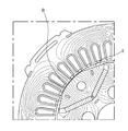
도 4는 도 3에서 회전자를 확대하여 도시한 도면이다.FIG. 4 is an enlarged view of the rotor in FIG. 3.
상기 회전자(300)는 중심부에 회전축을 압입 고정하기 위한 축공(301) 및 상기 축공(301)에 각각 2개의 영구자석(350)이 삽입되는 4개의 'V'자 형상의 자석 삽입공(302)이 원주 방향을 따라 마련된 회전자 코어(303)를 적층하여 형성된다.The
서로 이웃하는 자석 삽입공(302)에 삽입되는 영구자석(350)은 서로 다른 극성을 갖고, 서로 마주보는 자석 삽입공(302)에 삽입되는 영구자석(350)은 서로 동일한 극성을 갖는다.The
그리고, 도 4에 도시된 바와 같이 자석 삽입공(302)에 삽입되는 영구자석(350)의 외측 단부에 대응하는 부분에 직선부(310)가 형성되고, 자석 삽입 공(302)에 삽입되는 영구자석(350)의 내측 단부에 대응하는 부분에는 곡선부(320)가 형성된다.4, a
도 5는 도 4에 도시된 회전자를 채용한 모터에서 발생하는 자기 플럭스를 나타낸 것이다.FIG. 5 shows the magnetic flux generated in the motor employing the rotor shown in FIG. 4.
도 5에 도시된 바와 같이 직선부(310)와 고정자(200) 사이의 공극(A)에 형성된 자기 플럭스의 밀도는 곡선부(320)와 고정자(200) 사이의 공극(B)에 형성된 자기 플럭스의 밀도보다 낮은 것을 알 수 있다.As shown in FIG. 5, the density of the magnetic flux formed in the gap A between the
따라서, 회전자(300)가 회전할 때 자극이 바뀌는 부분에서 극격한 자극의 변화로 인해 회전자(300)와 회전축에서 발생하는 코깅 토크나 토크 리플을 감소시킬 수 있다.Therefore, when the
본 발명인은 토크 리플을 최소화하기 위한 최적의 직선부(310) 및 곡선부(320)를 설계하기 위해 노력하였다.The inventors have endeavored to design the optimum
도 4에서 상기 회전자의 중심에서 상기 직선부의 양단부로 각각 연장되는 2개의 직선이 이루는 각을 θ1으로 하였다. 상기 회전자의 중심에서 서로 이웃하는 2개의 자석 삽입공의 중앙으로 연장되는 직선을 Q축이라고 할 때, 상기 Q축과 상기 회전자의 중심(O)에서 상기 Q축과 가까운 상기 직선부의 단부로 연장되는 직선이 이루는 각을 θ2로 하였다. 그리고, 자석 삽입공(302)에 삽입되는 상기 2개의 영구자석이 서로 이루는 각을 θ3라고 하였다.In FIG. 4, an angle formed by two straight lines extending from the center of the rotor to both ends of the straight portion is θ1. When a straight line extending from the center of the rotor to the center of two magnet insertion holes adjacent to each other is referred to as the Q axis, the Q axis and the center portion of the rotor O to the end portion of the straight portion close to the Q axis The angle formed by the straight line extending was set to θ2. The angle formed by the two permanent magnets inserted into the
그리고, 상기 θ1, θ2, θ3의 값에 따른 토크 리플의 변화에 대해 실험하였다.Then, the change in the torque ripple according to the values of θ1, θ2, and θ3 was tested.
도 6은 θ1의 변화에 따른 토크 리플의 변화를 나타낸 실험 데이터이다.6 is experimental data showing a change in torque ripple with a change in θ1.
도 6에 도시된 바와 같이 θ1값이 증가함에 따라 토크 리플은 점차 감소하다가 대략 24°를 기점으로 다시 증가하는 것을 알 수 있다.As shown in FIG. 6, the torque ripple gradually decreases as the value of θ1 increases, and then increases again from about 24 °.
따라서, 23°≤θ1≤ 25°범위를 만족하는 것이 바람직하다는 것을 알 수 있다.Thus, it can be seen that it is desirable to satisfy the
도 7은 θ2의 변화에 따른 토크 리플의 변화를 나타낸 실험 데이터이다.7 is experimental data showing a change in torque ripple with a change in θ2.
도 7에 도시된 바와 같이 θ2값이 증가함에 따라 토크 리플은 점차 감소하다가 대략 2.5°를 기점으로 다시 증가하는 것을 알 수 있다.As shown in FIG. 7, the torque ripple gradually decreases as the value of
따라서, 1.5°≤θ2≤ 3.5°범위를 만족하는 것이 바람직하다는 것을 알 수 있다.Accordingly, it can be seen that it is desirable to satisfy the range of 1.5 ° ≦ θ2 ≦ 3.5 °.
도 8은 θ3의 변화에 따른 토크 리플의 변화를 나타낸 실험 데이터이다.8 is experimental data showing a change in torque ripple with a change in θ3.
도 8에 도시된 바와 같이 θ3가 대략 140°일때 까지 토크 리플이 감소하지만 140°를 넘어서면 다시 증가하는 것을 볼 수 있다. 즉, 토크 리플의 허용 임계치를 14%로 설정하였을 때, 상기 허용 임계치를 만족하는 θ2의 값은 136°이상, 144°이하인 것을 알 수 있다.As shown in FIG. 8, the torque ripple decreases until θ3 is approximately 140 °, but increases again beyond 140 °. That is, when the tolerance threshold of torque ripple is set to 14%, it can be seen that the value of θ2 satisfying the tolerance threshold is 136 ° or more and 144 ° or less.
따라서, 토크 리플을 감소시키기 위해 136°≤θ3≤ 144°를 만족하도록 영구 자석(320)의 설치 위치를 설계하는 바람직하다는 것을 알 수 있다.Thus, it can be seen that it is desirable to design the installation position of the
이상에서 살펴본 바와 같이 본 발명의 일 실시예에 따른 모터에 의하면 회전자 구조의 최적의 설계를 통해 토크 리플을 감소시킬 수 있다.As described above, according to the motor according to the exemplary embodiment of the present invention, torque ripple can be reduced through an optimal design of the rotor structure.
도 1은 종래 모터의 종단면도.1 is a longitudinal cross-sectional view of a conventional motor.
도 2는 도 1에 도시된 모터의 횡단면도.2 is a cross-sectional view of the motor shown in FIG. 1.
도 3은 본 발명의 일 실시예에 따른 모터의 횡단면도.3 is a cross-sectional view of a motor according to an embodiment of the present invention.
도 4는 도 3에서 일부를 확대하여 도시한 확대도.4 is an enlarged view of a portion of FIG. 3 in an enlarged manner;
도 5는 도 3에 도시된 모터에 발생하는 자기 플럭스를 나타낸 도면.FIG. 5 shows a magnetic flux generated in the motor shown in FIG. 3. FIG.
도 6은 θ1의 변화에 따른 토크 리플의 변화를 나타낸 실험 데이터.6 is experimental data showing a change in torque ripple with a change in θ1.
도 7은 θ2의 변화에 따른 토크 리플의 변화를 나타낸 실험 데이터.7 is experimental data showing a change in torque ripple with a change in θ2.
도 8은 θ3의 변화에 따른 토크 리플의 변화를 나타낸 실험 데이터.8 is experimental data showing a change in torque ripple with a change in θ3.
** 도면의 주요 부분에 대한 설명 **** Description of the main parts of the drawing **
100: 하우징 200: 고정자100: housing 200: stator
300: 회전자 302: 자석 삽입공300: rotor 302: magnetic insertion hole
303: 회전자 코어 320: 회전자303: rotor core 320: rotor
Claims (10)
Priority Applications (1)
| Application Number | Priority Date | Filing Date | Title |
|---|---|---|---|
| KR1020080065990A KR20100005890A (en) | 2008-07-08 | 2008-07-08 | Motor |
Applications Claiming Priority (1)
| Application Number | Priority Date | Filing Date | Title |
|---|---|---|---|
| KR1020080065990A KR20100005890A (en) | 2008-07-08 | 2008-07-08 | Motor |
Publications (1)
| Publication Number | Publication Date |
|---|---|
| KR20100005890A true KR20100005890A (en) | 2010-01-18 |
Family
ID=41815159
Family Applications (1)
| Application Number | Title | Priority Date | Filing Date |
|---|---|---|---|
| KR1020080065990A KR20100005890A (en) | 2008-07-08 | 2008-07-08 | Motor |
Country Status (1)
| Country | Link |
|---|---|
| KR (1) | KR20100005890A (en) |
Cited By (2)
| Publication number | Priority date | Publication date | Assignee | Title |
|---|---|---|---|---|
| KR20160001491A (en) | 2014-06-27 | 2016-01-06 | (주) 엠투다이아몬드 | Mounting structure for Gem ornaments |
| US20210152039A1 (en) * | 2018-08-03 | 2021-05-20 | Mitsubishi Electric Corporation | Stator, motor, compressor, and refrigerating and air conditioning apparatus |
-
2008
- 2008-07-08 KR KR1020080065990A patent/KR20100005890A/en active Search and Examination
Cited By (2)
| Publication number | Priority date | Publication date | Assignee | Title |
|---|---|---|---|---|
| KR20160001491A (en) | 2014-06-27 | 2016-01-06 | (주) 엠투다이아몬드 | Mounting structure for Gem ornaments |
| US20210152039A1 (en) * | 2018-08-03 | 2021-05-20 | Mitsubishi Electric Corporation | Stator, motor, compressor, and refrigerating and air conditioning apparatus |
Similar Documents
| Publication | Publication Date | Title |
|---|---|---|
| US6774523B2 (en) | Electric motor | |
| KR20170039606A (en) | Brushless motor | |
| KR101103363B1 (en) | Stator and Motor Having the Same | |
| KR20110058057A (en) | Permanent magnet type motor | |
| KR102491659B1 (en) | Interior permanent magnet type bldc motor | |
| KR100706193B1 (en) | Insulator for motor stator | |
| JP2012114970A (en) | Interior permanent magnet motor | |
| KR20100005890A (en) | Motor | |
| JP4770434B2 (en) | motor | |
| KR20190074467A (en) | A Motor having split stator | |
| KR20050116677A (en) | Brushless dc motor | |
| KR20100068871A (en) | Stator for electric machines using rectangular copper wire | |
| KR101448646B1 (en) | Motor | |
| KR101405973B1 (en) | Motor | |
| KR101448647B1 (en) | Motor | |
| JP6435838B2 (en) | Rotating electric machine rotor and rotating electric machine including the same | |
| WO2017042886A1 (en) | Permanent magnet-type rotating electric motor and compressor using same | |
| JP2014107951A (en) | Motor | |
| KR20170039603A (en) | Brushless Motor | |
| KR101448649B1 (en) | Motor | |
| KR102526938B1 (en) | Rotor for an interior permanent magnet motor and a motor with the same | |
| KR200413099Y1 (en) | Insulator for motor stator | |
| KR100511272B1 (en) | Structure of rotor for magnetic type motor | |
| KR100698158B1 (en) | A Motor | |
| KR100436147B1 (en) | Interior permanent magnet type motor |
Legal Events
| Date | Code | Title | Description |
|---|---|---|---|
| A201 | Request for examination | ||
| E902 | Notification of reason for refusal | ||
| AMND | Amendment | ||
| E601 | Decision to refuse application | ||
| AMND | Amendment | ||
| J201 | Request for trial against refusal decision | ||
| B601 | Maintenance of original decision after re-examination before a trial |