JP3620358B2 - child seat - Google Patents
child seat Download PDFInfo
- Publication number
- JP3620358B2 JP3620358B2 JP21899399A JP21899399A JP3620358B2 JP 3620358 B2 JP3620358 B2 JP 3620358B2 JP 21899399 A JP21899399 A JP 21899399A JP 21899399 A JP21899399 A JP 21899399A JP 3620358 B2 JP3620358 B2 JP 3620358B2
- Authority
- JP
- Japan
- Prior art keywords
- child seat
- rotating plate
- base
- seat
- plate
- Prior art date
- Legal status (The legal status is an assumption and is not a legal conclusion. Google has not performed a legal analysis and makes no representation as to the accuracy of the status listed.)
- Expired - Fee Related
Links
Images


Description
【0001】
【発明の属する技術分野】
本発明は車両の座席に配置されるチャイルドシートに係り、特に着座部が回転可能又は前後移動可能となっているチャイルドシートに関する。
【0002】
【従来の技術】
幼児を座らせるためのチャイルドシートとして、着座部を回転自在としたものがある。(特開平1−113007号、特開平6−320992号)。このように着座部を回転自在とすれば、特開平6−320992号に記載のように着座部を横向きとすることにより幼児をチャイルドシートに座らせたり降ろしたりする作業が行い易くなる。また、特開平1−113007号に記載のように、着座部を車両の前方を指向させるだけでなく車両の後方を指向させることも可能となる。
【0003】
【発明が解決しようとする課題】
本発明は、着座部を容易に回転させて着座部の向きを変えることができるチャイルドシートを提供することを目的とする。また、本発明は、車両の座席に対して簡単に固定することができるチャイルドシートを提供することを目的とする。
【0004】
【課題を解決するための手段】
本発明(請求項1)のチャイルドシートは、車両の座席に固定される基台と、該基台に対し回転可能な着座部とを有するチャイルドシートにおいて、該基台は、車両座席のシートクッション上に配置される底部と、シートバックに沿う起立部とを有しており、該着座部は、該起立部から離反するように前方へスライド可能であるチャイルドシートであって、前記基台の底部に回転板が基台の前後方向にスライド可能に配置されており、該回転板に前記着座部が支持されており、前記基台と回転板の一方に、前方側が円形部分であり後方側が略方形部分である凹部が設けられており、基台と回転板との他方に、該凹部に前後方向スライド可能に係合しており、該円形部分内にあるときには回転可能であり該略方形部分内にあるときには回転不能である非円形の凸部が設けられていることを特徴とするものである。
【0005】
かかるチャイルドシートにあっては、着座部を前方にスライドさせると、着座部が基台の起立部に当たることなく自在に回転しうるようになる。また、着座部を前方にスライドさせると、着座部と該起立部との間に隙間があくので、この隙間にウェビングを通してチャイルドシートを車両の座席に固定したり、このウェビングを外すことができる。
【0006】
この起立部の前面にウェビングの掛止部を設けておくことにより、ウェビングによって起立部を車両に極めて堅固に取り付けることが可能となる。本発明では、基台の底部に回転板をスライド及び回転可能に配置し、この回転板に着座部を支持することにより、着座部をスライド及び回転可能としている。
【0007】
本発明では、基台と回転板の一方に、前方側が円形部分であり後方側が略方形部分である凹部が設けられており、基台と回転板との他方に、該凹部に前後方向スライド可能に係合しており、該円形部分内にあるときには回転可能であり該略方形部分内にあるときには回転不能である非円形の凸部が設けられているため、回転板は前方に位置した場合にのみ回転可能である。この場合、着座部が前方を指向している状態にあるときのみ回転板が前後方向にスライド可能であるよう構成しても良い。
【0008】
この凸部は例えば、囲壁として形成される。
【0009】
本発明では、着座部は回転板に対しリクライニング可能であっても良い。着座部を前方に位置させた場合には、着座部を深くリクライニングさせることが可能である。
【0010】
本発明では、回転板が後退位置にあるときに該回転板の前方移動を阻止する第1のロック手段が設けられても良い。また、回転板が前進位置にあり且つ前記着座部が後方を指向しているときに該回転板の回転及び後方移動を阻止する第2のロック手段が設けられていても良い。
【0011】
本発明では、該起立部に、車両のシートベルト装置のウェビングが掛止される掛止部が設けられており、ウェビングはラップベルトとショルダーベルトとを有しており、前記掛止部として、該ラップベルトが掛止される掛止部と、該ショルダーベルトが掛止される掛止部とが別個に設けられていることが好ましい。
【0012】
【発明の実施の形態】
以下、図1〜11を参照して実施の形態について説明する。
【0013】
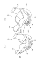
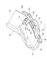
図1(a)は実施の形態に係るチャイルドシートの斜視図であり、着座部を後退させた状態を示す。図1(b)は図1(a)のチャイルドシートの着座部を前進させた状態を示す斜視図である。図2(a)は図1(b)の状態から着座部を180°回転させたときの斜視図、図2(b)は図2(a)の状態で着座部をリクライニングさせたときの斜視図、図3は着座部、回転板及び基台の分解斜視図、図4は基台と回転板との係合関係を示す分解斜視図、図5(a)は基台と回転板との係合関係を示す斜視図、図5(b)は図5(a)のB−B線に沿う断面図である。図6は回転板を進退させた状態の断面図、図7は回転板を前進させて180°回転させた状態の断面図、図8は図7と同じ状態を下方から見上げた断面図、図9はチャイルドシートの全体断面斜視図、図10はチャイルドシートの全体縦断面図、図11は基台の起立部の上部の断面図である。
【0014】
このチャイルドシート10は、車両のシートベルト装置のウェビング(ショルダーベルト12及びラップベルト14)によって車両の座席(図示略)に固定されるものであり、基台20と、回転板40と、着座部80とを備えている。
【0015】
図1〜4に明瞭に示される通り、基台20は、車両の座席のシートクッション上に載置される底部22と、該底部22の後部から立ち上がり車両の座席のシートバッグに沿って配置される起立部24とを備えてなる。この起立部24の前面にはウェビングが掛止される掛止部26a,26b,26c,26d,26eが設けられている。掛止部26a,26bは起立部24の上部の左右両サイドに配置され、掛止部26cは起立部24の中間高さのセンター付近に配置され、掛止部26d,26eは起立部24の下部の左右両サイドに配置されている。ショルダーベルト12は、上部の掛止部26a,26bの一方と、中間高さの掛止部26cとに掛止される。ラップベルト14は下部の掛止部26d,26eの双方に掛止される。
【0016】
底部22の上面には、回転板40が係合する凹部28が設けられている。この凹部28は、図4に明瞭に示される通り、前方側が略円形部分28aとなっている。凹部28の後方側は、1対の平行部を有し且つ後辺が略円弧形に膨出した略長方形部分28bとなっており、平面視形状が鍵孔形状となっている。この凹部28の周壁には張り出し部30が周設され、凹部28の底面と張り出し部30との間の凹陥部分が後述する回転板40の下板42のフランジ部50aが入り込むガイド部32となっている。
【0017】
この基台20の底部22の前部上面にはロックハンドル36が設けられている。底部22の後部上面のうち凹部28の近傍には回転板40の後述する上板44の押え部38が設けられている。凹部28内には、回転板40の回転のためのガイドローラ39が設けられている。
【0018】
回転板40は、図3〜8に明瞭に示される通り、下板42と、上板44と、ロック解除レバー46とを有する。下板42は、図4,5の通り、円形プレート50と、該円形プレート50の上面に突設された凸部としての囲壁52と、該ロック解除レバー46の進退を案内するための1対のガイド壁54と、ロックピン56の上下動を案内する半割円筒状のピンガイド部58とを有する。
【0019】
該囲壁52は円形プレート50の周縁から所定距離離隔しており、円形プレート50の周縁部はフランジ部50aとなっている。このフランジ部50aが前記ガイド部32に係合する。
【0020】
囲壁52は、円形プレート50と同心円状の円弧部52a、52cと、これらの円弧部52a、52cを結ぶ1対の弦状の平行部52bとを有した有弦円形状のものとなっている。この円弧部52a、52cを結ぶ方向の囲壁の長径(外径)は、前記凹部28の略円形部分28aの内径よりもごくわずか小さくなっている。囲壁52は、従ってその円弧部52a、52cが略円形部分28aの内周面に沿って摺動回転可能となっている。
【0021】
平行部52b,52b間の長さ(外面同士の間の長さ)は前記凹部28の略長方形部分28bの幅員よりもごくわずか小さくなっており、この平行部52bは略長方形部分28bに沿ってチャイルドシートの前後方向に摺動可能となっている。
【0022】
なお、円弧部52aの円弧方向の両端部は平行部52bの外方に突出しており、円弧部52aの弦方向の長さはこの略長方形部分28bの幅員よりも大きく、従って、円弧部52aは略長方形部分28b内に侵入不能となっている。即ち、後述の図7,8のように回転板40を図5の状態から前進させ且つ180°回転させた状態にあっては、円弧部52aが略長方形部分28b内に侵入しないので、回転板40が後退しない。
【0023】
ロック解除レバー46は、ガイド壁54,54間に配置され、ガイド壁54,54に沿って摺動可能な直棒部46aと、該直棒部46aに連っており、上方に起立した突片状のハンドル部46bとを有している。この直棒部46aの後部は囲壁52の円弧部52cを乗り越えて囲壁52の外方にまで延在しており、ハンドル部46bは囲壁52の外側に配置されている。図6〜8に示すように、このハンドル部46bは上板44に設けられた開口60内に配置されている。
【0024】
図5〜10に明示の通り、直棒部46aの前端側には、前方ほど上位となるように斜めに延在するピン保持孔62が設けられており、このピン保持孔62にロックピン56が挿通されている。このロックピン56の双方の端部56aは、下方に垂下しており、前記ピンガイド部58内に配置されている。このピンガイド部58が上下方向に延在する半割円筒状であり、ロックピン56の端部56aは上下方向にのみ移動可能である。従って、ロック解除レバー46を円形プレート50上をガイド壁54に沿ってスライドさせることにより、ロックピン56が上下動する。
【0025】
下板42の円形プレート50には、このロックピン56の端部56aの下端が入り込んだ孔64が設けられている。前記基台20の底部22には、図8の通り、この回転板40が前進し180°回転したときには該ロックピン56の端部56aの下端が入り込むロック孔66が設けられている。
【0026】
上板44は、この下板42に重ね合わされ、ボルト又はビスあるいは接着剤(いずれも図示略)によって該下板42に固定され、回転板40が構成される。この回転板40は、基台20の底部22の上面に沿って前後進及び回転可能である。
【0027】
この上板44の上面には、着座部80を支承する凸条70が平行に2条設けられている。この凸条70は、着座部80がリクライニングしうるように上面がチャイルドシート10の前後方向に凹曲している。この上板44には、着座部80に設けられたステー82(図2,8)が嵌合するステー嵌合部74が前記開口60(図6)の後方の上面に突設されている。
【0028】
上板44の下面側には、円形状のガイドレール72が上板44と一体に設けられている。このガイドレール72は、上板44の前縁側に配置されている。このガイドレール72の外周縁に沿って段部72aが延設されており、上板44を前進させて180°回転させると、図7の如くこの段部72aが押え部38と係合し、上板44が該押え部38を介して底部22に係止される。
【0029】
前記ロックハンドル36は、着座部80が前方を向いているときに回転板40及び着座部80をロックするためのものである。このロックハンドル36からは第1のリンク90が後方に延設され、該第1のリンク90の後端にスライダ92が連結されている。このスライダ92には、前方ほど上位となる斜めのピン保持孔94が設けられ、このピン保持孔94にピン96が挿通されている。このピン96は双方の端部96aが上方に立ち上げられており、この端部96aの上端が底部22の底面に設けられたピン挿通孔(図示略)に挿通されている。円形プレート50にはこのピン端部96aの上端が入り込む孔(図示略)が設けられており、ピン端部96aが上昇して円形プレート50の該孔に入り込むことにより円形プレート50の回転が阻止される。
【0030】
このスライダ92には後方延長部92aが設けられており、図8〜10の通り、この後方延長部92aは底部22の段部98の開口100に挿通されている。この後方延長部92aの後端部に第2のリンク102の先端102a(図8)が係合している。
【0031】
この第2のリンク102の後端は、基台20に支軸104aによって回動自在に支持されたリンクアーム104に連結されている。このリンクアーム104には第3のリンク106の下端が連結されている。
【0032】
該第3のリンク106の上端は起立部24の上部のスライドプレート108に接続されている。このスライドプレート108は、図11の通り、該起立部24内に設けられた案内板110に沿って上下動自在とされている。この案内板には縦長のスロット112と横長のスロット114とが設けられており、第3のリンク106の上端は該縦長のスロット112に挿通されている。
【0033】
スライドプレート108には斜めのピン保持孔116が設けられており、ロックピン120の後端部120aが該ピン保持孔116に係合している。このロックピンの後端部120aは、案内板110の横長のスロット114にも係合している。
【0034】
ロックピン120の先端部120bは、図3の通り、起立部24の上部側面の孔124に挿通されている。ロックピン120は、このように後端部120aが横長スロット114に係合し、先端部120bが孔124に係合しているので、上下方向に移動不能で水平方向にのみ移動可能である。そして、スライドプレート108が引き下げられると、ロックピン120の先端部120bが後退し、スライドプレート108が押し上げられると該先端部120bが孔124から突出する。着座部80の背面には、この突出したロックピン先端部120bが入り込む孔126(図2(a))が設けられている。
【0035】
このように構成されたチャイルドシート10の使用方法について次に説明する。
【0036】
このチャイルドシート10を自動車の座席に固定するには、まず、ロックハンドル36を正方向に回してロックピン96,120によるロックを解除し、図1(b)のように着座部80を前進させるか、又は図2(a),(b)のように着座部80を前進させてから回す。そして、図3の如く、ショルダーベルト12を掛止部26a,26bの一方と掛止部26cとに掛止し、ラップベルト14を掛止部26d,26eに掛け、チャイルドシート10を座席に固定する。
【0037】
なお、ロックハンドル36を正方向に回すと、第1のリンク90が前進(図9の左方向に移動)し、スライダ92が前進し、ロックピン96が引き下げられ、その端部上端が下板42の円形プレート50の孔から抜け出る。これにより、回転板40が前進可能となる。
【0038】
スライダ92が前進すると、第2のリンク102も前進し、リンクアーム104を介して第3のリンク106が引き下げられ、スライドプレート108も引き下げられる。これによりロックピン120が後退し、着座部80のロックが解除される。
【0039】
なお、回転板40が前進する場合、囲壁52の平行部52bが底部22の略長方形部分28bに沿って移動する。囲壁52の全体が略円形部分28a内に入ると、下板42は該略円形部分28a内で回転可能となる。下板42が略円形部分28a内で回転する場合、円弧部52a,52cが該略円形部分28aの内周に沿って回転する。
【0040】
チャイルドシート10を座席に固定した後、正面を向いた着座部80を後退させ、着座部80をロックすることにより、チャイルドシート10を正面向き姿勢にて使用することが可能となる。
【0041】
着座部80をロックするには、ロックハンドル36をアンロック時とは逆方向に回転させる。これにより第1のリンク90及びスライダ92が後退(図9の右方向に移動)し、ロックピン96が上方に移動し、その両端部96aが下板42の孔に入り込み、下板42がロックされる。これにより、下板42は前進及び回転が不可能となる。
【0042】
スライダ92が後退すると、第2のリンク102も後退し、リンクアーム104を介して第3のリンク106が押し上げられる。これにより、スライドプレート108も押し上げられロックピン120の端部120bが孔124から突出して着座部80の孔126に入り込み、着座部80がロックされる。
【0043】
着座部80を後向きにして使用するには、ロックハンドル36を正方向に回してロックピン96,120によるロックを解除した後、着座部80を回転板40と共に前進させる。
【0044】
回転板40の下板42の囲壁52が略円形部分28a内に入り込んだ後、着座部80を180°回転させる。そうすると、図2(a)及び図7,8の如く、ロックピン56の両端部56aが底部22の孔66に入り込み、回転板40が回転不能なロック状態となり、着座部80が後向き姿勢を維持するようになる。
【0045】
この状態でリクライニングさせたときには、図2(b)及び図8の如く、ステー82の下部をステー嵌合部74に嵌合させる。
【0046】
着座部80を正面向きに戻すには、図2(a),(b)及び図7,8の状態においてロック解除レバー46のハンドル46bを図8の左方に引く。そうすると、斜めのピン保持孔62に挿通されたロックピン56が引き上げられ、両端部56aが孔66から引き抜かれ、回転板40が回転可能となる。そこで、回転板40と共に着座部80を180°回して正面向きの姿勢に戻す。
【0047】
このようにチャイルドシート10によると、着座部80を前進させたり、あるいはさらに回転させて起立部24から離反させた状態としておいて、ウェビング(ショルダーベルト12、ラップベルト14)を掛止部26a〜26eに掛けることができるため、ウェビングをきわめて簡単に掛止部26a〜26eに掛けることができる。また、着座部80を回転させるときには、着座部80を若干前進させてから回転させるので、着座部80と起立部24とが干渉することがなく、着座部80を回し易い。
【0048】
【発明の効果】
以上の通り、本発明によると、チャイルドシートをウェビングで固定する作業及びチャイルドシートからウェビングを取り外す作業が簡単になる。また、着座部を簡易に回転させることも可能となる。
【図面の簡単な説明】
【図1】(a)は本発明の実施の形態に係るチャイルドシートの斜視図であり、着座部を後退させた状態を示す。(b)は(a)のチャイルドシートの着座部を前進させた状態を示す斜視図である。
【図2】(a)は図1(b)の状態から着座部を180°回転させたときの斜視図、(b)は(a)の状態で着座部をリクライニングさせたときの斜視図である。
【図3】着座部、回転板及び基台の分解斜視図である。
【図4】基台と回転板との係合関係を示す分解斜視図である。
【図5】(a)は基台と回転板との係合関係を示す斜視図、(b)は(a)のB−B線に沿う断面図である。
【図6】回転板を進退させた状態の断面図である。
【図7】回転板を前進させて180°回転させた状態の断面図である。
【図8】図7と同じ状態を下方から見上げた断面図である。
【図9】チャイルドシートの全体断面斜視図である。
【図10】チャイルドシートの全体縦断面図である。
【図11】基台の起立部の上部の断面図である。
【符号の説明】
10 チャイルドシート
20 基台
22 底部
24 起立部
26a〜26e 掛止部
28 凹部
28a 略円形部分
28b 略長方形部分
30 張り出し部
32 ガイド部
36 ロックハンドル
38 押え部
39 ガイドローラ
40 回転板
42 下板
44 上板
46 ロック解除レバー
46a 直棒部
46b ハンドル部
50 円形プレート
52 囲壁(凸部)
52a,52c 円弧部
52b 平行部
54 ガイド壁
56 ロックピン
62 ピン保持孔
66 孔
70 凸条部
80 着座部
82 ステー
90 第1のリンク
92 スライダ
102 第2のリンク
104 リンクアーム
106 第3のリンク
108 スライドプレート
120 ロックピン
124 孔[0001]
BACKGROUND OF THE INVENTION
The present invention relates to a child seat disposed in a vehicle seat, and more particularly to a child seat in which a seating portion is rotatable or movable back and forth.
[0002]
[Prior art]
There is a child seat for allowing an infant to sit, with a seating portion that is rotatable. (Unexamined-Japanese-Patent No. 1-113007, Unexamined-Japanese-Patent No. 6-329992). If the seating portion is made rotatable as described above, it becomes easy to perform an operation of seating or lowering the infant on the child seat by setting the seating portion sideways as described in JP-A-6-329992. Further, as described in JP-A-1-113007, it is possible to direct the seating portion not only to the front of the vehicle but also to the rear of the vehicle.
[0003]
[Problems to be solved by the invention]
An object of the present invention is to provide a child seat in which a seating portion can be easily rotated to change the orientation of the seating portion. It is another object of the present invention to provide a child seat that can be easily fixed to a vehicle seat.
[0004]
[Means for Solving the Problems]
Child seat of the present invention (Claim 1) includes a base fixed to a vehicle seat, in the child seat and a rotatable seat to the base board, the base has, on a seat cushion of the vehicle seat A child seat that has a bottom portion to be disposed and an upright portion along the seat back, and the seating portion is slidable forward so as to be separated from the upright portion, and rotates to the bottom portion of the base A plate is disposed so as to be slidable in the front-rear direction of the base, and the seating portion is supported by the rotary plate, and one of the base and the rotary plate has a circular portion on the front side and a substantially square portion on the rear side. A recess is provided, and the other of the base and the rotary plate is engaged with the recess so as to be slidable in the front-rear direction, and can be rotated when in the circular portion and within the substantially rectangular portion. Sometimes it can't rotate It is characterized in that the convex portion of a non-circular is provided.
[0005]
In such a child seat, when the seating portion is slid forward, the seating portion can freely rotate without hitting the standing portion of the base. Further, when the seating portion is slid forward, there is a gap between the seating portion and the upright portion, so that the child seat can be fixed to the vehicle seat through the webbing and the webbing can be removed.
[0006]
By providing a webbing latching portion on the front surface of the upright portion, the upright portion can be attached to the vehicle very firmly by webbing. In the present invention, to place the rotating plate slide and rotatably to the bottom of the base, by supporting the seat on the rotary plate, and a sliding and rotatable seating unit.
[0007]
In the present invention, a recess having a circular portion on the front side and a substantially rectangular portion on the rear side is provided on one of the base and the rotating plate, and the other of the base and the rotating plate can slide in the front-rear direction. When the rotating plate is positioned forward, a non-circular convex portion is provided that is rotatable when in the circular portion and is rotatable when in the substantially rectangular portion. Can only be rotated. In this case, the rotating plate may be configured to be slidable in the front-rear direction only when the seating portion is directed forward.
[0008]
This convex part is formed as a surrounding wall, for example.
[0009]
In the present invention, the seating portion may be reclining with respect to the rotating plate. When the seating portion is positioned forward, the seating portion can be reclined deeply .
[0010]
In the present invention, first locking means may be provided for preventing forward movement of the rotating plate when the rotating plate is in the retracted position. Further, there may be provided second locking means for preventing rotation and rearward movement of the rotating plate when the rotating plate is in the forward position and the seating portion is directed rearward .
[0011]
In the present invention, the standing portion is provided with a latching portion to which the webbing of the seat belt device of the vehicle is latched, the webbing has a lap belt and a shoulder belt, It is preferable that a latching portion on which the lap belt is latched and a latching portion on which the shoulder belt is latched are provided separately.
[0012]
DETAILED DESCRIPTION OF THE INVENTION
Hereinafter, embodiments will be described with reference to FIGS.
[0013]
Fig.1 (a) is a perspective view of the child seat which concerns on embodiment, and shows the state which retracted the seating part. FIG.1 (b) is a perspective view which shows the state which advanced the seating part of the child seat of Fig.1 (a). 2A is a perspective view when the seating portion is rotated 180 ° from the state of FIG. 1B, and FIG. 2B is a perspective view when the seating portion is reclined in the state of FIG. 2A. 3 is an exploded perspective view of the seating portion, the rotating plate and the base, FIG. 4 is an exploded perspective view showing an engagement relationship between the base and the rotating plate, and FIG. 5A is a view of the base and the rotating plate. FIG. 5B is a cross-sectional view taken along the line BB in FIG. 5A. 6 is a cross-sectional view of the state in which the rotary plate is advanced and retracted, FIG. 7 is a cross-sectional view of the state in which the rotary plate is advanced and rotated 180 °, and FIG. 8 is a cross-sectional view of the same state as FIG. 9 is an overall cross-sectional perspective view of the child seat, FIG. 10 is an overall longitudinal cross-sectional view of the child seat, and FIG. 11 is a cross-sectional view of the upper portion of the upright portion of the base.
[0014]
The
[0015]
As clearly shown in FIGS. 1 to 4, the
[0016]
On the upper surface of the
[0017]
A lock handle 36 is provided on the upper surface of the front portion of the
[0018]
The
[0019]
The surrounding
[0020]
The surrounding
[0021]
The length between the
[0022]
Both ends of the
[0023]
The
[0024]
As clearly shown in FIGS. 5 to 10, on the front end side of the
[0025]
The
[0026]
The
[0027]
On the upper surface of the
[0028]
A
[0029]
The lock handle 36 is for locking the
[0030]
The
[0031]
The rear end of the
[0032]
The upper end of the
[0033]
The
[0034]
The
[0035]
Next, a method of using the
[0036]
In order to fix the
[0037]
When the lock handle 36 is rotated in the forward direction, the
[0038]
When the
[0039]
When the
[0040]
After the
[0041]
In order to lock the
[0042]
When the
[0043]
In order to use the
[0044]
After the surrounding
[0045]
When reclining in this state, the lower portion of the
[0046]
To return the
[0047]
As described above, according to the
[0048]
【The invention's effect】
As described above, according to the present invention, the operation of fixing the child seat with the webbing and the operation of removing the webbing from the child seat are simplified. In addition, the seating part can be simply rotated.
[Brief description of the drawings]
FIG. 1A is a perspective view of a child seat according to an embodiment of the present invention, and shows a state in which a seating portion is retracted. (B) is a perspective view which shows the state which advanced the seating part of the child seat of (a).
2A is a perspective view when the seating portion is rotated 180 ° from the state of FIG. 1B, and FIG. 2B is a perspective view when the seating portion is reclined in the state of FIG. is there.
FIG. 3 is an exploded perspective view of a seating portion, a rotating plate, and a base.
FIG. 4 is an exploded perspective view showing an engagement relationship between a base and a rotating plate.
5A is a perspective view showing an engagement relationship between a base and a rotating plate, and FIG. 5B is a cross-sectional view taken along line BB in FIG. 5A.
FIG. 6 is a cross-sectional view of a state in which a rotating plate is advanced and retracted.
FIG. 7 is a cross-sectional view of a state in which a rotating plate is advanced and rotated 180 °.
FIG. 8 is a cross-sectional view of the same state as FIG. 7 as viewed from below.
FIG. 9 is an overall cross-sectional perspective view of the child seat.
FIG. 10 is an overall longitudinal sectional view of a child seat.
FIG. 11 is a cross-sectional view of the upper part of the upright portion of the base.
[Explanation of symbols]
DESCRIPTION OF
52a,
Claims (7)
該基台は、車両座席のシートクッション上に配置される底部と、シートバックに沿う起立部とを有しており、該着座部は、該起立部から離反するように前方へスライド可能であるチャイルドシートであって、
前記基台の底部に回転板が基台の前後方向にスライド可能に配置されており、該回転板に前記着座部が支持されており、
前記基台と回転板の一方に、前方側が円形部分であり後方側が略方形部分である凹部が設けられており、
基台と回転板との他方に、該凹部に前後方向スライド可能に係合しており、該円形部分内にあるときには回転可能であり該略方形部分内にあるときには回転不能である非円形の凸部が設けられていることを特徴とするチャイルドシート。In a child seat having a base fixed to a seat of a vehicle and a seating portion rotatable relative to the base ,
The base has a bottom portion disposed on the seat cushion of the vehicle seat has a standing part along the seat back, the seating unit is slidable forwardly so away from the standing Tatsubu A child seat,
A rotating plate is disposed at the bottom of the base so as to be slidable in the front-rear direction of the base, and the seating portion is supported by the rotating plate,
One of the base and the rotating plate is provided with a concave portion whose front side is a circular portion and whose rear side is a substantially square portion,
A non-circular shape that is slidably engaged with the concave portion on the other side of the base and the rotating plate, can rotate when in the circular portion, and cannot rotate when in the substantially rectangular portion. A child seat characterized in that a convex portion is provided .
Priority Applications (1)
| Application Number | Priority Date | Filing Date | Title |
|---|---|---|---|
| JP21899399A JP3620358B2 (en) | 1998-08-05 | 1999-08-02 | child seat |
Applications Claiming Priority (3)
| Application Number | Priority Date | Filing Date | Title |
|---|---|---|---|
| JP22183998 | 1998-08-05 | ||
| JP10-221839 | 1998-08-05 | ||
| JP21899399A JP3620358B2 (en) | 1998-08-05 | 1999-08-02 | child seat |
Related Child Applications (1)
| Application Number | Title | Priority Date | Filing Date |
|---|---|---|---|
| JP2003288974A Division JP4206859B2 (en) | 1998-08-05 | 2003-08-07 | child seat |
Publications (2)
| Publication Number | Publication Date |
|---|---|
| JP2000108739A JP2000108739A (en) | 2000-04-18 |
| JP3620358B2 true JP3620358B2 (en) | 2005-02-16 |
Family
ID=26522863
Family Applications (1)
| Application Number | Title | Priority Date | Filing Date |
|---|---|---|---|
| JP21899399A Expired - Fee Related JP3620358B2 (en) | 1998-08-05 | 1999-08-02 | child seat |
Country Status (1)
| Country | Link |
|---|---|
| JP (1) | JP3620358B2 (en) |
Families Citing this family (17)
| Publication number | Priority date | Publication date | Assignee | Title |
|---|---|---|---|---|
| JP4434394B2 (en) | 1999-12-21 | 2010-03-17 | コンビ株式会社 | Swivel child seat |
| AUPQ688200A0 (en) * | 2000-04-14 | 2000-05-11 | Britax Child-Care Products Pty Ltd | A tether strap for a rotating safety seat |
| AUPQ688500A0 (en) * | 2000-04-14 | 2000-05-11 | Britax Child-Care Products Pty Ltd | A tether strap that allows rotation of a safety seat about a vertical axis |
| FR2812253B1 (en) * | 2000-07-26 | 2004-03-05 | Renolux France Ind | AUTOMOTIVE SAFETY DEVICE FOR A CHILD WITH AN INDEPENDENT BASE |
| US6746080B2 (en) * | 2001-04-05 | 2004-06-08 | Combi Corporation | Child car seat |
| JP4588242B2 (en) * | 2001-04-05 | 2010-11-24 | コンビ株式会社 | child seat |
| JP4588241B2 (en) * | 2001-04-05 | 2010-11-24 | コンビ株式会社 | child seat |
| CA2353111A1 (en) | 2001-07-13 | 2003-01-13 | Aprica Kassai Kabushikikaisha | Vehicular child safety seat |
| FR2828846B1 (en) * | 2001-08-24 | 2004-02-13 | Renault | HORIZONTAL SWIVEL SEAT OF AT LEAST ONE HALF-TURN |
| AU2002952108A0 (en) * | 2002-10-14 | 2002-10-31 | Suzanne Wendy Belramoul | A child restraint |
| GB2397219A (en) * | 2003-01-15 | 2004-07-21 | Jacky Norton | Swivel car seat |
| AU2016256730B2 (en) * | 2010-02-01 | 2019-01-31 | Hbg Ip Holding Pty Ltd | A Child Restraint for a Vehicle |
| US10322651B2 (en) * | 2016-06-14 | 2019-06-18 | Wonderland Switzerland Ag | Child safety seat |
| US10688892B2 (en) * | 2017-03-17 | 2020-06-23 | Wonderland Switzerland Ag | Child safety seat |
| KR102122866B1 (en) * | 2018-06-04 | 2020-06-15 | 이재원 | a baby car seat which is easy to control the angle |
| KR102216343B1 (en) * | 2018-06-05 | 2021-02-17 | 주식회사 순성산업 | device for isofix which is able to adjust an angle |
| CN109606214A (en) * | 2018-10-29 | 2019-04-12 | 宁波后乐婴童用品有限公司 | A kind of child safety seat |
-
1999
- 1999-08-02 JP JP21899399A patent/JP3620358B2/en not_active Expired - Fee Related
Also Published As
| Publication number | Publication date |
|---|---|
| JP2000108739A (en) | 2000-04-18 |
Similar Documents
| Publication | Publication Date | Title |
|---|---|---|
| JP3620358B2 (en) | child seat | |
| JP3890772B2 (en) | child seat | |
| JP3735935B2 (en) | Headrest device | |
| US8573674B2 (en) | Vehicle seat | |
| JPH0281738A (en) | Seat device for vehicle | |
| JP2016532601A (en) | Child safety seat | |
| JP2007091200A (en) | Car seat for child | |
| JP4206859B2 (en) | child seat | |
| JP4946039B2 (en) | child seat | |
| JP2000177434A (en) | Instrument panel | |
| JP2000006694A (en) | Slide lock mechanism of seat slide device | |
| JPH0115419B2 (en) | ||
| JP3062653B2 (en) | child seat | |
| JP4439647B2 (en) | Child seat fixing device | |
| JP2004082823A (en) | Vehicle seat | |
| JP3901905B2 (en) | Child seat fixing device | |
| JP4000557B2 (en) | Vehicle seat to which a child seat can be attached | |
| JP3900574B2 (en) | Seat slide device | |
| JP3946926B2 (en) | Child seat fixing device | |
| JP2583091Y2 (en) | Turning sheet | |
| JP3050511B2 (en) | Vehicle seat slide device | |
| JPS6340047Y2 (en) | ||
| JP2005028943A (en) | Child seat | |
| JP5365461B2 (en) | Reclining device for vehicle seat | |
| JP2002087123A (en) | Child seat |
Legal Events
| Date | Code | Title | Description |
|---|---|---|---|
| TRDD | Decision of grant or rejection written | ||
| A01 | Written decision to grant a patent or to grant a registration (utility model) |
Free format text: JAPANESE INTERMEDIATE CODE: A01 Effective date: 20041026 |
|
| A61 | First payment of annual fees (during grant procedure) |
Free format text: JAPANESE INTERMEDIATE CODE: A61 Effective date: 20041108 |
|
| R150 | Certificate of patent or registration of utility model |
Free format text: JAPANESE INTERMEDIATE CODE: R150 |
|
| S111 | Request for change of ownership or part of ownership |
Free format text: JAPANESE INTERMEDIATE CODE: R313111 |
|
| R350 | Written notification of registration of transfer |
Free format text: JAPANESE INTERMEDIATE CODE: R350 |
|
| FPAY | Renewal fee payment (event date is renewal date of database) |
Free format text: PAYMENT UNTIL: 20081126 Year of fee payment: 4 |
|
| FPAY | Renewal fee payment (event date is renewal date of database) |
Free format text: PAYMENT UNTIL: 20081126 Year of fee payment: 4 |
|
| FPAY | Renewal fee payment (event date is renewal date of database) |
Free format text: PAYMENT UNTIL: 20091126 Year of fee payment: 5 |
|
| FPAY | Renewal fee payment (event date is renewal date of database) |
Free format text: PAYMENT UNTIL: 20091126 Year of fee payment: 5 |
|
| S531 | Written request for registration of change of domicile |
Free format text: JAPANESE INTERMEDIATE CODE: R313531 |
|
| FPAY | Renewal fee payment (event date is renewal date of database) |
Free format text: PAYMENT UNTIL: 20091126 Year of fee payment: 5 |
|
| R350 | Written notification of registration of transfer |
Free format text: JAPANESE INTERMEDIATE CODE: R350 |
|
| FPAY | Renewal fee payment (event date is renewal date of database) |
Free format text: PAYMENT UNTIL: 20091126 Year of fee payment: 5 |
|
| FPAY | Renewal fee payment (event date is renewal date of database) |
Free format text: PAYMENT UNTIL: 20101126 Year of fee payment: 6 |
|
| FPAY | Renewal fee payment (event date is renewal date of database) |
Free format text: PAYMENT UNTIL: 20111126 Year of fee payment: 7 |
|
| FPAY | Renewal fee payment (event date is renewal date of database) |
Free format text: PAYMENT UNTIL: 20121126 Year of fee payment: 8 |
|
| FPAY | Renewal fee payment (event date is renewal date of database) |
Free format text: PAYMENT UNTIL: 20121126 Year of fee payment: 8 |
|
| FPAY | Renewal fee payment (event date is renewal date of database) |
Free format text: PAYMENT UNTIL: 20131126 Year of fee payment: 9 |
|
| R250 | Receipt of annual fees |
Free format text: JAPANESE INTERMEDIATE CODE: R250 |
|
| LAPS | Cancellation because of no payment of annual fees |