JP3615979B2 - Semiconductor device and manufacturing method thereof - Google Patents
Semiconductor device and manufacturing method thereof Download PDFInfo
- Publication number
- JP3615979B2 JP3615979B2 JP2000013895A JP2000013895A JP3615979B2 JP 3615979 B2 JP3615979 B2 JP 3615979B2 JP 2000013895 A JP2000013895 A JP 2000013895A JP 2000013895 A JP2000013895 A JP 2000013895A JP 3615979 B2 JP3615979 B2 JP 3615979B2
- Authority
- JP
- Japan
- Prior art keywords
- film
- insulating film
- silicon
- atoms
- oxygen
- Prior art date
- Legal status (The legal status is an assumption and is not a legal conclusion. Google has not performed a legal analysis and makes no representation as to the accuracy of the status listed.)
- Expired - Fee Related
Links
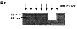
- 239000004065 semiconductor Substances 0.000 title claims description 34
- 238000004519 manufacturing process Methods 0.000 title claims description 19
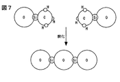
- 238000000034 method Methods 0.000 claims description 56
- 239000011229 interlayer Substances 0.000 claims description 39
- XUIMIQQOPSSXEZ-UHFFFAOYSA-N Silicon Chemical compound [Si] XUIMIQQOPSSXEZ-UHFFFAOYSA-N 0.000 claims description 38
- QVGXLLKOCUKJST-UHFFFAOYSA-N atomic oxygen Chemical compound [O] QVGXLLKOCUKJST-UHFFFAOYSA-N 0.000 claims description 35
- 239000001301 oxygen Substances 0.000 claims description 35
- 229910052760 oxygen Inorganic materials 0.000 claims description 35
- 239000010410 layer Substances 0.000 claims description 30
- 239000007789 gas Substances 0.000 claims description 25
- 229910052751 metal Inorganic materials 0.000 claims description 23
- 239000002184 metal Substances 0.000 claims description 23
- OKTJSMMVPCPJKN-UHFFFAOYSA-N Carbon Chemical compound [C] OKTJSMMVPCPJKN-UHFFFAOYSA-N 0.000 claims description 22
- VYPSYNLAJGMNEJ-UHFFFAOYSA-N Silicium dioxide Chemical compound O=[Si]=O VYPSYNLAJGMNEJ-UHFFFAOYSA-N 0.000 claims description 22
- 229910052799 carbon Inorganic materials 0.000 claims description 22
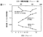
- 229910052814 silicon oxide Inorganic materials 0.000 claims description 22
- IJGRMHOSHXDMSA-UHFFFAOYSA-N Atomic nitrogen Chemical compound N#N IJGRMHOSHXDMSA-UHFFFAOYSA-N 0.000 claims description 18
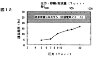
- 229910021419 crystalline silicon Inorganic materials 0.000 claims description 18
- 125000004432 carbon atom Chemical group C* 0.000 claims description 13
- 125000004430 oxygen atom Chemical group O* 0.000 claims description 13
- 238000006243 chemical reaction Methods 0.000 claims description 12
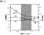
- 230000001590 oxidative effect Effects 0.000 claims description 11
- 229910052757 nitrogen Inorganic materials 0.000 claims description 9
- QGZKDVFQNNGYKY-UHFFFAOYSA-N Ammonia Chemical compound N QGZKDVFQNNGYKY-UHFFFAOYSA-N 0.000 claims description 8
- 238000005229 chemical vapour deposition Methods 0.000 claims description 8
- 230000003647 oxidation Effects 0.000 claims description 8
- 238000007254 oxidation reaction Methods 0.000 claims description 8
- 238000009832 plasma treatment Methods 0.000 claims description 8
- 238000005498 polishing Methods 0.000 claims description 7
- 239000000126 substance Substances 0.000 claims description 6
- CPUDPFPXCZDNGI-UHFFFAOYSA-N triethoxy(methyl)silane Chemical compound CCO[Si](C)(OCC)OCC CPUDPFPXCZDNGI-UHFFFAOYSA-N 0.000 claims description 6
- 238000001312 dry etching Methods 0.000 claims description 5
- 239000011261 inert gas Substances 0.000 claims description 5
- 229910021529 ammonia Inorganic materials 0.000 claims description 4
- 239000001257 hydrogen Substances 0.000 claims description 4
- 229910052739 hydrogen Inorganic materials 0.000 claims description 4
- 125000004429 atom Chemical group 0.000 claims description 3
- 125000004435 hydrogen atom Chemical class [H]* 0.000 claims description 3
- 239000000203 mixture Substances 0.000 claims description 3
- 239000001307 helium Substances 0.000 claims description 2
- 229910052734 helium Inorganic materials 0.000 claims description 2
- SWQJXJOGLNCZEY-UHFFFAOYSA-N helium atom Chemical compound [He] SWQJXJOGLNCZEY-UHFFFAOYSA-N 0.000 claims description 2
- BFXIKLCIZHOAAZ-UHFFFAOYSA-N methyltrimethoxysilane Chemical compound CO[Si](C)(OC)OC BFXIKLCIZHOAAZ-UHFFFAOYSA-N 0.000 claims description 2
- 239000010703 silicon Substances 0.000 claims 15
- 229910052710 silicon Inorganic materials 0.000 claims 15
- XKRFYHLGVUSROY-UHFFFAOYSA-N Argon Chemical compound [Ar] XKRFYHLGVUSROY-UHFFFAOYSA-N 0.000 claims 2
- 239000002356 single layer Substances 0.000 claims 2
- 229910002808 Si–O–Si Inorganic materials 0.000 claims 1
- 229910052786 argon Inorganic materials 0.000 claims 1
- ZZRGHKUNLAYDTC-UHFFFAOYSA-N ethoxy(methyl)silane Chemical compound CCO[SiH2]C ZZRGHKUNLAYDTC-UHFFFAOYSA-N 0.000 claims 1
- XPDGHGYGTJOTBC-UHFFFAOYSA-N methoxy(methyl)silicon Chemical compound CO[Si]C XPDGHGYGTJOTBC-UHFFFAOYSA-N 0.000 claims 1
- RYGMFSIKBFXOCR-UHFFFAOYSA-N Copper Chemical compound [Cu] RYGMFSIKBFXOCR-UHFFFAOYSA-N 0.000 description 33
- 229910052802 copper Inorganic materials 0.000 description 33
- 239000010949 copper Substances 0.000 description 33
- 230000008569 process Effects 0.000 description 32
- 238000010586 diagram Methods 0.000 description 31
- NRTOMJZYCJJWKI-UHFFFAOYSA-N Titanium nitride Chemical compound [Ti]#N NRTOMJZYCJJWKI-UHFFFAOYSA-N 0.000 description 25
- 206010040844 Skin exfoliation Diseases 0.000 description 17
- 230000001681 protective effect Effects 0.000 description 16
- 229910052581 Si3N4 Inorganic materials 0.000 description 13
- KPUWHANPEXNPJT-UHFFFAOYSA-N disiloxane Chemical class [SiH3]O[SiH3] KPUWHANPEXNPJT-UHFFFAOYSA-N 0.000 description 13
- HQVNEWCFYHHQES-UHFFFAOYSA-N silicon nitride Chemical compound N12[Si]34N5[Si]62N3[Si]51N64 HQVNEWCFYHHQES-UHFFFAOYSA-N 0.000 description 13
- 125000005375 organosiloxane group Chemical group 0.000 description 12
- 238000005530 etching Methods 0.000 description 11
- 229920000620 organic polymer Polymers 0.000 description 10
- 238000001020 plasma etching Methods 0.000 description 9
- 238000005268 plasma chemical vapour deposition Methods 0.000 description 7
- 238000012545 processing Methods 0.000 description 7
- 238000004544 sputter deposition Methods 0.000 description 7
- 239000000758 substrate Substances 0.000 description 7
- 230000015572 biosynthetic process Effects 0.000 description 6
- 230000008859 change Effects 0.000 description 6
- 238000009713 electroplating Methods 0.000 description 6
- 239000007788 liquid Substances 0.000 description 6
- 229910000838 Al alloy Inorganic materials 0.000 description 4
- 238000007796 conventional method Methods 0.000 description 4
- 125000002496 methyl group Chemical group [H]C([H])([H])* 0.000 description 4
- 230000009467 reduction Effects 0.000 description 4
- MZLGASXMSKOWSE-UHFFFAOYSA-N tantalum nitride Chemical compound [Ta]#N MZLGASXMSKOWSE-UHFFFAOYSA-N 0.000 description 4
- PXGOKWXKJXAPGV-UHFFFAOYSA-N Fluorine Chemical compound FF PXGOKWXKJXAPGV-UHFFFAOYSA-N 0.000 description 3
- 238000001157 Fourier transform infrared spectrum Methods 0.000 description 3
- 230000004888 barrier function Effects 0.000 description 3
- 229910052731 fluorine Inorganic materials 0.000 description 3
- 239000011737 fluorine Substances 0.000 description 3
- 238000012360 testing method Methods 0.000 description 3
- WFKWXMTUELFFGS-UHFFFAOYSA-N tungsten Chemical compound [W] WFKWXMTUELFFGS-UHFFFAOYSA-N 0.000 description 3
- 229910052721 tungsten Inorganic materials 0.000 description 3
- 239000010937 tungsten Substances 0.000 description 3
- 238000005033 Fourier transform infrared spectroscopy Methods 0.000 description 2
- 239000011248 coating agent Substances 0.000 description 2
- 238000000576 coating method Methods 0.000 description 2
- 230000008602 contraction Effects 0.000 description 2
- 230000007423 decrease Effects 0.000 description 2
- 230000032798 delamination Effects 0.000 description 2
- 238000000572 ellipsometry Methods 0.000 description 2
- 239000011521 glass Substances 0.000 description 2
- 238000009413 insulation Methods 0.000 description 2
- 239000000463 material Substances 0.000 description 2
- 238000005259 measurement Methods 0.000 description 2
- 238000000206 photolithography Methods 0.000 description 2
- 239000012495 reaction gas Substances 0.000 description 2
- LFQSCWFLJHTTHZ-UHFFFAOYSA-N Ethanol Chemical compound CCO LFQSCWFLJHTTHZ-UHFFFAOYSA-N 0.000 description 1
- UFHFLCQGNIYNRP-UHFFFAOYSA-N Hydrogen Chemical compound [H][H] UFHFLCQGNIYNRP-UHFFFAOYSA-N 0.000 description 1
- BLRPTPMANUNPDV-UHFFFAOYSA-N Silane Chemical compound [SiH4] BLRPTPMANUNPDV-UHFFFAOYSA-N 0.000 description 1
- 229910008284 Si—F Inorganic materials 0.000 description 1
- 239000012790 adhesive layer Substances 0.000 description 1
- 238000004458 analytical method Methods 0.000 description 1
- 125000003118 aryl group Chemical group 0.000 description 1
- UMIVXZPTRXBADB-UHFFFAOYSA-N benzocyclobutene Chemical compound C1=CC=C2CCC2=C1 UMIVXZPTRXBADB-UHFFFAOYSA-N 0.000 description 1
- 239000012159 carrier gas Substances 0.000 description 1
- 239000007795 chemical reaction product Substances 0.000 description 1
- 229910003460 diamond Inorganic materials 0.000 description 1
- 239000010432 diamond Substances 0.000 description 1
- 230000009977 dual effect Effects 0.000 description 1
- 230000000694 effects Effects 0.000 description 1
- 238000005516 engineering process Methods 0.000 description 1
- 230000007717 exclusion Effects 0.000 description 1
- 230000007246 mechanism Effects 0.000 description 1
- 239000012528 membrane Substances 0.000 description 1
- 150000002739 metals Chemical class 0.000 description 1
- 125000000956 methoxy group Chemical group [H]C([H])([H])O* 0.000 description 1
- 230000003287 optical effect Effects 0.000 description 1
- 125000000962 organic group Chemical group 0.000 description 1
- 230000003071 parasitic effect Effects 0.000 description 1
- 239000002994 raw material Substances 0.000 description 1
- 239000011347 resin Substances 0.000 description 1
- 229920005989 resin Polymers 0.000 description 1
- 229910000077 silane Inorganic materials 0.000 description 1
- 238000004528 spin coating Methods 0.000 description 1
- 239000002344 surface layer Substances 0.000 description 1
- 238000000870 ultraviolet spectroscopy Methods 0.000 description 1
Images
Classifications
-
- H—ELECTRICITY
- H01—ELECTRIC ELEMENTS
- H01L—SEMICONDUCTOR DEVICES NOT COVERED BY CLASS H10
- H01L21/00—Processes or apparatus adapted for the manufacture or treatment of semiconductor or solid state devices or of parts thereof
- H01L21/70—Manufacture or treatment of devices consisting of a plurality of solid state components formed in or on a common substrate or of parts thereof; Manufacture of integrated circuit devices or of parts thereof
- H01L21/71—Manufacture of specific parts of devices defined in group H01L21/70
- H01L21/768—Applying interconnections to be used for carrying current between separate components within a device comprising conductors and dielectrics
- H01L21/76801—Applying interconnections to be used for carrying current between separate components within a device comprising conductors and dielectrics characterised by the formation and the after-treatment of the dielectrics, e.g. smoothing
- H01L21/76802—Applying interconnections to be used for carrying current between separate components within a device comprising conductors and dielectrics characterised by the formation and the after-treatment of the dielectrics, e.g. smoothing by forming openings in dielectrics
- H01L21/76807—Applying interconnections to be used for carrying current between separate components within a device comprising conductors and dielectrics characterised by the formation and the after-treatment of the dielectrics, e.g. smoothing by forming openings in dielectrics for dual damascene structures
- H01L21/76808—Applying interconnections to be used for carrying current between separate components within a device comprising conductors and dielectrics characterised by the formation and the after-treatment of the dielectrics, e.g. smoothing by forming openings in dielectrics for dual damascene structures involving intermediate temporary filling with material
-
- H—ELECTRICITY
- H01—ELECTRIC ELEMENTS
- H01L—SEMICONDUCTOR DEVICES NOT COVERED BY CLASS H10
- H01L21/00—Processes or apparatus adapted for the manufacture or treatment of semiconductor or solid state devices or of parts thereof
- H01L21/02—Manufacture or treatment of semiconductor devices or of parts thereof
- H01L21/04—Manufacture or treatment of semiconductor devices or of parts thereof the devices having potential barriers, e.g. a PN junction, depletion layer or carrier concentration layer
- H01L21/18—Manufacture or treatment of semiconductor devices or of parts thereof the devices having potential barriers, e.g. a PN junction, depletion layer or carrier concentration layer the devices having semiconductor bodies comprising elements of Group IV of the Periodic Table or AIIIBV compounds with or without impurities, e.g. doping materials
- H01L21/30—Treatment of semiconductor bodies using processes or apparatus not provided for in groups H01L21/20 - H01L21/26
- H01L21/31—Treatment of semiconductor bodies using processes or apparatus not provided for in groups H01L21/20 - H01L21/26 to form insulating layers thereon, e.g. for masking or by using photolithographic techniques; After treatment of these layers; Selection of materials for these layers
-
- H—ELECTRICITY
- H01—ELECTRIC ELEMENTS
- H01L—SEMICONDUCTOR DEVICES NOT COVERED BY CLASS H10
- H01L21/00—Processes or apparatus adapted for the manufacture or treatment of semiconductor or solid state devices or of parts thereof
- H01L21/02—Manufacture or treatment of semiconductor devices or of parts thereof
- H01L21/02104—Forming layers
- H01L21/02107—Forming insulating materials on a substrate
- H01L21/02109—Forming insulating materials on a substrate characterised by the type of layer, e.g. type of material, porous/non-porous, pre-cursors, mixtures or laminates
- H01L21/02112—Forming insulating materials on a substrate characterised by the type of layer, e.g. type of material, porous/non-porous, pre-cursors, mixtures or laminates characterised by the material of the layer
- H01L21/02123—Forming insulating materials on a substrate characterised by the type of layer, e.g. type of material, porous/non-porous, pre-cursors, mixtures or laminates characterised by the material of the layer the material containing silicon
- H01L21/02126—Forming insulating materials on a substrate characterised by the type of layer, e.g. type of material, porous/non-porous, pre-cursors, mixtures or laminates characterised by the material of the layer the material containing silicon the material containing Si, O, and at least one of H, N, C, F, or other non-metal elements, e.g. SiOC, SiOC:H or SiONC
-
- H—ELECTRICITY
- H01—ELECTRIC ELEMENTS
- H01L—SEMICONDUCTOR DEVICES NOT COVERED BY CLASS H10
- H01L21/00—Processes or apparatus adapted for the manufacture or treatment of semiconductor or solid state devices or of parts thereof
- H01L21/02—Manufacture or treatment of semiconductor devices or of parts thereof
- H01L21/02104—Forming layers
- H01L21/02107—Forming insulating materials on a substrate
- H01L21/02109—Forming insulating materials on a substrate characterised by the type of layer, e.g. type of material, porous/non-porous, pre-cursors, mixtures or laminates
- H01L21/02205—Forming insulating materials on a substrate characterised by the type of layer, e.g. type of material, porous/non-porous, pre-cursors, mixtures or laminates the layer being characterised by the precursor material for deposition
- H01L21/02208—Forming insulating materials on a substrate characterised by the type of layer, e.g. type of material, porous/non-porous, pre-cursors, mixtures or laminates the layer being characterised by the precursor material for deposition the precursor containing a compound comprising Si
- H01L21/02214—Forming insulating materials on a substrate characterised by the type of layer, e.g. type of material, porous/non-porous, pre-cursors, mixtures or laminates the layer being characterised by the precursor material for deposition the precursor containing a compound comprising Si the compound comprising silicon and oxygen
- H01L21/02216—Forming insulating materials on a substrate characterised by the type of layer, e.g. type of material, porous/non-porous, pre-cursors, mixtures or laminates the layer being characterised by the precursor material for deposition the precursor containing a compound comprising Si the compound comprising silicon and oxygen the compound being a molecule comprising at least one silicon-oxygen bond and the compound having hydrogen or an organic group attached to the silicon or oxygen, e.g. a siloxane
-
- H—ELECTRICITY
- H01—ELECTRIC ELEMENTS
- H01L—SEMICONDUCTOR DEVICES NOT COVERED BY CLASS H10
- H01L21/00—Processes or apparatus adapted for the manufacture or treatment of semiconductor or solid state devices or of parts thereof
- H01L21/02—Manufacture or treatment of semiconductor devices or of parts thereof
- H01L21/02104—Forming layers
- H01L21/02107—Forming insulating materials on a substrate
- H01L21/02225—Forming insulating materials on a substrate characterised by the process for the formation of the insulating layer
- H01L21/0226—Forming insulating materials on a substrate characterised by the process for the formation of the insulating layer formation by a deposition process
- H01L21/02263—Forming insulating materials on a substrate characterised by the process for the formation of the insulating layer formation by a deposition process deposition from the gas or vapour phase
- H01L21/02271—Forming insulating materials on a substrate characterised by the process for the formation of the insulating layer formation by a deposition process deposition from the gas or vapour phase deposition by decomposition or reaction of gaseous or vapour phase compounds, i.e. chemical vapour deposition
- H01L21/02274—Forming insulating materials on a substrate characterised by the process for the formation of the insulating layer formation by a deposition process deposition from the gas or vapour phase deposition by decomposition or reaction of gaseous or vapour phase compounds, i.e. chemical vapour deposition in the presence of a plasma [PECVD]
-
- H—ELECTRICITY
- H01—ELECTRIC ELEMENTS
- H01L—SEMICONDUCTOR DEVICES NOT COVERED BY CLASS H10
- H01L21/00—Processes or apparatus adapted for the manufacture or treatment of semiconductor or solid state devices or of parts thereof
- H01L21/02—Manufacture or treatment of semiconductor devices or of parts thereof
- H01L21/02104—Forming layers
- H01L21/02107—Forming insulating materials on a substrate
- H01L21/02296—Forming insulating materials on a substrate characterised by the treatment performed before or after the formation of the layer
- H01L21/02318—Forming insulating materials on a substrate characterised by the treatment performed before or after the formation of the layer post-treatment
- H01L21/02337—Forming insulating materials on a substrate characterised by the treatment performed before or after the formation of the layer post-treatment treatment by exposure to a gas or vapour
- H01L21/0234—Forming insulating materials on a substrate characterised by the treatment performed before or after the formation of the layer post-treatment treatment by exposure to a gas or vapour treatment by exposure to a plasma
-
- H—ELECTRICITY
- H01—ELECTRIC ELEMENTS
- H01L—SEMICONDUCTOR DEVICES NOT COVERED BY CLASS H10
- H01L21/00—Processes or apparatus adapted for the manufacture or treatment of semiconductor or solid state devices or of parts thereof
- H01L21/02—Manufacture or treatment of semiconductor devices or of parts thereof
- H01L21/04—Manufacture or treatment of semiconductor devices or of parts thereof the devices having potential barriers, e.g. a PN junction, depletion layer or carrier concentration layer
- H01L21/18—Manufacture or treatment of semiconductor devices or of parts thereof the devices having potential barriers, e.g. a PN junction, depletion layer or carrier concentration layer the devices having semiconductor bodies comprising elements of Group IV of the Periodic Table or AIIIBV compounds with or without impurities, e.g. doping materials
- H01L21/30—Treatment of semiconductor bodies using processes or apparatus not provided for in groups H01L21/20 - H01L21/26
- H01L21/31—Treatment of semiconductor bodies using processes or apparatus not provided for in groups H01L21/20 - H01L21/26 to form insulating layers thereon, e.g. for masking or by using photolithographic techniques; After treatment of these layers; Selection of materials for these layers
- H01L21/314—Inorganic layers
- H01L21/316—Inorganic layers composed of oxides or glassy oxides or oxide based glass
- H01L21/31604—Deposition from a gas or vapour
- H01L21/31633—Deposition of carbon doped silicon oxide, e.g. SiOC
-
- H—ELECTRICITY
- H01—ELECTRIC ELEMENTS
- H01L—SEMICONDUCTOR DEVICES NOT COVERED BY CLASS H10
- H01L21/00—Processes or apparatus adapted for the manufacture or treatment of semiconductor or solid state devices or of parts thereof
- H01L21/70—Manufacture or treatment of devices consisting of a plurality of solid state components formed in or on a common substrate or of parts thereof; Manufacture of integrated circuit devices or of parts thereof
- H01L21/71—Manufacture of specific parts of devices defined in group H01L21/70
- H01L21/768—Applying interconnections to be used for carrying current between separate components within a device comprising conductors and dielectrics
- H01L21/76801—Applying interconnections to be used for carrying current between separate components within a device comprising conductors and dielectrics characterised by the formation and the after-treatment of the dielectrics, e.g. smoothing
- H01L21/76802—Applying interconnections to be used for carrying current between separate components within a device comprising conductors and dielectrics characterised by the formation and the after-treatment of the dielectrics, e.g. smoothing by forming openings in dielectrics
- H01L21/76807—Applying interconnections to be used for carrying current between separate components within a device comprising conductors and dielectrics characterised by the formation and the after-treatment of the dielectrics, e.g. smoothing by forming openings in dielectrics for dual damascene structures
-
- H—ELECTRICITY
- H01—ELECTRIC ELEMENTS
- H01L—SEMICONDUCTOR DEVICES NOT COVERED BY CLASS H10
- H01L23/00—Details of semiconductor or other solid state devices
- H01L23/52—Arrangements for conducting electric current within the device in operation from one component to another, i.e. interconnections, e.g. wires, lead frames
- H01L23/522—Arrangements for conducting electric current within the device in operation from one component to another, i.e. interconnections, e.g. wires, lead frames including external interconnections consisting of a multilayer structure of conductive and insulating layers inseparably formed on the semiconductor body
- H01L23/5222—Capacitive arrangements or effects of, or between wiring layers
-
- H—ELECTRICITY
- H01—ELECTRIC ELEMENTS
- H01L—SEMICONDUCTOR DEVICES NOT COVERED BY CLASS H10
- H01L23/00—Details of semiconductor or other solid state devices
- H01L23/52—Arrangements for conducting electric current within the device in operation from one component to another, i.e. interconnections, e.g. wires, lead frames
- H01L23/522—Arrangements for conducting electric current within the device in operation from one component to another, i.e. interconnections, e.g. wires, lead frames including external interconnections consisting of a multilayer structure of conductive and insulating layers inseparably formed on the semiconductor body
- H01L23/532—Arrangements for conducting electric current within the device in operation from one component to another, i.e. interconnections, e.g. wires, lead frames including external interconnections consisting of a multilayer structure of conductive and insulating layers inseparably formed on the semiconductor body characterised by the materials
- H01L23/5329—Insulating materials
-
- H—ELECTRICITY
- H01—ELECTRIC ELEMENTS
- H01L—SEMICONDUCTOR DEVICES NOT COVERED BY CLASS H10
- H01L21/00—Processes or apparatus adapted for the manufacture or treatment of semiconductor or solid state devices or of parts thereof
- H01L21/02—Manufacture or treatment of semiconductor devices or of parts thereof
- H01L21/02104—Forming layers
- H01L21/02107—Forming insulating materials on a substrate
- H01L21/02109—Forming insulating materials on a substrate characterised by the type of layer, e.g. type of material, porous/non-porous, pre-cursors, mixtures or laminates
- H01L21/02205—Forming insulating materials on a substrate characterised by the type of layer, e.g. type of material, porous/non-porous, pre-cursors, mixtures or laminates the layer being characterised by the precursor material for deposition
- H01L21/02208—Forming insulating materials on a substrate characterised by the type of layer, e.g. type of material, porous/non-porous, pre-cursors, mixtures or laminates the layer being characterised by the precursor material for deposition the precursor containing a compound comprising Si
- H01L21/02211—Forming insulating materials on a substrate characterised by the type of layer, e.g. type of material, porous/non-porous, pre-cursors, mixtures or laminates the layer being characterised by the precursor material for deposition the precursor containing a compound comprising Si the compound being a silane, e.g. disilane, methylsilane or chlorosilane
-
- H—ELECTRICITY
- H01—ELECTRIC ELEMENTS
- H01L—SEMICONDUCTOR DEVICES NOT COVERED BY CLASS H10
- H01L2924/00—Indexing scheme for arrangements or methods for connecting or disconnecting semiconductor or solid-state bodies as covered by H01L24/00
- H01L2924/0001—Technical content checked by a classifier
- H01L2924/0002—Not covered by any one of groups H01L24/00, H01L24/00 and H01L2224/00
Landscapes
- Engineering & Computer Science (AREA)
- Physics & Mathematics (AREA)
- Microelectronics & Electronic Packaging (AREA)
- General Physics & Mathematics (AREA)
- Computer Hardware Design (AREA)
- Condensed Matter Physics & Semiconductors (AREA)
- Power Engineering (AREA)
- Manufacturing & Machinery (AREA)
- Plasma & Fusion (AREA)
- Chemical & Material Sciences (AREA)
- Chemical Kinetics & Catalysis (AREA)
- Spectroscopy & Molecular Physics (AREA)
- Internal Circuitry In Semiconductor Integrated Circuit Devices (AREA)
- Formation Of Insulating Films (AREA)
Description
【0001】
【発明の属する技術分野】
本発明は、半導体装置及びその製造方法に関し、特に、高速動作・低消費電力化に好適な半導体装置及びその製造方法に関する。
【0002】
【従来の技術】
半導体素子の微細化により、多層配線の寄生容量がトランジスタ自体の入出力容量と同等の大きさになり、素子動作の律速要因となっている。そこで、従来の酸化珪素(比誘電率〜4)より比誘電率が低い絶縁膜(以下、本発明において低誘電率膜と呼ぶ)を導入する検討が盛んに行われている。
【0003】
図1から図4は、従来検討されてきた低誘電率膜の使い方を示す断面図で、ある。本図では例としてダマシン法で埋め込み配線を形成する工程を示してある。まず、低誘電率膜8の上に保護膜として酸化珪素膜9を100nm程度以上形成した積層膜に、溝パタン16を形成する(図1)。ついで、レジスト6を除去した後(図2)、バリヤメタル17として窒化チタン,窒化タンタル等を薄く形成し、さらに銅18を形成する(図3)。ついで、化学機械研磨法(CMP)により、溝パタン内にのみ金属を残して配線・層間接続等の導電部とする(図4)。
【0004】
低誘電率膜8としては、フッ素化シロキサン系絶縁膜(比誘電率〜3.5),有機ポリマ系絶縁膜(比誘電率〜3),有機シロキサン系絶縁膜(比誘電率〜3)の3種が主に検討されている。
【0005】
このうち、フッ素化シロキサン系絶縁膜は、Si−F結合を側鎖にもち、主骨格がSi−O−Si結合の膜である(プロシ−ディングス・オブ・ブイエルエスアイ・マルチレベル・インタ−コネクション・コンファレンス、p.199、1997年)。膜中のフッ素が窒化チタン,窒化タンタル等のバリヤメタル17と反応し、剥離するのを防ぐために、酸化珪素保護膜9を用いる。
【0006】
有機ポリマ系絶縁膜は、主骨格が炭素の膜であり、ベンゾシクロブテン系や芳香族樹脂系等のものが主に検討されている。有機ポリマ膜とレジスト6は両者とも有機膜なので、エッチングやレジスト除去の際の両者の選択比は低い。そこで、形状・制御性のよい実用的なパタン加工条件を得るために、ハ−ドマスクとして酸化珪素保護膜9を用いる(プロシ−ディングス・オブ・インタ−ナショナル・インタ−コネクト・テクノロジ−・コンファレンス、p.59、1999年)。
【0007】
有機シロキサン系絶縁膜は、Si−R結合(Rは有機基)を側鎖にもち、主骨格がSi−O−Si結合の膜である。Rとしては、耐熱性に優れたCH3を用いるのが一般的である。その他の成分としてSi−Hを含む場合もある。有機シロキサン系絶縁膜は窒化チタン,窒化タンタル等の金属との接着性が弱い。そこで、CMP中に金属が剥離するのを防ぐ接着層として、酸化珪素保護膜9を用いるのが望ましい(セミコンダクター・インターナショナル、p.62、1999年)。
【0008】
上記有機シロキサン系絶縁膜の形成法としては、メチルアルコキシシラン・オリゴマ−のアルコ−ル溶液(有機塗布ガラス液)を回転塗布・焼成する方法の他に、種種の化学気相成長法(CVD)が検討されている。
【0009】
有機シロキサン系絶縁膜のCVD法の代表例は、有機シランと酸化ガスを用いるものである。たとえば、プロシ−ディングス・オブ・インタ−ナショナル・ソサイアティ・フォ−・オプティカル・エンジニアリング(SPIE)、Vol.3881,p.11、1999年には、RnSiH4−nと酸化ガスによるプラズマCVD法が、エレクトロケミカル・ソサイアティ・プロシ−ディングス、 Vol.98−6、p.146、1998年には、(CH3)3SiHとN2OとHeによるプラズマCVD法が公開されている。
【0010】
その他にも、(CH3)2Si(OCH3)2と不活性ガスを用いるプラズマCVD法が、第60回応用物理学会学術講演会予稿集1p−ZN−9、p.712、1999年に公開されている。ガス流量を通常の1/10程度に絞り、反応室内でのガスの滞在時間を長くすることが必要とされている。
【0011】
【発明が解決しようとする課題】
上記のように、従来検討されてきた低誘電率層間絶縁膜では、上面に保護膜として酸化珪素膜が必要である。実用的なプロセスマ−ジンを考えると、その膜厚は最低100nm程度が必要となる。この厚さは、微細配線の配線の厚さ(たとえばゲ−ト幅0.18umのデバイスでは300nm程度)の約1/3である。したがって、隣接配線間の実効誘電率は、酸化珪素保護膜の誘電率(〜4)に大きく影響され、低誘電率膜自体の誘電率より高くなってしまう。
【0012】
前記の低誘電率膜のうち、フッ素化シロキサン系絶縁膜と有機ポリマ系絶縁膜では、保護膜の使用は不可避である。フッ素化シロキサン系絶縁膜のフッ素の量を低減すれば膜の低誘電率特性が失われる。有機ポリマ系絶縁膜の対レジストエッチング選択比は本質的に高くできない。これに対して、有機シロキサン系絶縁膜は、フッ素のように金属と反応する成分は含まない。対レジストエッチング選択比は高くできる。したがって、上記剥離の問題を解決できれば、酸化珪素保護膜なしで用いることが可能である。
【0013】
ただし、従来技術に記した(CH3)3SiHとN2OとHeによるプラズマCVD法で成膜した場合のように膜中炭素が極端に多い場合は、対レジストエッチング選択比は高くできない。また、炭素含有量を減らせば、接着性が向上するのは明白であるが、同時に比誘電率も増大する。
【0014】
本発明の目的は、低誘電率で、対レジストエッチング選択比が高く、かつ酸化珪素保護膜なしでも剥離の問題を生じないような有機シロキサン系絶縁膜を層間絶縁膜に用いた半導体装置とその製造方法を提供することにある。
【0015】
【課題を解決するための手段】
上記課題は、酸化された場合の体積変化(収縮率)が小さい有機シロキサン系絶縁膜を用いることで解決できる。
【0016】
有機シロキサン系絶縁膜上に金属を成膜しただけの場合、剥離力が加わると単に金属が絶縁膜表面から剥離する。絶縁膜中の有機分(メチル基)が接着を阻害するためである。
【0017】
しかし、実際のプロセスでは、剥離のメカニズムは多少異なる。溝パタンを形成した有機シロキサン系絶縁膜8aの表面には、薄い酸化層8bが生じる(図5)。レジスト除去のための酸素プラズマ処理で酸化するからである。酸化層の膜厚は、主に酸素プラズマ処理の圧力で決まり、50mTorr以下の圧力であれば、10nm程度以下にすることができる。この酸化層と、窒化チタン,窒化タンタル等の金属との接着性は十分強い。しかし、酸化層8bとその下の酸化されていない有機シロキサン系絶縁膜層8aの間に力学的なひずみがあると、その界面が化学機械研磨の際に擦られて剥離する(図6)。酸化時の収縮率が大きいほど、この力学的ひずみは大きい。
【0018】
表面層の収縮率を直接測定するのは困難である。そこで、本発明では、膜の内部まで十分に酸化したとき、言い換えれば、膜中の有機分を十分に分解したときの収縮率を定義に用いる。膜の内部まで十分に酸化させるためには、例えば、1Torr以上の高圧力の酸素プラズマ処理してやればよい。測定に用いる膜厚は100−300nm程度が好ましい。薄すぎると測定が不正確で、厚すぎると膜内部まで酸化するのが困難になる。
【0019】
この方法で、従来の有機シロキサン系絶縁膜(比誘電率〜3)を酸化したときの収縮率は20%以上である。Si− CH3で終端されて離れていたSiどうしがシロキサン結合(Si−O−Si)を形成するからである(図7)。膜にSi−Hが含まれる場合も、同様に膜の収縮に寄与する。
【0020】
上記のような、酸化による収縮を起こさない有機成分として、Si−C−Si結合がある。酸化によりこの結合がシロキサン結合に置き換わっても、体積は大きく変化しない(図8)。むしろわずかに増大する。したがって、Si−C−Si結合でSi− CH3結合の一部を置き換えることで、有機シロキサン系絶縁膜の収縮量を14%以下、望ましくは10%以下にすれば、剥離の問題は生じず、本発明の課題は達成される。
【0021】
また、本発明の有機シロキサン系絶縁膜は、酸素原子数が珪素原子数の1.5倍以上、および炭素原子数が珪素原子数の1倍以上2倍以下であることが望ましい。炭素が少なければ、膜を低誘電率(比誘電率<3.5)にできない。膜中の酸素が少なすぎる、または炭素が多すぎても、レジストとのエッチング選択比を高くできない。
【0022】
本発明のSi−C−Si結合を含む有機シロキサン系絶縁膜は、一般式RnSi(OR’)2−0.5n(ただしRはCH3、R’はCH3またはC2H5)であらわされるメチルアルコキシシランの蒸気と非酸化性ガスの混合ガスを用いるプラズマCVD法により、実現できる。Si−OR’どおしが結合してSi−O−Siが形成され、Si−CH3が一部分解したものどおしが結合しSi−C−Siができる。非酸化性ガスを用いるのは、酸素等の酸化性ガスを用いると、膜に必要なSi−CH3やSi−C−Siが分解してしまうからである。ただし、膜の結合に寄与しない不要な有機成分(R’)は、可能な限り膜中から取り除くことが望ましい。したがって、非酸化性ガスとしては、単なる不活性ガスよりも、窒素、水素、アンモニア、あるいはこれらの混合物のような、還元性成分を含み、有機成分をHCNのような形で取り除けるほうが望ましい。ただし水素やアンモニアを用いると除外装置等の安全対策が必要となり、装置が複雑になる。この点では窒素と不活性ガスを用いるほうがさらに望ましい。また、不要な有機成分を低減するには、成膜中は基板を350℃〜400℃程度に加熱するほうが望ましい。
【0023】
上記のCVD法でSi−C−Siを形成するには、反応ガスの反応室内の滞在時間が短いほうが望ましい。滞在時間が長いと、反応室内の雰囲気中に反応生成物の炭素成分が多くなる。その結果、Si−CH3が分解する反応が抑制され、Si−C−Siの生成量が少なくなる。また、膜の結合に寄与しない不要な有機成分(R’)の量も多くなる。滞在時間に比例する量として、(圧力)・(ガス総流量)/(反応室容積)がある。Si−C−Siを形成して膜の収縮を抑制するには、この量は250(Torr・秒)以下が望ましく、150(Torr・秒)以下だとさらに望ましい。
【0024】
また、膜中の炭素量,酸素量を適切にするには、原料に用いるメチルアルコキシシランのnは0.75以上1.5以下であることが望ましい。この範囲に入っていれば、たとえばn=1の蒸気単体であっても、n=0〜2のアルコキシシラン蒸気の混合蒸気であってもかまわない。ただし、蒸気単体を用いるほうが、装置構造を単純にできるため、より望ましい。また、R’はCH3でもC2H5でも大きく違わないが、C2H5の方が蒸気圧が適切で取り扱いやすいため、さらに望ましい。
【0025】
【発明の実施の形態】
以下、実施の形態において本発明を具体的に説明する。
【0026】
<実施の形態1>
図9に示すような平行平板型チャンバをもつプラズマCVD装置で、Si基板上に厚さ200nmの有機シロキサン系膜を形成した。形成条件は以下のとおりである。液体ソ−ス:モノメチルトリエトキシシラン(CH3Si(OC2H5)3)、バブラ温度:37℃、キャリヤHe流量:200sccm、N2流量:200sccm、圧力:5Torr、基板温度375℃、RFパワ−:500W、電極間隔:180mils。
【0027】
形成した膜の比誘電率は3.2、絶縁耐圧は5MV/cmであった。フ−リエ変換法赤外吸収分光光度測定(FTIR)を用いて、膜中の結合を測定したところ、Si−O−Si,Si−CH3のほかにSi−CH3が分解してできたSi−C−Si,Si−Hが観察された(図10)。オ−ジェ分析を用いて膜中の原子数比を測定した。原子数比C/Siは1.6、O/Siは1.8であった。反応ガスに用いた窒素もN/Siで0.1程度、膜中に含まれていた。
【0028】
上記の膜にバレル形アッシャ装置で酸素プラズマ処理を加えた。処理条件は、酸素流量:200sccm、圧力:1Torr、RFパワ−:300W、時間:15分である。膜中の有機分は分解し、膜は酸化したが、エリプソメトリで測定した膜厚変化は5%未満であった。
【0029】
前記の膜を別途形成し、反応性イオンエッチング装置を用いて酸素プラズマ処理を施した。有機シロキサン系膜からのレジスト除去に用いる低圧条件を用いた。処理条件は、酸素流量:50sccm、圧力:10mTorr、RFパワ−:700W、時間:1分である。膜中の有機分はほとんど分解せず、表面の10nm程度が酸化した。この膜上に窒化チタンを50nm、ついで銅を500nm形成した。その後、ダイヤモンド針で格子状に傷をつけ、スコッチテ−プによる引き剥がし試験を行った。窒化チタンおよび銅の剥離は観察されなかった。
【0030】
窒素の代わりに不活性ガスのヘリウムを用いても、上記の剥離試験の結果は変わらなかったが、膜中の炭素含有量が多かった。膜の結合に寄与しない不要な炭素成分が多いためである。また、窒素の代わりに酸素を用いると、Si−CH3、Si−C−Si、Si−Hが少なくなった。この時の膜の誘電率は4以上で低誘電率特性は得られなかった。不要な炭素成分を低減し、かつ上記の特性を得るには、窒素、水素、アンモニア、あるいはこれらの混合ガス、等の還元性ガスが最適であった。また、液体ソ−スをモノメチルトリメトキシシラン(CH3Si(OCH3)3)にしても、バブラ温度を下げて上記と同等の蒸気圧が得られるようにすれば、同等の結果が得られた。
【0031】
<実施の形態2>
圧力を変えて成膜を行い、膜質の依存性を調べた。圧力以外の形成条件はすべて<実施の形態1>と同じである。ガス総流量が一定なので、圧力は滞在時間に比例する。
【0032】
図11にFTIRスペクトルの圧力依存性を示す。縦軸は、波数1030カイザ−のSi−O−Si結合のピ−ク値で規格化してある。図中には、1270カイザ−のSi−CH3結合、885カイザ−のSi−H結合を示してある。Si−C−Si結合のある790カイザ−付近は、大きさが同等な複数のピ−クが近接して重なり、個々を分離できないので、便宜的に750〜850カイザ−の間でピ−クが最大になる波数と、その最大のピ−ク値を示してある。黒丸がSi−C−Si結合のある790カイザ−が最大の場合を示し、白丸がSi−CH3結合のある770カイザ−が最大の場合を示す。
【0033】
圧力が高いと、Si−CH3が多く、Si−Hは少ない。750〜850カイザ−の間でピ−クが最大になる波数は770カイザ−である。これは、Si−CH3が分解してSi−C−SiやSi−Hが生成する反応があまり起こらず、膜中にSi−CH3が多数残存することを示す。圧力が低くなるほど、Si−CH3は減少し、Si−Hは増大する。750〜850カイザ−の間でピ−クが最大になる波数は790カイザ−になり、これはSi−C−Si結合に相当する。圧力が低くなるほど、このSi−C−Si結合のピ−クも増大する。以上より、Si−CH3を分解してSi−C−Siを生成するには、滞在時間を短くすればよいことがわかった。
【0034】
図12に、バレル型アッシャによる膜厚減少率を示す。バレル型アッシャの条件は<実施の形態1>と同じである。圧力が低く、滞在時間が長いほど、膜厚減少率が小さいことがわかった。
【0035】
また、剥離試験を行うために、Si基板上に厚さ200nmの絶縁膜を形成した後に、低圧酸素プラズマ処理を施し、窒化チタンと銅を形成した。これらの条件は<実施の形態1>と同じである。ついで、実際にCMPを行い、剥離の有無を観察した。圧力9Torr以下ではまったく剥離は観察されなかった。圧力13,15Torrでは、0.1mm径以下の微小な剥離が数箇所観察された。それ以上の圧力ではさらに大きな剥離が観察された。これより、良好な接着性を得るには、酸化したときの膜厚減少率を5%以下、さらに望ましくは3%以下にすればいいことがわかった。上記の方法でこのような膜を形成するには、(反応室内の圧力)・(反応室の容積)/(ガス総流量)を500(Torr・秒)以下、さらに望ましくは、280(Torr・秒)以下にすればよい。
【0036】
<実施の形態3>
液体ソ−ス材料を変えて成膜を行い、膜質の材料存性を調べた。2つの液体ソ−スを用いる場合、それぞれのバブラの温度とキャリヤHe流量を独立に制御できる2つのバブラを用いた。これにより、キャリヤHe総流量が200sccm、キャリヤ中の液体ソ−ス蒸気量が実施の形態1と同等になるように調節した。上記以外の形成条件はすべて実施の形態1と同じである。
【0037】
キャリヤガス200sccm中の液体ソ−ス蒸気の量を以下に示す(<実施の形態1>の蒸気量を1とする相対値)。(a)Si(OC2H5)4が1、(b)Si(OC2H5)4が0.25でCH3Si(OC2H5)3が0.75、(c)CH3Si(OC2H5)3が1、(d)CH3Si(OC2H5)3が0.5で(CH3)2Si(OC2H5)2が0.5、(e)(CH3)2Si(OC2H5)2が1。一般式(CH3)nSi(OC2H5)4−nであらわすと、(a)はn=0、(b)はn=0.5、(c)はn=1、(d)はn=1.5、(e)はn=2に相当する。
【0038】
図13に比誘電率、膜中のO/Si比、C/Si比とnの関係を示す。これより、比誘電率3.5以下、O/Si比1.5以上、C/Si比1以上2以下を実現するには、nは0.5以上1.5以下であればよいことがわかった。
【0039】
また、上記の膜にバレル形アッシャ装置で酸素プラズマ処理を加えた。処理条件は、<実施の形態1>と同じである。エリプソメトリで測定した膜厚変化はいずれも10%未満であった。
【0040】
<実施の形態4>
<実施の形態1>の膜を用いて、半導体装置の多層配線を作成した。シングルダマシン法により、銅配線を形成する方法を用いた。
【0041】
まず、トランジスタ1,コンタクト2の形成された半導体基板0上に、<実施の形態1>の膜4を300nm形成し、第一の配線層に相当する溝パタン16を形成した(図14)。圧力10mTorrの低圧酸素反応性イオンエッチングを用いてレジスト6を除去した後、スパッタ法で窒化チタン17を50nm、銅18を100nm形成し、さらに電解メッキを用いて銅でパタン内を埋め込んだ(図15)。ついで、CMPによりパタン外の銅と窒化チタンを除去して第1層配線とした(図16)。
【0042】
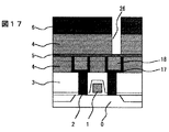
ついで、窒化珪素膜9を50nm、実施の形態1の膜4を400nm形成し、層間接続に相当する孔パタン26を形成した(図17)。この際、銅が露出しないようにエッチングは窒化珪素上で止めた。圧力10mTorrの低圧酸素反応性イオンエッチングを用いてレジストを除去した後、孔底に残存する窒化珪素をエッチングして、銅を露出させた。ついで、スパッタ法で窒化チタン17を50nm、銅18を100nm形成したのち、電解メッキを用いて銅でパタン内を埋め込んだ(図18)。さらに、CMPによりパタン外の銅と窒化チタンを除去して層間接続とした(図19)。
【0043】
さらに、窒化珪素膜9を50nm、<実施の形態1>の膜4を250nm形成し、第2層配線に相当する溝パタン36を形成した(図20)。この際のエッチングは上記と同様である。圧力10mTorrの低圧酸素反応性イオンエッチングを用いてレジストを除去した後、溝底に残存する窒化珪素をエッチングして、銅を露出させた。ついで、スパッタ法で窒化チタン17を50nm、銅18を100nm形成したのち、電解メッキを用いて銅でパタン内を埋め込んだ(図21)。さらに、CMPによりパタン外の銅と窒化チタンを除去して第2層配線とした(図22)。
【0044】
この後さらに、図17から図22と同様の処理を繰り返し、第3層配線を形成した(図23)。
【0045】
上記の工程のすべてで、剥離による問題は生じなかった。
【0046】
比較のために、厚さ100nmの酸化珪素保護膜を用いた試料も作成した。ただし、<実施の形態1>の膜の厚さはすべて100nm減らして、配線高さ、層間接続高さをそろえた。第2層配線間の実効誘電率および上下層配線間の実効誘電率を測定したところ、酸化珪素保護膜がないほうが、約1割実効誘電率が低かった。
【0047】
<実施の形態5>
<実施の形態1>の膜と有機ポリマ膜(ダウケミカル製、商品名SiLK、比誘電率2.7)を用いて、半導体装置の多層配線を作成した。シングルダマシン法により、銅配線を形成する方法を用いた。
【0048】
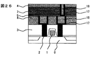
図16の後、窒化珪素膜9を50nm、有機ポリマ膜7を300nm、<実施の形態1>の膜4を100nm形成し、層間接続に相当する孔パタン26を形成した(図24)。この際、まず<実施の形態1>の膜をエッチしておき、ついでこれをハ−ドマスクにして有機ポリマ膜の同時エッチを行った。同時エッチには、酸素・窒素混合ガスによる低圧反応性イオンエッチングを用いた。次に、孔底に残存する窒化珪素をエッチングして、銅を露出させた。ついで、スパッタ法で窒化チタン17を50nm、銅18を100nm形成したのち、電解メッキを用いて銅でパタン内を埋め込んだ(図25)。さらに、CMPによりパタン外の銅と窒化チタンを除去して層間接続とした(図26)。この際、剥離の問題は生じなかった。
【0049】
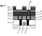
さらに、窒化珪素膜9を50nm、有機ポリマ膜7を150nm、<実施の形態1>の膜4を100nm形成し、第2層配線に相当する溝パタン36を形成した(図27)。この際のエッチングは上記と同様である。次に、溝底に残存する窒化珪素をエッチングして、銅を露出させた。ついで、スパッタ法で窒化チタン17を50nm、銅18を100nm形成したのち、電解メッキを用いて銅でパタン内を埋め込んだ(図28)。さらに、CMPによりパタン外の銅と窒化チタンを除去して第2層配線とした(図29)。
【0050】
この後さらに、図24から図29と同様の処理を繰り返し、第3層配線を形成した(図30)。
【0051】
上記の工程のすべてで、剥離による問題は生じなかった。
【0052】
比較のために、上記の<実施の形態1>の膜をすべて酸化珪素保護膜に代えた試料も作成した。第2層配線間の実効誘電率、および上下層配線間の実効誘電率を測定したところ、実施の形態1の膜を保護膜に用いたほうが、約1割実効誘電率が低かった。
【0053】
<実施の形態6>
<実施の形態1>の膜を用いて、半導体装置の多層配線を作成した。シングルダマシン法に比べて工程数の少ないデュアルダマシン法を用いて、銅配線を形成する方法を用いた。
【0054】
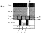
図16の後、窒化珪素膜9を50nm、実施の形態1の膜4を700nm形成し、層間接続に相当する孔パタン26を形成した(図31)。この際、銅が露出しないようにエッチングは窒化珪素上で止めた。圧力10mTorrの低圧酸素反応性イオンエッチングを用いてレジストを除去した後、第2層配線に相当する溝パタン36を形成した(図32)。圧力10mTorrの低圧酸素反応性イオンエッチングを用いてレジスト6を除去した後、孔底に残存する窒化珪素をエッチングして、銅を露出させた。ついで、スパッタ法で窒化チタン17を50nm、銅18を100nm形成したのち、電解メッキを用いて銅でパタン内を埋め込んだ(図33)。さらに、CMPによりパタン外の銅と窒化チタンを除去して層間接続と第2層配線を形成した(図34)。
【0055】
この後さらに、図31から図34と同様の処理を繰り返し、第3層配線を形成した(図35)。
【0056】
上記の工程のすべてで、剥離による問題は生じなかった。
【0057】
<実施の形態7>
<実施の形態1>の膜を用いて、半導体装置の多層配線を作成した。ドライエッチング法により、アルミニウム合金配線を形成する方法を用いた。
【0058】
まず、トランジスタ1,コンタクト2の形成された半導体基板0上に、窒化チタン17,アルミニウム合金19,窒化チタン17をそれぞれ50nm,300nm,50nm形成した。ついで、ホトリソグラフィ−,ドライエッチによって第1層配線を形成し、レジストを除去した(図36)。
【0059】
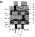
<実施の形態1>の膜を50nm形成した後、厚さ250nmの有機塗布ガラス(日立化成製、商品名HSG−R7)で溝を埋め込んだ後、<実施の形態1>の膜を厚さ1000nm形成した。ついで、化学機械研磨により表面を平坦化した後、層間接続に相当する孔パタンを形成した(図37)。圧力10mTorrの低圧酸素反応性イオンエッチングを用いてレジスト6を除去した後、スパッタ法で窒化チタン17を50nm、CVD法でタングステン20を300nm形成し、孔内を埋め込んだ(図38)。さらに、CMPによりパタン外のタングステンと窒化チタンを除去して層間接続を形成した(図39)。さらに、窒化チタン,アルミニウム合金,窒化チタンをそれぞれ50nm,300nm,50nm形成した。ついでホトリソグラフィ−,ドライエッチによって第2層配線を形成し、レジストを除去した(図40)。この際のレジスト除去にも、圧力10mTorrの低圧酸素反応性イオンエッチングを用いた。
【0060】
この後さらに、図37から図40と同様の処理を繰り返し、第3層配線を形成した(図41)。
【0061】
上記の工程のすべてで、剥離による問題は生じなかった。
【0062】
比較のために、<実施の形態1>の膜の代わりに酸化珪素保護膜を用いた試料も作成した。第2層配線間の実効誘電率および上下層配線間の実効誘電率を測定したところ、酸化珪素膜を用いたものに比べて、隣接配線間は1割、上下層間は2割、実効誘電率が低かった。
【0063】
【発明の効果】
本発明の低誘電率絶縁膜に孔あるいは溝パタンを形成したものに、直接金属膜を形成して研磨しても、金属膜は剥離しない。これは、パタンを形成後のレジスト除去による絶縁膜表面の収縮が小さいためである。
【0064】
したがって、従来の低誘電率膜と酸化珪素保護膜の積層膜を本発明の低誘電率膜で置き換えれば、工程が削減されると共に、酸化珪素膜による実効誘電率増加を防ぐことできる。また、本発明の低誘電率膜を、さらに低誘電率の絶縁膜の保護膜として用いても、酸化珪素膜による実効誘電率増加を削減できる。
【図面の簡単な説明】
【図1】従来の低誘電率層間絶縁膜を用いた半導体装置の製造方法の一例。
【図2】従来の低誘電率層間絶縁膜を用いた半導体装置の製造方法の一例。
【図3】従来の低誘電率層間絶縁膜を用いた半導体装置の製造方法の一例。
【図4】従来の低誘電率層間絶縁膜を用いた半導体装置の製造方法の一例。
【図5】従来の有機シロキサン系層間絶縁膜の問題点の説明図。
【図6】従来の有機シロキサン系層間絶縁膜の問題点の説明図。
【図7】Si−CH3の酸化による体積変化の説明図。
【図8】Si−C−Siが酸化による体積変化の説明図。
【図9】本発明の実施例1で用いるプラズマCVD装置。
【図10】本発明の実施例1のFTIRスペクトル。
【図11】本発明の実施例2のFTIRスペクトルの圧力依存性。
【図12】本発明の実施例2の膜厚減少率の圧力依存性。
【図13】本発明の実施例3の比誘電率と原子数比のn依存性。
【図14】本発明の実施例4の工程説明図。
【図15】本発明の実施例4の工程説明図。
【図16】本発明の実施例4の工程説明図。
【図17】本発明の実施例4の工程説明図。
【図18】本発明の実施例4の工程説明図。
【図19】本発明の実施例4の工程説明図。
【図20】本発明の実施例4の工程説明図。
【図21】本発明の実施例4の工程説明図。
【図22】本発明の実施例4の工程説明図。
【図23】本発明の実施例4の工程説明図。
【図24】本発明の実施例5の工程説明図。
【図25】本発明の実施例5の工程説明図。
【図26】本発明の実施例5の工程説明図。
【図27】本発明の実施例5の工程説明図。
【図28】本発明の実施例5の工程説明図。
【図29】本発明の実施例5の工程説明図。
【図30】本発明の実施例5の工程説明図。
【図31】本発明の実施例6の工程説明図。
【図32】本発明の実施例6の工程説明図。
【図33】本発明の実施例6の工程説明図。
【図34】本発明の実施例6の工程説明図。
【図35】本発明の実施例6の工程説明図。
【図36】本発明の実施例7の工程説明図。
【図37】本発明の実施例7の工程説明図。
【図38】本発明の実施例7の工程説明図。
【図39】本発明の実施例7の工程説明図。
【図40】本発明の実施例7の工程説明図。
【図41】本発明の実施例7の工程説明図。
【符号の説明】
0・・・半導体基板、1・・・トランジスタのゲ−ト電極、2・・・コンタクト電極、3・・・層間絶縁膜、4・・・本発明の層間絶縁膜、5・・・窒化珪素膜、6・・・レジスト、7・・・有機ポリマ系膜、8・・・従来の低誘電率層間絶縁膜、8a・・・従来の有機シロキサン系膜、8b・・・有機シロキサン系膜の酸化層、9・・・酸化珪素膜、10・・・剥離部、16・・・第一層配線用の溝パタン、17・・・バリヤメタル、18・・・銅、19・・・アルミニウム合金、20・・・タングステン、26・・・層間接続用の孔パタン、36・・・第二層配線用の溝パタン。[0001]
BACKGROUND OF THE INVENTION
The present invention relates to a semiconductor device and a manufacturing method thereof, and more particularly to a semiconductor device suitable for high-speed operation and low power consumption and a manufacturing method thereof.
[0002]
[Prior art]
With the miniaturization of the semiconductor element, the parasitic capacitance of the multilayer wiring becomes the same size as the input / output capacitance of the transistor itself, which is a rate-limiting factor of the element operation. In view of this, studies have been actively conducted to introduce an insulating film (hereinafter referred to as a low dielectric constant film in the present invention) having a relative dielectric constant lower than that of conventional silicon oxide (relative dielectric constant˜4).
[0003]
1 to 4 are sectional views showing how to use a low dielectric constant film that has been conventionally studied. In this figure, as an example, a process of forming a buried wiring by the damascene method is shown. First, a
[0004]
Examples of the low dielectric
[0005]
Of these, the fluorinated siloxane-based insulating film is a film having Si—F bonds in the side chain and the main skeleton being Si—O—Si bonds (Proceedings of B.S. Connection Conference, p. 199, 1997). In order to prevent fluorine in the film from reacting with the
[0006]
The organic polymer insulating film is a film whose main skeleton is carbon, and benzocyclobutene-based and aromatic resin-based films are mainly studied. Since both the organic polymer film and the
[0007]
The organosiloxane insulating film is a film having Si—R bonds (R is an organic group) in a side chain and having a main skeleton of Si—O—Si bonds. As R, it is common to use CH3 having excellent heat resistance. In some cases, Si—H may be included as another component. The organic siloxane insulating film has weak adhesion to metals such as titanium nitride and tantalum nitride. Therefore, it is desirable to use the silicon oxide
[0008]
The organic siloxane insulating film can be formed by various chemical vapor deposition methods (CVD) in addition to a method of spin-coating and baking an alcohol solution (organic coating glass solution) of methylalkoxysilane / oligomer. Is being considered.
[0009]
A typical example of the CVD method for an organic siloxane insulating film uses organic silane and an oxidizing gas. For example, Proceedings of International Society for Optical Engineering (SPIE), Vol. 3881, p. 11, 1999, a plasma CVD method using RnSiH4-n and an oxidizing gas was performed in Electrochemical Society Proceedings, Vol. 98-6, p. In 146, 1998, a plasma CVD method using (CH3) 3SiH, N2O, and He was disclosed.
[0010]
In addition, a plasma CVD method using (CH 3) 2 Si (OCH 3) 2 and an inert gas is disclosed in the 60th JSAP Scientific Lecture Proceedings 1p-ZN-9, p. 712, published in 1999. It is necessary to reduce the gas flow rate to about 1/10 of the normal amount and to increase the residence time of the gas in the reaction chamber.
[0011]
[Problems to be solved by the invention]
As described above, the low dielectric constant interlayer insulating film that has been conventionally studied requires a silicon oxide film as a protective film on the upper surface. Considering a practical process margin, the film thickness needs to be at least about 100 nm. This thickness is about 3 of the thickness of the fine wiring (for example, about 300 nm for a device having a gate width of 0.18 μm). Therefore, the effective dielectric constant between adjacent wirings is greatly influenced by the dielectric constant (˜4) of the silicon oxide protective film and becomes higher than the dielectric constant of the low dielectric constant film itself.
[0012]
Among the low dielectric constant films described above, the use of a protective film is inevitable for fluorinated siloxane insulating films and organic polymer insulating films. If the amount of fluorine in the fluorinated siloxane-based insulating film is reduced, the low dielectric constant characteristics of the film are lost. The organic polymer insulating film to resist etching selectivity cannot be essentially high. On the other hand, the organosiloxane insulating film does not contain a component that reacts with a metal like fluorine. The etching selectivity to resist can be increased. Accordingly, if the above problem of peeling can be solved, it can be used without a silicon oxide protective film.
[0013]
However, when the carbon in the film is extremely large as in the case of film formation by the plasma CVD method using (CH3) 3SiH, N2O, and He described in the prior art, the etching ratio with respect to resist cannot be increased. Also, it is clear that reducing the carbon content improves the adhesion, but at the same time, the relative dielectric constant increases.
[0014]
An object of the present invention is to provide a semiconductor device using an organic siloxane insulating film as an interlayer insulating film, which has a low dielectric constant, a high etching selectivity to resist, and does not cause a peeling problem even without a silicon oxide protective film. It is to provide a manufacturing method.
[0015]
[Means for Solving the Problems]
The above problem can be solved by using an organic siloxane insulating film having a small volume change (shrinkage rate) when oxidized.
[0016]
In the case where a metal is simply formed on the organosiloxane insulating film, the metal is simply peeled off from the surface of the insulating film when a peeling force is applied. This is because the organic component (methyl group) in the insulating film inhibits adhesion.
[0017]
However, in the actual process, the peeling mechanism is somewhat different. A
[0018]
It is difficult to directly measure the shrinkage of the surface layer. Therefore, in the present invention, the contraction rate when the inside of the film is sufficiently oxidized, in other words, when the organic component in the film is sufficiently decomposed is used for definition. In order to sufficiently oxidize the inside of the film, for example, oxygen plasma treatment at a high pressure of 1 Torr or more may be performed. The film thickness used for the measurement is preferably about 100 to 300 nm. If it is too thin, the measurement will be inaccurate, and if it is too thick, it will be difficult to oxidize to the inside of the film.
[0019]
By this method, the shrinkage rate when a conventional organosiloxane insulating film (relative permittivity˜3) is oxidized is 20% or more. This is because Si atoms terminated by Si—
[0020]
As an organic component which does not cause shrinkage due to oxidation as described above, there is a Si—C—Si bond. Even if this bond is replaced by a siloxane bond by oxidation, the volume does not change significantly (FIG. 8). Rather it increases slightly. Therefore, if the shrinkage of the organosiloxane insulating film is reduced to 14% or less, preferably 10% or less by replacing a part of the Si—CH3 bond with the Si—C—Si bond, the problem of peeling does not occur. The object of the present invention is achieved.
[0021]
In the organosiloxane insulating film of the present invention, the number of oxygen atoms is preferably 1.5 times or more of the number of silicon atoms, and the number of carbon atoms is preferably 1 to 2 times the number of silicon atoms. If the amount of carbon is small, the film cannot have a low dielectric constant (relative dielectric constant <3.5). Even if there is too little oxygen in the film or too much carbon, the etching selectivity with the resist cannot be increased.
[0022]
The organosiloxane insulating film containing the Si—C—Si bond of the present invention is made of methylalkoxysilane represented by the general formula RnSi (OR ′) 2 -0.5n (where R is
[0023]
In order to form Si—C—Si by the above CVD method, it is desirable that the residence time of the reaction gas in the reaction chamber is short. If the residence time is long, the carbon component of the reaction product increases in the atmosphere in the reaction chamber. As a result, the reaction of decomposing Si—
[0024]
Further, in order to appropriately adjust the amount of carbon and oxygen in the film, n of methylalkoxysilane used as a raw material is desirably 0.75 or more and 1.5 or less. As long as it falls within this range, for example, it may be a single vapor of n = 1 or a mixed vapor of alkoxysilane vapor of n = 0-2. However, it is more preferable to use vapor alone because the structure of the apparatus can be simplified. R 'is not greatly different between CH3 and C2H5, but C2H5 is more desirable because it has an appropriate vapor pressure and is easy to handle.
[0025]
DETAILED DESCRIPTION OF THE INVENTION
Hereinafter, the present invention will be specifically described in embodiments.
[0026]
<
An organic siloxane film having a thickness of 200 nm was formed on a Si substrate by a plasma CVD apparatus having a parallel plate chamber as shown in FIG. The formation conditions are as follows. Liquid source: monomethyltriethoxysilane (CH3Si (OC2H5) 3), bubbler temperature: 37 ° C., carrier He flow rate: 200 sccm,
[0027]
The formed film had a relative dielectric constant of 3.2 and a withstand voltage of 5 MV / cm. When bonding in the film was measured using Fourier transform infrared absorption spectrophotometry (FTIR), Si-CH3 was decomposed in addition to Si-O-Si and Si-CH3. C—Si and Si—H were observed (FIG. 10). The atomic ratio in the film was measured using Auger analysis. The atomic ratio C / Si was 1.6 and O / Si was 1.8. Nitrogen used as a reaction gas was also contained in the film at about 0.1 in N / Si.
[0028]
The above membrane was subjected to oxygen plasma treatment with a barrel type asher apparatus. The processing conditions are oxygen flow rate: 200 sccm, pressure: 1 Torr, RF power: 300 W, time: 15 minutes. The organic content in the film was decomposed and the film was oxidized, but the change in film thickness measured by ellipsometry was less than 5%.
[0029]
The above film was separately formed and subjected to oxygen plasma treatment using a reactive ion etching apparatus. Low pressure conditions used for resist removal from the organosiloxane film were used. The treatment conditions are oxygen flow rate: 50 sccm, pressure: 10 mTorr, RF power: 700 W, time: 1 minute. The organic component in the film was hardly decomposed and the surface was oxidized about 10 nm. On this film, titanium nitride was formed to 50 nm, and then copper was formed to 500 nm. Thereafter, the lattice was scratched with a diamond needle, and a scotch tape peeling test was performed. No titanium nitride and copper delamination was observed.
[0030]
Even if helium, which is an inert gas, was used instead of nitrogen, the results of the above peeling test did not change, but the carbon content in the film was large. This is because there are many unnecessary carbon components that do not contribute to film bonding. In addition, when oxygen was used instead of nitrogen, Si—
[0031]
<
Film formation was performed at different pressures, and the dependence of film quality was investigated. The formation conditions other than the pressure are the same as in <
[0032]
FIG. 11 shows the pressure dependence of the FTIR spectrum. The vertical axis is normalized by the peak value of the Si—O—Si bond having a wave number of 1030 Kaiser. In the figure, the Si—
[0033]
When the pressure is high, Si-CH3 is large and Si-H is small. The wave number with the maximum peak between 750 and 850 Kaiser is 770 Kaiser. This indicates that a reaction in which Si—
[0034]
FIG. 12 shows the rate of film thickness reduction by the barrel type asher. The conditions of the barrel type asher are the same as those in <
[0035]
In order to perform a peel test, an insulating film having a thickness of 200 nm was formed on a Si substrate, and then low-pressure oxygen plasma treatment was performed to form titanium nitride and copper. These conditions are the same as in <
[0036]
<
Films were formed by changing the liquid source material, and the material existence of the film quality was examined. When two liquid sources were used, two bubblers were used that could independently control the temperature of each bubbler and the carrier He flow rate. Thus, the total carrier He flow rate was adjusted to 200 sccm, and the liquid source vapor amount in the carrier was adjusted to be equal to that in the first embodiment. All other formation conditions are the same as those in the first embodiment.
[0037]
The amount of liquid source vapor in the carrier gas of 200 sccm is shown below (relative value where the vapor amount of <
[0038]
FIG. 13 shows the relationship between the relative dielectric constant, the O / Si ratio in the film, the C / Si ratio and n. From this, in order to realize a dielectric constant of 3.5 or less, an O / Si ratio of 1.5 or more, and a C / Si ratio of 1 or more and 2 or less, n may be 0.5 to 1.5. all right.
[0039]
In addition, oxygen plasma treatment was applied to the above film with a barrel type asher device. The processing conditions are the same as in <
[0040]
<
Using the film of <
[0041]
First, the
[0042]
Next, the
[0043]
Further, the
[0044]
Thereafter, the same processing as in FIGS. 17 to 22 was repeated to form the third layer wiring (FIG. 23).
[0045]
In all of the above steps, no problems due to peeling occurred.
[0046]
For comparison, a sample using a 100 nm thick silicon oxide protective film was also prepared. However, the film thicknesses of <
[0047]
<
Using the film of <
[0048]
After FIG. 16, the
[0049]
Further, the
[0050]
Thereafter, the same processing as in FIGS. 24 to 29 was repeated to form the third layer wiring (FIG. 30).
[0051]
In all of the above steps, no problems due to peeling occurred.
[0052]
For comparison, a sample in which the film of <
[0053]
<
Using the film of <
[0054]
After FIG. 16, the
[0055]
Thereafter, the same processing as in FIGS. 31 to 34 was repeated to form the third layer wiring (FIG. 35).
[0056]
In all of the above steps, no problems due to peeling occurred.
[0057]
<
Using the film of <
[0058]
First, on the
[0059]
After the film of <
[0060]
Thereafter, the same processing as in FIGS. 37 to 40 was repeated to form a third layer wiring (FIG. 41).
[0061]
In all of the above steps, no problems due to peeling occurred.
[0062]
For comparison, a sample using a silicon oxide protective film instead of the film of <
[0063]
【The invention's effect】
Even if a metal film is directly formed and polished on the low dielectric constant insulating film of the present invention in which holes or groove patterns are formed, the metal film does not peel off. This is because the shrinkage of the insulating film surface due to the removal of the resist after forming the pattern is small.
[0064]
Therefore, if the conventional laminated film of the low dielectric constant film and the silicon oxide protective film is replaced with the low dielectric constant film of the present invention, the number of steps can be reduced and an increase in the effective dielectric constant due to the silicon oxide film can be prevented. Even if the low dielectric constant film of the present invention is used as a protective film for an insulating film having a lower dielectric constant, an increase in effective dielectric constant due to the silicon oxide film can be reduced.
[Brief description of the drawings]
FIG. 1 shows an example of a conventional method for manufacturing a semiconductor device using a low dielectric constant interlayer insulating film.
FIG. 2 shows an example of a conventional method for manufacturing a semiconductor device using a low dielectric constant interlayer insulating film.
FIG. 3 shows an example of a conventional method for manufacturing a semiconductor device using a low dielectric constant interlayer insulating film.
FIG. 4 shows an example of a conventional method for manufacturing a semiconductor device using a low dielectric constant interlayer insulating film.
FIG. 5 is an explanatory diagram of problems of a conventional organosiloxane interlayer insulating film.
FIG. 6 is an explanatory diagram of problems of a conventional organosiloxane interlayer insulating film.
FIG. 7 is an explanatory diagram of a volume change due to oxidation of Si—
FIG. 8 is an explanatory view of a volume change due to oxidation of Si—C—Si.
FIG. 9 shows a plasma CVD apparatus used in Example 1 of the present invention.
FIG. 10 is an FTIR spectrum of Example 1 of the present invention.
FIG. 11 shows the pressure dependence of the FTIR spectrum of Example 2 of the present invention.
FIG. 12 shows the pressure dependence of the film thickness reduction rate in Example 2 of the present invention.
FIG. 13 shows n dependency of relative permittivity and atomic ratio in Example 3 of the present invention.
FIG. 14 is a process explanatory diagram of
FIG. 15 is a process explanatory diagram of
FIG. 16 is a process explanatory diagram of
FIG. 17 is a process explanatory diagram of
FIG. 18 is a process explanatory diagram of
FIG. 19 is a process explanatory diagram of
FIG. 20 is a process explanatory diagram of
FIG. 21 is a process explanatory diagram of
FIG. 22 is a process explanatory diagram of
FIG. 23 is a process explanatory diagram of
FIG. 24 is a process explanatory diagram of
FIG. 25 is a process explanatory diagram of
FIG. 26 is a process explanatory diagram of
FIG. 27 is a process explanatory diagram of
FIG. 28 is a process explanatory diagram of
FIG. 29 is a process explanatory diagram of
FIG. 30 is a process explanatory diagram of
FIG. 31 is a process explanatory diagram of
FIG. 32 is a process explanatory diagram of
FIG. 33 is a process explanatory diagram of
FIG. 34 is a process explanatory diagram of
FIG. 35 is a process explanatory diagram of
FIG. 36 is a process explanatory diagram of
FIG. 37 is a process explanatory diagram of
FIG. 38 is a process explanatory diagram of
FIG. 39 is a process explanatory diagram of
FIG. 40 is a process explanatory diagram of
41 is a process explanatory diagram of
[Explanation of symbols]
DESCRIPTION OF
Claims (21)
Priority Applications (5)
| Application Number | Priority Date | Filing Date | Title |
|---|---|---|---|
| JP2000013895A JP3615979B2 (en) | 2000-01-18 | 2000-01-18 | Semiconductor device and manufacturing method thereof |
| TW090101031A TW513763B (en) | 2000-01-18 | 2001-01-17 | Semiconductor device and process for producing the same |
| US09/760,777 US6358838B2 (en) | 2000-01-18 | 2001-01-17 | Semiconductor device and process for producing the same |
| KR1020010002929A KR100689917B1 (en) | 2000-01-18 | 2001-01-18 | Semiconductor device and process for producing the same |
| US10/050,859 US6680541B2 (en) | 2000-01-18 | 2002-01-18 | Semiconductor device and process for producing the same |
Applications Claiming Priority (1)
| Application Number | Priority Date | Filing Date | Title |
|---|---|---|---|
| JP2000013895A JP3615979B2 (en) | 2000-01-18 | 2000-01-18 | Semiconductor device and manufacturing method thereof |
Publications (3)
| Publication Number | Publication Date |
|---|---|
| JP2001203200A JP2001203200A (en) | 2001-07-27 |
| JP2001203200A5 JP2001203200A5 (en) | 2004-12-24 |
| JP3615979B2 true JP3615979B2 (en) | 2005-02-02 |
Family
ID=18541427
Family Applications (1)
| Application Number | Title | Priority Date | Filing Date |
|---|---|---|---|
| JP2000013895A Expired - Fee Related JP3615979B2 (en) | 2000-01-18 | 2000-01-18 | Semiconductor device and manufacturing method thereof |
Country Status (4)
| Country | Link |
|---|---|
| US (2) | US6358838B2 (en) |
| JP (1) | JP3615979B2 (en) |
| KR (1) | KR100689917B1 (en) |
| TW (1) | TW513763B (en) |
Families Citing this family (33)
| Publication number | Priority date | Publication date | Assignee | Title |
|---|---|---|---|---|
| JP2000174123A (en) * | 1998-12-09 | 2000-06-23 | Nec Corp | Semiconductor device and manufacture thereof |
| US6500752B2 (en) * | 2000-07-21 | 2002-12-31 | Canon Sales Co., Inc. | Semiconductor device and semiconductor device manufacturing method |
| WO2002017693A1 (en) * | 2000-08-18 | 2002-02-28 | Mitsubishi Denki Kabushiki Kaisha | Installation substrate, method of mounting installation substrate, and bulb socket using installation substrate |
| JP2002329722A (en) * | 2001-04-27 | 2002-11-15 | Nec Corp | Semiconductor device and its manufacturing method |
| US6699792B1 (en) * | 2001-07-17 | 2004-03-02 | Advanced Micro Devices, Inc. | Polymer spacers for creating small geometry space and method of manufacture thereof |
| US6887780B2 (en) * | 2001-08-31 | 2005-05-03 | Intel Corporation | Concentration graded carbon doped oxide |
| JP3913638B2 (en) * | 2001-09-03 | 2007-05-09 | 東京エレクトロン株式会社 | Heat treatment method and heat treatment apparatus |
| JP2003092349A (en) * | 2001-09-18 | 2003-03-28 | Mitsubishi Electric Corp | Semiconductor device and manufacturing method therefor |
| JP4063619B2 (en) * | 2002-03-13 | 2008-03-19 | Necエレクトロニクス株式会社 | Manufacturing method of semiconductor device |
| JP3516446B2 (en) | 2002-04-26 | 2004-04-05 | 東京応化工業株式会社 | Photoresist stripping method |
| US7071112B2 (en) * | 2002-10-21 | 2006-07-04 | Applied Materials, Inc. | BARC shaping for improved fabrication of dual damascene integrated circuit features |
| US6867126B1 (en) * | 2002-11-07 | 2005-03-15 | Taiwan Semiconductor Manufacturing Company, Ltd. | Method to increase cracking threshold for low-k materials |
| US20040152295A1 (en) * | 2003-02-03 | 2004-08-05 | International Business Machines Corporation | Sacrificial metal liner for copper |
| US7279410B1 (en) | 2003-03-05 | 2007-10-09 | Advanced Micro Devices, Inc. | Method for forming inlaid structures for IC interconnections |
| US8137764B2 (en) * | 2003-05-29 | 2012-03-20 | Air Products And Chemicals, Inc. | Mechanical enhancer additives for low dielectric films |
| US6767827B1 (en) | 2003-06-11 | 2004-07-27 | Advanced Micro Devices, Inc. | Method for forming dual inlaid structures for IC interconnections |
| US6919636B1 (en) | 2003-07-31 | 2005-07-19 | Advanced Micro Devices, Inc. | Interconnects with a dielectric sealant layer |
| TWI285938B (en) * | 2003-08-28 | 2007-08-21 | Fujitsu Ltd | Semiconductor device |
| JP4282493B2 (en) * | 2004-01-15 | 2009-06-24 | 株式会社東芝 | Film forming method and substrate processing apparatus |
| TW200605220A (en) * | 2004-06-21 | 2006-02-01 | Hitachi Chemical Co Ltd | Organic siloxane film, semiconductor device using same, flat panel display and raw material liquid |
| JP4854938B2 (en) | 2004-07-06 | 2012-01-18 | ルネサスエレクトロニクス株式会社 | Semiconductor device and manufacturing method thereof |
| US7202564B2 (en) * | 2005-02-16 | 2007-04-10 | International Business Machines Corporation | Advanced low dielectric constant organosilicon plasma chemical vapor deposition films |
| US7332428B2 (en) * | 2005-02-28 | 2008-02-19 | Infineon Technologies Ag | Metal interconnect structure and method |
| US7214612B2 (en) * | 2005-08-31 | 2007-05-08 | United Microelectronics Corp. | Dual damascene structure and fabrication thereof |
| US7410899B2 (en) * | 2005-09-20 | 2008-08-12 | Enthone, Inc. | Defectivity and process control of electroless deposition in microelectronics applications |
| JP5154009B2 (en) * | 2005-10-21 | 2013-02-27 | 株式会社ジャパンディスプレイイースト | Manufacturing method of organic siloxane insulating film, and manufacturing method of liquid crystal display device using organic siloxane insulating film manufactured by this manufacturing method as interlayer insulation |
| JP5168142B2 (en) * | 2006-05-17 | 2013-03-21 | 日本電気株式会社 | Semiconductor device |
| US8637396B2 (en) | 2008-12-01 | 2014-01-28 | Air Products And Chemicals, Inc. | Dielectric barrier deposition using oxygen containing precursor |
| EP2306506B1 (en) * | 2009-10-01 | 2013-07-31 | ams AG | Method of producing a semiconductor device having a through-wafer interconnect |
| JP2013020530A (en) * | 2011-07-13 | 2013-01-31 | Dainippon Printing Co Ltd | Touch sensor panel member, display device with touch sensor panel member, and method of manufacturing touch sensor panel member |
| US10319630B2 (en) * | 2012-09-27 | 2019-06-11 | Stmicroelectronics, Inc. | Encapsulated damascene interconnect structure for integrated circuits |
| US8980740B2 (en) | 2013-03-06 | 2015-03-17 | Globalfoundries Inc. | Barrier layer conformality in copper interconnects |
| KR20200102620A (en) * | 2019-02-21 | 2020-09-01 | 삼성디스플레이 주식회사 | Photopolymerizable resin composition, display device using same and manufacturing method therof |
Family Cites Families (13)
| Publication number | Priority date | Publication date | Assignee | Title |
|---|---|---|---|---|
| US5407529A (en) * | 1992-03-04 | 1995-04-18 | Nec Corporation | Method for manufacturing semiconductor device |
| US6423651B1 (en) * | 1993-12-27 | 2002-07-23 | Kawasaki Steel Corporation | Insulating film of semiconductor device and coating solution for forming insulating film and method of manufacturing insulating film |
| US6326318B1 (en) * | 1995-09-14 | 2001-12-04 | Sanyo Electric Co., Ltd. | Process for producing semiconductor devices including an insulating layer with an impurity |
| US5989998A (en) * | 1996-08-29 | 1999-11-23 | Matsushita Electric Industrial Co., Ltd. | Method of forming interlayer insulating film |
| JP3726226B2 (en) | 1998-02-05 | 2005-12-14 | 日本エー・エス・エム株式会社 | Insulating film and manufacturing method thereof |
| US6054379A (en) * | 1998-02-11 | 2000-04-25 | Applied Materials, Inc. | Method of depositing a low k dielectric with organo silane |
| US6068884A (en) * | 1998-04-28 | 2000-05-30 | Silcon Valley Group Thermal Systems, Llc | Method of making low κ dielectric inorganic/organic hybrid films |
| US6383951B1 (en) * | 1998-09-03 | 2002-05-07 | Micron Technology, Inc. | Low dielectric constant material for integrated circuit fabrication |
| US6255232B1 (en) * | 1999-02-11 | 2001-07-03 | Taiwan Semiconductor Manufacturing Company | Method for forming low dielectric constant spin-on-polymer (SOP) dielectric layer |
| US6312793B1 (en) * | 1999-05-26 | 2001-11-06 | International Business Machines Corporation | Multiphase low dielectric constant material |
| US6225238B1 (en) * | 1999-06-07 | 2001-05-01 | Allied Signal Inc | Low dielectric constant polyorganosilicon coatings generated from polycarbosilanes |
| EP1077479A1 (en) * | 1999-08-17 | 2001-02-21 | Applied Materials, Inc. | Post-deposition treatment to enchance properties of Si-O-C low K film |
| US6365528B1 (en) * | 2000-06-07 | 2002-04-02 | Lsi Logic Corporation | Low temperature process for forming a low dielectric constant fluorine and carbon-containing silicon oxide dielectric-material characterized by improved resistance to oxidation and good gap-filling capabilities |
-
2000
- 2000-01-18 JP JP2000013895A patent/JP3615979B2/en not_active Expired - Fee Related
-
2001
- 2001-01-17 TW TW090101031A patent/TW513763B/en not_active IP Right Cessation
- 2001-01-17 US US09/760,777 patent/US6358838B2/en not_active Expired - Lifetime
- 2001-01-18 KR KR1020010002929A patent/KR100689917B1/en not_active IP Right Cessation
-
2002
- 2002-01-18 US US10/050,859 patent/US6680541B2/en not_active Expired - Lifetime
Also Published As
| Publication number | Publication date |
|---|---|
| US20010009295A1 (en) | 2001-07-26 |
| KR20010076349A (en) | 2001-08-11 |
| JP2001203200A (en) | 2001-07-27 |
| US6358838B2 (en) | 2002-03-19 |
| US20020105085A1 (en) | 2002-08-08 |
| US6680541B2 (en) | 2004-01-20 |
| KR100689917B1 (en) | 2007-03-09 |
| TW513763B (en) | 2002-12-11 |
Similar Documents
| Publication | Publication Date | Title |
|---|---|---|
| JP3615979B2 (en) | Semiconductor device and manufacturing method thereof | |
| TW432476B (en) | A silicon carbide deposition for use as a barrier layer and an etch stop | |
| US7763979B2 (en) | Organic insulating film, manufacturing method thereof, semiconductor device using such organic insulating film and manufacturing method thereof | |
| KR100696033B1 (en) | Method of processing a semiconductor substrate | |
| JP4090740B2 (en) | Integrated circuit manufacturing method and integrated circuit | |
| JP4338495B2 (en) | Silicon oxycarbide, semiconductor device, and method of manufacturing semiconductor device | |
| US20030089992A1 (en) | Silicon carbide deposition for use as a barrier layer and an etch stop | |
| JP4068072B2 (en) | Semiconductor device and manufacturing method thereof | |
| WO2000054329A1 (en) | Semiconductor device and production method therefor | |
| JP5174435B2 (en) | Method for minimizing wet etch undercut and pore sealing ultra-low K (K <2.5) dielectrics | |
| US7960279B2 (en) | Semiconductor device and manufacturing method therefor | |
| US20030001278A1 (en) | Method for manufacturing a semiconductor device and a semiconductor device | |
| JP2010267971A (en) | Dielectric barrier deposition using nitrogen containing precursor | |
| US20050176216A1 (en) | Ultra low dielectric constant thin film | |
| US6784485B1 (en) | Diffusion barrier layer and semiconductor device containing same | |
| JP3768480B2 (en) | Semiconductor device and manufacturing method thereof | |
| JP3184177B2 (en) | Method for forming interlayer insulating film, semiconductor manufacturing apparatus, and semiconductor device | |
| JP4882893B2 (en) | Manufacturing method of semiconductor device | |
| Ohto et al. | Method for manufacturing a semiconductor device having a multi-layered insulating structure of SiOCH layers and an SiO 2 layer |
Legal Events
| Date | Code | Title | Description |
|---|---|---|---|
| A521 | Request for written amendment filed |
Free format text: JAPANESE INTERMEDIATE CODE: A523 Effective date: 20040114 |
|
| A621 | Written request for application examination |
Free format text: JAPANESE INTERMEDIATE CODE: A621 Effective date: 20040114 |
|
| A521 | Request for written amendment filed |
Free format text: JAPANESE INTERMEDIATE CODE: A523 Effective date: 20040114 |
|
| RD02 | Notification of acceptance of power of attorney |
Free format text: JAPANESE INTERMEDIATE CODE: A7422 Effective date: 20040309 |
|
| A977 | Report on retrieval |
Free format text: JAPANESE INTERMEDIATE CODE: A971007 Effective date: 20041005 |
|
| TRDD | Decision of grant or rejection written | ||
| A01 | Written decision to grant a patent or to grant a registration (utility model) |
Free format text: JAPANESE INTERMEDIATE CODE: A01 Effective date: 20041012 |
|
| A61 | First payment of annual fees (during grant procedure) |
Free format text: JAPANESE INTERMEDIATE CODE: A61 Effective date: 20041102 |
|
| R150 | Certificate of patent or registration of utility model |
Free format text: JAPANESE INTERMEDIATE CODE: R150 |
|
| S111 | Request for change of ownership or part of ownership |
Free format text: JAPANESE INTERMEDIATE CODE: R313117 |
|
| R350 | Written notification of registration of transfer |
Free format text: JAPANESE INTERMEDIATE CODE: R350 |
|
| FPAY | Renewal fee payment (event date is renewal date of database) |
Free format text: PAYMENT UNTIL: 20071112 Year of fee payment: 3 |
|
| FPAY | Renewal fee payment (event date is renewal date of database) |
Free format text: PAYMENT UNTIL: 20081112 Year of fee payment: 4 |
|
| FPAY | Renewal fee payment (event date is renewal date of database) |
Free format text: PAYMENT UNTIL: 20081112 Year of fee payment: 4 |
|
| FPAY | Renewal fee payment (event date is renewal date of database) |
Free format text: PAYMENT UNTIL: 20091112 Year of fee payment: 5 |
|
| FPAY | Renewal fee payment (event date is renewal date of database) |
Free format text: PAYMENT UNTIL: 20101112 Year of fee payment: 6 |
|
| FPAY | Renewal fee payment (event date is renewal date of database) |
Free format text: PAYMENT UNTIL: 20111112 Year of fee payment: 7 |
|
| FPAY | Renewal fee payment (event date is renewal date of database) |
Free format text: PAYMENT UNTIL: 20111112 Year of fee payment: 7 |
|
| S111 | Request for change of ownership or part of ownership |
Free format text: JAPANESE INTERMEDIATE CODE: R313111 |
|
| FPAY | Renewal fee payment (event date is renewal date of database) |
Free format text: PAYMENT UNTIL: 20111112 Year of fee payment: 7 |
|
| R350 | Written notification of registration of transfer |
Free format text: JAPANESE INTERMEDIATE CODE: R350 |
|
| FPAY | Renewal fee payment (event date is renewal date of database) |
Free format text: PAYMENT UNTIL: 20111112 Year of fee payment: 7 |
|
| FPAY | Renewal fee payment (event date is renewal date of database) |
Free format text: PAYMENT UNTIL: 20121112 Year of fee payment: 8 |
|
| FPAY | Renewal fee payment (event date is renewal date of database) |
Free format text: PAYMENT UNTIL: 20121112 Year of fee payment: 8 |
|
| FPAY | Renewal fee payment (event date is renewal date of database) |
Free format text: PAYMENT UNTIL: 20131112 Year of fee payment: 9 |
|
| S531 | Written request for registration of change of domicile |
Free format text: JAPANESE INTERMEDIATE CODE: R313531 |
|
| R350 | Written notification of registration of transfer |
Free format text: JAPANESE INTERMEDIATE CODE: R350 |
|
| LAPS | Cancellation because of no payment of annual fees |


