JP3614274B2 - Paper post-processing apparatus and image forming apparatus - Google Patents
Paper post-processing apparatus and image forming apparatus Download PDFInfo
- Publication number
- JP3614274B2 JP3614274B2 JP10483997A JP10483997A JP3614274B2 JP 3614274 B2 JP3614274 B2 JP 3614274B2 JP 10483997 A JP10483997 A JP 10483997A JP 10483997 A JP10483997 A JP 10483997A JP 3614274 B2 JP3614274 B2 JP 3614274B2
- Authority
- JP
- Japan
- Prior art keywords
- paper
- sheet
- discharge tray
- tray
- discharge
- Prior art date
- Legal status (The legal status is an assumption and is not a legal conclusion. Google has not performed a legal analysis and makes no representation as to the accuracy of the status listed.)
- Expired - Fee Related
Links
Images


Description
【0001】
【発明の属する技術分野】
本発明は、複写機、プリンタ、ファクシミリなどの画像形成装置の排紙部に連結される用紙後処理装置およびその用紙後処理装置を備えた画像形成装置に関する。
【0002】
【従来の技術】
画像形成装置から排出される用紙をスティプルトレイに受け入れてその端部をスティプル処理するためのスティプルユニットと、スティプルユニットによりスティプル処理された用紙束をスティプルトレイ外へ放出する放出手段と、放出された用紙束を受け取りスタックする排紙トレイと、排紙トレイを上下方向に駆動する駆動手段とを備えた用紙後処理装置が提案されている。
このような用紙後処理装置において、スティプルされた用紙束の先端部(スティプルされた端部と反対側の端部)が下向きにカールしていると、排紙トレイにこの用紙を排紙する際、カール部分が折れ曲がったり、丸まった状態で排紙トレイ面にスタックされることになる。
用紙のサイズが大きい場合、あるいは用紙が薄紙の場合、さらにはスティプルされた用紙枚数が多い場合も、排紙部と排紙トレイ面の間に距離があるとやはり下方に垂れ下がることがあり、上記と同様の状態になる。
【0003】
【発明が解決しようとする課題】
上述したように、従来の用紙後処理装置では、用紙に下向きのカールが発生していた場合、あるいは用紙のサイズ、種類、枚数によっては、下から何枚かの用紙が丸まった状態で排紙トレイ上にスタックされることになり、用紙束に折れが生じるという不具合がある。また、高さ方向に不必要に嵩張ってしまい、所定の部数をスタックすることができないため、スタック効率が悪いという問題もある。
【0004】
本発明の課題は、排紙トレイ上に排紙される用紙束のスタック不良や紙折れを回避することができる用紙後処理装置および画像形成装置を提供することである。
【0005】
【課題を解決するための手段】
上記課題は、搬送されてくる用紙を受け入れ、複数の用紙をスティプル処理するスティプル手段と、スティプル処理された用紙束を積載する上下移動可能な排紙トレイとを備えた用紙後処理装置において、スティプルされた用紙束を前記排紙トレイ上に放出するに際し、一時的に前記排紙トレイを所定の上方位置へ上昇させる制御手段を備え、前記制御手段は、スティプルされた用紙束の綴じ枚数が所定の枚数より多い場合には、前記所定の上方位置を更に上方の位置へ調整する第1の手段により解決される。
上記課題は、搬送されてくる用紙を受け入れ、複数の用紙をスティプル処理するスティプル手段と、スティプル処理された用紙束を積載する上下移動可能な排紙トレイとを備えた用紙後処理装置において、スティプルされた用紙束を前記排紙トレイ上に放出するに際し、一時的に前記排紙トレイを所定の上方位置へ上昇させる制御手段を備え、前記制御手段は、スティプルされた用紙束の用紙サイズが所定のサイズより大きい場合には、前記所定の上方位置を更に上方の位置へ調整する第2の手段により解決される。
上記課題は、第1または2の手段において、前記上方位置は前記排紙トレイに用紙を放出する放出口の下方近傍である第3の手段により解決される。
上記課題は、第1ないし3の手段の用紙後処理装置を備えた第4の手段により解決される。
【0006】
【発明の実施の形態】
以下、本発明の実施の形態を図面に基づいて説明する。
【0007】
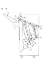
図1は本発明の実施の形態に係る用紙後処理装置全体の構成図、図2はジョガーフェンスと戻しローラの駆動機構を示す斜視図、図3は後端フェンス部近傍の第1の例を示す拡大構成図、図4はスティプル装置を中心とした斜視図、図5は綴じ後の用紙束を放出ベルトにより放出する様子を示す透視斜視図、図6は本発明の実施の形態に係る用紙後処理装置の電装系のブロック図である。
【0008】
図1において、複写機からの用紙排出搬送路入口に、排紙センサ36、入口ローラ1、及び分岐爪8が設けられ、この分岐爪8により、排紙トレイ12方向へ行く用紙(記録紙)と、スティプル装置(スティプルユニット)11方向へ行く用紙とが分けられる。
排紙トレイ12方向の搬送路には、複数の上搬送ローラ2、排紙センサ38、排出ローラ3、用紙を一方に寄せる寄せローラ7、積載用紙により上下する紙面レバー13、積載用紙高さを検出する紙面センサ33などが配置され、スティプル装置11方向の搬送路には、複数の下搬送ローラ4、排紙センサ37、紙送りローラ(ブラシローラ)6等が配置されている。
下搬送ローラ4は、後述する搬送モータ54により駆動され、排紙トレイ12は、後述する上下モータ51、シフトモータ52により適宜上下左右に移動される。
スティプル装置11は、スティプルトレイ21の下側に設けられ、スティプルトレイ21には、用紙の整合を行うためのジョガーフェンス9、及び戻しローラ5、ジョガーフェンス9の背後位置に綴じた用紙束を排出するための放出ベルト10がそれぞれ配置されている。39は放出ベルトホームセンサである。
このジョガーフェンス9は、図2に示すように、ジョガーモータ26によりジョガーベルト49を介して用紙の幅方向に駆動され、戻しローラ5は、戻しソレノイド30により用紙面に接離するような振り子運動されるように構成されている。
【0009】
また、ブラシローラ6は、ブラシローラベルト47により図3の矢印方向に回転するようになっている。ジョガーフェンス9の下側には、図3に示すように、用紙後端に突き当てるための後端フェンス19が設けられている。
また、スティプル装置11は、図4に示すように、スティプラ移動モータ27によりスティプルベルト50を介して駆動され、横移動する。22はスティプラホームセンサである。後端フェンス19は、固定片19a,19bと、スティプル装置11が移動する際に一緒に移動する可動片19c,19dを有する。
ところで、排紙センサ37は、用紙後端を検知して即、戻しソレノイド30にオン命令を出して戻しローラ5を作動させても、そのタイミングで戻しローラ5が用紙の後端に打ち当て可能になるような位置に配置されている。
また、図5に示すように、スティプル装置11により綴じられた用紙束の後端は、放出ベルト10に設けられた放出爪10aに係止され、放出モータ57により駆動される放出ベルト10の回転により排紙トレイ12に排出されるようになっている。
【0010】
ここで、本発明の実施の形態に係る用紙後処理装置の電装系について図6を参照して説明する。
図6に示すように、用紙後処理装置内の各スイッチ、及び各センサからの信号が、I/Oインタフェース60を介してCPU70へ入力される。CPU70は、入力された信号に応じて、上下モータ51、シフトモータ52、分岐ソレノイド53、戻しソレノイド30、搬送モータ54、排紙モータ55、スティプルモータ56、放出モータ57、スティプラ移動モータ27、ジョガーモータ26を駆動する。搬送モータ54のパルス信号は、CPU70に入力されてカウントされ、このカウントに応じて戻しソレノイド30が制御される。用紙整合制御手段は、CPU70及びCPU70を動かす種々のオペレーションプログラムによって構成される。
【0011】
次に、前記実施の形態において、まずスティプルを行わないノンスティプルモードが選択された場合の動作について説明する。
コピー済みの用紙が、入口ローラ1により受け入れられ、上搬送ローラ2で送られ、排出ローラ3により排紙トレイ12上に排出される。そして、寄せローラ7により用紙の縦方向の整合が行われ、排紙トレイ12にスタックされる。
このとき、寄せローラ7は、排紙センサ38が用紙後端を検知すると減速され、スタック性を向上させる。また、順次コピー済みの用紙が排出されていくと、紙面レバー13が上昇し(時計回り方向に揺動し)、これを紙面センサ33が検出し、上下モータ51の駆動により、排紙トレイ12は下げられ、常に適切な高さに保たれる。
また、ソート及びスタックモード時には、装置本体のコントロールパネルなどから出される仕切信号により、排紙トレイ12をシフトモータ52により左右にシフトさせ、ジョブ終了まで仕分けを行う。また、ジョブ終了時には、排紙トレイ12を30ミリメートル程度下降する。
【0012】
次に、スティプルモードが選択された場合について説明する。
スティプルモードが選択されると、図2に示すように、ジョガーフェンス9は、ホームポジションより移動し、用紙幅より片側7ミリメートル離れた位置で待機する。用紙が下搬送ローラ4(搬送モータ54で駆動される)によって搬送され、用紙後端が排紙センサ37を通過すると、ジョガーフェンス9が待機位置から5ミリメートル内側にジョギング(矢印方向の往復運動)を行う。
また、排紙センサ37は、用紙後端通過時点にそれを検知し、その信号をCPU70に入力し、CPU70では、この信号の受信時点から搬送モータ54からの発信パルスをカウントし、所定パルス発信後に戻しソレノイド30をオンさせる。
戻しローラ5は、戻しソレノイド30のオン、オフにより振り子運動をし、オン時には用紙を叩いて下方向に戻し、後端フェンス19に突き当てて用紙の縦揃えを行う。スティプルトレイ21に収納されている用紙が入口センサ36(あるいは排紙センサ37)を通過する度にその信号がCPU70に入力されて、用紙の枚数がカウントされる。
この戻しソレノイド30がオフして所定時間経過後、ジョガーフェンス9は、ジョガーモータ26によって2ミリメートル内側に移動して一旦停止し、用紙の横揃えが終了する。ジョガーフェンス9は、その後7ミリメートル戻り、次の用紙を待つ。この動作を最終頁まで行う。最終頁では、再び7ミリメートルのジョギングを行い、用紙束の両端を押さえてスティプル動作に備える。
【0013】
その後、所定時間後にスティプル装置11が作動し、綴じ処理が行われる。このとき、複数綴じが指定されていれば、1個所の綴じ処理が終了した後、スティプル移動モータ27が駆動され、スティプル装置11が用紙後端に沿って適正位置まで移動され、2個所目の綴じ処理が行われる。
綴じ処理が終了すると、放出モータ57が駆動され、放出ベルト10を駆動する。このとき、排紙モータ55も駆動され、放出爪10aにより持ち上げられた用紙束を受け取るべく回転し始める。このとき、ジョガーフェンス9は、サイズ及び枚数により動作が異なるように制御される。
例えば、綴じ枚数が設定枚数より少ない、あるいは設定サイズより小さい場合には、ジョガーフェンス9により用紙束を押さえながら、放出爪10aにより用紙束後端を引っ掛け搬送する。
そして、放出ベルトホームセンサ39より、所定パルス後にジョガーフェンス9を2ミリメートル退避させ、ジョガーフェンス9による用紙への拘束を解除する(この所定パルスは、放出爪10aが用紙束後端に衝突してから、ジョガーフェンス9の先端を抜ける間で設定されている)。
また、綴じ枚数が設定枚数より多い、あるいは設定サイズより大きい場合には、予めジョガーフェンス9を2ミリメートル退避させ、放出を行う。何れの場合も、用紙束がジョガーフェンス9を抜けきると、ジョガーフェンス9はさらに5ミリメートル移動して待機位置に復帰し、次の用紙に備える。また、用紙に対するジョガーフェンス9の距離により、拘束力を調節することも可能である。
以上の一連の動作をラストジョブまで繰り返し行う。
【0014】
図7は排紙トレイ上下機構を示す透視斜視図である。
排紙トレイ12は、図7に示すように、上下リフトベルト48により吊るされている。上下リフトベルト48は、ギヤ列及びタイミングベルトを介して上下モータ51により駆動され、上下モータ51の正転または逆転により上昇または下降する。
排紙トレイ12のホームポジション及び移動時の高さは、上下方向に回動可能な紙面レバー13と紙面センサ32,33により検出され、また、排紙トレイ12上が用紙で満杯になると、下限センサ34によりこれが検出される。さらに、排紙トレイ12の上昇時に、寄せローラ7が排紙トレイ12により押し上げられると、上限スイッチ31がオフになり、上下モータ51が回転を停止することにより、排紙トレイ12のオーバランによる破損を防止している。
【0015】
図8は排紙トレイにスタックされた用紙束の状態を示す図である。
前述のように、排紙トレイ12の面、あるいはこの例では既に排紙トレイ12にスタックされている用紙束P1の上面が排紙部よりかなり下方にあると、次に排紙されてくる用紙束P2に下向きのカールが発生している場合、図に示すように、この部分が丸まった状態でスタックされてしまう。
【0016】
本発明は、用紙束を排紙トレイ12にスタックするときは、排紙トレイ12の高さを常に上方にセットして、用紙束の後端が排出ローラ3より排出されると、排紙トレイ12を所定距離下に移動させる。移動後は所定時間経過すると、排紙トレイ12を再び上方に移動して次の用紙束の排出に備える。
このように、用紙束の先端が常に高い位置にある排紙トレイ12にスタックされるように排紙トレイ12を制御することを特徴としている。即ち、垂れ下がる量が多くなる前に排紙トレイ12に用紙束をスタックさせてしまうものである。
【0017】
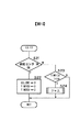
図9はトレイ下降チェックのフローチャートである。
より具体的には、排紙トレイ12の状態をチェックして排紙トレイ12のホームポジション出しを行っているフローチャートである。
【0018】
TRYUPF(トレイアップフラグ)がセット“1”されているかをチェックしている(S1)。“1”のときは(S1でYES)、S7を処理する。S7ではSFUDJCに“1”をセットしてリターンする。“1”ではないときは(S1でNO)、S2を処理する。
S2では排紙トレイ12が上下動作を行っているかをチェックしている。動作中であれば(S2でYES)リターンする。動作中でなければ(S2でNO)、S3の処理をする。
S3では紙面センサ33の状態をチェックしている。紙面センサ33がオフであれば(S3でNO)、S5の所でTRYCKT(トレイチェックタイマ)を“0”クリヤしてリターンする。紙面センサ33がオンしていれば(S3でYES)S4の処理をする。TRYCKT(トレイチェックタイマ)は図示しないサブルーチンでカウントアップされる。
【0019】
S4ではTRYCKT(トレイチェックタイマ)が“5”よりも大きいかをチェックしている。TRYCKT(トレイチェックタイマ)が“5”よりも小さいときは(S4でNO)リターンする。TRYCKT(トレイチェックタイマ)が“5”よりも大きい場合は(S4でYES)、SFUDJCに“5”をセットしてリターンする。
TRYCKT(トレイチェックタイマ)は用紙が排紙している間は紙面センサ33がチェックされて、次のステップに行かないようにタイミングを遅らせている。TRYCKT(トレイチェックタイマ)の値が“5”以上経っても紙面センサ33がオンしていたら、トイレの紙面位置が上がっていると判断してトレイの位置出しを行う。
【0020】
図10は排紙処理の各サブルーチンを示す図である。
より具体的には、スティプル処理された用紙束を排紙トレイ12上に排出する場合の排出ローラ3の制御を行うサブルーチンである。
【0021】
EXJOBC(JOBカウンタ)にセットされているデータをチェックし、EXJOBC(JOBカウンタ)=0の場合は、図11に示す処理EXIT0に進んでリターンし、EXJOBC(JOBカウンタ)=1の場合は、図12に示す処理EXIT1に進み、EXJOBC(JOBカウンタ)=2の場合は、図13に示す処理EXIT2に進み、EXJOBC(JOBカウンタ)=3の場合は、図14に示す処理EXIT3に進み、EXJOBC(JOBカウンタ)=4の場合は、図15に示す処理EXIT4に進み、EXJOBC(JOBカウンタ)=5の場合は、図16に示す処理EXIT5に進む。
【0022】
次に、EXIT1のサブルーチンについて説明する。
図12はEXIT1のサブルーチンのフローチャートである。
排出ローラ3を駆動する排紙モータ55の回転データを「100」にセットし(S11)、排紙モータ55をオンして(S12)、EXJOBC(JOBカウンタ)に“2”をセットすると共に、タイマTIM1CUを“0”にリセットして(S13)リターンする。
【0023】
次に、EXIT2のサブルーチンについて説明する。
図13はEXIT2のサブルーチンのフローチャートである。
【0024】
排紙センサ38がオンかオフかをチェックしている(S21)。排紙センサ38がオンしている場合は(S21でYES)、EXJOBC(JOBカウンタ)に“3”をセットすると共に、タイマTIM1CU,TIM2CUを共に“0”にリセットして(S22)リターンする。タイマTIM1CU,TIM2CUは図示しないサブルーチンでカウントアップされる。
排紙センサ38がオフの場合は(S21でNO)、タイマTIM1CUが“150”を超えているかをチェックしている(S23)。TIM1CUが“150”よりも小さいときは(S23でNO)リターンする。TIM1CUが“150”よりも大きいときは(S23でYES)、画像形成装置にジャム信号を送信するサブルーチンをコールしてリターンする。
【0025】
次に、EXIT3のサブルーチンについて説明する。
図14はEXIT3のサブルーチンのフローチャートである。
【0026】
用紙のサイズがA3,B4かをチェックする(S31)。A3,B4の場合は(S31でYES)、スティプルトレイ21上にスタックされている用紙の枚数をカウントする用紙枚数カウンタSTRYCUの値が“16”以上か否かをチェックして(S32)、用紙枚数カウンタSTRYCUの値が“16”よりも大きいときは(S32でYES)、タイマTIM2CUが“50”を超えているかをチェックしている(S33)。
なお、スティプルトレイ21に用紙が排出される度に用紙枚数カウンタSTRYCUの内容をインクリメントする。
【0027】
タイマTIM2CUが“50”を超えていないときは(S33でNO)、リターンする。タイマTIM2CUが“50”を超えているときは(S33でYES)、排紙モータ55の回転データ“50”をセットし(S34)、次いでS35の所でEXJOBC(JOBカウンタ)を“4”にセットしてリターンする。
S32で用紙枚数カウンタSTRYCUの値が“16”以上でないとき、タイマTIM2CUが“40”を超えているかをチェックし(S36)、超えていないときは(S36でNO)リターンする。超えている場合は(S36でYES)S34へ行く。
【0028】
S31でNOのとき、S37でA4縦、B5縦サイズか否かをチェックする。そしてA4縦、B5縦サイズの場合は(S37でYES)用紙枚数カウンタSTRYCUの値が“25”以上か否かをチェックして(S38)、用紙枚数カウンタSTRYCUの値が“25”よりも大きいときは(S38でYES)、タイマTIM2CUが“35”を超えているかをチェックする(S39)。
タイマTIM2CUが“35”を超えていないときは(S39でNO)リターンする。タイマTIM2CUが“35”を超えているときは(S39でYES)S34へ行く。
【0029】
S38でNOのとき、S40でタイマTIM2CUが“30”を超えているかをチェックする。タイマTIM2CUが“30”を超えていないときは(S40でNO)リターンする。タイマTIM2CUが“30”を超えているときは(S40でYES)S34へ行く。
【0030】
S37でNOのとき、S41でタイマTIM2CUが“35”を超えているかをチェックする。タイマTIM2CUが“35”を超えていないときは(S41でNO)リターンする。タイマTIM2CUが“35”を超えているときは(S41でYES)S34へ行く。
【0031】
以上のように、用紙枚数カウンタSTRYCUの内容を判定しているS32,S38のところで“16”,“25”の数字が入っているが、これらの数字はある所定値である。タイマTIM2CUの数値判定している所の数値もある所定値である。
【0032】
次に、EXIT4のサブルーチンについて説明する。
図15はEXIT4のサブルーチンのフローチャートである。
【0033】
排紙センサ38がオフしているか否かをチェックしている(S51)。排紙センサ38がオフしている場合は(S51でYES)、S52の所で用紙のサイズがA3,B4かをチェックする。
A3,B4の場合は(S52でYES)、スティプルトレイ21上にスタックされている用紙の枚数をカウントする用紙枚数カウンタSTRYCUの値が“5”未満か否かをチェックして(S53)、用紙枚数カウンタSTRYCUの値が“5”未満のときは(S53でYES)、S54のところでTRYUPF(トレイアップフラグ)を“1”にセットする。
次いでS55でEXJOBC(JOBカウンタ)に“5”をセットすると共に、タイマTIM1CUを“0”にリセットしてリターンする。S53で用紙枚数カウンタSTRYCUの値が“5”未満でないときは(S53でYES)S55に進む。
【0034】
S52でNOのときS56でA4縦、B5縦サイズか否かをチェックする。そしてA4縦、B5縦サイズの場合は(S52でYES)用紙枚数カウンタSTRYCUの値が“10”未満か否かをチェックし(S57)、用紙枚数カウンタSTRYCUの値が“10”未満のときは(S57でNO)S54に進む。用紙枚数カウンタSTRYCUの値が“10”未満でないときは(S57でYES)S55に進む。
【0035】
S56でNOのときS58でA4横、B5横サイズか否かをチェックする。そしてA4横、B5横サイズの場合(S58でYES)は用紙枚数カウンタSTRYCUの値が“10”未満か否かをチェックして(S59)、用紙枚数カウンタSTRYCUの値が“10”未満のときは(S59でYES)S54に進む。用紙枚数カウンタSTRYCUの値が“10”よりも大きいときは(S59でNO)S55に進む。
S58でNOのとき(A4縦、B5縦サイズではない場合)は用紙枚数カウンタSTRYCUの値が“15”未満か否かチェックし(S60)、用紙枚数カウンタSTRYCUの値が“15”未満のときはS54に進む。用紙枚数カウンタSTRYCUの値が“15”未満でないときはS55に進む。
【0036】
S51における排紙センサ38がオフしているか否かのチェックで排紙センサ38がオフしていない場合は(S51でNO)、タイマTIM1CUが“250”を超えているかをチェックしている(S61)。タイマTIM1CUが“250”を超えていないときは(S61でNO)リターンする。タイマTIM1CUが“250”を超えているときは(S61でYES)、画像形成装置にジャム信号を送信するサブルーチンをコールしてリターンする。
【0037】
次に、EXIT5のサブルーチンについて説明する。
図16はEXIT5のサブルーチンのフローチャートである。
【0038】
タイマTIM1CUが“200”を超えているかをチェックしている(S71)。タイマTIM1CUが“200”を超えていないときは(S71でNO)リターンする。タイマTIM1CUが“200”を超えているときは(S71でYES)、排紙モータ55をオフすると共にEXJOBC(JOBカウンタ)を“0”にリセットしてリターンする(S72)。
【0039】
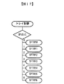
図17はトレイ制御の各サブルーチンを示す図である。
【0040】
排紙トレイ12の制御を行っているサブルーチンにおいて、SFUDJC(JOBカウンタ)にセットされているデータをチェックする。
SFUDJC(JOBカウンタ)=0の場合は図18に示す処理SFTRY0に進んでリターンし、SFUDJC(JOBカウンタ)=1の場合は図19に示す処理SFTRY1に進み、SFUDJC(JOBカウンタ)=2の場合は図20に示す処理SFTRY2に進み、SFUDJC(JOBカウンタ)=3の場合は図21に示す処理SFTRY3に進み、SFUDJC(JOBカウンタ)=4の場合は図22に示す処理SFTRY4に進み、SFUDJC(JOBカウンタ)=5の場合は図23に示す処理SFTRY5に進み、SFUDJC(JOBカウンタ)=6の場合は図24に示す処理SFTRY6に進む。
【0041】
図19はSFTRY1のサブルーチンのフローチャートである。
排紙トレイ12の上下駆動をしている上下モータ51を排紙トレイ12が下降する方向にオンさせる(S81)。S82のところでSFUDJCに“2”をセットすると共に、タイマUPJBT1を“0”にしてクリヤする。タイマUPJBT1は図示しないサブルーチンでカウントアップされる。
【0042】
図20はSFTRY2のサブルーチンのフローチャートである。
タイマUPJBT1が“150”を超えているかをチェックする(S91)。タイマUPJBT1が“150”を超えているときは(S91でYES)、上下モータ51をオフしてSFUDJCに“3”をセットする(S92)。S91でタイマUPJBT1が“150”を超えていないときは(S91でNO)、下限センサ34がオンしているかをチェックする(S93)。
下限センサ34がオンのときは(S93でYES)S92へ進み、オフのときは(S93ででNO)リターンする。
【0043】
図21はSFTRY3のサブルーチンのフローチャートである。
排紙トレイ12の上下駆動をしている上下モータ51を排紙トレイ12が上昇する方向にオンさせ(S101)、SFUDJCに“4”をセットすると共に、タイマUPJBT1を“0”にしてクリヤする(S102)。
【0044】
図22はSFTRY4のサブルーチンのフローチャートである。
紙面センサ33がオンしたか否かチェックしている(S111)。紙面センサ33がオンしている場合は(S111でYES)、上下モータ51をオフすると共に、SFUDJCに“4”をセットしてリターンする(S112)。
S111で紙面センサ33がオフしていた場合は(S111でNO)、タイマUPJBT1が“250”を超えているかをチェックする(S113)。タイマUPJBT1が“250”を超えていないときはNOへ行きリターンする。タイマUPJBT1が“250”を超えているときは(SでYES)、画像形成装置にジャム信号を送信するサブルーチンをコールしてリターンする。
【0045】
図23はSFTRY5のサブルーチンのフローチャートである。
排紙トレイ12の上下駆動をしている上下モータ51を排紙トレイ12が下降する方向にオンさせる(S121)、SFUDJCに“6”をセットすると共に、タイマUPJBT1を“0”にしてクリヤする(S122)。
【0046】
図24はSFTRY6のサブルーチンのフローチャートである。
紙面センサ33が(シフト)オフしたか否かをチェックしている(S131)。紙面センサ33がオフしている場合は(S131でYES)、上下モータ51をオフすると共に、SFUDJCに“0”をセットしてリターンする(S132)。S131で紙面センサ33がオンしていた場合は(S131でNO)、タイマUPJBT1が“100”を超えているかをチェックする(S133)。
タイマUPJBT1が“100”を超えていないときはNOへ行きリターンする。タイマUPJBT1が“100”を超えているときは(SでYES)、画像形成装置にジャム信号を送信するサブルーチンをコールしてリターンする。
【0047】
このような前記実施の形態にあっては、画像形成装置から排出される用紙をスティプルトレイ21に受け入れてその端部をスティプル処理するためのスティプルユニットと、スティプルユニットによりスティプル処理された用紙束をスティプルトレイ21外へ放出する放出ベルト10と、放出された用紙束を受け取りスタックする排紙トレイ12と、排紙トレイ12を上下方向に駆動する上下モータ51とを備えた用紙後処理装置において、排紙トレイ12面あるいは既に排紙トレイ12上にスタックされている用紙上面が、次に排紙されるスティプル済みの用紙束の先端が出たときには、垂れ下がり、下向きカールによる折り曲げスタック状態を回避するに足る上方位置にあるようにしたため、また、上方位置は排紙トレイ12に用紙を放出する放出口の下方近傍であるため、画像形成装置から排出されてくる用紙が画像面に対して下向きにカールしている用紙を一旦スティプルトレイにスタックして、用紙の端部にスティプル処理をした後、放出手段と排出手段により用紙束を排出しても先端が丸まって排出されることがないので、下方にカールした用紙が丸まった状態でスタックされるのを防止することができ、スタック性が良好になり、紙折れの不良を無くすことができる。
また、前記実施の形態にあっては、用紙の後端が排出されると、排紙トレイ12を所定距離下方に移動させ、移動後、所定時間経過すると、排紙トレイ12を上方位置に移動させるようにしたため、画像形成装置から排出されてくる用紙が画像面に対して下向きにカールしている用紙を一旦スティプルトレイ21にスタックして、用紙の端部にスティプル処理をし、放出手段と排出手段により用紙束を排出した後、排紙トレイ12を下げるので、確実に排紙トレイ12のエンドフェンスまで用紙束を良好にスタックできる。
また、前記実施の形態にあっては、スティプルされた用紙の枚数,サイズにより、用紙束受け入れ時の排紙トレイ12の位置を調整するため、用紙の枚数やサイズにより、排紙トレイ12の位置を若干調整することで、さらに信頼性を高めることができる。
【0048】
【発明の効果】
請求項1〜3記載の発明によれば、搬送されてくる用紙が画像面に対して下向きにカールしている用紙を一旦スティプルトレイにスタックして、用紙にスティプル処理をした後、排紙トレイに放出されるに際し、用紙の先端が丸まる前に受けることができるように、スティプルされた用紙束の綴じ枚数が所定の枚数より多い場合や用紙束の用紙サイズが所定のサイズより大きい場合には、前記所定の上方位置を更に上方の位置へ調整するすることで、用紙の状態に応じ決め細かい対応としてさらに信頼性を高めることができる。
請求項4記載の発明によれば、請求項1ないし3記載の発明による作用効果を奏する画像形成装置を提供することができる。
【図面の簡単な説明】
【図1】本発明の実施の形態に係る用紙後処理装置全体の構成図である。
【図2】ジョガーフェンスと戻しローラの駆動機構を示す斜視図である。
【図3】後端フェンス部近傍の第1の例を示す拡大構成図である。
【図4】スティプル装置を中心とした斜視図である。
【図5】綴じ後の用紙束を放出ベルトにより放出する様子を示す透視斜視図である。
【図6】本発明の実施の形態に係る用紙後処理装置の電装系のブロック図である。
【図7】排紙トレイ上下機構を示す透視斜視図である。
【図8】排紙トレイにスタックされた用紙束の状態を示す図である。
【図9】トレイ下降チェックのフローチャートである。
【図10】排紙処理の各サブルーチンを示す図である。
【図11】図10のサブルーチン(EXIT0)のフローチャートである。
【図12】図10のサブルーチン(EXIT1)のフローチャートである。
【図13】図10のサブルーチン(EXIT2)のフローチャートである。
【図14】図10のサブルーチン(EXIT3)のフローチャートである。
【図15】図10のサブルーチン(EXIT4)のフローチャートである。
【図16】図10のサブルーチン(EXIT5)のフローチャートである。
【図17】トレイ制御の各サブルーチンを示す図である。
【図18】図17のサブルーチン(SFTRY0)のフローチャートである。
【図19】図17のサブルーチン(SFTRY1)のフローチャートである。
【図20】図17のサブルーチン(SFTRY2)のフローチャートである。
【図21】図17のサブルーチン(SFTRY3)のフローチャートである。
【図22】図17のサブルーチン(SFTRY4)のフローチャートである。
【図23】図17のサブルーチン(SFTRY5)のフローチャートである。
【図24】図17のサブルーチン(SFTRY6)のフローチャートである。
【符号の説明】
2 上搬送ローラ
3 排出ローラ
4 下搬送ローラ
5 戻しローラ
6 紙送りローラ
8 分岐爪
9 ジョガーフェンス
10 放出ベルト
10a 放出爪
11 スティプル装置(スティプルユニット)
12 排紙トレイ
21 スティプルトレイ
51 上下モータ[0001]
BACKGROUND OF THE INVENTION
The present invention relates to a sheet post-processing apparatus connected to a sheet discharge unit of an image forming apparatus such as a copying machine, a printer, or a facsimile machine.And image forming apparatus including the sheet post-processing apparatusAbout.
[0002]
[Prior art]
A stipple unit for receiving paper discharged from the image forming apparatus into a stipple tray and subjecting the end portion thereof to a stipple process; There has been proposed a paper post-processing apparatus including a paper discharge tray that receives and stacks the discharged paper bundle and a driving unit that drives the paper discharge tray in the vertical direction.
In such a sheet post-processing apparatus, when the leading end of the stapled sheet bundle (the end opposite to the stapled end) is curled downward, the sheet is discharged to the discharge tray. The curled portion is bent or rounded and stacked on the sheet discharge tray surface.
Even when the paper size is large, the paper is thin, or even when the number of stapled papers is large, if there is a distance between the paper output unit and the paper output tray surface, it may also hang downward. It becomes the same state as.
[0003]
[Problems to be solved by the invention]
As described above, in the conventional paper post-processing apparatus, when the paper is curled downward, or depending on the size, type, and number of papers, the paper is discharged in a state where some of the papers are curled from the bottom. There is a problem that a stack of sheets is folded because the sheets are stacked on the tray. In addition, it is unnecessarily bulky in the height direction, and a predetermined number of copies cannot be stacked, resulting in a problem of poor stack efficiency.
[0004]
The present inventionSectionThe title is a paper post-processing device that can avoid stack failures and paper breaks in the stack of paper ejected onto the paper ejection tray.And image forming apparatusIs to provide.
[0005]
[Means for Solving the Problems]
UpLessonThe title isBe transportedPaperReceivedStocking, Multiple paperStipple processingRuHippurmeansWhen,TheTipped paper bundleCan move up and downOutput trayAndIn the paper post-processing device provided,When the stapled sheet bundle is discharged onto the paper discharge tray, the control means includes a control unit that temporarily raises the paper discharge tray to a predetermined upper position. If the number is larger than the predetermined number, the predetermined upper position is adjusted to a further upper position.This is solved by the first means.
An object of the present invention is to provide a stipple in a sheet post-processing apparatus including a stipple unit that receives a conveyed sheet and stipples a plurality of sheets, and a vertically movable discharge tray that stacks a bundle of stipulated sheets. A control unit that temporarily raises the discharge tray to a predetermined upper position when the discharged sheet bundle is discharged onto the discharge tray, and the control unit has a predetermined paper size of the stapled bundle of sheets. If the size is larger than the predetermined size, the second means for adjusting the predetermined upper position to a further upper position is solved.
In the first or second means, the above problem is solved by a third means in which the upper position is in the vicinity of the lower part of the discharge port for discharging the paper to the paper discharge tray.
The above problem is solved by the fourth means including the sheet post-processing apparatus of the first to third means.
[0006]
DETAILED DESCRIPTION OF THE INVENTION
Hereinafter, embodiments of the present invention will be described with reference to the drawings.
[0007]
FIG. 1 is a configuration diagram of the entire sheet post-processing apparatus according to an embodiment of the present invention, FIG. 2 is a perspective view showing a driving mechanism for a jogger fence and a return roller, and FIG. 3 is a first example near the rear end fence portion. FIG. 4 is a perspective view centering on the staple device, FIG. 5 is a perspective view showing a state in which the bundle of sheets after binding is discharged by the discharge belt, and FIG. 6 is a sheet according to the embodiment of the present invention. It is a block diagram of the electrical equipment system of a post-processing apparatus.
[0008]
In FIG. 1, a
The transport path in the direction of the
The
The
As shown in FIG. 2, the
[0009]
The
As shown in FIG. 4, the
By the way, even if the
Further, as shown in FIG. 5, the rear end of the sheet bundle bound by the
[0010]
Here, an electrical system of the sheet post-processing apparatus according to the embodiment of the present invention will be described with reference to FIG.
As shown in FIG. 6, signals from the switches and sensors in the sheet post-processing apparatus are input to the
[0011]
Next, in the above embodiment, the operation when the non-stipple mode in which stippling is not performed is selected will be described.
The copied paper is received by the
At this time, the
In the sort and stack modes, the
[0012]
Next, a case where the stipple mode is selected will be described.
When the stipple mode is selected, as shown in FIG. 2, the
The
The
After the
[0013]
Thereafter, the
When the binding process is completed, the
For example, when the number of sheets to be bound is less than the set number or smaller than the set size, the trailing edge of the sheet bundle is hooked and conveyed by the
Then, the
If the number of sheets to be bound is larger than the set number or larger than the set size, the
The above series of operations is repeated until the last job.
[0014]
FIG. 7 is a perspective view showing the discharge tray up / down mechanism.
As shown in FIG. 7, the
The home position of the
[0015]
FIG. 8 is a diagram illustrating a state of the sheet bundle stacked on the sheet discharge tray.
As described above, when the surface of the
[0016]
In the present invention, when stacking a sheet bundle on the
As described above, the
[0017]
FIG. 9 is a flowchart of the tray lowering check.
More specifically, it is a flowchart in which the state of the
[0018]
It is checked whether TRYUPF (tray up flag) is set to “1” (S1). If “1” (YES in S1), S7 is processed. In S7, “1” is set in SFUDJC and the process returns. When it is not “1” (NO in S1), S2 is processed.
In S2, it is checked whether the
In S3, the state of the
[0019]
In S4, it is checked whether TRYCKT (tray check timer) is larger than “5”. When TRYCKT (tray check timer) is smaller than “5” (NO in S4), the process returns. If TRYCKT (tray check timer) is greater than “5” (YES in S4), “5” is set in SFUDJC and the process returns.
The TRYCKT (tray check timer) delays the timing so that the
[0020]
FIG. 10 is a diagram illustrating each subroutine of the paper discharge process.
More specifically, this is a subroutine for controlling the
[0021]
The data set in EXJOBC (JOB counter) is checked. If EXJOBC (JOB counter) = 0, the process proceeds to the process EXIT0 shown in FIG. 11 and returns. If EXJOBC (JOB counter) = 1, The process proceeds to the process EXIT1 shown in FIG. 12. If EXJOBC (JOB counter) = 2, the process proceeds to the process EXIT2 shown in FIG. If JOB counter) = 4, the process proceeds to process EXIT4 shown in FIG. 15. If EXJOBC (JOB counter) = 5, the process proceeds to process EXIT5 shown in FIG.
[0022]
Next, the EXIT1 subroutine will be described.
FIG. 12 is a flowchart of the EXIT1 subroutine.
The rotation data of the
[0023]
Next, the EXIT2 subroutine will be described.
FIG. 13 is a flowchart of the EXIT2 subroutine.
[0024]
It is checked whether the
If the
[0025]
Next, the EXIT3 subroutine will be described.
FIG. 14 is a flowchart of the EXIT3 subroutine.
[0026]
It is checked whether the paper size is A3 or B4 (S31). In the case of A3 and B4 (YES in S31), it is checked whether or not the value of the sheet number counter STRYCU for counting the number of sheets stacked on the
Each time a sheet is discharged to the
[0027]
If the timer TIM2CU does not exceed “50” (NO in S33), the process returns. If the timer TIM2CU exceeds “50” (YES in S33), the rotation data “50” of the
When the value of the sheet number counter STRYCU is not "16" or more in S32, it is checked whether the timer TIM2CU has exceeded "40" (S36), and if not (NO in S36), the process returns. If it exceeds (YES in S36), go to S34.
[0028]
If NO in S31, it is checked in S37 whether the size is A4 vertical or B5 vertical. In the case of A4 vertical size and B5 vertical size (YES in S37), it is checked whether or not the value of the sheet number counter STRYCU is “25” or more (S38), and the value of the sheet number counter STRYCU is larger than “25”. If so (YES in S38), it is checked whether the timer TIM2CU exceeds "35" (S39).
If the timer TIM2CU does not exceed “35” (NO in S39), the process returns. When the timer TIM2CU exceeds “35” (YES in S39), the process goes to S34.
[0029]
If NO in S38, it is checked in S40 whether the timer TIM2CU exceeds “30”. When the timer TIM2CU does not exceed “30” (NO in S40), the process returns. When the timer TIM2CU exceeds “30” (YES in S40), the process goes to S34.
[0030]
If NO in S37, it is checked in S41 whether the timer TIM2CU exceeds “35”. If the timer TIM2CU does not exceed “35” (NO in S41), the process returns. When the timer TIM2CU exceeds “35” (YES in S41), the process goes to S34.
[0031]
As described above, the numbers “16” and “25” are entered at S32 and S38 for determining the contents of the sheet number counter STRYCU. These numbers are certain predetermined values. The numerical value where the numerical value of the timer TIM2CU is determined is also a predetermined value.
[0032]
Next, the EXIT4 subroutine will be described.
FIG. 15 is a flowchart of the EXIT4 subroutine.
[0033]
It is checked whether or not the
In the case of A3 and B4 (YES in S52), it is checked whether or not the value of the sheet number counter STRYCU for counting the number of sheets stacked on the
Next, in S55, “5” is set to EXJOBC (JOB counter), timer TIM1CU is reset to “0”, and the process returns. If the value of the sheet number counter STRYCU is not less than “5” in S53 (YES in S53), the process proceeds to S55.
[0034]
If NO in S52, it is checked in S56 whether the size is A4 vertical or B5 vertical. If the size is A4 portrait or B5 portrait (YES in S52), it is checked whether the value of the sheet number counter STRYCU is less than "10" (S57). If the value of the sheet number counter STRYCU is less than "10" (NO in S57) Proceed to S54. When the value of the sheet number counter STRYCU is not less than “10” (YES in S57), the process proceeds to S55.
[0035]
If NO in S56, it is checked in S58 whether the size is A4 horizontal or B5 horizontal. In the case of A4 horizontal size and B5 horizontal size (YES in S58), it is checked whether or not the value of the sheet number counter STRYCU is less than “10” (S59), and the value of the sheet number counter STRYCU is less than “10”. (YES in S59), the process proceeds to S54. When the value of the sheet number counter STRYCU is larger than “10” (NO in S59), the process proceeds to S55.
When NO in S58 (when A4 portrait or B5 portrait size is not), it is checked whether or not the value of the sheet number counter STRYCU is less than “15” (S60), and the value of the sheet number counter STRYCU is less than “15”. Advances to S54. If the value of the sheet number counter STRYCU is not less than “15”, the process proceeds to S55.
[0036]
If the
[0037]
Next, the EXIT5 subroutine will be described.
FIG. 16 is a flowchart of the EXIT5 subroutine.
[0038]
It is checked whether the timer TIM1CU exceeds “200” (S71). If the timer TIM1CU does not exceed “200” (NO in S71), the process returns. If the timer TIM1CU exceeds “200” (YES in S71), the
[0039]
FIG. 17 is a diagram showing each subroutine of tray control.
[0040]
In the subroutine for controlling the
When SFUDJC (JOB counter) = 0, the process proceeds to the process SFTRY0 shown in FIG. 18 and returns. When SFUDJC (JOB counter) = 1, the process proceeds to the process SFTRY1 shown in FIG. 20 proceeds to the process SFTRY2 shown in FIG. 20, and if SUDJC (JOB counter) = 3, the process proceeds to the process SFTRY3 shown in FIG. If (JOB counter) = 5, the process proceeds to the process SFTRY5 shown in FIG. 23. If SFUDJC (JOB counter) = 6, the process proceeds to the process SFTRY6 shown in FIG.
[0041]
FIG. 19 is a flowchart of the SFTRY1 subroutine.
The
[0042]
FIG. 20 is a flowchart of the SFTRY2 subroutine.
It is checked whether the timer UPJBT1 exceeds “150” (S91). If the timer UPJBT1 exceeds “150” (YES in S91), the upper and
When the
[0043]
FIG. 21 is a flowchart of the SFTRY3 subroutine.
The
[0044]
FIG. 22 is a flowchart of the SFTRY4 subroutine.
It is checked whether or not the
If the
[0045]
FIG. 23 is a flowchart of SFTRY5 subroutine.
The
[0046]
FIG. 24 is a flowchart of the SFTRY6 subroutine.
It is checked whether or not the
If the timer UPJBT1 does not exceed “100”, go to NO and return. When the timer UPJBT1 exceeds “100” (YES in S), a subroutine for transmitting a jam signal to the image forming apparatus is called and the process returns.
[0047]
In such an embodiment, the paper discharged from the image forming apparatus is received in the
In the embodiment, when the trailing edge of the sheet is discharged, the
In the embodiment, the position of the
[0048]
【The invention's effect】
Claim1-3According to the described invention,When the paper that is being conveyed is curled downward with respect to the image surface, the paper is once stacked on the stipple tray, then stipulated on the paper, and then discharged to the paper output tray. As can be received before, when the number of stapled bundles of sheets is greater than a predetermined number or when the sheet size of the sheet bundle is larger than a predetermined size, the predetermined upper position is set to a further upper position. Adjust toby doing,As a detailed response that depends on the paper conditionFurthermore, reliability can be improved.
According to the invention described in
[Brief description of the drawings]
FIG. 1 is a configuration diagram of an entire sheet post-processing apparatus according to an embodiment of the present invention.
FIG. 2 is a perspective view showing a driving mechanism for a jogger fence and a return roller.
FIG. 3 is an enlarged configuration diagram showing a first example in the vicinity of a rear end fence portion.
FIG. 4 is a perspective view centering on a stipple device.
FIG. 5 is a perspective view illustrating a state in which a bundle of sheets after binding is discharged by a discharge belt.
FIG. 6 is a block diagram of an electrical system of the sheet post-processing apparatus according to the embodiment of the present invention.
FIG. 7 is a perspective view illustrating a discharge tray up / down mechanism.
FIG. 8 is a diagram illustrating a state of a sheet bundle stacked on a sheet discharge tray.
FIG. 9 is a flowchart of a tray lowering check.
FIG. 10 is a diagram illustrating subroutines for paper discharge processing.
11 is a flowchart of a subroutine (EXIT0) of FIG.
12 is a flowchart of a subroutine (EXIT1) of FIG.
13 is a flowchart of the subroutine (EXIT2) of FIG.
14 is a flowchart of a subroutine (EXIT3) of FIG.
FIG. 15 is a flowchart of a subroutine (EXIT4) of FIG.
16 is a flowchart of a subroutine (EXIT5) in FIG.
FIG. 17 is a diagram illustrating each subroutine of tray control.
FIG. 18 is a flowchart of the subroutine (SFTRY0) in FIG.
FIG. 19 is a flowchart of a subroutine (SFTRY1) in FIG. 17;
20 is a flowchart of a subroutine (SFTRY2) in FIG.
FIG. 21 is a flowchart of a subroutine (SFTRY3) in FIG. 17;
FIG. 22 is a flowchart of the subroutine (SFTRY4) of FIG.
FIG. 23 is a flowchart of a subroutine (SFTRY5) in FIG. 17;
24 is a flowchart of a subroutine (SFTRY6) in FIG.
[Explanation of symbols]
2 Upper transport roller
3 Discharge roller
4 Lower transport roller
5 Return roller
6 Paper feed roller
8 branch claws
9 Jogger fence
10 Release belt
10a Release claw
11 Stipple device (stipple unit)
12 Output tray
21 Stipple tray
51 Vertical motor
Claims (4)
スティプル処理された用紙束を積載する上下移動可能な排紙トレイとを備えた用紙後処理装置において、
スティプルされた用紙束を前記排紙トレイ上に放出するに際し、一時的に前記排紙トレイを所定の上方位置へ上昇させる制御手段を備え、
前記制御手段は、スティプルされた用紙束の綴じ枚数が所定の枚数より多い場合には、前記所定の上方位置を更に上方の位置へ調整することを特徴とする用紙後処理装置。Put accept the sheet conveyed, and stearyl Ipuru means you stippling a plurality of sheets,
In the sheet post-processing apparatus having a paper discharge tray vertically movable for loading the scan Tipuru treated sheet bundle,
Control means for temporarily raising the discharge tray to a predetermined upper position when discharging the stapled bundle of sheets onto the discharge tray;
The control means adjusts the predetermined upper position to a further upper position when the number of stapled bundles of stapled paper bundles is larger than a predetermined number .
スティプル処理された用紙束を積載する上下移動可能な排紙トレイとを備えた用紙後処理装置において、
スティプルされた用紙束を前記排紙トレイ上に放出するに際し、一時的に前記排紙トレイを所定の上方位置へ上昇させる制御手段を備え、
前記制御手段は、スティプルされた用紙束の用紙サイズが所定のサイズより大きい場合には、前記所定の上方位置を更に上方の位置へ調整することを特徴とする用紙後処理装置。 A stipple means for receiving the conveyed paper and stipling a plurality of paper;
In a paper post-processing apparatus having a vertically movable paper discharge tray for stacking a stapled paper bundle,
Control means for temporarily raising the discharge tray to a predetermined upper position when discharging the stapled bundle of sheets onto the discharge tray;
The control unit adjusts the predetermined upper position to a further upper position when the paper size of the stapled sheet bundle is larger than a predetermined size .
Priority Applications (1)
| Application Number | Priority Date | Filing Date | Title |
|---|---|---|---|
| JP10483997A JP3614274B2 (en) | 1997-04-22 | 1997-04-22 | Paper post-processing apparatus and image forming apparatus |
Applications Claiming Priority (1)
| Application Number | Priority Date | Filing Date | Title |
|---|---|---|---|
| JP10483997A JP3614274B2 (en) | 1997-04-22 | 1997-04-22 | Paper post-processing apparatus and image forming apparatus |
Publications (2)
| Publication Number | Publication Date |
|---|---|
| JPH10291723A JPH10291723A (en) | 1998-11-04 |
| JP3614274B2 true JP3614274B2 (en) | 2005-01-26 |
Family
ID=14391527
Family Applications (1)
| Application Number | Title | Priority Date | Filing Date |
|---|---|---|---|
| JP10483997A Expired - Fee Related JP3614274B2 (en) | 1997-04-22 | 1997-04-22 | Paper post-processing apparatus and image forming apparatus |
Country Status (1)
| Country | Link |
|---|---|
| JP (1) | JP3614274B2 (en) |
Families Citing this family (4)
| Publication number | Priority date | Publication date | Assignee | Title |
|---|---|---|---|---|
| JP2001270642A (en) * | 2000-03-28 | 2001-10-02 | Ricoh Co Ltd | Fixing device and image forming device |
| US7661666B2 (en) | 2005-09-21 | 2010-02-16 | Toshiba Tec Kabushiki Kaisha | Sheet processing apparatus and sheet processing method |
| JP4511458B2 (en) * | 2005-12-29 | 2010-07-28 | 東芝テック株式会社 | Paper post-processing device |
| JP6080012B2 (en) * | 2013-07-16 | 2017-02-15 | 富士ゼロックス株式会社 | Post-processing apparatus, image forming apparatus, and program |
-
1997
- 1997-04-22 JP JP10483997A patent/JP3614274B2/en not_active Expired - Fee Related
Also Published As
| Publication number | Publication date |
|---|---|
| JPH10291723A (en) | 1998-11-04 |
Similar Documents
| Publication | Publication Date | Title |
|---|---|---|
| JP3466376B2 (en) | Paper post-processing equipment | |
| JP3621565B2 (en) | Sheet alignment apparatus and image forming apparatus | |
| JPH11165935A (en) | Paper exhaust tray and paper post-treatment device | |
| JP3614274B2 (en) | Paper post-processing apparatus and image forming apparatus | |
| JP3655407B2 (en) | Paper post-processing device | |
| JP3732598B2 (en) | Post-processing equipment | |
| JP3483109B2 (en) | Paper loading device | |
| JP3655428B2 (en) | Paper post-processing apparatus and image forming apparatus | |
| JP2533095B2 (en) | Sheet aftertreatment device | |
| JP3592869B2 (en) | Post-processing device | |
| JP4217314B2 (en) | Sheet processing apparatus and image forming apparatus having the same | |
| JP3262665B2 (en) | Recording paper loading device | |
| JP3617926B2 (en) | Paper post-processing apparatus and image forming apparatus | |
| JP3228834B2 (en) | Recording paper processing equipment | |
| JP3655431B2 (en) | Paper post-processing apparatus and image forming apparatus | |
| JP3434365B2 (en) | Paper post-processing equipment | |
| JP3658509B2 (en) | Paper loading device | |
| JP3441897B2 (en) | Paper post-processing equipment | |
| JP3302305B2 (en) | Sheet processing apparatus and image forming apparatus having the same | |
| JP3850590B2 (en) | Paper discharge device and image forming apparatus | |
| JPH10324445A (en) | Paper sheet post-processing device | |
| JP2000072315A (en) | Paper aftertreatment device | |
| JPH09240909A (en) | Sheet postprocessing device | |
| JP4734099B2 (en) | Sheet processing apparatus and image forming apparatus | |
| JPH1111774A (en) | Sheet stacking device |
Legal Events
| Date | Code | Title | Description |
|---|---|---|---|
| A977 | Report on retrieval |
Free format text: JAPANESE INTERMEDIATE CODE: A971007 Effective date: 20040706 |
|
| A131 | Notification of reasons for refusal |
Free format text: JAPANESE INTERMEDIATE CODE: A131 Effective date: 20040720 |
|
| A521 | Written amendment |
Free format text: JAPANESE INTERMEDIATE CODE: A523 Effective date: 20040917 |
|
| TRDD | Decision of grant or rejection written | ||
| A01 | Written decision to grant a patent or to grant a registration (utility model) |
Free format text: JAPANESE INTERMEDIATE CODE: A01 Effective date: 20041019 |
|
| A61 | First payment of annual fees (during grant procedure) |
Free format text: JAPANESE INTERMEDIATE CODE: A61 Effective date: 20041026 |
|
| FPAY | Renewal fee payment (event date is renewal date of database) |
Free format text: PAYMENT UNTIL: 20071112 Year of fee payment: 3 |
|
| FPAY | Renewal fee payment (event date is renewal date of database) |
Free format text: PAYMENT UNTIL: 20081112 Year of fee payment: 4 |
|
| FPAY | Renewal fee payment (event date is renewal date of database) |
Free format text: PAYMENT UNTIL: 20081112 Year of fee payment: 4 |
|
| FPAY | Renewal fee payment (event date is renewal date of database) |
Free format text: PAYMENT UNTIL: 20091112 Year of fee payment: 5 |
|
| FPAY | Renewal fee payment (event date is renewal date of database) |
Free format text: PAYMENT UNTIL: 20101112 Year of fee payment: 6 |
|
| FPAY | Renewal fee payment (event date is renewal date of database) |
Free format text: PAYMENT UNTIL: 20111112 Year of fee payment: 7 |
|
| FPAY | Renewal fee payment (event date is renewal date of database) |
Free format text: PAYMENT UNTIL: 20111112 Year of fee payment: 7 |
|
| FPAY | Renewal fee payment (event date is renewal date of database) |
Free format text: PAYMENT UNTIL: 20121112 Year of fee payment: 8 |
|
| FPAY | Renewal fee payment (event date is renewal date of database) |
Free format text: PAYMENT UNTIL: 20131112 Year of fee payment: 9 |
|
| LAPS | Cancellation because of no payment of annual fees |