JP3594346B2 - Method for manufacturing BiCMOS device - Google Patents
Method for manufacturing BiCMOS device Download PDFInfo
- Publication number
- JP3594346B2 JP3594346B2 JP33322294A JP33322294A JP3594346B2 JP 3594346 B2 JP3594346 B2 JP 3594346B2 JP 33322294 A JP33322294 A JP 33322294A JP 33322294 A JP33322294 A JP 33322294A JP 3594346 B2 JP3594346 B2 JP 3594346B2
- Authority
- JP
- Japan
- Prior art keywords
- layer
- region
- forming
- source
- insulating layer
- Prior art date
- Legal status (The legal status is an assumption and is not a legal conclusion. Google has not performed a legal analysis and makes no representation as to the accuracy of the status listed.)
- Expired - Fee Related
Links
- 238000000034 method Methods 0.000 title claims description 32
- 238000004519 manufacturing process Methods 0.000 title claims description 17
- 239000004065 semiconductor Substances 0.000 claims description 21
- WQJQOUPTWCFRMM-UHFFFAOYSA-N tungsten disilicide Chemical compound [Si]#[W]#[Si] WQJQOUPTWCFRMM-UHFFFAOYSA-N 0.000 claims description 17
- 229910021342 tungsten silicide Inorganic materials 0.000 claims description 17
- 238000005530 etching Methods 0.000 claims description 14
- 238000000151 deposition Methods 0.000 claims description 9
- 239000011159 matrix material Substances 0.000 claims description 2
- 229910021420 polycrystalline silicon Inorganic materials 0.000 description 24
- 229920005591 polysilicon Polymers 0.000 description 10
- VYPSYNLAJGMNEJ-UHFFFAOYSA-N Silicium dioxide Chemical compound O=[Si]=O VYPSYNLAJGMNEJ-UHFFFAOYSA-N 0.000 description 8
- 239000003870 refractory metal Substances 0.000 description 8
- 125000006850 spacer group Chemical group 0.000 description 8
- IJGRMHOSHXDMSA-UHFFFAOYSA-N Atomic nitrogen Chemical compound N#N IJGRMHOSHXDMSA-UHFFFAOYSA-N 0.000 description 6
- BOTDANWDWHJENH-UHFFFAOYSA-N Tetraethyl orthosilicate Chemical compound CCO[Si](OCC)(OCC)OCC BOTDANWDWHJENH-UHFFFAOYSA-N 0.000 description 5
- 238000000137 annealing Methods 0.000 description 5
- 229910052751 metal Inorganic materials 0.000 description 4
- 239000002184 metal Substances 0.000 description 4
- 230000003647 oxidation Effects 0.000 description 4
- 238000007254 oxidation reaction Methods 0.000 description 4
- 229910021332 silicide Inorganic materials 0.000 description 4
- FVBUAEGBCNSCDD-UHFFFAOYSA-N silicide(4-) Chemical compound [Si-4] FVBUAEGBCNSCDD-UHFFFAOYSA-N 0.000 description 4
- 235000012239 silicon dioxide Nutrition 0.000 description 4
- 239000000377 silicon dioxide Substances 0.000 description 4
- 239000000758 substrate Substances 0.000 description 4
- XUIMIQQOPSSXEZ-UHFFFAOYSA-N Silicon Chemical compound [Si] XUIMIQQOPSSXEZ-UHFFFAOYSA-N 0.000 description 3
- 239000007943 implant Substances 0.000 description 3
- 238000002955 isolation Methods 0.000 description 3
- 229910052757 nitrogen Inorganic materials 0.000 description 3
- 229910052710 silicon Inorganic materials 0.000 description 3
- 239000010703 silicon Substances 0.000 description 3
- 229910008484 TiSi Inorganic materials 0.000 description 2
- 230000015572 biosynthetic process Effects 0.000 description 2
- 239000002019 doping agent Substances 0.000 description 2
- 238000011065 in-situ storage Methods 0.000 description 2
- 230000010354 integration Effects 0.000 description 2
- 238000005468 ion implantation Methods 0.000 description 2
- 238000012986 modification Methods 0.000 description 2
- 230000004048 modification Effects 0.000 description 2
- 150000004767 nitrides Chemical class 0.000 description 2
- ZOXJGFHDIHLPTG-UHFFFAOYSA-N Boron Chemical compound [B] ZOXJGFHDIHLPTG-UHFFFAOYSA-N 0.000 description 1
- 229910052581 Si3N4 Inorganic materials 0.000 description 1
- 229910052796 boron Inorganic materials 0.000 description 1
- 230000000295 complement effect Effects 0.000 description 1
- 239000004020 conductor Substances 0.000 description 1
- 238000007796 conventional method Methods 0.000 description 1
- 230000008021 deposition Effects 0.000 description 1
- 238000005137 deposition process Methods 0.000 description 1
- 230000009977 dual effect Effects 0.000 description 1
- 230000000694 effects Effects 0.000 description 1
- 230000004927 fusion Effects 0.000 description 1
- 239000007789 gas Substances 0.000 description 1
- 238000002513 implantation Methods 0.000 description 1
- 239000012535 impurity Substances 0.000 description 1
- 238000012886 linear function Methods 0.000 description 1
- 238000004518 low pressure chemical vapour deposition Methods 0.000 description 1
- 230000008018 melting Effects 0.000 description 1
- 238000002844 melting Methods 0.000 description 1
- 238000001465 metallisation Methods 0.000 description 1
- 230000001590 oxidative effect Effects 0.000 description 1
- RLOWWWKZYUNIDI-UHFFFAOYSA-N phosphinic chloride Chemical compound ClP=O RLOWWWKZYUNIDI-UHFFFAOYSA-N 0.000 description 1
- HQVNEWCFYHHQES-UHFFFAOYSA-N silicon nitride Chemical compound N12[Si]34N5[Si]62N3[Si]51N64 HQVNEWCFYHHQES-UHFFFAOYSA-N 0.000 description 1
Images


Classifications
-
- H—ELECTRICITY
- H01—ELECTRIC ELEMENTS
- H01L—SEMICONDUCTOR DEVICES NOT COVERED BY CLASS H10
- H01L27/00—Devices consisting of a plurality of semiconductor or other solid-state components formed in or on a common substrate
- H01L27/02—Devices consisting of a plurality of semiconductor or other solid-state components formed in or on a common substrate including semiconductor components specially adapted for rectifying, oscillating, amplifying or switching and having potential barriers; including integrated passive circuit elements having potential barriers
- H01L27/04—Devices consisting of a plurality of semiconductor or other solid-state components formed in or on a common substrate including semiconductor components specially adapted for rectifying, oscillating, amplifying or switching and having potential barriers; including integrated passive circuit elements having potential barriers the substrate being a semiconductor body
-
- H—ELECTRICITY
- H01—ELECTRIC ELEMENTS
- H01L—SEMICONDUCTOR DEVICES NOT COVERED BY CLASS H10
- H01L21/00—Processes or apparatus adapted for the manufacture or treatment of semiconductor or solid state devices or of parts thereof
- H01L21/70—Manufacture or treatment of devices consisting of a plurality of solid state components formed in or on a common substrate or of parts thereof; Manufacture of integrated circuit devices or of parts thereof
- H01L21/77—Manufacture or treatment of devices consisting of a plurality of solid state components or integrated circuits formed in, or on, a common substrate
- H01L21/78—Manufacture or treatment of devices consisting of a plurality of solid state components or integrated circuits formed in, or on, a common substrate with subsequent division of the substrate into plural individual devices
- H01L21/82—Manufacture or treatment of devices consisting of a plurality of solid state components or integrated circuits formed in, or on, a common substrate with subsequent division of the substrate into plural individual devices to produce devices, e.g. integrated circuits, each consisting of a plurality of components
- H01L21/822—Manufacture or treatment of devices consisting of a plurality of solid state components or integrated circuits formed in, or on, a common substrate with subsequent division of the substrate into plural individual devices to produce devices, e.g. integrated circuits, each consisting of a plurality of components the substrate being a semiconductor, using silicon technology
- H01L21/8248—Combination of bipolar and field-effect technology
- H01L21/8249—Bipolar and MOS technology
-
- H—ELECTRICITY
- H01—ELECTRIC ELEMENTS
- H01L—SEMICONDUCTOR DEVICES NOT COVERED BY CLASS H10
- H01L27/00—Devices consisting of a plurality of semiconductor or other solid-state components formed in or on a common substrate
- H01L27/02—Devices consisting of a plurality of semiconductor or other solid-state components formed in or on a common substrate including semiconductor components specially adapted for rectifying, oscillating, amplifying or switching and having potential barriers; including integrated passive circuit elements having potential barriers
- H01L27/04—Devices consisting of a plurality of semiconductor or other solid-state components formed in or on a common substrate including semiconductor components specially adapted for rectifying, oscillating, amplifying or switching and having potential barriers; including integrated passive circuit elements having potential barriers the substrate being a semiconductor body
- H01L27/06—Devices consisting of a plurality of semiconductor or other solid-state components formed in or on a common substrate including semiconductor components specially adapted for rectifying, oscillating, amplifying or switching and having potential barriers; including integrated passive circuit elements having potential barriers the substrate being a semiconductor body including a plurality of individual components in a non-repetitive configuration
- H01L27/07—Devices consisting of a plurality of semiconductor or other solid-state components formed in or on a common substrate including semiconductor components specially adapted for rectifying, oscillating, amplifying or switching and having potential barriers; including integrated passive circuit elements having potential barriers the substrate being a semiconductor body including a plurality of individual components in a non-repetitive configuration the components having an active region in common
- H01L27/0705—Devices consisting of a plurality of semiconductor or other solid-state components formed in or on a common substrate including semiconductor components specially adapted for rectifying, oscillating, amplifying or switching and having potential barriers; including integrated passive circuit elements having potential barriers the substrate being a semiconductor body including a plurality of individual components in a non-repetitive configuration the components having an active region in common comprising components of the field effect type
- H01L27/0711—Devices consisting of a plurality of semiconductor or other solid-state components formed in or on a common substrate including semiconductor components specially adapted for rectifying, oscillating, amplifying or switching and having potential barriers; including integrated passive circuit elements having potential barriers the substrate being a semiconductor body including a plurality of individual components in a non-repetitive configuration the components having an active region in common comprising components of the field effect type in combination with bipolar transistors and diodes, or capacitors, or resistors
- H01L27/0716—Devices consisting of a plurality of semiconductor or other solid-state components formed in or on a common substrate including semiconductor components specially adapted for rectifying, oscillating, amplifying or switching and having potential barriers; including integrated passive circuit elements having potential barriers the substrate being a semiconductor body including a plurality of individual components in a non-repetitive configuration the components having an active region in common comprising components of the field effect type in combination with bipolar transistors and diodes, or capacitors, or resistors in combination with vertical bipolar transistors and diodes, or capacitors, or resistors
-
- H—ELECTRICITY
- H01—ELECTRIC ELEMENTS
- H01L—SEMICONDUCTOR DEVICES NOT COVERED BY CLASS H10
- H01L2924/00—Indexing scheme for arrangements or methods for connecting or disconnecting semiconductor or solid-state bodies as covered by H01L24/00
- H01L2924/0001—Technical content checked by a classifier
- H01L2924/0002—Not covered by any one of groups H01L24/00, H01L24/00 and H01L2224/00
-
- Y—GENERAL TAGGING OF NEW TECHNOLOGICAL DEVELOPMENTS; GENERAL TAGGING OF CROSS-SECTIONAL TECHNOLOGIES SPANNING OVER SEVERAL SECTIONS OF THE IPC; TECHNICAL SUBJECTS COVERED BY FORMER USPC CROSS-REFERENCE ART COLLECTIONS [XRACs] AND DIGESTS
- Y10—TECHNICAL SUBJECTS COVERED BY FORMER USPC
- Y10S—TECHNICAL SUBJECTS COVERED BY FORMER USPC CROSS-REFERENCE ART COLLECTIONS [XRACs] AND DIGESTS
- Y10S148/00—Metal treatment
- Y10S148/009—Bi-MOS
Landscapes
- Engineering & Computer Science (AREA)
- Power Engineering (AREA)
- Physics & Mathematics (AREA)
- Condensed Matter Physics & Semiconductors (AREA)
- General Physics & Mathematics (AREA)
- Computer Hardware Design (AREA)
- Microelectronics & Electronic Packaging (AREA)
- Manufacturing & Machinery (AREA)
- Metal-Oxide And Bipolar Metal-Oxide Semiconductor Integrated Circuits (AREA)
- Bipolar Transistors (AREA)
- Bipolar Integrated Circuits (AREA)
Description
【0001】
【産業上の利用分野】
本発明は一般的に半導体処理に関するものであり、更に詳細にはBiCMOSプロセスに関する。
【0002】
【従来の技術】
MOSFET構造とバイポーラートランジスタとを同一の基板上へ集積することは非常に有望なものとなってきた。当業者には良く知られたように、デジタルおよびリニアな機能は、しばしば、バイポーラー技術または金属−酸化物−半導体(MOS)技術のいずれかを用いた集積回路中において実行される。もちろん、バイポーラー集積回路は、特に相補型MOS(CMOS)回路と比べた場合、より大きい電力の消費という犠牲はあるが、MOS回路よりも高速の動作速度とより大きな駆動電流を提供できる。製造技術の進歩によって、同一の集積回路の中にバイポーラートランジスタとCMOSトランジスタの両方を使用することが可能となってきた(一般にBiCMOSデバイスと呼ばれる)。バイポーラートランジスタは、バイポーラートランジスタ用のベースとしてモート領域を、エミッターとしてドープされた多結晶シリコンを、そしてコレクターとしてウエル領域を使用することによって作製されるのが普通である。その後に、付加的なモート領域を用いてPMOSトランジスタのソース/ドレイン領域が形成される。バイポーラートランジスタの電流駆動能力を更に大きなものに拡張することは、より高レベルのバイポーラー集積あるいは融合バイポーラーCMOS集積のために重要である。
【0003】
【発明の概要】
同一のウエル領域中に配置されたバイポーラートランジスタとPMOSトランジスタとを含むBiCMOSデバイスが開示される。バイポーラートランジスタは、多結晶シリコン層とタングステンシリサイド層とを含むエミッター電極を含んでいる。本デバイスの作製は、まず、半導体母体の表面上を覆って絶縁層を形成することから始まる。次に、ウエル領域の第1の部分中へベース領域が打ち込まれる。次に、前記第1の絶縁層がエッチされて、前記ベース領域の一部分が露出される。半導体母体の表面を覆ってドープされた導電層が形成され、このドープされた導電層を覆ってタングステンシリサイド層が堆積される。次に、このタングステンシリサイド層およびドープされた導電層がエッチされて、エミッター電極が形成される。最後に、複数個のPMOSトランジスタが作製され、それらのPMOSトランジスタの少なくとも1個は、前記ウエル領域中に形成され前記ベース領域と接触する第1のソース/ドレイン領域を有するようにされる。
【0004】
本発明の1つの特長は、融合BiCMOSデバイスを作製するための簡略化されたプロセスを提供することである。
【0005】
本発明の別の1つの特長は、p+S/D打ち込みからエミッターの多結晶シリコンを保護することによって、p+S/D打ち込みがバイポーラートランジスタの利得を変化させないようにするためのWSi2を含む融合されたバイポーラー/PMOS構造を提供することである。
【0006】
本発明の更に別の1つの特長は、高温の酸化物成長工程に耐えるエミッター電極キャップ層を有するBiCMOSデバイスを提供することである。
【0007】
これらおよびその他の特長は、本明細書の説明を図面とともに参照することで当業者には明らかとなるであろう。
【0008】
図面において、特に断らない限り、対応する要素には同じ参照符号を用いてある。
【0009】
【実施例】
本発明の好適実施例として、同一のウエル領域中にバイポーラートランジスタとPMOSトランジスタとを融合させて有するBiCMOS構造を取り上げてここに説明する。
【0010】
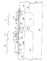
図1はバイポーラートランジスタ60と、pチャンネルトランジスタ64および68を断面図で示している。この構造は、この実施例の場合、p形シリコンである基板12中へ形成される。バイポーラートランジスタ60中の埋め込みn+領域14は、従来の意味のサブコレクターとして働き、n+領域25がそれに対する表面コンタクトとなる。n領域18aは、バイポーラートランジスタ60のコレクター領域であり、またpチャンネルトランジスタ64のウエル領域になっている。n領域18bはpチャンネルトランジスタ68のウエル領域である。真正ベース26はn領域18a−b中に設けられたp形領域である。エミッター電極30はドープされた多結晶シリコン層でよく、それは絶縁層24中の開口部を通って真正ベース領域26へ延びている。タングステンシリサイド層32がエミッター電極30を覆っている。p+領域52aはバイポーラートランジスタ60の外因性(不純物)ベース領域であり、またpチャンネルトランジスタ64のソース/ドレイン領域の1つでもある。p+領域52はpチャンネルトランジスタ64および68の残りのソース/ドレイン領域として働く。ドープされた多結晶シリコンをトランジスタ64および68のゲート40を形成するために使用することができる。ゲート酸化物36がゲート40とn領域18との間に取り付けられる。埋め込み領域16は領域20の下側に位置する。フィールド絶縁領域22は真正ベース領域26をコレクターコンタクト25から分離し、またpチャンネルトランジスタ64と68とを互いに分離する。ゲート40をシリサイド化してTiSi2層56を形成することもオプションとして可能である。トランジスタ64および68の下のn+領域14は埋め込みp領域16によって分離され、n領域18a−bはp領域20によって分離されて、2つのトランジスタのn形領域18a−bが異なる電位を有することが許容される。
【0011】
図2は、n+埋め込み層14の上に、p埋め込み層16、n形領域18a−b、p形領域20、フィールド絶縁領域22、および絶縁層24を形成した後の構造10を示している。埋め込み層を形成する方法については、1990年9月18日付けのテキサスインスツルメンツ社に譲渡された米国特許第4,958,213号に述べられている。フィールド絶縁領域22を形成する方法については、1985年9月17日付けのテキサスインスツルメンツ社に譲渡された米国特許第4,541,167号に述べられている。絶縁層24は、アンチKooi(Anti Kooi)酸化の後に20Å以下の厚さにまでデグレーズ(deglaze)され、次に300Åオーダーの厚さに熱酸化して形成したダミーのゲート酸化物でもよい。本発明に従う融合BiCMOSデバイスの作製について、図3に示す構造に至るまでを次に説明する。
【0012】
構造10の表面がパターン化され、n形ドーパントを用いた打ち込みが行われて、深いn形領域(コレクターコンタクト25)が形成される。これは、図3に示すように、n領域18を貫通してサブコレクターのn+領域14まで延びている。次に、Vt調節用の打ち込みが、1つはNMOSトランジスタ(図示されていない)のため、もう1つはPMOSトランジスタ64および68のために実施されよう。更に図3を参照すると、ベース領域26が、パターン化されp形ドーパントの打ち込みがされて(例えば、ホウ素を10keVで7.0E13cm−2)、形成される。
【0013】
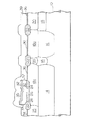
図4を参照すると、マスク層27が用いられてダミーの酸化物層24の一部が露出される。この露出した酸化物を次にエッチすることによって、ベース領域26の一部が露出される。マスク層27を次に除去して、デグレーズ(例えば、10%のHFで10秒間)が実施されて、界面酸化物が最小化される。図5を参照すると、多結晶シリコン層29等の導電層が2500Åオーダーの厚さに堆積される。次に、イオン打ち込みによって多結晶シリコン層29はn形にドープされる。あるいは、この多結晶シリコンは堆積工程中にその場ドープしてもよい。多結晶シリコン層29を覆ってタングステンシリサイドWSi2層32が堆積される。WSi232は500Åオーダーあるいはそれ以上の厚さのものでよい。次に、WSi2層32がアニールされる。多結晶シリコン層29とWSi232とは次にパターン化されエッチされて、図6に示すようにエミッター電極30が形成される。WSi2層32は以降の処理工程で、エミッター電極30の酸化を妨げる。
【0014】
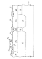
図7を参照すると、ダミー酸化物層24の露出した部分が次にデグレーズによって除去され、ゲート酸化物層36等の絶縁層で以て置き換えられる。ゲート酸化物層36は、熱酸化によって形成することができ、100Åオーダーの厚さを有する。ゲート酸化物層36の成長の間に、図7に示すように、エミッター電極30の縦方向端部には酸化物37が成長し、WSi232の上には二酸化シリコン層35が形成される。この熱酸化はエミッターのアニールも兼ねて十分高い温度で行うことができる。好適実施例では、900℃オーダーの温度が使用されている。図7に示すように、多結晶シリコン層39等の第2の導電性材料の層がLPCVD法によって構造10の表面を覆って堆積される。多結晶シリコン層39は3500Åオーダーの厚さを有する。多結晶シリコン層39は、次にイオン打ち込みによってドープすることができる。あるいは、多結晶シリコン層39は当業者には良く知られたように、その場ドーピングや(例えば、POCl3で以ての)気相でのドーピングのようなその他の手段でドープすることもできる。多結晶シリコン層39はパターン化されエッチされて、図8に示すようにゲート40が形成される。二酸化シリコン層35はこの多結晶シリコンゲートエッチングの際のエッチストップとして働く。
【0015】
図9を参照すると、表面を覆ってテトラエトキシシラン(TEOS)の層42が堆積される。次に、従来の方法を用いて、低濃度にドープされたドレイン(LDD)44の打ち込みが行われ、側壁スペーサー48、およびソース/ドレイン領域52が形成される。LDD44はオプションであり、必ずしも必要でないことを注意しておく。側壁スペーサー48は、誘電体層を堆積させ、異方性エッチングによってその誘電体層をエッチすることによって形成することができる。側壁スペーサー48はシリコン窒化物を含むことが好ましい。しかし代替えとして、酸化物や使い捨ての多結晶シリコンを使用してもよい。側壁スペーサー48を形成した後、ソース/ドレイン領域52が打ち込まれアニールされる。ドープされたエミッター電極は既に酸化物層36の形成時に”アニール”されているので、ソース/ドレイン領域52は低温(850℃オーダーの)でアニールされ、短チャンネル効果の低減化が図られる。TEOS層42および二酸化シリコン層35は、次に図10に示すように除去される。
【0016】
次に、ゲート40と、ソース/ドレイン領域52および52aとをシリサイド化することができる。構造10の表面を覆って高融点金属の層(図示されていない)が堆積される。この構造を、窒素を含む雰囲気中で、高速熱アニールを用いてアニールし、あるいは熱炉中でアニールする。これによって高融点金属層は露出シリコンと反応してシリサイドが形成される。図11を参照すると、ゲート40とソース/ドレイン領域52および52aの上にシリサイド層56が形成されている。ほかの場所には、高融点金属の窒化物層および/あるいは未反応金属(図示されていない)の層が形成される。高融点金属窒化物のこの層は次に除去される。
【0017】
上述の方法の完了に続いて、図1の能動領域へコンタクトを形成するための相互接続金属配線が施される。そのような相互接続を形成するための方法は当業者には良く知られている。次に、個々の回路が基板12の部分から分離されて、それぞれに対してワイヤボンディング、ダイレクトバンプボンディング等の当業者には良く知られた方法で外部接続が施される。個々の回路は次に、デュアルインラインパッケージ、チップキャリア、あるいはその他の型のパッケージ中へ実装される。そのような実装の例については1985年1月22日付けの、テキサスインスツルメンツ社へ譲渡された米国特許第4,495,376号に述べられている。
【0018】
本発明は例示実施例について説明してきたが、本説明は限定的な意図のものではない。本発明のその他の実施例とともに、例示実施例に対して各種の修正や組み合わせが可能であることは、本説明を参照することによって当業者には明らかであろう。従って、そのような実施例や修正および組み合わせはすべて、本発明の特許請求の範囲に包含されるものと解釈されるべきである。
【0019】
以上の説明の関して更に以下の項を開示する。
(1)半導体デバイスを作製するための方法であって、
a・第1のウエル領域を有する半導体母体の表面を覆って第1の絶縁層を形成すること、
b.前記第1のウエル領域の第1の部分へベース領域を打ち込みすること、
c.前記第1の絶縁層をエッチして、前記ベース領域の一部を露出させること、
d.前記半導体母体の表面を覆って第1のドープされた導電層を形成すること、
e.前記第1の導電層を覆ってタングステンシリサイド層を堆積させること、
f.前記タングステンシリサイド層および前記第1の導電層をエッチしてエミッター電極を形成し、前記第1の絶縁層の一部を露出させること、および
g.複数個のPMOSトランジスタを形成して、前記PMOSトランジスタのうちの少なくとも1個が、前記第1のウエル領域中に形成され前記ベース領域に接触する第1のソース/ドレイン領域を有するようにすること、
の工程を含む方法。
【0020】
(2)第1項記載の方法であって、前記複数個のPMOSトランジスタを形成する前記工程が、
a.前記エミッター電極を覆っていない前記第1の絶縁層の部分を除去すること、
b.前記半導体母体の表面と前記タングステンシリサイド層との上に第2の絶縁層を成長させること、
c.前記第2の絶縁層の上に複数個のゲート電極を形成することであって、少なくとも1個のゲート電極が前記第1のウエル領域の上に形成されるようにすること、および
d.前記半導体母体の前記表面に複数個のソース/ドレイン領域を形成することであって、前記複数個のソース/ドレイン領域が前記第1のソース/ドレイン領域を含み、前記第1のソース/ドレイン領域が、前記少なくとも1個のゲート電極と前記エミッター電極との間に形成されるようにすること、
の工程を含んでいる方法。
【0021】
(3)第2項記載の方法であって、前記ゲート電極を形成する前記工程が、
a.前記半導体母体の表面を覆って第2のドープされた導電層を形成すること、および
b.前記第2のドープされた導電層をエッチして前記複数個のゲート電極を形成し、そこにおいて前記エッチングが前記タングステンシリサイド層を覆う前記第2の絶縁層の上で止まるようにすること、
の工程を含んでいる方法。
【0022】
(4)第2項記載の方法であって、前記第2の絶縁層を850℃よりも高い温度で成長させる方法。
【0023】
(5)第2項記載の方法であって、更に、
a.前記ゲート電極を形成する前記工程の後に、各ゲート電極の反対側に、低濃度にドープしたドレインを打ち込みすること、および
b.前記ゲート電極の各々および前記エミッター電極に隣接して側壁スペーサーを形成すること、
の工程を含む方法。
【0024】
(6)第2項記載の方法であって、更に、前記ゲート電極と前記ソース/ドレイン領域とをシリサイド化する工程を含む方法。
【0025】
(7)第6項記載の方法であって、前記ゲート電極と前記ソース/ドレイン領域とをシリサイド化する前記工程が、
a.前記半導体母体の表面を覆って高融点金属の層を堆積させること、
b.窒素を含む雰囲気中で前記高融点金属の層をアニールして、前記ゲート電極と前記ソース/ドレイン領域とを覆ってシリサイド層を形成し、その他の場所には高融点金属の窒化物、未反応金属、あるいはそれらの組み合わせを含む未シリサイド化層を形成すること、および
c.前記未シリサイド化層をエッチすること、
の工程を含んでいる方法。
【0026】
(8)第1項記載の方法であって、前記ソース/ドレイン領域を形成する前記工程が、
a.前記ソース/ドレイン領域を打ち込みすること、および b.前記ソース/ドレイン領域を900℃よりも低い温度でアニールすること、
の工程を含んでいる方法。
【0027】
(9)第1項記載の方法であって、前記第1の絶縁層が300Åオーダーの厚さの酸化物を含み、前記第2の絶縁層が100Åオーダーの厚さの酸化物を含んでいる方法。
【0028】
(10)BiCMOSデバイスを作製する方法であって、
a.第1のウエル領域を有する半導体母体の表面に、複数個のフィールド絶縁領域を形成すること、
b.前記半導体母体の前記表面を覆って厚い酸化物層を形成すること、
c.前記フィールド絶縁領域の第1の領域に隣接して、前記第1のウエル領域の第1の部分中の前記厚い酸化物層を通してベース領域を打ち込みすること、
d.前記厚い酸化物層をエッチして、前記ベース領域を露出させること、
e.前記厚い酸化物層および前記ベース領域の前記露出された部分を覆って多結晶シリコンの第1の層を堆積させること、
f.前記第1の多結晶シリコン層を覆ってタングステンシリサイド層を堆積させること、
g.前記タングステンシリサイド層および前記第1の多結晶シリコン層をエッチして、前記ベース領域を覆うエミッター電極を形成し、前記厚い酸化物層の一部を露出させること、
h.前記厚い酸化物層の前記露出した部分を除去すること、
i.前記半導体母体の表面を覆ってゲート酸化物層を成長させること、
j.前記ゲート酸化物層を覆って多結晶シリコンの第2の層を堆積させること、
k.前記第2の多結晶シリコン層をエッチして複数個のゲート電極を形成することであって、前記ゲート電極のうちの少なくとも1個が前記第1のウエル領域の上に形成されるようにすること、
l.前記ゲート電極と前記エミッター電極に隣接して側壁スペーサーを形成すること、
m.各ゲート電極の反対側の前記半導体母体表面にソース/ドレイン領域を打ち込みすること、および
n.前記ソース/ドレイン領域を900℃よりも低い温度でアニールすること、
の工程を含む方法。
【0029】
(11)第10項記載の方法であって、更に、前記ゲート電極と前記ソース/ドレイン領域とをシリサイド化する工程を含む方法。
【0030】
(12)第11項記載の方法であって、前記ゲート電極と前記ソース/ドレイン領域とをシリサイド化する前記工程が、
a.前記半導体母体の表面を覆って高融点金属の層を堆積させること、
b.窒素を含む雰囲気中で前記高融点金属の層をアニールして、前記ゲート電極と前記ソース/ドレイン領域とを覆ってシリサイド層を形成し、その他の場所には高融点金属の窒化物、未反応金属、あるいはそれらの組み合わせを含む未シリサイド化層を形成すること、および
c.前記未シリサイド化層をエッチすること、
の工程を含んでいる方法。
【0031】
(13)BiCMOSデバイスであって、
a.ウエル領域、
b.前記ウエル領域中に位置する、タングステンシリサイド層と多結晶シリコン層とを含むエミッター電極を有するバイポーラートランジスタ、および
c.前記ウエル領域中に位置するPMOSトランジスタ、
を含むBiCMOSデバイス。
【0032】
(14)第13項記載のBiCMOSデバイスであって、前記PMOSトランジスタが前記バイポーラートランジスタのベース領域に接触するソース/ドレイン領域を有しているBiCMOSデバイス。
【0033】
(15)第13項記載のBiCMOSデバイスであって、前記バイポーラートランジスタが、ベース領域、エミッター電極、および前記エミッター電極と前記ベース領域との間に位置する厚い酸化物領域を含んでいるBiCMOSデバイス。
【0034】
(16)第15項記載のBiCMOSデバイスであって、前記PMOSトランジスタがゲート酸化物を含み、前記ゲート酸化物が前記厚い酸化物領域よりも薄いものであるBiCMOSデバイス。
【0035】
(17)第13項記載のBiCMOSデバイスであって、前記PMOSトランジスタがシリサイド化されたゲートを有しているBiCMOSデバイス。
【0036】
(18)同一のウエル領域18中に形成されたバイポーラートランジスタ60とPMOSトランジスタ64とを有する融合BiCMOSデバイス10。バイポーラートランジスタ60は、エミッター電極30、ベース領域26、およびウエル領域18で形成されるコレクター領域を含む。エミッター電極30は厚い酸化物24によってベース領域26から分離される。タングステンシリサイド層32がエミッター電極30を覆う。PMOSトランジスタ64は、ソース/ドレイン領域52、52a、ゲート電極40、およびゲート酸化物36を含む。PMOSトランジスタ64はオプションとしてLDD領域44を含むことができる。ソース/ドレイン領域52aはベース領域26に接触している。もし必要であれば、エミッター電極30およびゲート電極40をシリサイド化することができる。
【関連出願へのクロスリファレンス】
次の同時譲渡の特許出願をここに参考のために引用する。

【図面の簡単な説明】
【図1】本発明の好適実施例の断面図。
【図2】本発明の好適実施例の製造工程を示す図であって、n+埋め込み層14の上に、絶縁層24を形成した段階の断面図。
【図3】本発明の好適実施例の製造工程を示す図であって、ベース領域26の打ち込みを実施した段階の断面図。
【図4】本発明の好適実施例の製造工程を示す図であって、ベース領域26の一部を露出させた段階の断面図。
【図5】本発明の好適実施例の製造工程を示す図であって、WSi2層の堆積とアニールの段階の断面図。
【図6】本発明の好適実施例の製造工程を示す図であって、エミッター電極30形成段階の断面図。
【図7】本発明の好適実施例の製造工程を示す図であって、第2の導電層39を形成した段階の断面図。
【図8】本発明の好適実施例の製造工程を示す図であって、ゲート40を形成した段階の断面図。
【図9】本発明の好適実施例の製造工程を示す図であって、側壁スペーサー48を形成し、ソース/ドレイン領域52の打ち込み、アニールを行った段階の断面図。
【図10】本発明の好適実施例の製造工程を示す図であって、TEOS層42および二酸化シリコン層35を除去した段階の断面図。
【図11】本発明の好適実施例の製造工程を示す図であって、未反応の高融点金属を除去した段階の断面図。
【符号の説明】
10 融合BiCMOS構造
12 基板
14 埋め込みn+領域
16 p領域
18 n領域
20 領域
22 フィールド絶縁領域
24 絶縁層
25 n+コレクターコンタクト
26 真正ベース領域
27 マスク層
29 多結晶シリコン層
30 エミッター電極
32 タングステンシリサイド層
35 二酸化シリコン層
36 ゲート酸化物
37 酸化物
40 ゲート
42 TEOS層
44 LDD
48 側壁スペーサー
52,52a ソース/ドレイン(p+)領域
56 TiSi2層
60 バイポーラートランジスタ
64 pチャンネルトランジスタ
68 pチャンネルトランジスタ[0001]
[Industrial applications]
The present invention relates generally to semiconductor processing, and more particularly to a BiCMOS process.
[0002]
[Prior art]
Integrating MOSFET structures and bipolar transistors on the same substrate has become very promising. As is well known to those skilled in the art, digital and linear functions are often performed in integrated circuits using either bipolar or metal-oxide-semiconductor (MOS) technology. Of course, bipolar integrated circuits can provide faster operating speeds and higher drive currents than MOS circuits, at the expense of greater power consumption, especially when compared to complementary MOS (CMOS) circuits. Advances in manufacturing technology have made it possible to use both bipolar and CMOS transistors in the same integrated circuit (commonly referred to as BiCMOS devices). Bipolar transistors are typically made by using a moat region as the base for the bipolar transistor, doped polycrystalline silicon as the emitter, and a well region as the collector. Thereafter, the source / drain regions of the PMOS transistor are formed using the additional moat regions. Extending the current drive capability of bipolar transistors to greater levels is important for higher levels of bipolar integration or fused bipolar CMOS integration.
[0003]
Summary of the Invention
Disclosed is a BiCMOS device that includes a bipolar transistor and a PMOS transistor located in the same well region. A bipolar transistor includes an emitter electrode including a polycrystalline silicon layer and a tungsten silicide layer. The fabrication of the device begins with forming an insulating layer over the surface of the semiconductor body. Next, a base region is implanted into the first portion of the well region. Next, the first insulating layer is etched to expose a portion of the base region. A doped conductive layer is formed over the surface of the semiconductor body, and a tungsten silicide layer is deposited over the doped conductive layer. Next, the tungsten silicide layer and the doped conductive layer are etched to form an emitter electrode. Finally, a plurality of PMOS transistors are fabricated, at least one of the PMOS transistors having a first source / drain region formed in the well region and in contact with the base region.
[0004]
One advantage of the present invention is that it provides a simplified process for fabricating fused BiCMOS devices.
[0005]
Another feature of the present invention is the fusion of including WSi 2 to prevent the p + S / D implant from altering the gain of the bipolar transistor by protecting the emitter polysilicon from the p + S / D implant. To provide a bipolar / PMOS structure.
[0006]
Yet another feature of the present invention is to provide a BiCMOS device having an emitter electrode cap layer that withstands a high temperature oxide growth step.
[0007]
These and other features will be apparent to one of ordinary skill in the art with reference to the description herein and the drawings.
[0008]
In the drawings, corresponding elements have the same reference characters, unless otherwise specified.
[0009]
【Example】
As a preferred embodiment of the present invention, a BiCMOS structure having a combination of a bipolar transistor and a PMOS transistor in the same well region will be described here.
[0010]
FIG. 1 shows a
[0011]
FIG. 2 shows the
[0012]
The surface of
[0013]
Referring to FIG. 4, a portion of
[0014]
Referring to FIG. 7, the exposed portions of
[0015]
Referring to FIG. 9, a
[0016]
Next, the
[0017]
Subsequent to the completion of the above-described method, interconnect metallization is applied to form contacts to the active area of FIG. Methods for forming such interconnects are well known to those skilled in the art. Next, the individual circuits are separated from the portion of the
[0018]
Although the present invention has been described with reference to illustrative embodiments, this description is not intended to be limiting. Various modifications and combinations of the illustrative embodiments, as well as other embodiments of the invention, will be apparent to persons skilled in the art upon reference to the description. Therefore, all such embodiments, modifications and combinations are to be construed as falling within the scope of the claims of the present invention.
[0019]
The following items are further disclosed with respect to the above description.
(1) A method for manufacturing a semiconductor device, comprising:
a. forming a first insulating layer over the surface of the semiconductor body having the first well region;
b. Implanting a base region into a first portion of the first well region;
c. Etching the first insulating layer to expose a portion of the base region;
d. Forming a first doped conductive layer over the surface of the semiconductor body;
e. Depositing a tungsten silicide layer over the first conductive layer;
f. Etching the tungsten silicide layer and the first conductive layer to form an emitter electrode and exposing a portion of the first insulating layer; and g. Forming a plurality of PMOS transistors such that at least one of the PMOS transistors has a first source / drain region formed in the first well region and in contact with the base region; ,
A method comprising the steps of:
[0020]
(2) The method according to (1), wherein the step of forming the plurality of PMOS transistors includes:
a. Removing a portion of the first insulating layer that does not cover the emitter electrode;
b. Growing a second insulating layer on the surface of the semiconductor matrix and the tungsten silicide layer;
c. Forming a plurality of gate electrodes on the second insulating layer, wherein at least one gate electrode is formed on the first well region; and d. Forming a plurality of source / drain regions on the surface of the semiconductor body, wherein the plurality of source / drain regions include the first source / drain regions; Is formed between the at least one gate electrode and the emitter electrode.
Method comprising the steps of:
[0021]
(3) The method according to (2), wherein the step of forming the gate electrode comprises:
a. Forming a second doped conductive layer over the surface of the semiconductor body; and b. Etching the second doped conductive layer to form the plurality of gate electrodes, wherein the etching stops on the second insulating layer overlying the tungsten silicide layer;
Method comprising the steps of:
[0022]
(4) The method according to (2), wherein the second insulating layer is grown at a temperature higher than 850 ° C.
[0023]
(5) The method according to item 2, further comprising:
a. Implanting a lightly doped drain opposite the gate electrodes after the step of forming the gate electrodes; and b. Forming sidewall spacers adjacent to each of the gate electrodes and the emitter electrode;
A method comprising the steps of:
[0024]
(6) The method according to (2), further comprising a step of silicidizing the gate electrode and the source / drain region.
[0025]
(7) The method according to (6), wherein the step of silicidizing the gate electrode and the source / drain region includes:
a. Depositing a layer of a refractory metal over the surface of the semiconductor body;
b. The refractory metal layer is annealed in an atmosphere containing nitrogen to form a silicide layer covering the gate electrode and the source / drain regions. Forming an unsilicided layer comprising a metal, or a combination thereof; and c. Etching the unsilicided layer;
Method comprising the steps of:
[0026]
(8) The method according to (1), wherein the step of forming the source / drain regions includes:
a. Implanting the source / drain regions; and b. Annealing the source / drain regions at a temperature lower than 900 ° C .;
Method comprising the steps of:
[0027]
(9) The method according to (1), wherein the first insulating layer includes an oxide having a thickness on the order of 300 mm, and the second insulating layer includes an oxide having a thickness on the order of 100 mm. Method.
[0028]
(10) A method for manufacturing a BiCMOS device, comprising:
a. Forming a plurality of field insulating regions on the surface of the semiconductor body having the first well region;
b. Forming a thick oxide layer over the surface of the semiconductor body;
c. Implanting a base region adjacent the first region of the field isolation region through the thick oxide layer in a first portion of the first well region;
d. Etching the thick oxide layer to expose the base region;
e. Depositing a first layer of polysilicon over the thick oxide layer and the exposed portion of the base region;
f. Depositing a tungsten silicide layer over the first polysilicon layer;
g. Etching the tungsten silicide layer and the first polycrystalline silicon layer to form an emitter electrode covering the base region, exposing a portion of the thick oxide layer;
h. Removing the exposed portion of the thick oxide layer;
i. Growing a gate oxide layer over the surface of the semiconductor body;
j. Depositing a second layer of polysilicon over the gate oxide layer;
k. Etching the second polycrystalline silicon layer to form a plurality of gate electrodes, wherein at least one of the gate electrodes is formed on the first well region. thing,
l. Forming a sidewall spacer adjacent to the gate electrode and the emitter electrode;
m. Implanting source / drain regions on the semiconductor body surface opposite each gate electrode; and n. Annealing the source / drain regions at a temperature lower than 900 ° C .;
A method comprising the steps of:
[0029]
(11) The method according to (10), further comprising a step of silicidizing the gate electrode and the source / drain region.
[0030]
(12) The method according to (11), wherein the step of silicidizing the gate electrode and the source / drain region includes:
a. Depositing a layer of a refractory metal over the surface of the semiconductor body;
b. The refractory metal layer is annealed in an atmosphere containing nitrogen to form a silicide layer covering the gate electrode and the source / drain regions. Forming an unsilicided layer comprising a metal, or a combination thereof; and c. Etching the unsilicided layer;
Method comprising the steps of:
[0031]
(13) A BiCMOS device,
a. Well area,
b. A bipolar transistor having an emitter electrode including a tungsten silicide layer and a polycrystalline silicon layer located in the well region; and c. A PMOS transistor located in the well region;
A BiCMOS device comprising:
[0032]
(14) The BiCMOS device according to (13), wherein the PMOS transistor has a source / drain region in contact with a base region of the bipolar transistor.
[0033]
15. The BiCMOS device of claim 13, wherein said bipolar transistor includes a base region, an emitter electrode, and a thick oxide region located between said emitter electrode and said base region. .
[0034]
16. The BiCMOS device of
[0035]
(17) The BiCMOS device according to (13), wherein the PMOS transistor has a silicided gate.
[0036]
(18) A fused
[Cross-reference to related applications]
The following co-assigned patent applications are incorporated herein by reference.
[Brief description of the drawings]
FIG. 1 is a cross-sectional view of a preferred embodiment of the present invention.
FIG. 2 is a view showing a manufacturing process of the preferred embodiment of the present invention, and is a cross-sectional view at a stage where an insulating
FIG. 3 is a view showing a manufacturing process of the preferred embodiment of the present invention, and is a cross-sectional view at a stage where implantation of a
FIG. 4 is a view showing a manufacturing process of the preferred embodiment of the present invention, and is a cross-sectional view at a stage where a part of the
FIG. 5 is a cross-sectional view showing a manufacturing process of a preferred embodiment of the present invention, showing a stage of deposition and annealing of a WSi 2 layer.
FIG. 6 is a view showing a manufacturing process of the preferred embodiment of the present invention, and is a cross-sectional view at a stage of forming an
FIG. 7 is a view showing a manufacturing process of the preferred embodiment of the present invention, and is a cross-sectional view at a stage where a second
FIG. 8 is a view showing a manufacturing process of the preferred embodiment of the present invention, and is a cross-sectional view at a stage where a
FIG. 9 is a view showing a manufacturing process of the preferred embodiment of the present invention, and is a cross-sectional view at a stage where a
FIG. 10 is a cross-sectional view illustrating a manufacturing process of the preferred embodiment of the present invention, in which the
FIG. 11 is a view showing a manufacturing process of the preferred embodiment of the present invention, and is a cross-sectional view at a stage where an unreacted high melting point metal is removed.
[Explanation of symbols]
48
Claims (1)
a.第1のウエル領域を有する半導体母体の表面を覆って第1の絶縁層を形成すること、
b.前記第1のウエル領域の第1の部分へベース領域を打ち込みすること、
c.前記第1の絶縁層をエッチして、前記ベース領域の一部を露出させること、
d.前記半導体母体の表面を覆って第1のドープされた導電層を形成すること、
e.前記第1の導電層を覆ってタングステンシリサイド層を堆積させること、
f.前記タングステンシリサイド層および前記第1の導電層をエッチしてエミッター電極を形成し、前記第1の絶縁層の一部を露出させること、および
g.複数個のPMOSトランジスタを形成して、前記PMOSトランジスタのうちの少なくとも1個が、前記第1のウエル領域中に形成され前記ベース領域に接触する第1のソース/ドレイン領域を有するようにすること、
の工程を有し、
前記複数個のPMOSトランジスタを形成する工程が、
前記エミッター電極によって覆われない前記第1の絶縁層の部分を除去すること、
前記半導体母体と前記タングステンシリサイド層の表面に第2の絶縁層を成長すること、
前記第2の絶縁層の上に、複数のゲート電極を形成し、少なくとも1個のゲート電極を前記第1のウエル領域を覆うように形成すること、
前記半導体母体の表面に複数のソース/ドレイン領域を形成し、前記複数のソース/ドレイン領域は、前記第1のソース/ドレイン領域を含み、前記第1のソース/ドレイン領域は、前記少なくとも1個のゲート電極と前記エミッター電極の間に形成される前記方法。A method for manufacturing a semiconductor device, comprising:
a. Forming a first insulating layer over the surface of the semiconductor host having the first well region;
b. Implanting a base region into a first portion of the first well region;
c. Etching the first insulating layer to expose a portion of the base region;
d. Forming a first doped conductive layer over the surface of the semiconductor body;
e. Depositing a tungsten silicide layer over the first conductive layer;
f. Etching the tungsten silicide layer and the first conductive layer to form an emitter electrode and exposing a portion of the first insulating layer; and g. Forming a plurality of PMOS transistors such that at least one of the PMOS transistors has a first source / drain region formed in the first well region and in contact with the base region; ,
Having a process of
The step of forming the plurality of PMOS transistors includes:
Removing portions of the first insulating layer that are not covered by the emitter electrode;
Growing a second insulating layer on the surface of the semiconductor matrix and the tungsten silicide layer;
Forming a plurality of gate electrodes on the second insulating layer and forming at least one gate electrode so as to cover the first well region;
Forming a plurality of source / drain regions on a surface of the semiconductor body; the plurality of source / drain regions including the first source / drain regions; the method that is formed between the gate electrode and the emitter electrode.
Applications Claiming Priority (2)
| Application Number | Priority Date | Filing Date | Title |
|---|---|---|---|
| US161960 | 1993-12-03 | ||
| US08/161,960 US5441903A (en) | 1993-12-03 | 1993-12-03 | BiCMOS process for supporting merged devices |
Publications (2)
| Publication Number | Publication Date |
|---|---|
| JPH07321240A JPH07321240A (en) | 1995-12-08 |
| JP3594346B2 true JP3594346B2 (en) | 2004-11-24 |
Family
ID=22583555
Family Applications (1)
| Application Number | Title | Priority Date | Filing Date |
|---|---|---|---|
| JP33322294A Expired - Fee Related JP3594346B2 (en) | 1993-12-03 | 1994-12-05 | Method for manufacturing BiCMOS device |
Country Status (6)
| Country | Link |
|---|---|
| US (2) | US5441903A (en) |
| EP (1) | EP0656660B1 (en) |
| JP (1) | JP3594346B2 (en) |
| KR (1) | KR100360640B1 (en) |
| DE (1) | DE69433638T2 (en) |
| TW (1) | TW258830B (en) |
Families Citing this family (8)
| Publication number | Priority date | Publication date | Assignee | Title |
|---|---|---|---|---|
| JPH07335773A (en) * | 1994-06-10 | 1995-12-22 | Hitachi Ltd | Manufacture of semiconductor integrated circuit device |
| US5620908A (en) * | 1994-09-19 | 1997-04-15 | Kabushiki Kaisha Toshiba | Manufacturing method of semiconductor device comprising BiCMOS transistor |
| KR100223600B1 (en) * | 1997-01-23 | 1999-10-15 | 김덕중 | Semiconductor device and method of manufacturing the same |
| GB2340243A (en) * | 1998-07-30 | 2000-02-16 | P Shaw | Trailer apparatus for measuring ground density |
| JP4003438B2 (en) * | 2001-11-07 | 2007-11-07 | 株式会社デンソー | Semiconductor device manufacturing method and semiconductor device |
| JP4342579B2 (en) * | 2006-08-31 | 2009-10-14 | 三洋電機株式会社 | Semiconductor device |
| SE537230C2 (en) * | 2013-05-16 | 2015-03-10 | Klas Håkan Eklund Med K Eklund Innovation F | Bipolar transistor amplifier circuit with isolated gate |
| US11094806B2 (en) * | 2017-12-29 | 2021-08-17 | Texas Instruments Incorporated | Fabricating transistors with implanting dopants at first and second dosages in the collector region to form the base region |
Family Cites Families (7)
| Publication number | Priority date | Publication date | Assignee | Title |
|---|---|---|---|---|
| US4855244A (en) * | 1987-07-02 | 1989-08-08 | Texas Instruments Incorporated | Method of making vertical PNP transistor in merged bipolar/CMOS technology |
| SE461428B (en) * | 1988-06-16 | 1990-02-12 | Ericsson Telefon Ab L M | MANUFACTURING AFFAIRS ON A SUBSTANCES OF THE SEMI-THERMAL MATERIALS MAKING A BIPOLAR TRANSISTOR OR A BIPOLAR TRANSIST AND A FAILURE TRANSISTOR OR A BIPOLAR TRANSISTOR AND ANTELISTRANE AND A FAELETT TRANSISTOR WITH A CUSTOMER TRANSISTOR AND A FAILETT TRANSISTOR WITH A CUSTOMER TRANSISTOR |
| JPH02101747A (en) * | 1988-10-11 | 1990-04-13 | Toshiba Corp | Semiconductor integrated circuit and manufacture thereof |
| US4868135A (en) * | 1988-12-21 | 1989-09-19 | International Business Machines Corporation | Method for manufacturing a Bi-CMOS device |
| US5281544A (en) * | 1990-07-23 | 1994-01-25 | Seiko Epson Corporation | Method of manufacturing planar type polar transistors and combination bipolar/MIS type transistors |
| US5101257A (en) * | 1991-07-01 | 1992-03-31 | Motorola, Inc. | Semiconductor device having merged bipolar and MOS transistors and process for making the same |
| US5334549A (en) * | 1993-08-13 | 1994-08-02 | Texas Instruments Incorporated | BiCMOS process that supports merged devices |
-
1993
- 1993-12-03 US US08/161,960 patent/US5441903A/en not_active Expired - Fee Related
-
1994
- 1994-12-02 DE DE69433638T patent/DE69433638T2/en not_active Expired - Lifetime
- 1994-12-02 EP EP94119036A patent/EP0656660B1/en not_active Expired - Lifetime
- 1994-12-03 KR KR1019940032689A patent/KR100360640B1/en not_active IP Right Cessation
- 1994-12-05 JP JP33322294A patent/JP3594346B2/en not_active Expired - Fee Related
-
1995
- 1995-01-23 TW TW084100551A patent/TW258830B/zh not_active IP Right Cessation
- 1995-04-28 US US08/431,232 patent/US5811860A/en not_active Expired - Lifetime
Also Published As
| Publication number | Publication date |
|---|---|
| KR100360640B1 (en) | 2003-01-10 |
| DE69433638T2 (en) | 2004-08-05 |
| TW258830B (en) | 1995-10-01 |
| US5441903A (en) | 1995-08-15 |
| EP0656660A2 (en) | 1995-06-07 |
| EP0656660A3 (en) | 1998-01-07 |
| US5811860A (en) | 1998-09-22 |
| EP0656660B1 (en) | 2004-03-24 |
| KR950021503A (en) | 1995-07-26 |
| DE69433638D1 (en) | 2004-04-29 |
| JPH07321240A (en) | 1995-12-08 |
Similar Documents
| Publication | Publication Date | Title |
|---|---|---|
| JPH04226066A (en) | Bi-cmos device and its manufacture | |
| EP0694963B1 (en) | A method for fabricating BiCMOS semiconductor devices | |
| US4931407A (en) | Method for manufacturing integrated bipolar and MOS transistors | |
| JP3070674B2 (en) | Method for manufacturing semiconductor device | |
| JPH04226064A (en) | Interconnection body for semiconductor device use its manufacture | |
| KR100233153B1 (en) | Self-aligned silicided base bipolar transistor and resistor and method of fabrication | |
| JP3594346B2 (en) | Method for manufacturing BiCMOS device | |
| US5348896A (en) | Method for fabricating a BiCMOS device | |
| JP2776350B2 (en) | Method for manufacturing semiconductor integrated circuit device | |
| US4983531A (en) | Method of fabricating a single polysilicon bipolar transistor which is compatible with a method of fabricating CMOS transistors | |
| US5334549A (en) | BiCMOS process that supports merged devices | |
| JPH0581051B2 (en) | ||
| JP3165715B2 (en) | Method for manufacturing semiconductor device | |
| US6638829B1 (en) | Semiconductor structure having a metal gate electrode and elevated salicided source/drain regions and a method for manufacture | |
| JP2997123B2 (en) | Method for manufacturing semiconductor device | |
| JP3190370B2 (en) | BiCMOS device having closely spaced contacts and method of manufacturing the same | |
| JP3055781B2 (en) | Semiconductor device and manufacturing method thereof | |
| JP2578417B2 (en) | Method for manufacturing field effect transistor | |
| JP3700210B2 (en) | Manufacturing method of semiconductor device | |
| JP2770576B2 (en) | Method for manufacturing semiconductor device | |
| JPH04303963A (en) | Semiconductor device | |
| JPS61251164A (en) | Manufacture of bi-mis integrated circuit | |
| JPH11307771A (en) | Semiconductor device and its manufacture | |
| JPH05114702A (en) | Manufacture of semiconductor device | |
| JPH05175437A (en) | Manufacture of semiconductor device |
Legal Events
| Date | Code | Title | Description |
|---|---|---|---|
| A131 | Notification of reasons for refusal |
Free format text: JAPANESE INTERMEDIATE CODE: A131 Effective date: 20040409 |
|
| A521 | Written amendment |
Free format text: JAPANESE INTERMEDIATE CODE: A523 Effective date: 20040709 |
|
| TRDD | Decision of grant or rejection written | ||
| A01 | Written decision to grant a patent or to grant a registration (utility model) |
Free format text: JAPANESE INTERMEDIATE CODE: A01 Effective date: 20040803 |
|
| A61 | First payment of annual fees (during grant procedure) |
Free format text: JAPANESE INTERMEDIATE CODE: A61 Effective date: 20040831 |
|
| R150 | Certificate of patent or registration of utility model |
Free format text: JAPANESE INTERMEDIATE CODE: R150 |
|
| FPAY | Renewal fee payment (event date is renewal date of database) |
Free format text: PAYMENT UNTIL: 20070910 Year of fee payment: 3 |
|
| FPAY | Renewal fee payment (event date is renewal date of database) |
Free format text: PAYMENT UNTIL: 20080910 Year of fee payment: 4 |
|
| FPAY | Renewal fee payment (event date is renewal date of database) |
Free format text: PAYMENT UNTIL: 20080910 Year of fee payment: 4 |
|
| FPAY | Renewal fee payment (event date is renewal date of database) |
Free format text: PAYMENT UNTIL: 20090910 Year of fee payment: 5 |
|
| FPAY | Renewal fee payment (event date is renewal date of database) |
Free format text: PAYMENT UNTIL: 20100910 Year of fee payment: 6 |
|
| FPAY | Renewal fee payment (event date is renewal date of database) |
Free format text: PAYMENT UNTIL: 20100910 Year of fee payment: 6 |
|
| FPAY | Renewal fee payment (event date is renewal date of database) |
Free format text: PAYMENT UNTIL: 20110910 Year of fee payment: 7 |
|
| FPAY | Renewal fee payment (event date is renewal date of database) |
Free format text: PAYMENT UNTIL: 20120910 Year of fee payment: 8 |
|
| FPAY | Renewal fee payment (event date is renewal date of database) |
Free format text: PAYMENT UNTIL: 20130910 Year of fee payment: 9 |
|
| R250 | Receipt of annual fees |
Free format text: JAPANESE INTERMEDIATE CODE: R250 |
|
| LAPS | Cancellation because of no payment of annual fees |