JP3578952B2 - Vehicle air duct and garnish structure - Google Patents
Vehicle air duct and garnish structure Download PDFInfo
- Publication number
- JP3578952B2 JP3578952B2 JP33541799A JP33541799A JP3578952B2 JP 3578952 B2 JP3578952 B2 JP 3578952B2 JP 33541799 A JP33541799 A JP 33541799A JP 33541799 A JP33541799 A JP 33541799A JP 3578952 B2 JP3578952 B2 JP 3578952B2
- Authority
- JP
- Japan
- Prior art keywords
- duct
- garnish
- air
- air duct
- vehicle
- Prior art date
- Legal status (The legal status is an assumption and is not a legal conclusion. Google has not performed a legal analysis and makes no representation as to the accuracy of the status listed.)
- Expired - Fee Related
Links
Images


Classifications
-
- B—PERFORMING OPERATIONS; TRANSPORTING
- B60—VEHICLES IN GENERAL
- B60H—ARRANGEMENTS OF HEATING, COOLING, VENTILATING OR OTHER AIR-TREATING DEVICES SPECIALLY ADAPTED FOR PASSENGER OR GOODS SPACES OF VEHICLES
- B60H1/00—Heating, cooling or ventilating [HVAC] devices
- B60H1/00007—Combined heating, ventilating, or cooling devices
- B60H1/00207—Combined heating, ventilating, or cooling devices characterised by the position of the HVAC devices with respect to the passenger compartment
-
- B—PERFORMING OPERATIONS; TRANSPORTING
- B60—VEHICLES IN GENERAL
- B60H—ARRANGEMENTS OF HEATING, COOLING, VENTILATING OR OTHER AIR-TREATING DEVICES SPECIALLY ADAPTED FOR PASSENGER OR GOODS SPACES OF VEHICLES
- B60H1/00—Heating, cooling or ventilating [HVAC] devices
- B60H1/24—Devices purely for ventilating or where the heating or cooling is irrelevant
- B60H1/247—Disposition of several air-diffusers in a vehicle for ventilation-air circulation in a vehicle cabin
-
- B—PERFORMING OPERATIONS; TRANSPORTING
- B60—VEHICLES IN GENERAL
- B60H—ARRANGEMENTS OF HEATING, COOLING, VENTILATING OR OTHER AIR-TREATING DEVICES SPECIALLY ADAPTED FOR PASSENGER OR GOODS SPACES OF VEHICLES
- B60H1/00—Heating, cooling or ventilating [HVAC] devices
- B60H1/34—Nozzles; Air-diffusers
- B60H1/3414—Nozzles; Air-diffusers with means for adjusting the air stream direction
- B60H1/3428—Nozzles; Air-diffusers with means for adjusting the air stream direction using a set of pivoting shutters and a pivoting frame
-
- B—PERFORMING OPERATIONS; TRANSPORTING
- B60—VEHICLES IN GENERAL
- B60R—VEHICLES, VEHICLE FITTINGS, OR VEHICLE PARTS, NOT OTHERWISE PROVIDED FOR
- B60R13/00—Elements for body-finishing, identifying, or decorating; Arrangements or adaptations for advertising purposes
- B60R13/02—Internal Trim mouldings ; Internal Ledges; Wall liners for passenger compartments; Roof liners
- B60R13/0237—Side or rear panels
- B60R13/025—Pillars; Roof rails
-
- B—PERFORMING OPERATIONS; TRANSPORTING
- B60—VEHICLES IN GENERAL
- B60R—VEHICLES, VEHICLE FITTINGS, OR VEHICLE PARTS, NOT OTHERWISE PROVIDED FOR
- B60R13/00—Elements for body-finishing, identifying, or decorating; Arrangements or adaptations for advertising purposes
- B60R13/02—Internal Trim mouldings ; Internal Ledges; Wall liners for passenger compartments; Roof liners
- B60R13/0212—Roof or head liners
- B60R13/0225—Roof or head liners self supporting head liners
-
- B—PERFORMING OPERATIONS; TRANSPORTING
- B60—VEHICLES IN GENERAL
- B60R—VEHICLES, VEHICLE FITTINGS, OR VEHICLE PARTS, NOT OTHERWISE PROVIDED FOR
- B60R13/00—Elements for body-finishing, identifying, or decorating; Arrangements or adaptations for advertising purposes
- B60R13/02—Internal Trim mouldings ; Internal Ledges; Wall liners for passenger compartments; Roof liners
- B60R2013/0287—Internal Trim mouldings ; Internal Ledges; Wall liners for passenger compartments; Roof liners integrating other functions or accessories
Description
【0001】
【発明の属する技術分野】
本発明は、より広い視界を得るのに好適な車両のエアダクト及びガーニッシュ構造に関する。
【0002】
【従来の技術】
ピラーの室内側にエアダクトを配置し、このエアダクトをガーニッシュで覆う構造を有する車両がある。このエアダクト及びガーニッシュ構造を次図で説明する。
図14は従来の車両のエアダクト及びガーニッシュ構造を示す断面図であり、アウタパネル100とインナパネル101とでピラー102を形成し、このピラー102の側方にウインドガラス103を取付け、これらのピラー102とウインドガラス103の端部との室内側にエアダクト104を配置し、このエアダクト104の更に室内側にガーニッシュ105を取付けてエアダクト104をガーニッシュ105で覆い、ウインドガラス103の内面におけるガーニッシュ105の端部105bからピラー102側の範囲を黒く塗って不透明な黒塗り部106としたことを示す。
【0003】
【発明が解決しようとする課題】
上記技術のように、ピラー102の厚みが大きいものでは、このピラー102だけの室内側にエアダクト104を配置すると、エアダクト104が室内に大きく突出して室内スペースが小さくなる。
【0004】
エアダクト104の断面積は、所定の通気量を確保する必要があって変更できないため、上記したような室内スペースが小さくなるのを回避するためには、ピラー102と、このピラー102に隣り合うウインドガラス103との境の室内側にエアダクト104を配置することで、エアダクト104の室内への突出量を小さくする。
しかし、エアダクト104がウインドガラス103側へ延びるため、ガーニッシュ105がウインドガラス103の一部を覆い、視界が悪くなる。
【0005】
そこで、本発明の目的は、エアダクトをピラー部分に配置する場合に、より広い視界を得ることができる車両のエアダクト及びガーニッシュ構造を提供することにある。
【0006】
【課題を解決するための手段】
上記目的を達成するために請求項1は、左右一方のリヤサイドパネルの下部内側にエアコンディッショニングユニットを設けるとともに、天井に平面視L字形で前後の各車幅中央に吹出し口を設けたルーフダクトを配置し、リヤサイドパネルの上部内側に形成したリヤピラーとこのリヤピラーの前方に位置するクオータガラスとの境にて、室内側にエアコンディショニングユニットとルーフダクトとを連結するエアダクトを立向きに配置し、このエアダクトをガーニッシュで覆った車両において、エアダクトのクオータガラス寄りの部分を、エアダクト外へ突となる凸断面部とし、この凸断面部に沿ってガーニッシュを廻り込ませることで、このガーニッシュのクオータガラス寄りの端部を、リヤピラーに寄せたことを特徴とする。
【0007】
リヤピラーとクオータガラスとの境にて、室内側に立向きに配置するとともに、エアダクト外へ突となる凸断面部とした、エアダクトのクオータガラス寄りの部分に沿ってガーニッシュを廻り込ませ、ガーニッシュのクオータガラス寄りの端部をリヤピラーに寄せる。
【0008】
この結果、クオータガラスにおいて、ガーニッシュのクオータガラス寄りの端部に覆われる部分が小さくなり、また、エアダクトに凸断面部を設けたため、エアダクトの断面積を小さくすることなしに、より広い後方視界を得ることができる。
【0009】
【発明の実施の形態】
本発明の実施の形態を添付図に基づいて以下に説明する。なお、図面は符号の向きに見るものとする。
図1は本発明に係るエアダクト及びガーニッシュ構造を採用した車両の斜視図であり、車両10の右リヤサイドパネル(不図示)の内側に、ヒータユニット、クーラユニット、ブロアモータからなるエアコンディショニングユニット11を配置し、このエアコンディショニングユニット11にエアダクトとしてのサイドダクト12を介してルーフパネル13の下側に配置したルーフダクト14を接続した後席用のエアコンディショナ15を示す。なお、17は左リヤサイドパネル、18はバックドアである。
【0010】
図2は本発明に係る車両のルーフダクトの分解斜視図であり、ルーフダクト14は、ルーフパネル13(図1参照)の内側に取付けるルーフライニング21と、このルーフライニング21の上面に取付ける樹脂製のダクト用パネル22とから形成するものである。
ルーフライニング21は、車幅中央に、後席のセカンドシート、サードシートへエアコンディショニングユニット11(図1参照)で温度、量を調整した空調風を吹出すための前部吹出し部24及び後部吹出し部25を取付けたものである。
【0011】
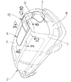
図3は図1の3−3線断面図であり、ダクト用パネル22を水平に切断した断面図である。
ダクト用パネル22は、平面視略L字形に形成したものであり、このダクト用パネル22と、ルーフライニング21によって、ルーフダクト14は、平面視矩形のエア溜まり室状に形成するとともに、車幅中央で天井の後部から略中央部まで延ばし、エア溜まり室の後部側方に、サイドダクト12(図1参照)に接続するエア導入部26を設け、下面、即ちルーフライニング21に設けた前部・後部吹出し部24,25への送風を分配する配風板27を内部、即ちダクト用パネル22の内面に設けたものである。なお、21aはルーフライニング21に形成した凹部である。
【0012】
図4は本発明に係る車両の天井の底面図であり、ルーフライニング21に取付けた前部吹出し部24は、ベース部材31に、空調風の吹出し方向を調整するための風向調整機構32,32と、センタルームランプ33と、空調風の温度、量を調整する操作を行うための空調操作部34とを取付けたものである。
また、後部吹出し部25は、ベース部材35に風向調整機構32,32を取付けたものである。なお、36はリヤルームランプである。
【0013】
図5は本発明に係る車両のエアコンディショナの前部・後部吹出し部の分解斜視図であり、前部吹出し部24のベース部材31に、風向調整機構32,32を取付けるための風向調整機構取付穴41,41と、センタルームランプ33を取付けるためのランプ取付穴42と、空調操作部34(不図示。図4参照。)を取付ける空調操作部取付部43を設け、また、後部吹出し部25のベース部材35に風向調整機構32,32を取付けるための風向調整機構取付穴44,44を設け、ルーフライニング21の凹部21aに、前部吹出し部24を取付けるための前部吹出し部取付穴45と、後部吹出し部25を取付けるための後部吹出し部取付穴46とを開けた状態を示す。
センタルームランプ33は、バルブ33aと、このバルブ33aを保持するバルブ保持部33bと、レンズ33cとからなる。
【0014】
図6は本発明に係る車両のエアコンディショナの風向調整機構及びその取付穴の分解斜視図である。
風向調整機構32は、複数のフィン51・・・(・・・は複数個を示す。以下同様。)と、これらのフィン51・・・をそれぞれスイング自在に保持するフィン保持部52とからなる。なお、53はフィン保持部52の外周部に取付けた板ばねである。
フィン51の一つにつまみ部54を設け、このつまみ部54を倒すことで、各フィン51を同時に連動させて倒すことができる。
【0015】
風向調整機構取付穴41は、内周部41aに凹凸を形成したものであり、41b・・・は山部、41c・・・は谷部である。
上記した内周部41aは、複数の山部41b及び複数の谷部41cで構成する鋸歯部を形成したものである。
風向調整機構取付穴44(図5参照)は、風向調整機構取付部41と同一形状を有する。
【0016】
図7は図6の7−7線断面図であり、フィン51の側部に凸部51a,51aを設け、この凸部51a,51aでフィン51をフィン保持部52にスイング自在に取付け、フィン保持部52の上部に突出部52aを設け、この突出部52aに板ばね53をはめ込んで取付け、この板ばね53の先端部53aを風向調整機構取付穴41の内周部41aに当てたことを示す。
【0017】
以上の図6、図7で説明したように、風向調整機構取付穴41の凹凸を有する内周部41aに板ばね53の先端部53aを当てたことで、風向調整機構取付穴41に対して風向調整機構32を回転させることができるとともに、風向調整機構32が振動等で回転することを防止することができる。
【0018】
図8は図1の8−8線断面図であり、ルーフパネル57とルーフライニング21との間に偏平状に、そして、長手方向を車両の前後方向にしてルーフダクト14を設けたことを示す。
このように、ルーフダクト14を偏平状に形成したことで、ルーフライニング21を高い位置に配置することができ、車両の高さを抑えつつ、室内スペースをを大きくすることができる。
【0019】
図9は本発明に係る車両のエアコンディショナのエアコンディショニングユニット及びサイドダクトを示す側面図であり、エアコンディショニングユニット11に接続したサイドダクト12を、ウインドガラスとしてのクオータガラス61の後部とクオータガラス61の後方に位置するリヤピラー(後述する。)との室内側に配置し、リヤピラーと共にリヤガーニッシュ63で覆うことを示す。
図10は図1の10−10線断面図であり、エアコンディショニングユニット11にサイドダクト12を介してルーフダクト14のエア導入部26を接続した状態を示す。
【0020】
図11は本発明に係るサイドダクトの横断面図であり、クオータガラス61とピラーとしてのリヤピラー62との境にて、室内側にサイドダクト12を立向きに配置し、このサイドダクト12をガーニッシュとしてのリヤガーニッシュ63で覆ったことを示す。なお、65,66はリヤピラー62を構成する右リヤサイドパネル及びインナパネル、67はクオータガラス61の内面を黒く塗って不透明とした黒塗り部である。
【0021】
サイドダクト12は、クオータガラス61寄りの部分12aを、ダクト外へ突となる凸断面部とし、断面積をSとした部材である。
リヤガーニッシュ63は、前部63aをサイドダクト12の凸断面部(即ち、部分12a)に沿って廻り込ませ、クオータガラス61寄りの端部63bを、リヤピラー62に寄せた部材である。
【0022】
以上に述べたエアコンディショナ15における送風状態を次に説明する。
図12は本発明に係る車両のエアコンディショナの送風状態を説明する作用図である。
後席のセカンドシートに着座した乗員P1が、天井に設けた空調操作部34を操作してエアコンディショニングユニット11内のブロアモータを作動させる。これにより、エアコンディショニングユニット11からサイドダクト12を介してルーフダクト14内に空調風が供給される。
【0023】
そして、空調風の一部はルーフダクト14の前部吹出し部24からセカンドシートの乗員P1側へ矢印のように吹出し、また、空調風の一部は、後部吹出し部25からサードシートの乗員P2側へ矢印のように吹出す。
各乗員P1,P2は、好みに応じて風向調整機構32で空調風の吹出し方向を調節することができる。
また、運転席及び助手席の乗員Dは、インストルメントパネル69に設けた図示せぬ吹出し部の風向調整機構で空調風の吹出し方向を調節することができる。
【0024】
以上に述べたサイドダクト12及びリヤガーニッシュ63の構造の作用を次に説明する。
図13は本発明に係るサイドダクト及びリヤガーニッシュ構造の作用を説明する作用図であり、本実施の形態と比較例(図14に示した従来の技術である。)とを対比させて説明する。
本実施の形態において、例えば、ドライバー等の乗員D(図12参照)の目の位置を点Eとし、乗員Dがクオータガラス61を通して車外を見ることができるクオータガラス61の最後端部(即ちリヤガーニッシュ63の端部63bに相当する部分であり、点で示す。)に向けた視線をGL1とする。
比較例において、エアダクト104のウインドガラス103寄りの部分を104a、ガーニッシュ105のウインドガラス103寄りの端部(点で示す。)を105bとする。
【0025】
本実施の形態では、乗員Dの車両後方の視界を広くした。
即ち、リヤガーニッシュ63の端部63bを比較例のガーニッシュ105の端部105bに対して距離GAだけ車両後方(リヤピラー62)に寄せた。
この場合、比較例のエアダクト104の断面積Sを本実施の形態のリヤダクト12でも確保(本実施の形態のサイドダクト12の断面積を比較例のエアダクト104の断面積と同一のSとする。)するために、本実施の形態のリヤダクト12のクオータガラス61寄りの部分12aを比較例のエアダクト104のウインドガラス103寄りの部分104aよりも距離DUだけ前方に突出させて凸断面部とした。
【0026】
これにより、比較例において、乗員Dがウインドガラス103を通して車外を見ることができるウインドガラス103の最後端部(即ちガーニッシュ105の端部105bに相当する。)に向けた視線をGL2とすると、本実施の形態の視線GL1は、比較例の視線GL2よりも車両後方に向けらるため、本実施の形態では、比較例よりも広い後方視界を得ることができる。
【0027】
以上説明したように、本発明は、リヤピラー62とクオータガラス61との境にて、室内側にサイドダクト12を立向きに配置し、このサイドダクト12をリヤガーニッシュ63で覆った車両10(図1参照)において、サイドダクト12のクオータガラス61寄りの部分12aを、ダクト12外へ突となる凸断面部とし、この凸断面部に沿ってリヤガーニッシュ63を廻り込ませることで、このリヤガーニッシュ63のクオータガラス61寄りの端部63bを、リヤピラー62に寄せたことを特徴とする。
【0028】
上記構成により、クオータガラス61において、リヤガーニッシュ63のクオータガラス61寄りの端部63bに覆われる部分が小さくなり、また、サイドダクト12の前部に凸部断面部を設けたため、サイドダクト12の断面積を小さくすることなしに、より広い視界を得ることができる。
従って、例えば、車両の後退をより楽に行うことができる。
【0029】
尚、図11において、サイドダクト12は、クオータガラス61寄りの部分12aを凸断面部とし、リヤガーニッシュ63は、サイドダクト12の凸断面部に沿って廻り込ませた形状としたが、サイドダクト12は、クオータガラス61寄りの部分12aを図に示した形状に限らず、例えば、車両前方に凸な円形の凸断面部としてもよく、また、リヤガーニッシュ63は、前部をそのサイドダクト12のような車両前方に突な円形の凸断面部に沿って廻り込ませた円形状としてもよい。
【0030】
【発明の効果】
本発明は上記構成により次の効果を発揮する。
請求項1の車両のエアダクト及びガーニッシュ構造は、エアダクトのクオータガラス寄りの部分を、エアダクト外へ突となる凸断面部とし、この凸断面部に沿ってガーニッシュを廻り込ませることで、このガーニッシュのクオータガラス寄りの端部を、リヤピラーに寄せたので、クオータガラスにおいて、ガーニッシュのクオータガラス寄りの端部に覆われる部分が小さくなり、また、エアダクトに凸部断面部を設けたため、エアダクトの断面積を小さくすることなしに、広い後方視界を得ることができる。
従って、車両の後退等をより楽に行うことができる。
【図面の簡単な説明】
【図1】本発明に係るエアダクト及びガーニッシュ構造を採用した車両の斜視図
【図2】本発明に係る車両のルーフダクトの分解斜視図
【図3】図1の3−3線断面図
【図4】本発明に係る車両の天井の底面図
【図5】本発明に係る車両のエアコンディショナの前部・後部吹出し部の分解斜視図
【図6】本発明に係る車両のエアコンディショナの風向調整機構及びその取付穴の分解斜視図
【図7】図6の7−7線断面図
【図8】図1の8−8線断面図
【図9】本発明に係る車両のエアコンディショナのエアコンディショニングユニット及びサイドダクトを示す側面図
【図10】図1の10−10線断面図
【図11】本発明に係るサイドダクトの横断面図
【図12】本発明に係る車両のエアコンディショナの送風状態を説明する作用図
【図13】本発明に係るサイドダクト及びリヤガーニッシュ構造の作用を説明する作用図
【図14】従来の車両のエアダクト及びガーニッシュ構造を示す断面図
【符号の説明】
10…車両、11…エアコンディショニングユニット、12…エアダクト(サイドダクト)、12a…凸断面部(サイドダクトのクオータガラス寄りの部分)、14…ルーフダクト、24,25…吹出し口(前部吹出し部、後部吹出し部)、61…クオータガラス、62…リヤピラー、63…ガーニッシュ(リヤガーニッシュ)、63b…ガーニッシュのウインドガラス寄りの端部、65…右リヤサイドパネル。[0001]
TECHNICAL FIELD OF THE INVENTION
The present invention relates to a vehicle air duct and a garnish structure suitable for obtaining a wider field of view.
[0002]
[Prior art]
There is a vehicle having a structure in which an air duct is arranged inside a pillar and the air duct is covered with a garnish. This air duct and garnish structure will be described with reference to the following drawings.
FIG. 14 is a cross-sectional view showing a conventional air duct and garnish structure of a vehicle. A
[0003]
[Problems to be solved by the invention]
In the case where the
[0004]
Since the cross-sectional area of the
However, since the
[0005]
Therefore, an object of the present invention is to provide an air duct and a garnish structure of a vehicle that can obtain a wider field of view when the air duct is arranged in a pillar portion.
[0006]
[Means for Solving the Problems]
In order to achieve the above object, a roof duct is provided in which an air conditioning unit is provided inside a lower portion of one of right and left rear side panels, and an outlet is provided in a ceiling in an L-shape in plan view at the center of each of front and rear vehicle widths. was placed at the boundary between the rear pillar formed in the upper inner side of the rear side panel and quarter glass located in front of the rear pillar, arranged d adduct connecting the air conditioning unit and the roof duct to the indoor side elevational direction and, in a vehicle covering the air duct in the garnish, a quarter glass side of the portion of the e adduct, a convex cross section as a collision outside air duct, by incorporated around the gas Nisshu along the convex cross section, the end of the quarter glass side of the garnish, characterized in that closer to the rear pillar.
[0007]
At the boundary between the rear pillar and the quarter glass, as well as arranged on the indoor side elevation direction, and a convex cross section as a collision outside air duct causes incorporated around the garnish along the quarter glass side of the portion of the air duct, gather the end of the quarter glass side of the garnish to the rear pillar.
[0008]
As a result, in the quarter glass, the portion of the garnish covered by the quarter glass is reduced, and the convex section is provided in the air duct, so that a wider rear view can be obtained without reducing the cross-sectional area of the air duct. Obtainable.
[0009]
BEST MODE FOR CARRYING OUT THE INVENTION
An embodiment of the present invention will be described below with reference to the accompanying drawings. The drawings should be viewed in the direction of reference numerals.
FIG. 1 is a perspective view of a vehicle employing an air duct and a garnish structure according to the present invention. An
[0010]
FIG. 2 is an exploded perspective view of the roof duct of the vehicle according to the present invention. The
The
[0011]
FIG. 3 is a sectional view taken along line 3-3 of FIG. 1 and is a sectional view of the
The
[0012]
FIG. 4 is a bottom view of the ceiling of the vehicle according to the present invention. A
In addition, the
[0013]
FIG. 5 is an exploded perspective view of the front and rear outlets of the air conditioner of the vehicle according to the present invention, and shows a wind direction adjusting mechanism for attaching the wind
The
[0014]
FIG. 6 is an exploded perspective view of a wind direction adjusting mechanism of a vehicle air conditioner according to the present invention and a mounting hole thereof.
The wind
By providing a
[0015]
The wind direction adjusting
The inner
The wind direction adjusting mechanism mounting hole 44 (see FIG. 5) has the same shape as the wind direction adjusting
[0016]
FIG. 7 is a cross-sectional view taken along the line 7-7 in FIG. 6, in which
[0017]
As described above with reference to FIGS. 6 and 7, the
[0018]
FIG. 8 is a cross-sectional view taken along line 8-8 of FIG. 1, and shows that the
By forming the
[0019]
FIG. 9 is a side view showing an air conditioning unit and a side duct of an air conditioner for a vehicle according to the present invention. The
FIG. 10 is a sectional view taken along line 10-10 of FIG. 1 and shows a state in which the
[0020]
FIG. 11 is a cross-sectional view of a side duct according to the present invention. A
[0021]
The
The
[0022]
Next, the air blowing state in the
FIG. 12 is an operation diagram illustrating the air blowing state of the air conditioner of the vehicle according to the present invention.
The occupant P1 sitting on the second seat in the rear seat operates the air
[0023]
Part of the conditioned air is blown from the
Each of the occupants P1 and P2 can adjust the blowing direction of the conditioned air by the wind
In addition, the occupant D in the driver's seat and the passenger's seat can adjust the blowing direction of the conditioned air by a wind direction adjusting mechanism of a blowing unit (not shown) provided in the
[0024]
The operation of the above-described structures of the
FIG. 13 is an operation diagram for explaining the operation of the side duct and rear garnish structure according to the present invention. The present embodiment will be described in comparison with a comparative example (the prior art shown in FIG. 14). .
In the present embodiment, for example, the position of the eyes of an occupant D (see FIG. 12) such as a driver is set to a point E, and the occupant D can see the outside of the vehicle through the
In the comparative example, a portion of the
[0025]
In the present embodiment, the occupant D has a wider view behind the vehicle.
That is, the
In this case, the cross-sectional area S of the
[0026]
As a result, in the comparative example, assuming that the line of sight toward the rearmost end (that is, corresponding to the
[0027]
As described above, according to the present invention, the
[0028]
With the above configuration, in the
Therefore, for example, the backward movement of the vehicle can be performed more easily.
[0029]
In FIG. 11, the
[0030]
【The invention's effect】
The present invention has the following effects by the above configuration.
Air duct and garnish structure of a vehicle of claim 1, a quarter glass side of the portion of the air duct, a convex cross section as a collision outside air duct, by incorporated around the garnish along the convex cross section, the garnish of the end of the quarter glass closer, because closer to the rear pillar, the quarter glass, partially covered with the end of the quarter glass side of the garnish is reduced, also due to the provision of the protrusion cross section on the air duct, the air duct A wide rear view can be obtained without reducing the cross-sectional area.
Accordingly, the vehicle can be easily moved backward.
[Brief description of the drawings]
FIG. 1 is a perspective view of a vehicle employing an air duct and a garnish structure according to the present invention; FIG. 2 is an exploded perspective view of a roof duct of the vehicle according to the present invention; FIG. 4 is a bottom view of the ceiling of the vehicle according to the present invention. FIG. 5 is an exploded perspective view of the front and rear outlets of the air conditioner of the vehicle according to the present invention. FIG. 6 is an exploded perspective view of the air conditioner of the vehicle according to the present invention. FIG. 7 is an exploded perspective view of a wind direction adjusting mechanism and a mounting hole thereof. FIG. 7 is a sectional view taken along line 7-7 of FIG. 6. FIG. 8 is a sectional view taken along line 8-8 of FIG. 1. FIG. FIG. 10 is a cross-sectional view taken along line 10-10 of FIG. 1; FIG. 11 is a cross-sectional view of the side duct according to the present invention; FIG. 12 is a vehicle air conditioner according to the present invention; FIG. 13 is an operation diagram illustrating the blower state of the shocker. Cross-sectional view showing the air duct and garnish structure of operational view [14] Conventional vehicle illustrating the operation of the side duct and a rear garnish structure according to the present invention DESCRIPTION OF REFERENCE NUMERALS
DESCRIPTION OF
Claims (1)
前記エアダクトのクオータガラス寄りの部分を、エアダクト外へ突となる凸断面部とし、この凸断面部に沿って前記ガーニッシュを廻り込ませることで、このガーニッシュのクオータガラス寄りの端部を、前記リヤピラーに寄せたことを特徴とする車両のエアダクト及びガーニッシュ構造。 An air conditioning unit is provided inside the lower part of one of the left and right rear side panels, and a roof duct is provided on the ceiling, with an L-shape in plan view and a vent at the center of each of the front and rear vehicle widths, and is formed inside the upper part of the rear side panel. at the boundary between the quarter glass located in front of the rear pillar and the rear pillar, arranged d adduct that connects to the air conditioning unit to the indoor side and the roof duct standing orientation, covering the air duct with garnish vehicle in,
Quotas glass side of the part before Symbol air duct, a convex cross section as a collision outside air duct, by incorporated around the garnish along the convex cross section, the end of the quarter glass side of the garnish, air duct and garnish structure of a vehicle, characterized in that submitted to the rear pillar.
Priority Applications (3)
| Application Number | Priority Date | Filing Date | Title |
|---|---|---|---|
| JP33541799A JP3578952B2 (en) | 1999-11-26 | 1999-11-26 | Vehicle air duct and garnish structure |
| DE10058366A DE10058366C2 (en) | 1999-11-26 | 2000-11-24 | Air guiding and cladding structure for an automobile |
| US09/721,655 US6315354B1 (en) | 1999-11-26 | 2000-11-27 | Automotive air duct and garnish structure |
Applications Claiming Priority (1)
| Application Number | Priority Date | Filing Date | Title |
|---|---|---|---|
| JP33541799A JP3578952B2 (en) | 1999-11-26 | 1999-11-26 | Vehicle air duct and garnish structure |
Publications (2)
| Publication Number | Publication Date |
|---|---|
| JP2001150928A JP2001150928A (en) | 2001-06-05 |
| JP3578952B2 true JP3578952B2 (en) | 2004-10-20 |
Family
ID=18288330
Family Applications (1)
| Application Number | Title | Priority Date | Filing Date |
|---|---|---|---|
| JP33541799A Expired - Fee Related JP3578952B2 (en) | 1999-11-26 | 1999-11-26 | Vehicle air duct and garnish structure |
Country Status (3)
| Country | Link |
|---|---|
| US (1) | US6315354B1 (en) |
| JP (1) | JP3578952B2 (en) |
| DE (1) | DE10058366C2 (en) |
Families Citing this family (34)
| Publication number | Priority date | Publication date | Assignee | Title |
|---|---|---|---|---|
| DE10029612A1 (en) * | 1999-07-14 | 2001-01-18 | Volkswagen Ag | Display and/or operating device for comfort control in motor vehicle comprises one structural unit together with ventilation device on mid console |
| US6776451B2 (en) * | 2000-12-01 | 2004-08-17 | Alfa Leisure, Inc. | Motorhome HVAC system |
| US6807735B2 (en) | 2000-12-01 | 2004-10-26 | Alfa Leisure, Inc. | Method of fabricating a motorhome |
| KR100382155B1 (en) * | 2001-04-12 | 2003-05-09 | 조성호 | movable vent grill frame for an automobile |
| DE60300983T2 (en) * | 2002-03-11 | 2006-05-18 | Intier Automotive Inc., Newmarket | VENTILATION SYSTEM INTEGRATED IN THE VEHICLE ROOF, COMPRISED WITH A PIECE OF AIR CONDITIONING IN THE ROOF AND IN A PILLAR |
| US6749255B2 (en) * | 2002-06-21 | 2004-06-15 | Lear Corporation | Blow molded multiple function assemblies for vehicle headliners |
| US6834913B2 (en) * | 2002-11-13 | 2004-12-28 | Visteon Global Technologies, Inc. | Structural composite air handling duct |
| DE10255803B3 (en) * | 2002-11-29 | 2004-05-06 | Daimlerchrysler Ag | Passenger compartment for vehicle has transverse air channel spaced out from seat banks under roof |
| US7044848B2 (en) * | 2003-09-12 | 2006-05-16 | Ford Global Technologies, Llc | Fresh air intake for a vehicle |
| US8721407B2 (en) * | 2003-09-12 | 2014-05-13 | Ford Global Technologies, Llc | Vehicle having fresh air intake |
| DE10347308A1 (en) * | 2003-10-08 | 2005-05-04 | Volkswagen Ag | Air supply device for air conditioning a vehicle interior of a vehicle, in particular a utility vehicle |
| DE10353823B4 (en) * | 2003-11-18 | 2013-07-11 | Volkswagen Ag | Ventilation device for a vehicle interior of a vehicle, in particular a commercial vehicle |
| DE10362300B4 (en) * | 2003-11-18 | 2013-06-20 | Volkswagen Ag | Ventilation system especially for commercial vehicle cab has lateral spacer forming air guide channel round cavity between roof panel and liner |
| US6899381B1 (en) | 2003-12-30 | 2005-05-31 | Lear Corporation | Vehicle headliner with a flexible duct |
| US7044537B2 (en) * | 2004-04-12 | 2006-05-16 | Lear Corporation | Air duct assembly |
| ATE417751T1 (en) * | 2004-04-19 | 2009-01-15 | Behr Gmbh & Co Kg | DEVICE FOR VENTILATION OF A VEHICLE |
| US7503424B2 (en) * | 2005-12-22 | 2009-03-17 | Deere & Company | Vehicle cab noise suppressing system |
| SE531961C2 (en) * | 2007-10-16 | 2009-09-15 | Mccii Holdings Ab | Air handling method and apparatus |
| DE102010008344A1 (en) * | 2010-02-17 | 2011-08-18 | GM Global Technology Operations LLC, ( n. d. Ges. d. Staates Delaware ), Mich. | Vehicle i.e. passenger car, has air duct extended from roof outer skin around side of inner space upto outlet provided in rear region, so that surrounding air flow is directed through inlet, air duct and outlet |
| US9045019B2 (en) * | 2011-03-17 | 2015-06-02 | Honda Motor Co., Ltd. | Roof HVAC outlet |
| DE102011116278A1 (en) * | 2011-10-19 | 2013-04-25 | Happich Gmbh | Air duct for large vehicles such as omnibuses or coaches, has profile element, which is divided into profile element sections in vehicle longitudinal direction, where profile element is formed for receiving installation elements |
| WO2013145172A1 (en) * | 2012-03-28 | 2013-10-03 | トヨタ自動車株式会社 | Vehicle air-conditioning device |
| US9682608B2 (en) * | 2013-01-30 | 2017-06-20 | Hanon Systems | Supplemental heating and cooling sources for a heating, ventilation and air conditioning system |
| US10787060B1 (en) * | 2016-09-21 | 2020-09-29 | Apple Inc. | Body structure ventilation |
| US10766339B2 (en) * | 2017-01-26 | 2020-09-08 | Ford Global Technologies, Llc | Vehicle structural air duct |
| FR3062580B1 (en) * | 2017-02-08 | 2021-07-30 | Reydel Automotive Bv | DEVICE FOR FLOWING AND DIFFUSION OF A GASEOUS FLUID, AND METHOD FOR MANUFACTURING THE SAID DEVICE |
| CN107757480B (en) * | 2017-09-06 | 2020-03-17 | 观致汽车有限公司 | Vehicle skylight projection system, vehicle and projection method |
| US20190077215A1 (en) * | 2017-09-12 | 2019-03-14 | Ford Global Technologies, Llc | System and method for personalized thermal comfort in a vehicle passenger cabin |
| USD868227S1 (en) * | 2017-12-20 | 2019-11-26 | Classic Auto Air Manufacturing LP | Accessory mount for vehicle heating and air conditioning systems |
| USD867564S1 (en) * | 2017-12-20 | 2019-11-19 | Classic Auto Air Mannfacturing LP | Accessory mount for vehicle heating and air conditioning systems |
| US10710427B2 (en) * | 2018-10-08 | 2020-07-14 | Thor Tech, Inc. | High flow rate ductwork for a recreational vehicle |
| US11760158B2 (en) * | 2019-10-07 | 2023-09-19 | Keystone Rv Company | Vent covers for recreational vehicle ductwork |
| DE102020128366A1 (en) | 2020-10-28 | 2022-04-28 | Airbus Operations Gmbh | Vehicle area with air outlet in a supply duct and vehicle with at least one vehicle area |
| US11660929B2 (en) * | 2021-01-21 | 2023-05-30 | Ford Global Technologies, Llc | Headliner air duct assembly |
Family Cites Families (18)
| Publication number | Priority date | Publication date | Assignee | Title |
|---|---|---|---|---|
| JPS57144118A (en) * | 1981-02-28 | 1982-09-06 | Nissan Motor Co Ltd | Air conditioner |
| DE3113914A1 (en) * | 1981-04-07 | 1982-10-28 | Daimler-Benz Ag, 7000 Stuttgart | Air duct, in particular air exhaust duct for the interior of a motor vehicle |
| JPS58156463A (en) * | 1982-03-15 | 1983-09-17 | Nissan Motor Co Ltd | Mounting construction of drafter duct |
| JPS60176908U (en) * | 1984-05-07 | 1985-11-25 | トヨタ自動車株式会社 | Roof duct installation structure |
| US4783115A (en) * | 1987-07-13 | 1988-11-08 | General Motors Corporation | Motor vehicle air duct seal |
| JPH01141164A (en) * | 1987-11-27 | 1989-06-02 | Hitachi Ltd | Air conditioner for vehicle |
| US5441326A (en) * | 1993-01-22 | 1995-08-15 | Transmatic, Inc. | Combined air conditioning duct, luggage compartment and lighting fixture for mass transit vehicles |
| US5399121A (en) * | 1994-02-28 | 1995-03-21 | General Motors Corporation | Vehicle air distribution system with improved space utilization |
| FR2717746B1 (en) * | 1994-03-24 | 1996-07-05 | Valeo Thermique Habitacle | Installation of heating-ventilation and / or air conditioning of the passenger compartment of a vehicle. |
| US5632673A (en) * | 1995-10-30 | 1997-05-27 | Chrysler Corporation | Ventilation system for lightweight automobile |
| WO1998036943A1 (en) * | 1997-02-21 | 1998-08-27 | Lear Corporation | Structural headliner |
| DE19711379C1 (en) * | 1997-03-19 | 1998-05-07 | Daimler Benz Ag | Vehicle, especially private car, with front and rear seats |
| JP3622483B2 (en) * | 1998-03-13 | 2005-02-23 | マツダ株式会社 | Vehicle air conditioner |
| US6062635A (en) * | 1998-03-20 | 2000-05-16 | Lear Automotive Dearborn, Inc, | Plastic air duct integrated to headliner |
| DE19820337C1 (en) * | 1998-05-07 | 1999-09-09 | Daimler Chrysler Ag | Cover for motor vehicle console |
| JP3065584B2 (en) * | 1998-06-03 | 2000-07-17 | 株式会社オーツカ | Air duct to absorb impact energy |
| US6086145A (en) * | 1998-07-16 | 2000-07-11 | Textron Automotive Company Inc. | Blow molded headliner |
| DE19847496B4 (en) * | 1998-10-15 | 2004-01-29 | Daimlerchrysler Ag | B-pillar roof module |
-
1999
- 1999-11-26 JP JP33541799A patent/JP3578952B2/en not_active Expired - Fee Related
-
2000
- 2000-11-24 DE DE10058366A patent/DE10058366C2/en not_active Expired - Fee Related
- 2000-11-27 US US09/721,655 patent/US6315354B1/en not_active Expired - Lifetime
Also Published As
| Publication number | Publication date |
|---|---|
| DE10058366A1 (en) | 2001-06-13 |
| JP2001150928A (en) | 2001-06-05 |
| US6315354B1 (en) | 2001-11-13 |
| DE10058366C2 (en) | 2003-08-21 |
Similar Documents
| Publication | Publication Date | Title |
|---|---|---|
| JP3578952B2 (en) | Vehicle air duct and garnish structure | |
| JP3879655B2 (en) | Ceiling blower for vehicle air conditioning | |
| JPS5815204Y2 (en) | Vehicle air blowing device | |
| US6739968B1 (en) | Interchangeable air vent assembly and vehicles incorporating same | |
| JP3914079B2 (en) | Vehicle wind direction adjusting device | |
| JP3320695B2 (en) | Vehicle air conditioner | |
| JP5420829B2 (en) | Air conditioner for vehicles | |
| JP4387719B2 (en) | Air conditioner for vehicles | |
| JPH09300942A (en) | Vehicular air conditioner | |
| JP3344171B2 (en) | Air blowout louver | |
| JP3543299B2 (en) | Vehicle ceiling part mounting structure | |
| JPH042353Y2 (en) | ||
| JP3788655B2 (en) | Air conditioning register | |
| JP7211035B2 (en) | instrument panel structure | |
| JPH0531474Y2 (en) | ||
| JP3879693B2 (en) | Air conditioner for vehicles | |
| JP4333306B2 (en) | Air conditioner for vehicles | |
| JPH10250359A (en) | Wind direction adjusting device for side of automobile | |
| JP3274784B2 (en) | Air conditioning structure near the front of the passenger seat of the vehicle | |
| JP2001146111A (en) | Air conditioner for vehicle | |
| KR20030023325A (en) | Structure of airvent for automobile | |
| JP2023074858A (en) | Vehicular air-conditioning blowout device | |
| JP4132964B2 (en) | Air conditioning blow-out device for vehicles | |
| JP2002283842A (en) | Air conditioner for vehicle | |
| JPH0141527B2 (en) |
Legal Events
| Date | Code | Title | Description |
|---|---|---|---|
| TRDD | Decision of grant or rejection written | ||
| A01 | Written decision to grant a patent or to grant a registration (utility model) |
Free format text: JAPANESE INTERMEDIATE CODE: A01 Effective date: 20040713 |
|
| A61 | First payment of annual fees (during grant procedure) |
Free format text: JAPANESE INTERMEDIATE CODE: A61 Effective date: 20040714 |
|
| R150 | Certificate of patent or registration of utility model |
Free format text: JAPANESE INTERMEDIATE CODE: R150 |
|
| FPAY | Renewal fee payment (event date is renewal date of database) |
Free format text: PAYMENT UNTIL: 20080723 Year of fee payment: 4 |
|
| FPAY | Renewal fee payment (event date is renewal date of database) |
Free format text: PAYMENT UNTIL: 20090723 Year of fee payment: 5 |
|
| FPAY | Renewal fee payment (event date is renewal date of database) |
Free format text: PAYMENT UNTIL: 20100723 Year of fee payment: 6 |
|
| FPAY | Renewal fee payment (event date is renewal date of database) |
Free format text: PAYMENT UNTIL: 20100723 Year of fee payment: 6 |
|
| FPAY | Renewal fee payment (event date is renewal date of database) |
Free format text: PAYMENT UNTIL: 20110723 Year of fee payment: 7 |
|
| FPAY | Renewal fee payment (event date is renewal date of database) |
Free format text: PAYMENT UNTIL: 20110723 Year of fee payment: 7 |
|
| FPAY | Renewal fee payment (event date is renewal date of database) |
Free format text: PAYMENT UNTIL: 20120723 Year of fee payment: 8 |
|
| FPAY | Renewal fee payment (event date is renewal date of database) |
Free format text: PAYMENT UNTIL: 20120723 Year of fee payment: 8 |
|
| FPAY | Renewal fee payment (event date is renewal date of database) |
Free format text: PAYMENT UNTIL: 20130723 Year of fee payment: 9 |
|
| FPAY | Renewal fee payment (event date is renewal date of database) |
Free format text: PAYMENT UNTIL: 20140723 Year of fee payment: 10 |
|
| LAPS | Cancellation because of no payment of annual fees |