JP3573723B2 - Gear change control device for bicycle - Google Patents
Gear change control device for bicycle Download PDFInfo
- Publication number
- JP3573723B2 JP3573723B2 JP2001198420A JP2001198420A JP3573723B2 JP 3573723 B2 JP3573723 B2 JP 3573723B2 JP 2001198420 A JP2001198420 A JP 2001198420A JP 2001198420 A JP2001198420 A JP 2001198420A JP 3573723 B2 JP3573723 B2 JP 3573723B2
- Authority
- JP
- Japan
- Prior art keywords
- bicycle
- shift
- shift control
- control device
- transmission
- Prior art date
- Legal status (The legal status is an assumption and is not a legal conclusion. Google has not performed a legal analysis and makes no representation as to the accuracy of the status listed.)
- Expired - Fee Related
Links
Images


Classifications
-
- B—PERFORMING OPERATIONS; TRANSPORTING
- B62—LAND VEHICLES FOR TRAVELLING OTHERWISE THAN ON RAILS
- B62M—RIDER PROPULSION OF WHEELED VEHICLES OR SLEDGES; POWERED PROPULSION OF SLEDGES OR SINGLE-TRACK CYCLES; TRANSMISSIONS SPECIALLY ADAPTED FOR SUCH VEHICLES
- B62M9/00—Transmissions characterised by use of an endless chain, belt, or the like
- B62M9/04—Transmissions characterised by use of an endless chain, belt, or the like of changeable ratio
- B62M9/06—Transmissions characterised by use of an endless chain, belt, or the like of changeable ratio using a single chain, belt, or the like
- B62M9/10—Transmissions characterised by use of an endless chain, belt, or the like of changeable ratio using a single chain, belt, or the like involving different-sized wheels, e.g. rear sprocket chain wheels selectively engaged by the chain, belt, or the like
- B62M9/12—Transmissions characterised by use of an endless chain, belt, or the like of changeable ratio using a single chain, belt, or the like involving different-sized wheels, e.g. rear sprocket chain wheels selectively engaged by the chain, belt, or the like the chain, belt, or the like being laterally shiftable, e.g. using a rear derailleur
-
- B—PERFORMING OPERATIONS; TRANSPORTING
- B62—LAND VEHICLES FOR TRAVELLING OTHERWISE THAN ON RAILS
- B62M—RIDER PROPULSION OF WHEELED VEHICLES OR SLEDGES; POWERED PROPULSION OF SLEDGES OR SINGLE-TRACK CYCLES; TRANSMISSIONS SPECIALLY ADAPTED FOR SUCH VEHICLES
- B62M25/00—Actuators for gearing speed-change mechanisms specially adapted for cycles
- B62M25/08—Actuators for gearing speed-change mechanisms specially adapted for cycles with electrical or fluid transmitting systems
Description
【0001】
【発明の属する技術分野】
本発明は、変速制御装置、特に、交流発電機及び複数の変速段を有する変速装置が搭載される自転車に装着され、変速装置を複数の変速段のいずれかに制御する自転車用変速制御装置に関する。
【0002】
【従来の技術】
自転車の変速装置は、後輪ハブに内蔵された内装変速装置と後輪ハブやクランクに装着された多段スプロケット及びスプロケットのいずれかにチェーンを架け渡すディレーラを有する外装変速装置とがある。いずれの変速装置とも、複数の変速段を有しており、従来、自転車のフレームに装着された変速操作部から変速ケーブルを介して操作され、複数の変速段のうちのいずれかに切り換えられる。
【0003】
最近、変速ケーブルを電動モータにより動作させて自動変速を行える自動変速ユニットが開発されている。このような自動変速ユニットは、たとえば高速走行時には増速比が大きい高速段にし、低速走行時には増速比が小さく軽くこげる低速段にする。この動作を実現するために、自動変速ユニットは、変速ケーブルを動作させるための電動モータと、電動モータを変速制御するたとえばマイクロコンピュータを含む制御部と、自転車の車速を検出する車速検出部と、これらの各部を収納し自転車のフレームに装着されるケースとを有している。電動モータや制御部の電力供給用の電源としては、乾電池などの一次電池又はニッケル・カドニウム電池等の二次電池を使用しており、電池が消耗すると交換又は充電装置による充電等を行っている。また、車速の検出は、自転車の車輪に設けられた磁石をケース内に設けられたセンサにより検出することで行っており、1回転当たり1パルスの車速信号を制御部に出力する。制御部は、入力された車速信号に応じて変速段を切り換える。
【0004】
【発明が解決しようとする課題】
前記従来の構成では、比較的大きな電力を消費する電動モータに電源から電力を供給しているため、変速の頻度にもよるが電池の消耗が激しい。電源が消耗すると、電池の交換作業や充電作業を行ったりしなければならず、交換の手間や充電の手間が煩わしい。また、電池がなくなると変速を行えなくなるので、常に電池の残量をチェックしたり予備の電池を用意したりしなければならず、電源の管理作業が煩わしい。
【0005】
また、前記従来の構成では、車輪1回転当たり一つのパルスを出力するセンサからの出力で自転車の車速を検出し、その検出された速度で変速制御を行っている。このため、検出された車速と実際の車速とが最大で車輪1回転分ずれることがあり、応答遅れが生じて高精度に変速制御を行えないことがある。
【0006】
さらに、車速検出用のセンサをケース内に設けているため、変速制御装置を車輪の近くに配置しなければならず、装置の装着位置が制限される。
【0007】
本発明の課題は、自転車用変速制御装置において、電源に関わる煩わしい作業を行うことなく自動変速を行えるようにすることにある。
【0008】
本発明の別の課題は、自転車用変速制御装置において、車速を細かく検出してリアルタイムで高精度の変速制御を行えるようにすることにある。
【0009】
本発明のさらに別の課題は、自転車用変速制御装置において、装置の装着位置を制限されないようにすることにある。
【0010】
【課題を解決するための手段】
発明1に係る自転車用変速制御装置は、交流発電機及び複数の変速段を有する変速装置が搭載される自転車に装着され、変速装置を複数の変速段のいずれかに制御する装置であって、蓄電手段と、変速制御手段と、ケースと、ランプとを備えている。蓄電手段は、交流発電機からの電力を蓄積可能な手段である。変速制御手段は、蓄電手段に蓄積された電力により動作するとともに、交流発電機からの交流信号に基づき変速装置を複数の変速段のいずれかに制御する手段である。ケースは、蓄電手段と変速制御手段とを格納し、自転車に装着可能なものである。ランプはケースに内蔵されたものである。
【0011】
この変速制御装置では、ケースを自転車のフレームやハンドルなどに装着し、交流発電機の電力を蓄電手段に供給すると、その電力が蓄えられるとともに蓄えられた電力により変速制御手段が動作する。変速制御手段では、交流発電機からの交流信号に基づき変速装置の変速段を切り換える。これにより、たとえば高速走行時には増速比が大きい高速段にし、低速走行時には増速比が小さく軽くこげる低速段にする。
【0012】
ここでは、蓄電手段を設けて交流発電機からの電力を蓄え、その電力により変速制御手段を動作させているので、電池の交換や充電作業が不要になる。また、電池残量の管理や予備の電池を持ち歩く必要がなくなり、電源に関わる煩わしい作業を行うことなく自動変速を行えるようになる。また、ランプをケースに内蔵しているので、逆にいうとランプのケース内に変速制御手段や蓄電手段を格納することができる。このため、通常ランプはフレームの前部に装着されるので走行の邪魔にならない位置に装置を配置できる。また、ランプへの配線も不要になるので防水絶縁構造をさらに高めることができる。
【0013】
しかも、交流発電機から出力された交流信号に基づき変速制御している。交流発電機は一般に複数の磁極を有しているので、交流発電機からはこの磁極数と車速とに関連する周波数からなる交流信号が出力される。このため、通常自転車で用いられるような、たとえば車輪に付けた磁石を検出する速度センサから得られる速度信号に比べて1回転当たり多くのパルス信号を交流信号から得ることができる。したがって車速を1回転の間に細かく検出することができ、リアルタイムで高精度の変速制御を行える。また、交流発電機からの交流信号に基づき制御しているので、従来のように車輪の近くに装置を配置する必要がなくなり、装置の装着位置が制限されない。
【0014】
発明2に係る自転車用変速制御装置は、発明1に記載の装置において、変速制御手段は、交流信号から自転車の車速に応じた速度信号を生成し生成された速度信号に基づき変速装置を制御する。この場合には、交流信号から生成された速度信号により変速装置を精度良く変速制御できる。
【0015】
発明3に係る自転車用変速制御装置は、発明1又は2に記載の装置において、生成された速度信号に基づき自転車の車速を表示する表示手段をさらに備える。この場合には、車速が表示されるので速度を確認しながら走行できる。
【0016】
発明4に係る自転車用変速制御装置は、発明1から3のいずれかに記載の装置おいて、変速装置は変速動作を行うための電動モータを有し、変速制御手段は電動モータを制御する。この場合には、変速装置にある電動モータを変速制御手段が制御するので、変速装置と変速制御装置とを信号ケーブルと動力ケーブルとで結ぶだけでよい。このため、変速ケーブルの配索作業が不要になる。
【0017】
発明5に係る自転車用変速制御装置は、発明1から3のいずれかに記載の装置において、ケースに内蔵され、変速装置を変速動作させるための電動モータ及び電動モータにより動作し変速装置と変速ケーブルで連結されるケーブル動作手段をさらに備え、変速制御手段は前記電動モータを制御する。この場合には、電動モータがケース内に設けられているので、従来型の手動で変速する変速装置を自動変速制御することができる。また、変速装置との間で電気配線が不要になるので防水絶縁構造が容易になる。
【0018】
発明6に係る自転車用変速制御装置は、発明1から5のいずれかに記載の装置において、ランプは、交流発電機から供給される電力により点灯可能である。この場合には、蓄電手段に蓄積された電力ではなく交流発電機からの電力で直接点灯するので、蓄電手段にランプの点滅による影響を及ぼしにくくなる。
【0019】
発明7に係る自転車用変速制御装置は、発明1から6のいずれかに記載の記載の装置において、ランプを制御するランプ制御手段をさらに備える。この場合には、昼夜の別に応じてランプを自動的にオンオフできるとともにその光量調整が可能である。また、必要に応じて蓄電手段側に電力を回すこともできる。
【0020】
発明8に係る自転車用変速制御装置は、発明1から7のいずれかに記載の装置において、照度を検出するための照度検出手段をさらに備え、ランプ制御手段は照度検出結果によりランプを点灯・消灯制御する。この場合には、照度によりランプをオンオフできるので、昼夜の別に応じてランプを自動オンオフできる。
【0021】
発明9に係る自転車用変速制御装置は、発明1から8のいずれかに記載の装置において、変速装置の変速タイミングを複数種に選択可能な自動変速モード選択手段を有する変速操作部をさらに備え、変速制御手段は、選択された変速タイミングで複数の変速段を切り換える。この場合には、スポーツ走行の時や上り坂の走行の時などに異なるタイミングで変速できるので、走行条件に合わせて自動変速できる。
【0022】
発明10に係る自転車用自動変速装置は、発明9に記載の装置において、変速操作部は、複数の変速段のいずれかを手動で選択操作可能な手動選択手段を有する。この場合には、手動による変速も行えるので、乗り手の好みによる変速操作も行える。
【0023】
発明11に係る自転車用変速制御装置は、発明1から10のいずれかに記載の装置において、蓄電手段は大容量コンデンサである。この場合には二次電池に比べて充放電回数が多くなり寿命が長くなるとともに、急速充放電も可能であり、たとえば長期放置により電力がなくなっても直ぐに電力を回復することができる。
【0024】
発明12に係る自転車用変速制御装置は、発明1から10のいずれかに記載の装置において、蓄電手段は二次電池である。この場合には一般に市販されている二次電池を使用することができ、昼に充電した二次電池をラジオや携帯電話などの他の機器に流用させることができる。
【0025】
発明13に係る自転車用変速制御装置は、発明3から12のいずれかに記載の装置において、表示手段は、交流発電機からの電力により動作する。
【0026】
【発明の実施の形態】
〔構成〕
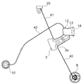
図1において、本発明の一実施形態を採用した自転車は軽快車であり、ダブルループ形のフレーム体2とフロントフォーク3とを有するフレーム1と、ハンドル部4と、駆動部5と、ブレーキ付きのダイナモハブ8が装着された前輪6と、内装変速ハブ10が装着された後輪7と、内装変速ハブ10を手元で操作するための変速操作部20と、変速操作部20の操作に応じて内装変速ハブ10を変速制御する変速制御ユニット12とを備えている。
【0027】
フレーム1のフレーム体2は、パイプを溶接して製作されたものである。フレーム体2には、サドル11や駆動部5を含む各部が取り付けられている。フロントフォーク3は、フレーム体2の前部に斜めに傾いた軸回りに揺動自在に装着されている。
【0028】
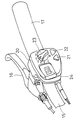
ハンドル部4は、フロントフォーク3の上部に固定されたハンドルステム14と、ハンドルステム14に固定されたハンドルバー15とを有している。ハンドルバー15の両端にはブレーキレバー16とグリップ17とが装着されている。右側のブレーキレバー16には変速操作部20が一体で形成されている。
【0029】
駆動部5は、フレーム体2の下部(ハンガー部)に設けられたギアクランク37と、ギアクランク37に掛け渡されたチェーン38と、内装変速ハブ10とを有している。内装変速ハブ10は、低速段(1速)、中速段(2速)、高速段(3速)の3つの変速段を有する3段変速の内装変速ハブであり、変速制御ユニット12に設けられたモータユニット29(図6)により3つの変速位置を取り得る。
【0030】
フロントフォーク3の先端に固定された前輪6のダイナモハブ8は、ローラ形の前ブレーキを装着可能なハブであり、内部に前輪6の回転により発電する交流発電機19(図6)を有している。
【0031】
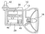
変速制御ユニット12は、図2に示すように、ダイナモハブ8内の交流発電機19に電気配線40を介して電気的に接続されている。また、変速制御ユニット12は、変速操作部20にも電気配線41を介して電気的に接続されている。さらに変速制御ユニット12は、変速ケーブル42を介して内装変速ハブ10に機械的に連結されている。変速制御ユニット12は、図3及び図4に示すように、フロントフォーク3の途中のランプスティ3aに装着されたランプケース13と、ランプケース13に収納されたモータユニット29及び回路ユニット30とを有している。
【0032】
モータユニット29は、図3及び図4に示すように、変速モータ45と、変速モータ45により3つの変速位置に移動するケーブル動作部46と、ケーブル動作部46の変速位置を検出する動作位置センサ47(図6)とを有している。このケーブル動作部46に変速ケーブル42の一端が連結されている。
【0033】
回路ユニット30は、図6に示すように、CPU,RAM,ROM,I/Oインターフェースからなるマイクロコンピュータを含む変速制御部25を備えている。なお、図中太線はたとえば1A程度の電流線を、実線は5mA程度の電流線をそれぞれ示し、破線は信号線を示している。
【0034】
変速制御部25は、変速操作部20の操作に応じて内装変速ハブ10を速度に応じて自動変速制御するとともに、変速操作部20に設けられた液晶表示部24の表示制御を行う。また、ランプケース13に一体で装着されたランプ18を周囲の状況が所定の明るさ以下になると点灯し、所定の明るさを超えると消灯するランプ制御を行う。変速制御部25には、変速操作部20に設けられた操作ダイヤル23及び操作ボタン21,22を含む操作スイッチ26と、液晶表示部24と、ランプ18を制御するための照度センサとしての光センサ36と、交流発電機19からの出力により速度信号を生成するためのダイナモ波形成形回路34とが接続されている。また、変速制御部25には、充電制御回路33と蓄電素子32とオートライト回路35とが省電力回路31を介して接続されている。さらに、モータドライバ28とモータユニット29の動作位置センサ47と他の入出力部とが接続されている。
【0035】
変速操作部20は、図5に示すように、下部に左右に並べて配置された2つの操作ボタン21,22と、操作ボタン21,22の上方に配置された操作ダイヤル23と、操作ダイヤル23の左方に配置された液晶表示部24とを有している。
【0036】
操作ボタン21,22は、三角形状の押しボタンである。左側の操作ボタン21は低速段から中速段、中速段から高速段への手動変速を行うためのボタンであり、右側の操作ボタン22は高速段から中速段、中速段から低速段への手動変速を行うためのボタンである。操作ダイヤル23は、モード1からモード7までの7つの自動変速モードと手動モードとを切り換えるためのダイヤルであり、8つの停止位置M,A1〜A7を有している。ここでモード1からモード7までの7つの自動変速モードは、交流発電機19からからの車速信号により内装変速ハブ10を自動変速するモードであり、手動変速モードは、操作ボタン21,22の操作により内装変速ハブ10を変速するモードである。
【0037】
なお、7つの自動変速モードでは、上り変速(低速側から高速側への変速)及び下り変速(高速側から低速側への変速)とにおいて、変速タイミング、具体的には変速時の速度を変えて自動変速するものである。このときの変速しきい値を図7に示す。ここでは、モード1からモード7にいくに従い上り及び下り変速の変速タイミングが徐々に早くなる。すなわち、モード7では、最も低速で変速しモード1では最も高速で変速する。通常はモード4くらいで変速させるのが好ましく。上り坂ではその斜度に応じてモードを選べばよい。
【0038】
液晶表示部24には、現在の走行速度も表示されるとともに、変速時には操作された変速段が表示される。
【0039】
省電力回路31は、自転車が停止しているときの電力消費を抑えるために設けられたものである。省電力回路31には、蓄電素子32で蓄えられた電力が供給される。省電力回路31は、変速制御部25、モータドライバ28、充電制御回路33及びオートライト回路35に接続され、それらに蓄電素子32で蓄えられた動作用の電力を供給するとともに、自転車停止時にそれらへの電力の供給を遮断する。省電力回路31には、交流発電機19からの信号が入力されており、この信号により自転車が停止しているか否かを判断する。このような省電力回路31を設けることにより蓄電素子32に蓄えられた電力の無駄な消耗を抑えることができる。
【0040】
蓄電素子32は、たとえば大容量コンデンサからなり、交流発電機19から出力され、充電制御回路33で整流された直流電力を蓄える。蓄電素子32で蓄えられた1mAの電流は省電力回路31を介して変速制御部25、モータドライバ28、充電制御回路33及びオートライト回路35に供給される。モータドライバ28には蓄電素子32で蓄えられた1Aの電流も直接供給される。なお、蓄電素子32をコンデンサに代えてニッケル・カドニウム電池やリチウムイオン電池やニッケル水素電池などの二次電池で構成してもよい。
【0041】
モータドライバ28は、変速モータ45を位置決め制御する。モータドライバ28は、省電力回路31から供給された1mAの電流で動作し、蓄電素子32から供給された1Aの電流を位置決め用に制御して変速モータ45に供給する。
【0042】
充電制御回路33はたとえば半波整流回路で構成され、交流発電機19から出力された交流電流をたとえば1Aと5mAの直流電流に整流する。
【0043】
ダイナモ波形成形回路34は、交流発電機19から出力された交流電流から速度信号を生成する。すなわちサインカーブの交流信号をたとえば半周期分抽出し、それをシュミット回路等の適宜の波形成形回路を通し、速度に応じたパルス信号を生成する。
【0044】
オートライト回路35は、光センサ36からの検出出力より変速制御部25から出力されるオンオフ信号により動作し、交流発電機19から出力された1Aの電流をランプ18に供給・遮断する。これにより照度が所定以下になるとランプ18が自動的に点灯し、所定の照度を超えると消灯する。
【0045】
このように構成された変速制御ユニット12では、変速操作部20で選択された自動変速モード又は手動変速モードで内装変速ハブ10が変速制御される。具体的には、たとえば自動変速モードのモード4が選択されると、図7に示すように、車速が12.7km/hになると、1速から2速に上り変速される。さらに17.1km/hになると3速に上り変速される。一方、その後車速が15.6km/hに下がると2速に下り変速され、さらに11.5km/hを下がると1速に下り変速される。ここでは、変速時のチャタリングを防止するために上り変速のタイミングと下り変速のタイミングとを下り側を低くしている、このような変速時に、交流発電機19からの交流信号により車速を検出しているので、車速を車輪1回転当たり細かく得ることができ、従来のものより実際の車速の変化にリアルタイムに追随して変速がなされる。
【0046】
一方、車輪が回転すると、省電力回路31がそのことを検出して変速制御部25や充電制御回路33等に制御動作用の電力を供給する。この結果、変速制御部25が動作を開始し、液晶表示部24やモータドライバ28やオートライト回路35や充電制御回路33が制御される。そして、交流発電機19からの電力が蓄電素子32に充電される。また、ダイナモ波形成形回路34から車速信号が変速制御部25に与えられる。車輪が停止すると省電力回路31がそれを検出して制御用の電力の供給を遮断する。これにより、停止時に無駄な電力を消費しなくなる。このため、停止時に蓄電素子32が消耗しなくなる。
【0047】
ここでは、蓄電素子32を設けて交流発電機19からの電力を蓄え、その電力により変速制御部25を含む各部を動作させているので、電池の交換や充電作業が不要になる。また、電池残量の管理や予備の電池を持ち歩く必要がなくなり、電源に関わる煩わしい作業を行うことなく自動変速を行えるようになる。
【0048】
しかも、交流発電機19から出力された交流信号に基づき車速を検出し、その検出された車速により変速制御している。交流発電機は一般に複数の磁極を有しているので、交流発電機からはこの磁極数と車速とに関連する周波数からなる交流信号が出力される。このため、通常自転車で用いられるような、たとえば車輪に付けた磁石を検出する速度センサから得られる速度信号に比べて1回転当たり多くのパルス信号を交流信号から得ることができる。したがって車速を1回転の間に細かく検出することができ、リアルタイムで高精度の変速制御を行える。また、交流発電機19からの交流信号に基づき制御しているので、従来のように車輪の近くに変速制御ユニット12を配置する必要がなくなり、変速制御ユニット12の装着位置が制限されない。
【0049】
また、従来、昼間は使用していなかった交流発電機19の電力を変速制御ユニット12で有効に利用できるようになる。
【0050】
〔他の実施形態〕
(a) 前記実施形態では、変速操作部20に液晶表示部を設けて変速段や車速を表示するようにしたが、表示を行わなくともよい。
【0051】
(b) 前記実施形態では、変速操作部を設けたが、変速操作部を設けなくてもよい。すなわち、たとえば、クランクに作用するトルクを検出して車速とトルクとの関係により複数の自動変速モードのいずれかを自動的に選択するようにしてもよい。また、自動変速モードを1種類に固定してもよい。
【0052】
(c) 前記実施形態では、変速用のモータユニットを変速制御ユニット内に設けたが、図8に示すように、変速用のモータや動作位置センサ等のモータユニット229を変速装置110側に配置してもよい。この場合、変速制御ユニット212と変速装置110とを変速ケーブルではなく電気配線48で結ぶだけでよい。
【0053】
(d) 前記実施形態では、発電効率がよく走行抵抗が少ないダイナモハブ8に設けられた交流発電機からの電力を利用したが、車輪のリムやタイヤに接触して発電する交流発電機からの電力を利用してもよい。
【0054】
(e) 前記実施形態では内装変速ハブを変速制御しているが制御対象の変速装置は内装式に限定されず外装式でもよい。外装式の場合、リアディレーラに限定されずフロントディレーラを制御してもよい。また、モータユニットを二つ設けて両方を制御してもよい。
【0055】
【発明の効果】
本発明によれば、蓄電手段を設けて交流発電機からの電力を蓄え、その電力により変速制御手段を動作させているので、電池の交換や充電作業が不要になる。また、電池残量の管理や予備の電池を持ち歩く必要がなくなり、電源に関わる煩わしい作業を行うことなく自動変速を行えるようになる。また、ランプをケースに内蔵しているので、逆にいうとランプのケース内に変速制御手段や蓄電手段を格納することができる。このため、通常ランプはフレームの前部に装着されるので走行の邪魔にならない位置に装置を配置できる。また、ランプへの配線も不要になるので防水絶縁構造をさらに高めることができる。
【0056】
しかも、交流発電機から出力された交流信号に基づき変速制御している。交流発電機は一般に複数の磁極を有しているので、交流発電機からはこの磁極数と車速とに関連する周波数からなる交流信号が出力される。このため、通常自転車で用いられるような、たとえば車輪に付けた磁石を検出する速度センサから得られる速度信号に比べて1回転当たり多くのパルス信号を交流信号から得ることができる。したがって車速を1回転の間に細かく検出することができ、リアルタイムで高精度の変速制御を行える。また、交流発電機からの交流信号に基づき制御しているので、従来のように車輪の近くに装置を配置する必要がなくなり、装置の装着位置が制限されない。
【図面の簡単な説明】
【図1】本発明の一実施形態1を採用した自転車の側面図。
【図2】内装変速ハブと変速制御ユニットとダイナモハブとの接続関係を示す模式図。
【図3】変速制御ユニットの側面断面図。
【図4】変速制御ユニットの平面断面図。
【図5】変速操作部の斜視図。
【図6】変速制御ユニットの構成を示すブロック図。
【図7】各自動変速モード毎の変速タイミングを示すテーブル
【図8】他の実施形態の図2に相当する図。
【符号の説明】
1 フレーム
8 ダイナモハブ
10 内装変速ハブ
12 変速制御ユニット
13 ランプケース
18 ランプ
19 交流発電機
20 変速操作部
23 操作ダイヤル
24 液晶表示部
25 変速制御部
29 モータユニット
32 蓄電素子
33 充電制御回路
34 ダイナモ波形成形回路
35 オートライト回路
36 光センサ
42 変速ケーブル
45 電動モータ
46 ケーブル動作部[0001]
TECHNICAL FIELD OF THE INVENTION
The present invention relates to a shift control device, and more particularly to a shift control device for a bicycle that is mounted on a bicycle on which an alternator and a transmission having a plurality of gears are mounted, and controls the transmission to one of a plurality of gears. .
[0002]
[Prior art]
Bicycle transmissions include an internal transmission that is built into the rear wheel hub and an external transmission that has a derailleur that bridges the chain over either the multi-stage sprocket or the sprocket mounted on the rear wheel hub or crank. Each of the transmissions has a plurality of shift speeds, and is conventionally operated via a shift cable from a shift operation unit mounted on a bicycle frame to switch to any one of the plurality of shift speeds.
[0003]
Recently, an automatic transmission unit capable of performing automatic transmission by operating a transmission cable by an electric motor has been developed. Such an automatic transmission unit is set to, for example, a high speed stage having a large speed increase ratio during high speed traveling, and a low speed stage having a small speed increasing ratio and lightly moving at low speed traveling. In order to realize this operation, the automatic transmission unit includes an electric motor for operating the transmission cable, a control unit including, for example, a microcomputer for controlling the electric motor to shift, a vehicle speed detection unit for detecting the vehicle speed of the bicycle, A case that accommodates these components and is mounted on a bicycle frame. A primary battery such as a dry battery or a secondary battery such as a nickel - cadmium battery is used as a power supply for power supply of the electric motor and the control unit. When the battery is exhausted, replacement or charging by a charging device is performed. . The vehicle speed is detected by detecting a magnet provided on the wheel of the bicycle by a sensor provided in the case, and outputs a vehicle speed signal of one pulse per rotation to the control unit. The control unit switches the gear according to the input vehicle speed signal.
[0004]
[Problems to be solved by the invention]
In the above-described conventional configuration, since electric power is supplied from a power supply to an electric motor that consumes relatively large electric power, the battery is drastically consumed depending on the frequency of shifting. When the power supply is exhausted, the battery must be replaced or charged, and replacement and charging are troublesome. In addition, gear shifting cannot be performed if the battery runs out. Therefore, it is necessary to constantly check the remaining battery level and prepare a spare battery, and the power supply management work is troublesome.
[0005]
Further, in the above-described conventional configuration, the vehicle speed of the bicycle is detected by an output from a sensor that outputs one pulse per one rotation of the wheel, and shift control is performed at the detected speed. For this reason, the detected vehicle speed and the actual vehicle speed may deviate by a maximum of one rotation of the wheel, and a response delay may occur, and shift control may not be performed with high accuracy.
[0006]
Further, since the sensor for detecting the vehicle speed is provided in the case, the shift control device must be arranged near the wheels, and the mounting position of the device is limited.
[0007]
SUMMARY OF THE INVENTION It is an object of the present invention to provide a bicycle shift control device capable of performing an automatic shift without performing a troublesome operation related to a power supply.
[0008]
Another object of the present invention is to enable a bicycle shift control device to precisely detect a vehicle speed and perform a highly accurate shift control in real time.
[0009]
Still another object of the present invention is to provide a bicycle shift control device that does not limit the mounting position of the device.
[0010]
[Means for Solving the Problems]
A bicycle shift control device according to a first aspect of the present invention is a device that is mounted on a bicycle equipped with an alternator and a transmission having a plurality of gears, and controls the transmission to one of a plurality of gears. The vehicle includes a power storage unit, a shift control unit, a case, and a lamp . The power storage means is a means capable of storing power from the AC generator. The shift control unit is a unit that operates with the electric power stored in the power storage unit and controls the transmission to one of a plurality of shift speeds based on an AC signal from the AC generator. The case stores power storage means and shift control means and can be mounted on a bicycle. The lamp is built into the case.
[0011]
In this shift control device, when the case is mounted on a bicycle frame, a steering wheel, or the like, and the power of the AC generator is supplied to the power storage means, the power is stored and the shift control means is operated by the stored power. The shift control means switches the shift speed of the transmission based on an AC signal from the AC generator. Thus, for example, during high-speed traveling, a high-speed stage with a large speed increase ratio is set, and at low-speed traveling, a low-speed stage with a small speed increase ratio and lightly stiffened.
[0012]
Here, the power storage means is provided to store the power from the AC generator, and the power is used to operate the shift control means, so that there is no need to replace or charge the battery. In addition, there is no need to manage the remaining battery level or carry a spare battery, and automatic shifting can be performed without performing cumbersome operations related to the power supply. Further, since the lamp is built in the case, conversely, the speed change control means and the power storage means can be stored in the case of the lamp. For this reason, since the lamp is usually mounted on the front part of the frame, the device can be arranged at a position where it does not hinder the traveling. In addition, since wiring to the lamp is not required, the waterproof insulation structure can be further enhanced.
[0013]
In addition, the shift control is performed based on the AC signal output from the AC generator. Since an AC generator generally has a plurality of magnetic poles, the AC generator outputs an AC signal having a frequency related to the number of magnetic poles and the vehicle speed. For this reason, more pulse signals per rotation can be obtained from the AC signal than a speed signal obtained from a speed sensor that detects a magnet attached to a wheel, for example, which is usually used in a bicycle. Therefore, the vehicle speed can be finely detected during one rotation, and high-accuracy shift control can be performed in real time. Further, since the control is performed based on the AC signal from the AC generator, it is not necessary to arrange the device near the wheels as in the related art, and the mounting position of the device is not limited.
[0014]
According to a second aspect of the present invention, there is provided the bicycle shift control device according to the first aspect, wherein the shift control means generates a speed signal corresponding to the vehicle speed of the bicycle from the AC signal and controls the shift device based on the generated speed signal. . In this case, the speed change of the transmission can be accurately controlled by the speed signal generated from the AC signal.
[0015]
A bicycle shift control device according to a third aspect of the present invention is the device according to the first or second aspect, further comprising a display unit that displays a bicycle speed based on the generated speed signal. In this case, since the vehicle speed is displayed, the user can travel while checking the speed.
[0016]
According to a fourth aspect of the present invention, there is provided a shift control device for a bicycle according to any one of the first to third aspects, wherein the shift device has an electric motor for performing a shift operation, and the shift control means controls the electric motor. In this case, since the transmission control means controls the electric motor in the transmission, it is only necessary to connect the transmission and the transmission control device with a signal cable and a power cable. For this reason, the work of arranging the transmission cable becomes unnecessary.
[0017]
A bicycle transmission control device according to a fifth aspect of the present invention is the bicycle transmission control device according to any one of the first to third aspects, wherein the bicycle transmission control device is built in a case, and is operated by an electric motor for causing the transmission to perform a shift operation and the electric motor. Further, there is provided a cable operating means connected by the following, and the shift control means controls the electric motor. In this case, since the electric motor is provided in the case, it is possible to perform automatic shift control of a conventional manual transmission that performs manual shifting. Further, since electrical wiring is not required between the transmission and the transmission, the waterproof insulation structure is facilitated.
[0018]
A bicycle shift control device according to a sixth aspect of the present invention is the bicycle shift control device according to any one of the first to fifth aspects, wherein the lamp can be turned on by electric power supplied from the AC generator. In this case, since the lamp is directly lit by the electric power from the AC generator instead of the electric power stored in the electric storage means, the influence of the blinking of the lamp on the electric storage means is less likely to occur.
[0019]
A bicycle shift control device according to a seventh aspect of the present invention is the bicycle shift control device according to any one of the first to sixth aspects, further comprising a ramp control unit for controlling a ramp. In this case, the lamp can be automatically turned on and off according to day and night, and the amount of light can be adjusted. Also, electric power can be transferred to the power storage means as needed.
[0020]
The bicycle shift control device according to an eighth aspect of the present invention is the bicycle shift control device according to any one of the first to seventh aspects, further comprising an illuminance detection unit for detecting illuminance, and the lamp control unit turns on and off the lamp based on the illuminance detection result. Control. In this case, since the lamp can be turned on and off depending on the illuminance, the lamp can be automatically turned on and off according to day and night.
[0021]
A bicycle shift control device according to a ninth aspect of the present invention is the bicycle shift control device according to any one of the first to eighth aspects, further comprising a shift operation unit having an automatic shift mode selection unit capable of selecting a plurality of types of shift timings of the transmission, The shift control means switches a plurality of shift speeds at the selected shift timing. In this case, the gear can be shifted at different timings during sports running, running on an uphill, or the like, so that automatic shifting can be performed in accordance with running conditions.
[0022]
[0023]
Invention bicycle shift control device according to 1 1, in the device according to any of the
[0024]
Invention bicycle shift control device according to 1 2, in the device according to any of the
[0025]
Invention bicycle shift control device according to 1 3, in the device according to any of the
[0026]
BEST MODE FOR CARRYING OUT THE INVENTION
〔Constitution〕
In FIG. 1, a bicycle adopting an embodiment of the present invention is a light vehicle, and includes a
[0027]
The
[0028]
The
[0029]
The
[0030]
The
[0031]
The speed
[0032]
As shown in FIGS. 3 and 4, the
[0033]
As shown in FIG. 6, the
[0034]
The
[0035]
As shown in FIG. 5, the speed
[0036]
The
[0037]
In the seven automatic shift modes, the shift timing, specifically, the speed at the time of shifting is changed between an upshift (shifting from a low speed side to a high speed side) and a downshifting (shifting from a high speed side to a low speed side). The automatic speed change is performed. FIG. 7 shows the shift threshold value at this time. Here, the shift timing of the upshift and the downshift is gradually advanced from
[0038]
The liquid
[0039]
The power saving circuit 31 is provided to suppress power consumption when the bicycle is stopped. The power stored in the
[0040]
[0041]
The
[0042]
The
[0043]
The dynamo
[0044]
The
[0045]
In the
[0046]
On the other hand, when the wheels rotate, the power saving circuit 31 detects that fact and supplies power for the control operation to the
[0047]
Here, since the electric power from the
[0048]
In addition, the vehicle speed is detected based on the AC signal output from the
[0049]
Further, the power of the
[0050]
[Other embodiments]
(A) In the above-described embodiment, the
[0051]
( B ) In the above embodiment, the shift operation unit is provided, but the shift operation unit may not be provided. That is, for example, one of a plurality of automatic shift modes may be automatically selected based on the relationship between the vehicle speed and the torque by detecting the torque acting on the crank. Further, the automatic transmission mode may be fixed to one type.
[0052]
( C ) In the above embodiment, the shift motor unit is provided in the shift control unit. However, as shown in FIG. 8 , a
[0053]
( D ) In the above-described embodiment, the power from the AC generator provided in the
[0054]
( E ) In the above embodiment, the speed of the internal transmission hub is controlled, but the transmission to be controlled is not limited to the internal transmission type but may be an external transmission type. In the case of the exterior type, the front derailleur may be controlled without being limited to the rear derailleur. Alternatively, two motor units may be provided to control both.
[0055]
【The invention's effect】
According to the present invention, since the electric power from the AC generator is stored by providing the electric storage means and the shift control means is operated by the electric power, there is no need to replace or charge the battery. In addition, there is no need to manage the remaining battery level or carry a spare battery, and automatic shifting can be performed without performing cumbersome operations related to the power supply. Further, since the lamp is built in the case, conversely, the speed change control means and the power storage means can be stored in the case of the lamp. For this reason, since the lamp is usually mounted on the front part of the frame, the device can be arranged at a position where it does not hinder the traveling. In addition, since wiring to the lamp is not required, the waterproof insulation structure can be further enhanced.
[0056]
In addition, the shift control is performed based on the AC signal output from the AC generator. Since an AC generator generally has a plurality of magnetic poles, the AC generator outputs an AC signal having a frequency related to the number of magnetic poles and the vehicle speed. For this reason, more pulse signals per rotation can be obtained from the AC signal than a speed signal obtained from a speed sensor that detects a magnet attached to a wheel, for example, which is usually used in a bicycle. Therefore, the vehicle speed can be finely detected during one rotation, and high-accuracy shift control can be performed in real time. Further, since the control is performed based on the AC signal from the AC generator, it is not necessary to arrange the device near the wheels as in the related art, and the mounting position of the device is not limited.
[Brief description of the drawings]
FIG. 1 is a side view of a bicycle employing a first embodiment of the present invention.
FIG. 2 is a schematic diagram showing a connection relationship among an internal transmission hub, a transmission control unit, and a dynamo hub.
FIG. 3 is a side sectional view of a transmission control unit.
FIG. 4 is a plan sectional view of a transmission control unit.
FIG. 5 is a perspective view of a speed change operation unit.
FIG. 6 is a block diagram showing a configuration of a shift control unit.
FIG. 7 is a table showing shift timing for each automatic shift mode. FIG. 8 is a diagram corresponding to FIG. 2 of another embodiment.
[Explanation of symbols]
1
Claims (13)
前記交流発電機からの電力を蓄積可能な蓄電手段と、
前記蓄電手段に蓄積された電力により動作するとともに、前記交流発電機からの交流信号に基づき前記変速装置を前記複数の変速段のいずれかに制御する変速制御手段と、
前記蓄電手段と前記変速制御手段とを格納し、前記自転車に装着可能なケースと、
前記ケースに内蔵された照明用のランプと、
を備えた自転車用変速制御装置。A shift control device for a bicycle, which is mounted on a bicycle equipped with an alternator and a transmission having a plurality of gears, and controls the transmission to any one of the plurality of gears,
Power storage means capable of storing power from the AC generator,
A shift control unit that operates with the electric power stored in the power storage unit and controls the transmission to one of the plurality of shift speeds based on an AC signal from the AC generator;
A case which stores the power storage means and the shift control means, and which can be mounted on the bicycle;
A lamp for lighting built in the case,
Gearshift control device with bicycle
前記変速制御手段は前記電動モータを制御する、請求項1から3のいずれか1項に記載の自転車用変速制御装置。The transmission has an electric motor for performing a shift operation,
Said shift control means controls the electric motor, bicycle shift control device according to any one of claims 1 to 3.
前記変速制御手段は前記電動モータを制御する、請求項1から3のいずれか1項に記載の自転車用変速制御装置。An electric motor built in the case for operating the transmission to perform a shifting operation, and a cable operating means operated by the electric motor and connected to the transmission by a shift cable;
Said shift control means controls the electric motor, bicycle shift control device according to any one of claims 1 to 3.
前記ランプ制御手段は前記照度検出結果により前記ランプを点灯・消灯制御する、請求項7に記載の自転車用変速制御装置。Further provided is illuminance detection means for detecting illuminance,
The bicycle shift control device according to claim 7 , wherein the lamp control unit controls turning on and off of the lamp based on the illuminance detection result.
前記変速制御手段は、前記選択された変速タイミングで前記複数の変速段を切り換える、請求項1から8のいずれか1項に記載の自転車用変速制御装置。A shift operation unit having an automatic shift mode selection unit capable of selecting a plurality of shift timings of the transmission;
Said shift control means, said switching the plurality of shift speeds in the selected shift timing, bicycle shift control device according to any one of claims 1 to 8.
Priority Applications (7)
| Application Number | Priority Date | Filing Date | Title |
|---|---|---|---|
| JP2001198420A JP3573723B2 (en) | 2001-06-29 | 2001-06-29 | Gear change control device for bicycle |
| US10/179,564 US6959939B2 (en) | 2001-06-29 | 2002-06-24 | Electronic bicycle shift control device |
| EP02014440A EP1270397B1 (en) | 2001-06-29 | 2002-06-28 | Electronic bicycle shift control device |
| CNB021244898A CN100457543C (en) | 2001-06-29 | 2002-06-28 | Variable speed controller for bicycle |
| TW091114687A TW581738B (en) | 2001-06-29 | 2002-06-28 | Speed-changing control unit for bicycle |
| DE60217228T DE60217228T2 (en) | 2001-06-29 | 2002-06-28 | Electrically controlled transmission shifting device for a bicycle |
| CZ20022274A CZ20022274A3 (en) | 2001-06-29 | 2002-06-28 | Device for controlling gear shifting in a bicycle |
Applications Claiming Priority (1)
| Application Number | Priority Date | Filing Date | Title |
|---|---|---|---|
| JP2001198420A JP3573723B2 (en) | 2001-06-29 | 2001-06-29 | Gear change control device for bicycle |
Publications (2)
| Publication Number | Publication Date |
|---|---|
| JP2003011879A JP2003011879A (en) | 2003-01-15 |
| JP3573723B2 true JP3573723B2 (en) | 2004-10-06 |
Family
ID=19035875
Family Applications (1)
| Application Number | Title | Priority Date | Filing Date |
|---|---|---|---|
| JP2001198420A Expired - Fee Related JP3573723B2 (en) | 2001-06-29 | 2001-06-29 | Gear change control device for bicycle |
Country Status (7)
| Country | Link |
|---|---|
| US (1) | US6959939B2 (en) |
| EP (1) | EP1270397B1 (en) |
| JP (1) | JP3573723B2 (en) |
| CN (1) | CN100457543C (en) |
| CZ (1) | CZ20022274A3 (en) |
| DE (1) | DE60217228T2 (en) |
| TW (1) | TW581738B (en) |
Cited By (1)
| Publication number | Priority date | Publication date | Assignee | Title |
|---|---|---|---|---|
| US20210245835A1 (en) * | 2020-02-06 | 2021-08-12 | Tektro Technology Corporation | Method for controlling derailleur in low battery remaining capacity |
Families Citing this family (27)
| Publication number | Priority date | Publication date | Assignee | Title |
|---|---|---|---|---|
| JP2005053363A (en) | 2003-08-05 | 2005-03-03 | Shimano Inc | Hollow structural component part bicycle |
| JP2002281691A (en) * | 2001-03-22 | 2002-09-27 | Shimano Inc | Circuit for charging bicycle and detecting its speed |
| JP3740097B2 (en) | 2002-07-10 | 2006-01-25 | 株式会社シマノ | Bicycle display system |
| DE20214095U1 (en) * | 2002-09-12 | 2004-02-12 | Plim Cooperation Ag | Bicycle Front Light |
| JP3703809B2 (en) * | 2003-02-25 | 2005-10-05 | 株式会社シマノ | Bicycle automatic transmission control device |
| JP3793168B2 (en) * | 2003-04-01 | 2006-07-05 | 株式会社シマノ | Bicycle power supply device and bicycle power supply method |
| DE10327456A1 (en) * | 2003-06-18 | 2005-01-13 | Busch & Müller KG | Method for controlling a lighting unit of a bicycle and circuit for the delay-induced operation of a lighting unit of a bicycle |
| JP3994081B2 (en) | 2003-10-28 | 2007-10-17 | 株式会社シマノ | Bicycle shift control device |
| JP2005225426A (en) | 2004-02-16 | 2005-08-25 | Shimano Inc | Bicycle lighting system and bicycle display device that can be fitted thereto |
| JP2005271750A (en) * | 2004-03-25 | 2005-10-06 | Sanyo Electric Co Ltd | Remote controller for bicycle generator |
| JP4145839B2 (en) | 2004-06-29 | 2008-09-03 | 株式会社シマノ | Bicycle shifting system and bicycle |
| US7176750B2 (en) * | 2004-08-23 | 2007-02-13 | Atmel Corporation | Method and apparatus for fast power-on of the band-gap reference |
| JP4164071B2 (en) | 2005-02-04 | 2008-10-08 | シマノ シンガポール ピーティーイー.リミテッド. | Claw pole generator and bicycle power generation hub |
| JP4141453B2 (en) | 2005-03-16 | 2008-08-27 | 株式会社シマノ | Bicycle power supply |
| US7363873B2 (en) | 2006-02-21 | 2008-04-29 | Shimano Inc. | Bicycle shift control device with light structure |
| JP4168061B2 (en) | 2006-04-28 | 2008-10-22 | 株式会社シマノ | Bicycle lighting system |
| US7547021B2 (en) * | 2006-09-22 | 2009-06-16 | Nirve Sports, Ltd. | Propelled bicycle with automatic transmission |
| US7503547B2 (en) * | 2006-10-04 | 2009-03-17 | Shimano Inc. | Bicycle electric cable tensioning assembly |
| JP2008278614A (en) * | 2007-04-27 | 2008-11-13 | Shimano Inc | Power supply device and electric system for bicycle |
| US10207772B2 (en) | 2011-01-28 | 2019-02-19 | Paha Designs, Llc | Gear transmission and derailleur system |
| US9033833B2 (en) | 2011-01-28 | 2015-05-19 | Paha Designs, Llc | Gear transmission and derailleur system |
| US9327792B2 (en) | 2011-01-28 | 2016-05-03 | Paha Designs, Llc | Gear transmission and derailleur system |
| CN202179824U (en) * | 2011-07-22 | 2012-04-04 | 北京美亚视景创恒科技有限公司 | Digital body-building equipment cluster system |
| JP2015027861A (en) * | 2013-07-05 | 2015-02-12 | 株式会社シマノ | Bicycle control system |
| JP5827376B1 (en) * | 2014-06-09 | 2015-12-02 | 株式会社シマノ | Power supply system, electric assist system, and electric speed change system |
| TWI644831B (en) * | 2017-07-26 | 2018-12-21 | 鄭仲瑞 | Bicycle self-powered automatic transmission |
| US11414151B2 (en) * | 2019-09-06 | 2022-08-16 | Shimano Inc. | Operating system for human-powered vehicle |
Family Cites Families (42)
| Publication number | Priority date | Publication date | Assignee | Title |
|---|---|---|---|---|
| US3904920A (en) * | 1973-04-12 | 1975-09-09 | Ronald A Griffith | Safety lighting system |
| JPS5320244A (en) | 1976-08-05 | 1978-02-24 | Mitsubishi Electric Corp | Automatic transmission for light vehicle |
| DK160359C (en) * | 1986-11-14 | 1991-08-12 | Herluf Jakob Larsen | LIGHTING FOR A BIKE |
| US5059158A (en) * | 1990-05-08 | 1991-10-22 | E.B.T., Inc. | Electronic transmission control system for a bicycle |
| JP2628799B2 (en) | 1991-03-26 | 1997-07-09 | ブリヂストンサイクル株式会社 | Bicycle automatic lighting equipment |
| IT1252262B (en) * | 1991-11-18 | 1995-06-08 | Catene Calibrate Regina | AUTOMATED TRANSMISSION FOR BICYCLE |
| US5213548A (en) * | 1992-03-02 | 1993-05-25 | Colbert Ralph G | Gear shifting system for derailleur equipped bicycle |
| JP2569372Y2 (en) | 1992-03-13 | 1998-04-22 | 株式会社キャットアイ | Battery case mounting device |
| US5436810A (en) * | 1992-08-13 | 1995-07-25 | Vistalite, Inc. | Portable headlamp |
| CN2159936Y (en) * | 1992-11-26 | 1994-03-30 | 杭州助动车厂 | Control box for multifunction power-assisted bicycle |
| CA2132442C (en) * | 1993-01-22 | 1999-02-23 | Seizo Nakamura | Instantaneous phase detecting circuit and clock recovery signal generating circuit incorporated in differential demodulator |
| JP2941636B2 (en) * | 1994-03-01 | 1999-08-25 | 株式会社日立製作所 | Vehicle alternator rotor |
| JPH08228463A (en) | 1994-11-08 | 1996-09-03 | Koji Fukumoto | Generator-illuminator for vehicle |
| JPH08133150A (en) | 1994-11-10 | 1996-05-28 | Sanyo Electric Co Ltd | Headlamp for bicycle |
| FR2727376B1 (en) * | 1994-11-25 | 1997-01-17 | Seb Sa | ELECTRONIC DERAILLEUR |
| JPH08175460A (en) | 1994-12-28 | 1996-07-09 | Akebono Brake Ind Co Ltd | Transmission for bicycle |
| JP3556001B2 (en) * | 1995-01-18 | 2004-08-18 | 株式会社シマノ | Bicycle generator interior hub and bicycle lighting device |
| CN1050812C (en) * | 1995-03-28 | 2000-03-29 | 王维德 | Method and device for bicycle automatic gearshift with computer control |
| IT1276417B1 (en) * | 1995-06-07 | 1997-10-31 | Campagnolo Srl | "SPEED CHANGE DEVICE FOR BICYCLES WITH ELECTRONIC CONTROL" |
| US5599244A (en) * | 1995-08-14 | 1997-02-04 | Ethington; Russell A. | Automatic transmission shifter for velocipedes |
| JPH0976982A (en) | 1995-09-11 | 1997-03-25 | Yamaha Motor Co Ltd | Power-assisted vehicle |
| US5690410A (en) * | 1995-10-23 | 1997-11-25 | Lin; Tzu-Lung | Light device for a bicycle |
| JPH1081275A (en) | 1996-09-10 | 1998-03-31 | Shimano Inc | Lighting system for bicycle |
| JP3284060B2 (en) * | 1996-09-20 | 2002-05-20 | 株式会社シマノ | Bicycle shift control method and shift control device thereof |
| DE19642605A1 (en) * | 1996-10-16 | 1998-04-23 | Frank Bergler | Gear changing device for bicycle |
| US6047230A (en) * | 1997-02-27 | 2000-04-04 | Spencer; Marc D. | Automatic bicycle transmission |
| JP3231006B2 (en) * | 1997-08-28 | 2001-11-19 | 株式会社シマノ | Gear change control device for bicycle |
| JPH1170863A (en) | 1997-08-29 | 1999-03-16 | Bridgestone Cycle Co | Speed control device for bicycle |
| JP3423590B2 (en) * | 1997-09-12 | 2003-07-07 | 本田技研工業株式会社 | Light unit with external power supply terminal |
| JPH11129960A (en) | 1997-11-04 | 1999-05-18 | Honda Motor Co Ltd | Battery unit for motor-assisted vehicle |
| US6017140A (en) * | 1997-11-18 | 2000-01-25 | Chou; Ming-Fu | Multifunctional bicycle lamp |
| CN1187707A (en) * | 1997-12-08 | 1998-07-15 | 龚德明 | Bicycle driving generator device and generator |
| JPH11301546A (en) | 1998-04-22 | 1999-11-02 | Matsushita Electric Ind Co Ltd | Lighting unit for bicycle |
| JPH11301547A (en) | 1998-04-24 | 1999-11-02 | Bridgestone Cycle Co | Tail lamp controller for bicycle |
| US6407663B1 (en) * | 1998-06-26 | 2002-06-18 | Polaris Industries Inc. | Multi-function display meter system for a motorcycle |
| JP2000016363A (en) | 1998-07-01 | 2000-01-18 | Matsushita Electric Ind Co Ltd | Bicycle lamp having burglar alarm |
| JP2000289682A (en) | 1999-04-12 | 2000-10-17 | Suzuki Motor Corp | Electric-motor-assisted bicycle |
| JP2001039380A (en) | 1999-07-28 | 2001-02-13 | Matsushita Electric Ind Co Ltd | Automatic gearshift operating device for bicycle |
| US6453262B1 (en) * | 1999-12-24 | 2002-09-17 | Shimano, Inc. | Method and apparatus for selecting a processing mode for a bicycle computer |
| JP3396655B2 (en) * | 2000-02-29 | 2003-04-14 | 株式会社シマノ | Bicycle power supply |
| US6367833B1 (en) * | 2000-09-13 | 2002-04-09 | Shimano, Inc. | Automatic shifting control device for a bicycle |
| JP3842966B2 (en) * | 2000-09-26 | 2006-11-08 | 本田技研工業株式会社 | Speedometer mounting structure for motorcycles |
-
2001
- 2001-06-29 JP JP2001198420A patent/JP3573723B2/en not_active Expired - Fee Related
-
2002
- 2002-06-24 US US10/179,564 patent/US6959939B2/en not_active Expired - Fee Related
- 2002-06-28 CN CNB021244898A patent/CN100457543C/en not_active Expired - Fee Related
- 2002-06-28 DE DE60217228T patent/DE60217228T2/en not_active Expired - Lifetime
- 2002-06-28 TW TW091114687A patent/TW581738B/en not_active IP Right Cessation
- 2002-06-28 EP EP02014440A patent/EP1270397B1/en not_active Expired - Fee Related
- 2002-06-28 CZ CZ20022274A patent/CZ20022274A3/en unknown
Cited By (2)
| Publication number | Priority date | Publication date | Assignee | Title |
|---|---|---|---|---|
| US20210245835A1 (en) * | 2020-02-06 | 2021-08-12 | Tektro Technology Corporation | Method for controlling derailleur in low battery remaining capacity |
| US11952079B2 (en) * | 2020-02-06 | 2024-04-09 | Tektro Technology Corporation | Method for controlling derailleur in low battery remaining capacity |
Also Published As
| Publication number | Publication date |
|---|---|
| JP2003011879A (en) | 2003-01-15 |
| EP1270397A3 (en) | 2005-03-30 |
| CN1394787A (en) | 2003-02-05 |
| DE60217228D1 (en) | 2007-02-15 |
| CZ20022274A3 (en) | 2003-02-12 |
| US6959939B2 (en) | 2005-11-01 |
| EP1270397A2 (en) | 2003-01-02 |
| DE60217228T2 (en) | 2007-10-04 |
| US20030001357A1 (en) | 2003-01-02 |
| TW581738B (en) | 2004-04-01 |
| EP1270397B1 (en) | 2007-01-03 |
| CN100457543C (en) | 2009-02-04 |
Similar Documents
| Publication | Publication Date | Title |
|---|---|---|
| JP3573723B2 (en) | Gear change control device for bicycle | |
| JP3727315B2 (en) | Bicycle power supply | |
| US7119668B2 (en) | Illumination-controlled bicycle devices | |
| USRE43562E1 (en) | Bicycle shift control apparatus that prevents undesirable chain angles | |
| US7311322B2 (en) | Bicycle control apparatus that sets a bicycle transmission to a predetermined gear ratio | |
| US7288038B2 (en) | Bicycle shift control apparatus with preferential shifting | |
| US6959941B2 (en) | Bicycle shift control apparatus that selectively restricts speed stages | |
| JP3793168B2 (en) | Bicycle power supply device and bicycle power supply method | |
| US7119707B2 (en) | Circuit for providing electrical current to a bicycle device | |
| JP3793143B2 (en) | Bicycle electronic control device | |
| JP4065275B2 (en) | Bicycle shifting system |
Legal Events
| Date | Code | Title | Description |
|---|---|---|---|
| A131 | Notification of reasons for refusal |
Free format text: JAPANESE INTERMEDIATE CODE: A131 Effective date: 20040120 |
|
| A521 | Written amendment |
Free format text: JAPANESE INTERMEDIATE CODE: A523 Effective date: 20040317 |
|
| TRDD | Decision of grant or rejection written | ||
| A01 | Written decision to grant a patent or to grant a registration (utility model) |
Free format text: JAPANESE INTERMEDIATE CODE: A01 Effective date: 20040622 |
|
| A61 | First payment of annual fees (during grant procedure) |
Free format text: JAPANESE INTERMEDIATE CODE: A61 Effective date: 20040629 |
|
| R150 | Certificate of patent or registration of utility model |
Free format text: JAPANESE INTERMEDIATE CODE: R150 |
|
| FPAY | Renewal fee payment (event date is renewal date of database) |
Free format text: PAYMENT UNTIL: 20080709 Year of fee payment: 4 |
|
| FPAY | Renewal fee payment (event date is renewal date of database) |
Free format text: PAYMENT UNTIL: 20080709 Year of fee payment: 4 |
|
| FPAY | Renewal fee payment (event date is renewal date of database) |
Free format text: PAYMENT UNTIL: 20090709 Year of fee payment: 5 |
|
| FPAY | Renewal fee payment (event date is renewal date of database) |
Free format text: PAYMENT UNTIL: 20090709 Year of fee payment: 5 |
|
| FPAY | Renewal fee payment (event date is renewal date of database) |
Free format text: PAYMENT UNTIL: 20100709 Year of fee payment: 6 |
|
| FPAY | Renewal fee payment (event date is renewal date of database) |
Free format text: PAYMENT UNTIL: 20110709 Year of fee payment: 7 |
|
| FPAY | Renewal fee payment (event date is renewal date of database) |
Free format text: PAYMENT UNTIL: 20110709 Year of fee payment: 7 |
|
| FPAY | Renewal fee payment (event date is renewal date of database) |
Free format text: PAYMENT UNTIL: 20120709 Year of fee payment: 8 |
|
| FPAY | Renewal fee payment (event date is renewal date of database) |
Free format text: PAYMENT UNTIL: 20120709 Year of fee payment: 8 |
|
| FPAY | Renewal fee payment (event date is renewal date of database) |
Free format text: PAYMENT UNTIL: 20130709 Year of fee payment: 9 |
|
| R250 | Receipt of annual fees |
Free format text: JAPANESE INTERMEDIATE CODE: R250 |
|
| R250 | Receipt of annual fees |
Free format text: JAPANESE INTERMEDIATE CODE: R250 |
|
| R250 | Receipt of annual fees |
Free format text: JAPANESE INTERMEDIATE CODE: R250 |
|
| R250 | Receipt of annual fees |
Free format text: JAPANESE INTERMEDIATE CODE: R250 |
|
| R250 | Receipt of annual fees |
Free format text: JAPANESE INTERMEDIATE CODE: R250 |
|
| LAPS | Cancellation because of no payment of annual fees |