EP1270397B1 - Electronic bicycle shift control device - Google Patents
Electronic bicycle shift control device Download PDFInfo
- Publication number
- EP1270397B1 EP1270397B1 EP02014440A EP02014440A EP1270397B1 EP 1270397 B1 EP1270397 B1 EP 1270397B1 EP 02014440 A EP02014440 A EP 02014440A EP 02014440 A EP02014440 A EP 02014440A EP 1270397 B1 EP1270397 B1 EP 1270397B1
- Authority
- EP
- European Patent Office
- Prior art keywords
- shift control
- lamp
- shift
- control element
- bicycle
- Prior art date
- Legal status (The legal status is an assumption and is not a legal conclusion. Google has not performed a legal analysis and makes no representation as to the accuracy of the status listed.)
- Expired - Fee Related
Links
Images


Classifications
-
- B—PERFORMING OPERATIONS; TRANSPORTING
- B62—LAND VEHICLES FOR TRAVELLING OTHERWISE THAN ON RAILS
- B62M—RIDER PROPULSION OF WHEELED VEHICLES OR SLEDGES; POWERED PROPULSION OF SLEDGES OR SINGLE-TRACK CYCLES; TRANSMISSIONS SPECIALLY ADAPTED FOR SUCH VEHICLES
- B62M9/00—Transmissions characterised by use of an endless chain, belt, or the like
- B62M9/04—Transmissions characterised by use of an endless chain, belt, or the like of changeable ratio
- B62M9/06—Transmissions characterised by use of an endless chain, belt, or the like of changeable ratio using a single chain, belt, or the like
- B62M9/10—Transmissions characterised by use of an endless chain, belt, or the like of changeable ratio using a single chain, belt, or the like involving different-sized wheels, e.g. rear sprocket chain wheels selectively engaged by the chain, belt, or the like
- B62M9/12—Transmissions characterised by use of an endless chain, belt, or the like of changeable ratio using a single chain, belt, or the like involving different-sized wheels, e.g. rear sprocket chain wheels selectively engaged by the chain, belt, or the like the chain, belt, or the like being laterally shiftable, e.g. using a rear derailleur
-
- B—PERFORMING OPERATIONS; TRANSPORTING
- B62—LAND VEHICLES FOR TRAVELLING OTHERWISE THAN ON RAILS
- B62M—RIDER PROPULSION OF WHEELED VEHICLES OR SLEDGES; POWERED PROPULSION OF SLEDGES OR SINGLE-TRACK CYCLES; TRANSMISSIONS SPECIALLY ADAPTED FOR SUCH VEHICLES
- B62M25/00—Actuators for gearing speed-change mechanisms specially adapted for cycles
- B62M25/08—Actuators for gearing speed-change mechanisms specially adapted for cycles with electrical or fluid transmitting systems
Definitions
- the present invention is directed to bicycles and, more particularly, to an electronic shift control device for a bicycle transmission.
- Bicycle transmissions include internal transmissions and external transmissions.
- Internal transmissions ordinarily include a planetary gear mechanism fitted in the rear wheel hub.
- External transmissions ordinarily have a multiple sprocket cassette mounted on the rear wheel hub or crank, and a derailleur guides a chain among the multiple sprockets.
- a shift control cable is connected to the transmission and to a manually operated shift controller mounted to the bicycle frame, and the rider operates the shift controller to select a desired transmission gear.
- automatic bicycle transmissions which automatically shift the transmission to higher gear ratios when the bicycle is traveling at high speeds and which automatically shift the transmission to lower gear ratios when the bicycle is traveling at low speeds.
- Such automatic transmissions usually are equipped with an electric motor for operating the shift control cable, a speed sensor for sensing bicycle speed, a control element containing a microcomputer for controlling the electric motor in response to bicycle speed, and a case mounted to the bicycle frame for containing these components.
- US 5,865,454 which constitutes the closest prior art discloses an electronically controlled speed change device for bicycles having an automatic mode of operation shifting at the request of the cyclist for increase or decrease of the speed ratio, the chain among a plurality of shifting positions.
- the electrical power for the electrical components e.g. the motor, is provided by a rechargeable battery recharged by a dynamo mounted to one of the wheels of the bicycle.
- Dry cells and other primary cells, or nickel-cadmium and other secondary batteries are used to supply power to the electric motor, control element, etc..
- battery consumption may be heavy due to the relatively high power consumption of the electric motor. Batteries must be replaced or recharged when consumed, thus requiring time-consuming operations for the replacement or recharging.
- Another drawback is the need to constantly check remaining battery power and prepare reserve batteries, since shifting cannot be performed once the batteries are consumed.
- the speed sensor ordinarily is mounted for detecting the passage of a magnet attached to the bicycle wheel, and a speed signal pulse is communicated to the control element for each wheel rotation.
- the control element shifts the bicycle transmission in response to the speed signal pulses. Since the speed sensor outputs one pulse per wheel revolution, the calculated bicycle speed and the actual bicycle speed may differ by up to one wheel rotation. Since the control unit operates in response to these speed signals, there is a delayed response that can make high-precision shifting control impossible. Furthermore, if the speed sensor is mounted in the case together with the other components, then the case must be disposed near the bicycle wheel, thus limiting possible device mounting positions.
- a bicycle shift control device is adapted to be mounted to a bicycle equipped with an alternating current generator and a shifting device having a plurality of speed steps.
- the shift control device includes a power storage unit adapted to store electrical power from the alternating current generator; a shift control element operatively coupled for receiving electrical power from the power storage unit and for providing shift control signals for controlling the operation of the shifting device; and a case adapted to be mounted to the bicycle, wherein the case houses both the power storage unit and the shift control element.
- a wave shaping circuit is provided that converts a signal from the alternating current generator to a speed signal, wherein the shift control element provides the shift control signals in response to the speed signal. Since speed signals derived from the generator can be produced more than once per wheel revolution, the shift control element can operate with greater precision than known shift control elements.
- a lamp a lamp control circuit and/or a light sensor may be mounted in the case, alone or in any combination and the shift control element may operate with all such components.
- a display may be provided to display various operating parameters.
- a mode selection switch may be provided to select among various operating modes, and manual shift switches or other components may be provided to allow manual operation of the shift control element and other functions. If desired, such additional components may be housed separately from the case.
- Fig. 1 is a side view of a bicycle that includes a particular embodiment of an electronic bicycle transmission according to the present invention.
- This bicycle is a recreational bicycle comprising a frame 1 having a double-loop frame body 2 formed from welded tubes, a front fork 3 rotatably mounted to the frame body 2, a handle component 4, a drive component 5, a front wheel 6 on which a dynamo hub 8 with brakes is mounted, a rear wheel 7 on which an internal shifting hub 10 is mounted, a saddle 11, a shift control unit 12 to control shifting of the internal shifting hub 10, and a shift controller 20 for manually operating the shift control unit 12.
- the handle component 4 comprises a handle stem 14, fastened to the upper part of the front fork 3, and a handlebar 15 fastened to the handle stem 14.
- Brake levers 16 and grips 17 are mounted on both ends of the handlebar 15.
- the shift controller 20 is integrated with the right-side brake lever 16.
- the drive component 5 comprises a crank 37, mounted on the lower part (bottom bracket component) of the frame body 2, and a chain 38 that engages the crank 37 and the internal shifting hub 10.
- the internal shifting hub 10 is capable of producing three speed steps, including a low speed step (speed 1), an intermediate speed step (speed 2), and a high speed step (speed 3). These three speed steps can be selected by means of a motor unit 29 (Fig. 3) in the shift control unit 12.
- the dynamo hub 8 of the front wheel 6 can be fitted with a roller-type front brake, and it houses an alternating current generator 19 (Fig.
- the shift control unit 12 is electrically connected to the alternating current generator 19 housed in the dynamo hub 8 by electrical wiring 40, and it is electrically connected to the shift controller 20 by electrical wiring 41.
- the shift control unit 12 is mechanically connected to the internal shifting hub 10 by a shift control cable 42.
- the shift control unit 12 comprises a lamp case 13 mounted to a lamp stay 3a located midway along the front fork 3 for housing a lamp 18.
- the motor unit 29 and a circuit unit 30 are housed in the lamp case 13.
- the motor unit 29 comprises a shifting motor 45, a cable operating component 46 which moves into three shifting positions by means of the shifting motor 45, and a position sensor 47 (Fig. 6) to detect the shift position of the cable operating component 46.
- One end of the shift control cable 42 is connected to this cable operating component 46.
- the circuit unit 30 comprises a shift control element 25 (Fig. 6) containing a microcomputer comprising a CPU, RAM, ROM, and an I/O interface.
- the shift controller 20 comprises two operating buttons 21 and 22 in the form of triangular pushbuttons disposed next to each other, an operating dial 23 disposed above the operating buttons 21 and 22, and a liquid crystal display component 24 disposed to the left of the operating dial 23.
- the operating button 21 on the left side is for manually shifting from the low speed step to the intermediate speed step and to the high speed step.
- the operating button 22 on the right side is for manually shifting from the high speed step to the intermediate speed step and to the low speed step.
- the operating dial 23 is used for switching between a manual mode (M) and seven automatic shifting modes (A1 - A7) using eight detent positions.
- the seven automatic shifting modes A1 - A7 are modes for automatically shifting the internal shifting hub 10 according to a bicycle speed signal derived from the alternating current generator 19 in a manner described below.
- the seven automatic shifting modes are designed to allow shift timing (i.e., the speed at which shifting will occur) to be automatically changed during upshifting (shifting from low speed to high speed) or downshifting (shifting from high speed to low speed).
- the shift timings for the various modes are shown in Fig. 7.
- the upward and downward shift timings gradually decrease from mode 1 through mode 7 such that mode 1 shifts at the highest speed, and mode 7 shifts at the lowest speed. It is usually preferable to set the shift controller to about mode 4. For climbing hills, a mode may be set according to the steepness of the hill.
- the hub When automatic shifting mode 4 is selected, for example, the hub is upshifted from speed 1 to speed 2 when the bicycle speed reaches 12.7 km/h. Similarly, the hub is upshifted to speed 3 when the bicycle speed reaches 17.1 km/h. On the other hand, when the bicycle speed later falls to 15.6 km/h, the hub is downshifted to speed 2, and again downshifted to speed 1 when the bicycle speed falls to 11.5 km/h. Between upshift timing and downshift timing, downshift timing is set as the lower of the two to prevent chattering during shifting.
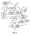
- Fig. 6 is a block diagram illustrating the structure of the shift control device. Heavy lines in Fig. 6 indicate lines carrying about 1 A of current, solid lines indicate lines carrying about 5 mA of current, and dotted lines indicate signal lines. Shift control element 25 is operatively coupled to an operating switch 26 (which schematically represents the operating dial 23 and operating buttons 21 and 22 in the shift controller 20), to the liquid crystal display component 24, to a light sensor 36 (illumination sensor) for controlling the lamp 18, to a dynamo waveform shaping circuit 34 that generates a speed signal derived from the output of the alternating current generator 19, to a motor driver 28, to the active position sensor 47 of the motor unit 29, and to other input/output components.
- an operating switch 26 which schematically represents the operating dial 23 and operating buttons 21 and 22 in the shift controller 20
- a light sensor 36 for controlling the lamp 18
- a dynamo waveform shaping circuit 34 that generates a speed signal derived from the output of the alternating current generator 19, to a motor driver 28, to the active position sensor
- Shift control element 25 automatically controls shifting of the internal shifting hub 10 according to travel speed, and it controls the information displayed on the liquid crystal display component 24 disposed in the shift controller 20. In this embodiment, the current travel speed and the speed step activated during shifting are displayed together on the liquid crystal display component 24.
- the shift control element 25 also controls the lamp 18 by turning it on when surrounding light conditions fall below a certain prescribed brightness, and by turning it off when surrounding light conditions are above the prescribed brightness.
- a charge control circuit 33, a power storage element 32, and an auto light circuit 35 are operatively coupled to the shift control element 25 via a power-saving circuit 31.
- a signal from the alternating current generator 19 is input to the power-saving circuit 31, and it is determined based on this signal whether or not the bicycle is stopped.
- the power saving circuit 31 supplies the shift control element 25, the motor driver 28, the charge control circuit 33 and the auto light circuit 35 with electrical power stored by the power storage element 32 when the bicycle is moving for the normal operation of these components, and it interrupts the supply of electrical power to these components when the bicycle is stopped to avoid needless expenditure of electrical power stored by the power storage element 32.
- Motor driver 28 operates on a 1 mA current supplied by the power-saving circuit 31, and it controls a 1A current supplied by the power storage element 32 to operate the shifting motor 45.
- the charge control circuit 33 comprises, for example, a half-wave rectifier circuit that rectifies an alternating current output from the alternating current generator 19 to, for example, 1A and 5 mA direct currents.
- the power storage element 32 comprises, for example, a high-capacity capacitor that stores the direct current power that is output from the charge control circuit 33.
- the power storage element 32 also may comprise secondary batteries such as nickel cadmium batteries, lithium ion batteries, nickel-metal hydride batteries, etc., in lieu of a capacitor.
- the dynamo waveform shaping circuit 34 forms a speed signal from the alternating current output from the alternating current generator 19. More specifically, a half-cycle is extracted from a sine wave alternating current signal, passed through a Schmitt circuit or other appropriate waveform shaping circuit, and formed into a pulse signal corresponding to speed. Shift control element 25 uses this signal to control the automatic shifting of the internal shifting hub 10.
- the auto light circuit 35 supplies or interrupts the 1A current output from the alternating current generator 19 to the lamp 18 in response to on/off signal output from the shift control element 25.
- Shift control element 25 generates these signal based on the signals from the light sensor 36 in such a manner that the lamp 18 is switched on automatically when light levels fall below a prescribed limit, and it is switched off when light levels exceed the prescribed limit.
- lamp 18 is operated from the alternating current generator 19 so that the current draw is less apt to adversely affect the power storage element 32, but this is not necessary.
- Battery replacement and recharging are unnecessary because the power storage element 32 stores electrical power from the alternating current generator 19, and components such as the shift control element 25 are operated using this electrical power. Monitoring remaining battery power and carrying along spare batteries also become unnecessary, and shifting can be done automatically without performing the cumbersome procedures required by conventional power sources.
- the electrical power from the alternating current generator 19, which conventionally is not employed in the daytime, can be put to effective use in the shift control unit 12.
- bicycle speed is detected based on the alternating current signal output from the alternating current generator 19, and shifting is controlled according to the detected bicycle speed.
- alternating current generators generally have a plurality of circumferentially disposed magnetic poles
- the alternating current generator outputs an alternating current signal with a frequency related to the bicycle speed and the number of magnetic poles. Consequently, it is possible to obtain a larger number of signal pulses from the alternating current signal during each wheel rotation in comparison with a speed signal obtainable, for example, from a conventional speed sensor that detects a magnet mounted to the bicycle wheel. Therefore, the bicycle speed can be accurately detected within the space of one wheel rotation, and shifting can be controlled in real time with high precision. Furthermore, since shifting is controlled based on the alternating current signal from the alternating current generator 19, it is no longer necessary to dispose the shift control unit 12 in the vicinity of the bicycle wheel. No limitation is placed on the mounting position of the shift control unit 12.
- a shift control unit 112 may also be constructed using a case 121 of a shift controller 120.
- a lamp 118 and shift control unit 112 may be connected using electrical wiring 43.
- the case 121 is mounted on handlebar 15 in the vicinity of the handle stem 14, and a display component 124 and an operating dial 122 are positioned such that they are exposed to the outside. Circuit units and motor units are housed internally.
- a currently existing lamp can be used as the lamp 118, and a unit for automatic shifting can be mounted as a modification to an existing three speed bicycle.
- a shift controller was included in the aforementioned embodiments, but the shift controller may be omitted in some applications.
- torque acting on the crank could be detected, and an automatic shifting mode could be selected automatically from among a plurality of modes according to the relationship between the torque and bicycle speed.
- a single automatic shifting mode could be established.
- a motor unit for shifting was placed within the shift control unit in the aforementioned embodiments.
- a shifting motor, an active position sensor, or another motor unit 229 may be disposed facing the shifting device 110 as shown in Fig. 10.
- the shift control element 212 and the shifting device 110 may be connected merely by using electrical wiring 48 rather than a shift control cable.
- the shifting device could comprise a derailleur, such as a front and/or rear derailleur. If desired, two motor units may be used for controlling each derailleur.
- the display 24 may be omitted.
- the size, shape, location or orientation of the various components may be changed as desired.
- Components that are shown directly connected or contacting each other may have intermediate structures disposed between them.
- the functions of one element may be performed by two, and vice versa.
- the structures and functions of one embodiment may be adopted in another embodiment. It is not necessary for all advantages to be present in a particular embodiment at the same time. Thus, the scope of the invention should not be limited by the specific structures disclosed or the apparent initial focus on a particular structure or feature.
Description
- The present invention is directed to bicycles and, more particularly, to an electronic shift control device for a bicycle transmission.
- Bicycle transmissions include internal transmissions and external transmissions. Internal transmissions ordinarily include a planetary gear mechanism fitted in the rear wheel hub. External transmissions ordinarily have a multiple sprocket cassette mounted on the rear wheel hub or crank, and a derailleur guides a chain among the multiple sprockets. In either case, a shift control cable is connected to the transmission and to a manually operated shift controller mounted to the bicycle frame, and the rider operates the shift controller to select a desired transmission gear.
- Recently, automatic bicycle transmissions have been developed which automatically shift the transmission to higher gear ratios when the bicycle is traveling at high speeds and which automatically shift the transmission to lower gear ratios when the bicycle is traveling at low speeds. Such automatic transmissions usually are equipped with an electric motor for operating the shift control cable, a speed sensor for sensing bicycle speed, a control element containing a microcomputer for controlling the electric motor in response to bicycle speed, and a case mounted to the bicycle frame for containing these components.
- For example US 5,865,454 which constitutes the closest prior art discloses an electronically controlled speed change device for bicycles having an automatic mode of operation shifting at the request of the cyclist for increase or decrease of the speed ratio, the chain among a plurality of shifting positions. The electrical power for the electrical components, e.g. the motor, is provided by a rechargeable battery recharged by a dynamo mounted to one of the wheels of the bicycle.
- Dry cells and other primary cells, or nickel-cadmium and other secondary batteries, are used to supply power to the electric motor, control element, etc.. Depending on the frequency of shifting, battery consumption may be heavy due to the relatively high power consumption of the electric motor. Batteries must be replaced or recharged when consumed, thus requiring time-consuming operations for the replacement or recharging. Another drawback is the need to constantly check remaining battery power and prepare reserve batteries, since shifting cannot be performed once the batteries are consumed.
- The speed sensor ordinarily is mounted for detecting the passage of a magnet attached to the bicycle wheel, and a speed signal pulse is communicated to the control element for each wheel rotation. The control element shifts the bicycle transmission in response to the speed signal pulses. Since the speed sensor outputs one pulse per wheel revolution, the calculated bicycle speed and the actual bicycle speed may differ by up to one wheel rotation. Since the control unit operates in response to these speed signals, there is a delayed response that can make high-precision shifting control impossible. Furthermore, if the speed sensor is mounted in the case together with the other components, then the case must be disposed near the bicycle wheel, thus limiting possible device mounting positions.
- The present invention as disclosed by the features of
independent claim 1 is directed to an electronically controlled bicycle transmission that is superior to known electronically controlled bicycle transmissions. In one embodiment of the present invention, a bicycle shift control device is adapted to be mounted to a bicycle equipped with an alternating current generator and a shifting device having a plurality of speed steps. The shift control device includes a power storage unit adapted to store electrical power from the alternating current generator; a shift control element operatively coupled for receiving electrical power from the power storage unit and for providing shift control signals for controlling the operation of the shifting device; and a case adapted to be mounted to the bicycle, wherein the case houses both the power storage unit and the shift control element. A wave shaping circuit is provided that converts a signal from the alternating current generator to a speed signal, wherein the shift control element provides the shift control signals in response to the speed signal. Since speed signals derived from the generator can be produced more than once per wheel revolution, the shift control element can operate with greater precision than known shift control elements. - Other components may be mounted within the case to take advantage of the power supplied by the generator. For example, a lamp a lamp control circuit and/or a light sensor may be mounted in the case, alone or in any combination and the shift control element may operate with all such components. A display may be provided to display various operating parameters. A mode selection switch may be provided to select among various operating modes, and manual shift switches or other components may be provided to allow manual operation of the shift control element and other functions. If desired, such additional components may be housed separately from the case.
-
- Fig. 1 is a side view of a bicycle that includes a particular embodiment of an electronic bicycle transmission according to the present invention;
- Fig. 2 illustrates how the shift controller, the shift control unit, the generator and the transmission are coupled together;
- Fig. 3 is a side cross sectional view of the shift control unit shown in Fig. 2;
- Fig. 4 is a top cross sectional view of the shift control unit shown in Fig. 2;
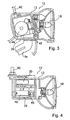
- Fig. 5 is a perspective view of the shift controller;
- Fig. 6 is a schematic block diagram of the shift control device;
- Fig. 7 is a series of tables showing the shifting characteristics for various automatic shifting modes;
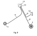
- Fig. 8 illustrates how the shift controller, the shift control unit, the generator and the transmission are coupled together in another embodiment of the present invention;
- Fig. 9 is a plan view of the shift controller and shift control unit shown in Fig. 8; and
- Fig. 10 illustrates how the shift controller, the shift control unit, the generator and the transmission are coupled together in another embodiment of the present invention.
- Fig. 1 is a side view of a bicycle that includes a particular embodiment of an electronic bicycle transmission according to the present invention. This bicycle is a recreational bicycle comprising a
frame 1 having a double-loop frame body 2 formed from welded tubes, afront fork 3 rotatably mounted to theframe body 2, ahandle component 4, adrive component 5, afront wheel 6 on which adynamo hub 8 with brakes is mounted, arear wheel 7 on which aninternal shifting hub 10 is mounted, asaddle 11, ashift control unit 12 to control shifting of theinternal shifting hub 10, and ashift controller 20 for manually operating theshift control unit 12. Thehandle component 4 comprises ahandle stem 14, fastened to the upper part of thefront fork 3, and ahandlebar 15 fastened to thehandle stem 14. Brake levers 16 andgrips 17 are mounted on both ends of thehandlebar 15. In this embodiment, theshift controller 20 is integrated with the right-side brake lever 16. Thedrive component 5 comprises acrank 37, mounted on the lower part (bottom bracket component) of theframe body 2, and achain 38 that engages thecrank 37 and theinternal shifting hub 10. Theinternal shifting hub 10 is capable of producing three speed steps, including a low speed step (speed 1), an intermediate speed step (speed 2), and a high speed step (speed 3). These three speed steps can be selected by means of a motor unit 29 (Fig. 3) in theshift control unit 12. Thedynamo hub 8 of thefront wheel 6 can be fitted with a roller-type front brake, and it houses an alternating current generator 19 (Fig. 6) that generates electricity in response to the rotation of thefront wheel 6. As shown in Fig. 2, theshift control unit 12 is electrically connected to the alternatingcurrent generator 19 housed in thedynamo hub 8 byelectrical wiring 40, and it is electrically connected to theshift controller 20 byelectrical wiring 41. Theshift control unit 12 is mechanically connected to theinternal shifting hub 10 by ashift control cable 42. - As shown in Figs. 3 and 4, the
shift control unit 12 comprises alamp case 13 mounted to alamp stay 3a located midway along thefront fork 3 for housing alamp 18. Themotor unit 29 and a circuit unit 30 are housed in thelamp case 13. Themotor unit 29 comprises a shiftingmotor 45, acable operating component 46 which moves into three shifting positions by means of the shiftingmotor 45, and a position sensor 47 (Fig. 6) to detect the shift position of thecable operating component 46. One end of theshift control cable 42 is connected to thiscable operating component 46. This arrangement facilitates waterproof construction, since no electrical wires are needed between theshift control unit 12 and theinternal shifting hub 10 orlamp 18. Furthermore, all of these components are mounted to the front of the bicycle, where they do not interfere with riding. The circuit unit 30 comprises a shift control element 25 (Fig. 6) containing a microcomputer comprising a CPU, RAM, ROM, and an I/O interface. - As shown in Fig. 5, the
shift controller 20 comprises twooperating buttons operating dial 23 disposed above theoperating buttons crystal display component 24 disposed to the left of theoperating dial 23. Theoperating button 21 on the left side is for manually shifting from the low speed step to the intermediate speed step and to the high speed step. Theoperating button 22 on the right side is for manually shifting from the high speed step to the intermediate speed step and to the low speed step. Theoperating dial 23 is used for switching between a manual mode (M) and seven automatic shifting modes (A1 - A7) using eight detent positions. - The seven automatic shifting modes A1 - A7 are modes for automatically shifting the
internal shifting hub 10 according to a bicycle speed signal derived from the alternatingcurrent generator 19 in a manner described below. The seven automatic shifting modes are designed to allow shift timing (i.e., the speed at which shifting will occur) to be automatically changed during upshifting (shifting from low speed to high speed) or downshifting (shifting from high speed to low speed). The shift timings for the various modes are shown in Fig. 7. The upward and downward shift timings gradually decrease frommode 1 throughmode 7 such thatmode 1 shifts at the highest speed, andmode 7 shifts at the lowest speed. It is usually preferable to set the shift controller to aboutmode 4. For climbing hills, a mode may be set according to the steepness of the hill. Whenautomatic shifting mode 4 is selected, for example, the hub is upshifted fromspeed 1 to speed 2 when the bicycle speed reaches 12.7 km/h. Similarly, the hub is upshifted to speed 3 when the bicycle speed reaches 17.1 km/h. On the other hand, when the bicycle speed later falls to 15.6 km/h, the hub is downshifted tospeed 2, and again downshifted to speed 1 when the bicycle speed falls to 11.5 km/h. Between upshift timing and downshift timing, downshift timing is set as the lower of the two to prevent chattering during shifting. - Fig. 6 is a block diagram illustrating the structure of the shift control device. Heavy lines in Fig. 6 indicate lines carrying about 1 A of current, solid lines indicate lines carrying about 5 mA of current, and dotted lines indicate signal lines.
Shift control element 25 is operatively coupled to an operating switch 26 (which schematically represents theoperating dial 23 andoperating buttons crystal display component 24, to a light sensor 36 (illumination sensor) for controlling thelamp 18, to a dynamowaveform shaping circuit 34 that generates a speed signal derived from the output of the alternatingcurrent generator 19, to amotor driver 28, to theactive position sensor 47 of themotor unit 29, and to other input/output components. -
Shift control element 25 automatically controls shifting of theinternal shifting hub 10 according to travel speed, and it controls the information displayed on the liquidcrystal display component 24 disposed in theshift controller 20. In this embodiment, the current travel speed and the speed step activated during shifting are displayed together on the liquidcrystal display component 24. Theshift control element 25 also controls thelamp 18 by turning it on when surrounding light conditions fall below a certain prescribed brightness, and by turning it off when surrounding light conditions are above the prescribed brightness. - A
charge control circuit 33, apower storage element 32, and anauto light circuit 35 are operatively coupled to theshift control element 25 via a power-saving circuit 31. A signal from the alternatingcurrent generator 19 is input to the power-saving circuit 31, and it is determined based on this signal whether or not the bicycle is stopped. The power saving circuit 31 supplies theshift control element 25, themotor driver 28, thecharge control circuit 33 and theauto light circuit 35 with electrical power stored by thepower storage element 32 when the bicycle is moving for the normal operation of these components, and it interrupts the supply of electrical power to these components when the bicycle is stopped to avoid needless expenditure of electrical power stored by thepower storage element 32.Motor driver 28 operates on a 1 mA current supplied by the power-saving circuit 31, and it controls a 1A current supplied by thepower storage element 32 to operate the shiftingmotor 45. - The
charge control circuit 33 comprises, for example, a half-wave rectifier circuit that rectifies an alternating current output from the alternatingcurrent generator 19 to, for example, 1A and 5 mA direct currents. Thepower storage element 32 comprises, for example, a high-capacity capacitor that stores the direct current power that is output from thecharge control circuit 33. Thepower storage element 32 also may comprise secondary batteries such as nickel cadmium batteries, lithium ion batteries, nickel-metal hydride batteries, etc., in lieu of a capacitor. - The dynamo
waveform shaping circuit 34 forms a speed signal from the alternating current output from the alternatingcurrent generator 19. More specifically, a half-cycle is extracted from a sine wave alternating current signal, passed through a Schmitt circuit or other appropriate waveform shaping circuit, and formed into a pulse signal corresponding to speed.Shift control element 25 uses this signal to control the automatic shifting of theinternal shifting hub 10. - The
auto light circuit 35 supplies or interrupts the 1A current output from the alternatingcurrent generator 19 to thelamp 18 in response to on/off signal output from theshift control element 25.Shift control element 25 generates these signal based on the signals from thelight sensor 36 in such a manner that thelamp 18 is switched on automatically when light levels fall below a prescribed limit, and it is switched off when light levels exceed the prescribed limit. In this embodiment,lamp 18 is operated from the alternatingcurrent generator 19 so that the current draw is less apt to adversely affect thepower storage element 32, but this is not necessary. - Battery replacement and recharging are unnecessary because the
power storage element 32 stores electrical power from the alternatingcurrent generator 19, and components such as theshift control element 25 are operated using this electrical power. Monitoring remaining battery power and carrying along spare batteries also become unnecessary, and shifting can be done automatically without performing the cumbersome procedures required by conventional power sources. The electrical power from the alternatingcurrent generator 19, which conventionally is not employed in the daytime, can be put to effective use in theshift control unit 12. - In addition, bicycle speed is detected based on the alternating current signal output from the alternating
current generator 19, and shifting is controlled according to the detected bicycle speed. Because alternating current generators generally have a plurality of circumferentially disposed magnetic poles, the alternating current generator outputs an alternating current signal with a frequency related to the bicycle speed and the number of magnetic poles. Consequently, it is possible to obtain a larger number of signal pulses from the alternating current signal during each wheel rotation in comparison with a speed signal obtainable, for example, from a conventional speed sensor that detects a magnet mounted to the bicycle wheel. Therefore, the bicycle speed can be accurately detected within the space of one wheel rotation, and shifting can be controlled in real time with high precision. Furthermore, since shifting is controlled based on the alternating current signal from the alternatingcurrent generator 19, it is no longer necessary to dispose theshift control unit 12 in the vicinity of the bicycle wheel. No limitation is placed on the mounting position of theshift control unit 12. - While the above is a description of various embodiments of the present invention, further modifications may be employed without departing from the present invention as claimed. For example, the
shift control unit 12 in the above embodiment was constructed using thelamp case 13, but as depicted in Figs. 8 and 9, ashift control unit 112 may also be constructed using acase 121 of ashift controller 120. In this instance, alamp 118 and shiftcontrol unit 112 may be connected usingelectrical wiring 43. In this embodiment, thecase 121 is mounted onhandlebar 15 in the vicinity of thehandle stem 14, and adisplay component 124 and anoperating dial 122 are positioned such that they are exposed to the outside. Circuit units and motor units are housed internally. In this embodiment, a currently existing lamp can be used as thelamp 118, and a unit for automatic shifting can be mounted as a modification to an existing three speed bicycle. - A shift controller was included in the aforementioned embodiments, but the shift controller may be omitted in some applications. For example, torque acting on the crank could be detected, and an automatic shifting mode could be selected automatically from among a plurality of modes according to the relationship between the torque and bicycle speed. Also, a single automatic shifting mode could be established.
- A motor unit for shifting was placed within the shift control unit in the aforementioned embodiments. However, if desired a shifting motor, an active position sensor, or another
motor unit 229 may be disposed facing the shiftingdevice 110 as shown in Fig. 10. In such a case, theshift control element 212 and the shiftingdevice 110 may be connected merely by usingelectrical wiring 48 rather than a shift control cable. - Electrical power from an alternating current generator with high generating efficiency and low running resistance in a
dynamo hub 8 was used in the aforementioned embodiments. However, if desired, electrical power generated by an alternating current generator in contact with the bicycle rim or tire may also be used. - An internal shifting hub was controllably shifted in the aforementioned embodiments, but the shifting device need not be mounted internally. The shifting device could comprise a derailleur, such as a front and/or rear derailleur. If desired, two motor units may be used for controlling each derailleur.
- If desired, the
display 24 may be omitted. The size, shape, location or orientation of the various components may be changed as desired. Components that are shown directly connected or contacting each other may have intermediate structures disposed between them. The functions of one element may be performed by two, and vice versa. The structures and functions of one embodiment may be adopted in another embodiment. It is not necessary for all advantages to be present in a particular embodiment at the same time. Thus, the scope of the invention should not be limited by the specific structures disclosed or the apparent initial focus on a particular structure or feature.
Claims (22)
- A bicycle shift control device (12, 112, 212) adapted to be mounted to a bicycle equipped with an alternating current generator (19) and a shifting device (10, 110) having a plurality of speed steps, wherein the shift control device (12, 112, 212) comprises:a power storage unit (32) adapted to store electrical power from the alternating current generator (19);a shift control element (25) operatively coupled for receiving electrical power from the power storage unit (32) and for providing shift control signals for controlling the operation of the shift control device (12, 112, 212); anda case (13, 121) adapted to be mounted to the bicycle, wherein the case (13, 121) characterized in thatsaid case (13, 121) houses both the power storage unit (32) and the shift control element (25); andsaid bicycle shift control device (12, 112, 212) further comprises a wave shaping circuit (34) that converts a signal from the alternating current generator (19) to a speed signal, wherein the shift control element (25) provides the shift control signals in response to the speed signal.
- The device (12, 112, 212) according to claim 1 further comprising a display (24, 124), wherein the shift control element (25) displays a bicycle speed on the display (24, 124) in response to the speed signal.
- The device (12) according to any of the preceding claims further comprising a motor driver circuit (28) operatively coupled for receiving the shift control signals from the shift control element (25).
- The device (12, 112, 212) according to claim 3 wherein the motor driver circuit (28) is housed within the case (13, 121).
- The device (12, 112, 212) according to claim 3 or 4 further comprising an electric motor (45) operatively coupled to the motor driver circuit (28) for controlling the shifting device (10, 110) in response to signals from the motor driver circuit (28).
- The device (12, 112, 212) according to claims 3 to 5 wherein the motor driver circuit (28) and the electric motor (45) both are housed within the case (13, 121).
- The device (12, 112, 212) according to any of the preceding claims further comprising a lamp (18, 118) housed within the case.
- The device (12, 112, 212) according to claim 7 wherein the lamp (18, 118) is adapted to receive electrical power from the alternating current generator (19).
- The device (12, 112, 212) according to claim 7 or 8 further comprising a lamp control circuit for controlling the operation of the lamp (18, 118).
- The device (12, 112, 212) according to claim 9 wherein the lamp control circuit is housed within the case (13, 121).
- The device (12, 112, 212) according to claims 7 to 10 further comprising a light sensor (36) for providing signals for controlling the operation of the lamp (18, 118) in response to ambient light.
- The device (12, 112, 212) according to claims 9 to 11 wherein the lamp control circuit and the light sensor (36) both are housed within the case (13, 121).
- The device (12, 112, 212) according to claims 9 to 11 wherein the shift control element (25) is operatively coupled to the light sensor (36) and to the lamp control circuit for providing signals to the lamp control circuit in response to signals from the light sensor (36).
- The device (12, 112, 212) according to any of the preceding claims further comprising: whereina lamp (18, 118); anda said lamp control circuit is operatively coupled to the lamp (18, 118) and to the shift control element (25) to control the operation of the lamp (18, 118) in response to signals from the shift control element (25).
- The device (12, 112, 212) according to any of the preceding claims further comprising a light sensor (36), wherein the lamp control circuit controls the operation of the lamp (18, 118) in response to signals from the light sensor (36).
- The device (12, 112, 212) according to any of the preceding claims wherein the shift control element (25) is programmed to operate in a plurality of automatic shift modes wherein, in each automatic shift mode, signals are provided to automatically operate the shifting device (10, 110) in response to predetermined parameters.
- The device (12, 112, 212) according to claim 16 further comprising a manually operated mode selector operatively coupled to the shift control element (25) for selecting among the plurality of automatic shift modes.
- The device (12, 112, 212) according to claim 16 or 17 further comprising a manually operated shift selector operatively coupled to the shift control element (25) for manually commanding the operation of the shifting device (10, 110).
- The device (12, 112, 212) according to claims 16 to 18 wherein the mode selector and the shift selector are housed separately from the shift control element (25).
- The device (12, 112, 212) according to any of the preceding claims wherein the power storage unit (32) comprises a capacitor.
- The device (12, 112, 212) according to any of the preceding claims wherein the power storage unit (32) comprises a battery.
- A bicycle display device (12, 112, 212) adapted to be mounted to a bicycle equipped with an alternating current generator (19), wherein the device comprises:The device (12, 112, 212) according to any of the preceding claims further comprisinga display (24, 124); anda control element operatively coupled for receiving electrical power from the alternating current generator (19) and for operating the display (24, 124) using the electrical power derived from the alternating current generator (19).
Applications Claiming Priority (2)
| Application Number | Priority Date | Filing Date | Title |
|---|---|---|---|
| JP2001198420A JP3573723B2 (en) | 2001-06-29 | 2001-06-29 | Gear change control device for bicycle |
| JP2001198420 | 2001-06-29 |
Publications (3)
| Publication Number | Publication Date |
|---|---|
| EP1270397A2 EP1270397A2 (en) | 2003-01-02 |
| EP1270397A3 EP1270397A3 (en) | 2005-03-30 |
| EP1270397B1 true EP1270397B1 (en) | 2007-01-03 |
Family
ID=19035875
Family Applications (1)
| Application Number | Title | Priority Date | Filing Date |
|---|---|---|---|
| EP02014440A Expired - Fee Related EP1270397B1 (en) | 2001-06-29 | 2002-06-28 | Electronic bicycle shift control device |
Country Status (7)
| Country | Link |
|---|---|
| US (1) | US6959939B2 (en) |
| EP (1) | EP1270397B1 (en) |
| JP (1) | JP3573723B2 (en) |
| CN (1) | CN100457543C (en) |
| CZ (1) | CZ20022274A3 (en) |
| DE (1) | DE60217228T2 (en) |
| TW (1) | TW581738B (en) |
Families Citing this family (28)
| Publication number | Priority date | Publication date | Assignee | Title |
|---|---|---|---|---|
| JP2005053363A (en) | 2003-08-05 | 2005-03-03 | Shimano Inc | Hollow structural component part bicycle |
| JP2002281691A (en) * | 2001-03-22 | 2002-09-27 | Shimano Inc | Circuit for charging bicycle and detecting its speed |
| JP3740097B2 (en) * | 2002-07-10 | 2006-01-25 | 株式会社シマノ | Bicycle display system |
| DE20214095U1 (en) * | 2002-09-12 | 2004-02-12 | Plim Cooperation Ag | Bicycle Front Light |
| JP3703809B2 (en) * | 2003-02-25 | 2005-10-05 | 株式会社シマノ | Bicycle automatic transmission control device |
| JP3793168B2 (en) * | 2003-04-01 | 2006-07-05 | 株式会社シマノ | Bicycle power supply device and bicycle power supply method |
| DE10327456A1 (en) * | 2003-06-18 | 2005-01-13 | Busch & Müller KG | Method for controlling a lighting unit of a bicycle and circuit for the delay-induced operation of a lighting unit of a bicycle |
| JP3994081B2 (en) | 2003-10-28 | 2007-10-17 | 株式会社シマノ | Bicycle shift control device |
| JP2005225426A (en) | 2004-02-16 | 2005-08-25 | Shimano Inc | Bicycle lighting system and bicycle display device that can be fitted thereto |
| JP2005271750A (en) * | 2004-03-25 | 2005-10-06 | Sanyo Electric Co Ltd | Remote controller for bicycle generator |
| JP4145839B2 (en) | 2004-06-29 | 2008-09-03 | 株式会社シマノ | Bicycle shifting system and bicycle |
| US7176750B2 (en) * | 2004-08-23 | 2007-02-13 | Atmel Corporation | Method and apparatus for fast power-on of the band-gap reference |
| JP4164071B2 (en) | 2005-02-04 | 2008-10-08 | シマノ シンガポール ピーティーイー.リミテッド. | Claw pole generator and bicycle power generation hub |
| JP4141453B2 (en) * | 2005-03-16 | 2008-08-27 | 株式会社シマノ | Bicycle power supply |
| US7363873B2 (en) | 2006-02-21 | 2008-04-29 | Shimano Inc. | Bicycle shift control device with light structure |
| JP4168061B2 (en) | 2006-04-28 | 2008-10-22 | 株式会社シマノ | Bicycle lighting system |
| US7547021B2 (en) * | 2006-09-22 | 2009-06-16 | Nirve Sports, Ltd. | Propelled bicycle with automatic transmission |
| US7503547B2 (en) * | 2006-10-04 | 2009-03-17 | Shimano Inc. | Bicycle electric cable tensioning assembly |
| JP2008278614A (en) * | 2007-04-27 | 2008-11-13 | Shimano Inc | Power supply device and electric system for bicycle |
| US9327792B2 (en) | 2011-01-28 | 2016-05-03 | Paha Designs, Llc | Gear transmission and derailleur system |
| US9033833B2 (en) | 2011-01-28 | 2015-05-19 | Paha Designs, Llc | Gear transmission and derailleur system |
| US10207772B2 (en) | 2011-01-28 | 2019-02-19 | Paha Designs, Llc | Gear transmission and derailleur system |
| CN202179824U (en) * | 2011-07-22 | 2012-04-04 | 北京美亚视景创恒科技有限公司 | Digital body-building equipment cluster system |
| JP2015027861A (en) * | 2013-07-05 | 2015-02-12 | 株式会社シマノ | Bicycle control system |
| JP5827376B1 (en) * | 2014-06-09 | 2015-12-02 | 株式会社シマノ | Power supply system, electric assist system, and electric speed change system |
| TWI644831B (en) * | 2017-07-26 | 2018-12-21 | 鄭仲瑞 | Bicycle self-powered automatic transmission |
| US11414151B2 (en) | 2019-09-06 | 2022-08-16 | Shimano Inc. | Operating system for human-powered vehicle |
| TWI716276B (en) * | 2020-02-06 | 2021-01-11 | 彥豪金屬工業股份有限公司 | Low battery power control method for bicycle derailleur |
Family Cites Families (42)
| Publication number | Priority date | Publication date | Assignee | Title |
|---|---|---|---|---|
| US3904920A (en) * | 1973-04-12 | 1975-09-09 | Ronald A Griffith | Safety lighting system |
| JPS5320244A (en) | 1976-08-05 | 1978-02-24 | Mitsubishi Electric Corp | Automatic transmission for light vehicle |
| DK160359C (en) * | 1986-11-14 | 1991-08-12 | Herluf Jakob Larsen | LIGHTING FOR A BIKE |
| US5059158A (en) * | 1990-05-08 | 1991-10-22 | E.B.T., Inc. | Electronic transmission control system for a bicycle |
| JP2628799B2 (en) | 1991-03-26 | 1997-07-09 | ブリヂストンサイクル株式会社 | Bicycle automatic lighting equipment |
| IT1252262B (en) * | 1991-11-18 | 1995-06-08 | Catene Calibrate Regina | AUTOMATED TRANSMISSION FOR BICYCLE |
| US5213548A (en) * | 1992-03-02 | 1993-05-25 | Colbert Ralph G | Gear shifting system for derailleur equipped bicycle |
| JP2569372Y2 (en) | 1992-03-13 | 1998-04-22 | 株式会社キャットアイ | Battery case mounting device |
| US5436810A (en) * | 1992-08-13 | 1995-07-25 | Vistalite, Inc. | Portable headlamp |
| CN2159936Y (en) * | 1992-11-26 | 1994-03-30 | 杭州助动车厂 | Control box for multifunction power-assisted bicycle |
| SG49146A1 (en) * | 1993-01-22 | 1998-05-18 | Oki Electric Ind Co Ltd | Instantaneous phase sensitive detector and generator for clock reproducing signal installed in delay detector |
| JP2941636B2 (en) * | 1994-03-01 | 1999-08-25 | 株式会社日立製作所 | Vehicle alternator rotor |
| JPH08228463A (en) | 1994-11-08 | 1996-09-03 | Koji Fukumoto | Generator-illuminator for vehicle |
| JPH08133150A (en) | 1994-11-10 | 1996-05-28 | Sanyo Electric Co Ltd | Headlamp for bicycle |
| FR2727376B1 (en) * | 1994-11-25 | 1997-01-17 | Seb Sa | ELECTRONIC DERAILLEUR |
| JPH08175460A (en) | 1994-12-28 | 1996-07-09 | Akebono Brake Ind Co Ltd | Transmission for bicycle |
| JP3556001B2 (en) * | 1995-01-18 | 2004-08-18 | 株式会社シマノ | Bicycle generator interior hub and bicycle lighting device |
| CN1050812C (en) * | 1995-03-28 | 2000-03-29 | 王维德 | Method and device for bicycle automatic gearshift with computer control |
| IT1276417B1 (en) * | 1995-06-07 | 1997-10-31 | Campagnolo Srl | "SPEED CHANGE DEVICE FOR BICYCLES WITH ELECTRONIC CONTROL" |
| US5599244A (en) * | 1995-08-14 | 1997-02-04 | Ethington; Russell A. | Automatic transmission shifter for velocipedes |
| JPH0976982A (en) | 1995-09-11 | 1997-03-25 | Yamaha Motor Co Ltd | Power-assisted vehicle |
| US5690410A (en) * | 1995-10-23 | 1997-11-25 | Lin; Tzu-Lung | Light device for a bicycle |
| JPH1081275A (en) | 1996-09-10 | 1998-03-31 | Shimano Inc | Lighting system for bicycle |
| JP3284060B2 (en) * | 1996-09-20 | 2002-05-20 | 株式会社シマノ | Bicycle shift control method and shift control device thereof |
| DE19642605A1 (en) * | 1996-10-16 | 1998-04-23 | Frank Bergler | Gear changing device for bicycle |
| US6047230A (en) * | 1997-02-27 | 2000-04-04 | Spencer; Marc D. | Automatic bicycle transmission |
| JP3231006B2 (en) * | 1997-08-28 | 2001-11-19 | 株式会社シマノ | Gear change control device for bicycle |
| JPH1170863A (en) | 1997-08-29 | 1999-03-16 | Bridgestone Cycle Co | Speed control device for bicycle |
| JP3423590B2 (en) * | 1997-09-12 | 2003-07-07 | 本田技研工業株式会社 | Light unit with external power supply terminal |
| JPH11129960A (en) | 1997-11-04 | 1999-05-18 | Honda Motor Co Ltd | Battery unit for motor-assisted vehicle |
| US6017140A (en) * | 1997-11-18 | 2000-01-25 | Chou; Ming-Fu | Multifunctional bicycle lamp |
| CN1187707A (en) * | 1997-12-08 | 1998-07-15 | 龚德明 | Bicycle driving generator device and generator |
| JPH11301546A (en) | 1998-04-22 | 1999-11-02 | Matsushita Electric Ind Co Ltd | Lighting unit for bicycle |
| JPH11301547A (en) | 1998-04-24 | 1999-11-02 | Bridgestone Cycle Co | Tail lamp controller for bicycle |
| US6407663B1 (en) * | 1998-06-26 | 2002-06-18 | Polaris Industries Inc. | Multi-function display meter system for a motorcycle |
| JP2000016363A (en) | 1998-07-01 | 2000-01-18 | Matsushita Electric Ind Co Ltd | Bicycle lamp having burglar alarm |
| JP2000289682A (en) | 1999-04-12 | 2000-10-17 | Suzuki Motor Corp | Electric-motor-assisted bicycle |
| JP2001039380A (en) | 1999-07-28 | 2001-02-13 | Matsushita Electric Ind Co Ltd | Automatic gearshift operating device for bicycle |
| US6453262B1 (en) * | 1999-12-24 | 2002-09-17 | Shimano, Inc. | Method and apparatus for selecting a processing mode for a bicycle computer |
| JP3396655B2 (en) * | 2000-02-29 | 2003-04-14 | 株式会社シマノ | Bicycle power supply |
| US6367833B1 (en) * | 2000-09-13 | 2002-04-09 | Shimano, Inc. | Automatic shifting control device for a bicycle |
| JP3842966B2 (en) * | 2000-09-26 | 2006-11-08 | 本田技研工業株式会社 | Speedometer mounting structure for motorcycles |
-
2001
- 2001-06-29 JP JP2001198420A patent/JP3573723B2/en not_active Expired - Fee Related
-
2002
- 2002-06-24 US US10/179,564 patent/US6959939B2/en not_active Expired - Fee Related
- 2002-06-28 TW TW091114687A patent/TW581738B/en not_active IP Right Cessation
- 2002-06-28 CN CNB021244898A patent/CN100457543C/en not_active Expired - Fee Related
- 2002-06-28 CZ CZ20022274A patent/CZ20022274A3/en unknown
- 2002-06-28 DE DE60217228T patent/DE60217228T2/en not_active Expired - Lifetime
- 2002-06-28 EP EP02014440A patent/EP1270397B1/en not_active Expired - Fee Related
Also Published As
| Publication number | Publication date |
|---|---|
| CN100457543C (en) | 2009-02-04 |
| JP3573723B2 (en) | 2004-10-06 |
| CN1394787A (en) | 2003-02-05 |
| EP1270397A2 (en) | 2003-01-02 |
| EP1270397A3 (en) | 2005-03-30 |
| CZ20022274A3 (en) | 2003-02-12 |
| US6959939B2 (en) | 2005-11-01 |
| JP2003011879A (en) | 2003-01-15 |
| DE60217228T2 (en) | 2007-10-04 |
| DE60217228D1 (en) | 2007-02-15 |
| US20030001357A1 (en) | 2003-01-02 |
| TW581738B (en) | 2004-04-01 |
Similar Documents
| Publication | Publication Date | Title |
|---|---|---|
| EP1270397B1 (en) | Electronic bicycle shift control device | |
| US7311322B2 (en) | Bicycle control apparatus that sets a bicycle transmission to a predetermined gear ratio | |
| US7119668B2 (en) | Illumination-controlled bicycle devices | |
| US7165641B2 (en) | Bicycle power supply with discharge function | |
| USRE43562E1 (en) | Bicycle shift control apparatus that prevents undesirable chain angles | |
| US7288038B2 (en) | Bicycle shift control apparatus with preferential shifting | |
| US6993995B2 (en) | Shift positioning device for a bicycle transmission | |
| US6959941B2 (en) | Bicycle shift control apparatus that selectively restricts speed stages | |
| US20070296176A1 (en) | Bicycle shift control device that responds to a manually operated switch | |
| US7045910B2 (en) | Bicycle power supply with reduced battery leakage | |
| US7119707B2 (en) | Circuit for providing electrical current to a bicycle device | |
| EP1424276B1 (en) | Electronic control unit for bicycle |
Legal Events
| Date | Code | Title | Description |
|---|---|---|---|
| PUAI | Public reference made under article 153(3) epc to a published international application that has entered the european phase |
Free format text: ORIGINAL CODE: 0009012 |
|
| AK | Designated contracting states |
Kind code of ref document: A2 Designated state(s): AT BE CH CY DE DK ES FI FR GB GR IE IT LI LU MC NL PT SE TR |
|
| AX | Request for extension of the european patent |
Free format text: AL;LT;LV;MK;RO;SI |
|
| PUAL | Search report despatched |
Free format text: ORIGINAL CODE: 0009013 |
|
| AK | Designated contracting states |
Kind code of ref document: A3 Designated state(s): AT BE CH CY DE DK ES FI FR GB GR IE IT LI LU MC NL PT SE TR |
|
| AX | Request for extension of the european patent |
Extension state: AL LT LV MK RO SI |
|
| 17P | Request for examination filed |
Effective date: 20050421 |
|
| 17Q | First examination report despatched |
Effective date: 20050701 |
|
| AKX | Designation fees paid |
Designated state(s): DE FR GB IE IT NL |
|
| GRAP | Despatch of communication of intention to grant a patent |
Free format text: ORIGINAL CODE: EPIDOSNIGR1 |
|
| RAP1 | Party data changed (applicant data changed or rights of an application transferred) |
Owner name: SHIMANO INC. |
|
| GRAS | Grant fee paid |
Free format text: ORIGINAL CODE: EPIDOSNIGR3 |
|
| GRAA | (expected) grant |
Free format text: ORIGINAL CODE: 0009210 |
|
| AK | Designated contracting states |
Kind code of ref document: B1 Designated state(s): DE FR GB IE IT NL |
|
| REG | Reference to a national code |
Ref country code: GB Ref legal event code: FG4D |
|
| REF | Corresponds to: |
Ref document number: 60217228 Country of ref document: DE Date of ref document: 20070215 Kind code of ref document: P |
|
| REG | Reference to a national code |
Ref country code: IE Ref legal event code: FG4D |
|
| ET | Fr: translation filed | ||
| PLBE | No opposition filed within time limit |
Free format text: ORIGINAL CODE: 0009261 |
|
| STAA | Information on the status of an ep patent application or granted ep patent |
Free format text: STATUS: NO OPPOSITION FILED WITHIN TIME LIMIT |
|
| 26N | No opposition filed |
Effective date: 20071005 |
|
| GBPC | Gb: european patent ceased through non-payment of renewal fee |
Effective date: 20070628 |
|
| PG25 | Lapsed in a contracting state [announced via postgrant information from national office to epo] |
Ref country code: IE Free format text: LAPSE BECAUSE OF NON-PAYMENT OF DUE FEES Effective date: 20070628 Ref country code: GB Free format text: LAPSE BECAUSE OF NON-PAYMENT OF DUE FEES Effective date: 20070628 |
|
| PGFP | Annual fee paid to national office [announced via postgrant information from national office to epo] |
Ref country code: FR Payment date: 20120619 Year of fee payment: 11 |
|
| PGFP | Annual fee paid to national office [announced via postgrant information from national office to epo] |
Ref country code: IT Payment date: 20120621 Year of fee payment: 11 |
|
| REG | Reference to a national code |
Ref country code: FR Ref legal event code: ST Effective date: 20140228 |
|
| PG25 | Lapsed in a contracting state [announced via postgrant information from national office to epo] |
Ref country code: IT Free format text: LAPSE BECAUSE OF NON-PAYMENT OF DUE FEES Effective date: 20130628 Ref country code: FR Free format text: LAPSE BECAUSE OF NON-PAYMENT OF DUE FEES Effective date: 20130701 |
|
| PGFP | Annual fee paid to national office [announced via postgrant information from national office to epo] |
Ref country code: NL Payment date: 20160510 Year of fee payment: 15 |
|
| PGFP | Annual fee paid to national office [announced via postgrant information from national office to epo] |
Ref country code: DE Payment date: 20170621 Year of fee payment: 16 |
|
| REG | Reference to a national code |
Ref country code: NL Ref legal event code: MM Effective date: 20170701 |
|
| PG25 | Lapsed in a contracting state [announced via postgrant information from national office to epo] |
Ref country code: NL Free format text: LAPSE BECAUSE OF NON-PAYMENT OF DUE FEES Effective date: 20170701 |
|
| REG | Reference to a national code |
Ref country code: DE Ref legal event code: R119 Ref document number: 60217228 Country of ref document: DE |
|
| PG25 | Lapsed in a contracting state [announced via postgrant information from national office to epo] |
Ref country code: DE Free format text: LAPSE BECAUSE OF NON-PAYMENT OF DUE FEES Effective date: 20190101 |