JP3569397B2 - How to install median block - Google Patents
How to install median block Download PDFInfo
- Publication number
- JP3569397B2 JP3569397B2 JP27960096A JP27960096A JP3569397B2 JP 3569397 B2 JP3569397 B2 JP 3569397B2 JP 27960096 A JP27960096 A JP 27960096A JP 27960096 A JP27960096 A JP 27960096A JP 3569397 B2 JP3569397 B2 JP 3569397B2
- Authority
- JP
- Japan
- Prior art keywords
- block
- block body
- hole
- anchor
- support hole
- Prior art date
- Legal status (The legal status is an assumption and is not a legal conclusion. Google has not performed a legal analysis and makes no representation as to the accuracy of the status listed.)
- Expired - Fee Related
Links
- 239000003550 marker Substances 0.000 claims description 34
- 229920003002 synthetic resin Polymers 0.000 claims description 10
- 239000000057 synthetic resin Substances 0.000 claims description 10
- 239000000853 adhesive Substances 0.000 claims description 9
- 230000001070 adhesive effect Effects 0.000 claims description 9
- NJPPVKZQTLUDBO-UHFFFAOYSA-N novaluron Chemical compound C1=C(Cl)C(OC(F)(F)C(OC(F)(F)F)F)=CC=C1NC(=O)NC(=O)C1=C(F)C=CC=C1F NJPPVKZQTLUDBO-UHFFFAOYSA-N 0.000 claims description 8
- 238000000034 method Methods 0.000 claims description 7
- 238000009933 burial Methods 0.000 claims description 3
- 238000010276 construction Methods 0.000 description 16
- 238000000926 separation method Methods 0.000 description 7
- 238000009434 installation Methods 0.000 description 5
- 229920005989 resin Polymers 0.000 description 3
- 239000011347 resin Substances 0.000 description 3
- BZHJMEDXRYGGRV-UHFFFAOYSA-N Vinyl chloride Chemical compound ClC=C BZHJMEDXRYGGRV-UHFFFAOYSA-N 0.000 description 2
- 206010040007 Sense of oppression Diseases 0.000 description 1
- 229920006243 acrylic copolymer Polymers 0.000 description 1
- 230000009194 climbing Effects 0.000 description 1
- 230000000694 effects Effects 0.000 description 1
- 229920001971 elastomer Polymers 0.000 description 1
- 239000005038 ethylene vinyl acetate Substances 0.000 description 1
- 230000005484 gravity Effects 0.000 description 1
- 230000007774 longterm Effects 0.000 description 1
- 229920001200 poly(ethylene-vinyl acetate) Polymers 0.000 description 1
- 229920005672 polyolefin resin Polymers 0.000 description 1
- 239000005060 rubber Substances 0.000 description 1
- 229920003051 synthetic elastomer Polymers 0.000 description 1
- 239000005061 synthetic rubber Substances 0.000 description 1
- 229920002803 thermoplastic polyurethane Polymers 0.000 description 1
Images


Landscapes
- Refuge Islands, Traffic Blockers, Or Guard Fence (AREA)
Description
【0001】
【発明の属する技術分野】
本発明は、道路の中央分離帯に沿って設置される中央分離帯用ブロックの設置方法に関するものである。
【0002】
【従来の技術】
例えば、有料道路の暫定2車線区間等においては、走行車両が中央線よりはみ出して対向車線に侵入するのを防止するために、また運転者に対して視覚を通じて圧迫感を与え、より慎重な運転を促すために、道路の中央分離帯に沿って中央分離帯用ブロックが設置され、または道路の中央分離帯に沿って中央分離帯用ブロックと柱状の車線分離標とが設置されている。
【0003】
そして前記の如き中央分離帯用ブロックと車線分離標とを設置するには、従来では、中央分離帯用ブロックを取付ける孔と、車線分離標を取付ける孔とをあらかじめ路面に別々に開けておき、この孔に接着剤を充填した後に、中央分離帯用ブロックと車線分離標との下端に形成したアンカー部をそれぞれ埋設固着させている。
【0004】
【発明が解決しようとする課題】
かように従来では、中央分離帯用ブロックと車線分離標とを設置するには、中央分離帯用ブロックの設置と車線分離標の設置とが別作業であったため、施工に時間と労力とを要していた。また一旦中央分離帯用ブロックや車線分離標が路面に設置されると、接着剤により路面に埋設固着されているため、車両により損傷した場合には取り外して交換することが容易にはできず、大規模な車線規制を伴った長時間にわたる工事が必要であった。
【0005】
また上記した従来の中央分離帯用ブロックは、一般にはコンクリートから形成されているため、重くて運搬や施工時に作業員に多大な負担をかけ、また脆いために運搬や施工時に落下させたり、あるいは施工後の車両の接触等により損傷しやすいものであり、いずれにしても施工に時間と労力とを要していた。
【0006】
そこで本発明は上記の如き問題を解決し、施工や、取り外して交換することが容易である中央分離帯用ブロックの設置方法を提供せんとするものである。
【0007】
【課題を解決するための手段】
上記目的を達成するために、本発明は次のような構成としている。すなわちこの発明に係る中央分離帯用ブロックの設置方法は、道路の中央分離帯に沿って設置されるように一方向に長くなされた合成樹脂からなるブロック本体からなる中央分離帯用ブロックの設置方法であって、ブロック本体は、アンカーボルトが挿入される取付孔と柱状の車線分離標が支持される支持孔とが穿設され、前記支持孔はブロック本体の表面より裏面に向かって拡開される円錐状となされると共に、車線分離標の下部には前記円錐状の支持孔に対応して円錐状の台座部が形成され、あらかじめブロック本体の取付孔にアンカーボルトを挿入し、ブロック本体の裏面側より、このアンカーボルトにアンカーナットを螺着させることにより、ブロック本体の裏面にアンカーナットを取付けておき、一方路面にはブロック本体に取付けられた前記アンカーナットの位置に合うように埋設孔を開け、接着剤を充填しておき、そしてブロック本体の裏面側よりブロック本体の支持孔に車線分離標をその頭部より挿入し、ブロック本体の支持孔内面と車線分離標の台座部外面とを当接させた状態で、ブロック本体に取付けられた前記アンカーナットを埋設孔に挿入し、接着剤を固化させてアンカーナットを路面に埋設させることを特徴とするものである。
【0008】
上記発明によれば、ブロック本体にアンカーボルトが挿入される取付孔が穿設され、この取付孔に挿入させたアンカーボルトを路面に埋設されたアンカーナットに螺着させることにより、ブロック本体が路面に取付けられるので、アンカーボルトを脱着するだけで容易に路面に設置したり、取り外すことができる。
【0009】
またブロック本体に柱状の車線分離標が支持される支持孔が穿設され、この支持孔に車線分離標の下部を挿入させて車線分離標がブロック本体に立設支持されるようになされているので、車線分離標を取り付ける孔を路面に別個に開ける等の別作業の必要がなく、ブロック本体の設置と同時に車線分離標も設置することができ、施工が容易且つ短時間となる。
【0010】
さらにブロック本体は合成樹脂から形成されているので、軽量であり、運搬や施工時に作業員に負担をかけず、また脆くないために運搬や施工時に落下させたり、施工後の車両の接触等によっても損傷しにくく、施工が容易となる。
【0011】
【0012】
【0013】
【発明の実施の形態】
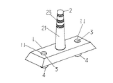
次に、本発明の実施の形態について図面を参照し、具体的に説明する。まず図1は本発明の実施の一形態を示す斜視図、図2はその主要部の断面図である。
【0014】
上記図面において、1は合成樹脂からなるブロック本体であり、用いられる合成樹脂の種類としては特に限定されるものではないが、屋外設置品であることから、適度な耐候性を有し、また車両の接触や乗り上げ等により破損しにくいように適度な粘弾性性状を有するものが好ましく、一般にはポリオレフイン系樹脂、塩化ビニル樹脂、ウレタン樹脂、ゴム、合成ゴム、塩化ビニルアクリル共重合樹脂、エチレン酢酸ビニル共重合樹脂等が好ましい。これらの合成樹脂は再生品でもよい。
【0015】
なおブロック本体1は前記の如く合成樹脂からなるので、コンクリート製より比重が小さいため、コンクリート製に比べて重量が1/3から1/2程度に軽量化できるが、薄肉にして内部を中空にすればさらに軽量化することができる。
【0016】
前記ブロック本体1は、道路の中央分離帯に沿って設置されるように一方向に長くなされ、且つ断面が台形状であって、後記のアンカーボルト3が挿入される取付孔11が穿設されると共に、中央部には後記の車線分離標2が支持される支持孔12が穿設されている。前記取付孔11はアンカーボルト3の頭部が隠蔽されるように段付きとなされ、そしてブロック本体1の両端部にそれぞれ1個づつ穿設されているが、1個でもよく、逆に3個以上であってもよい。また支持孔12は、ブロック本体1の表面より裏面に向かって拡開される円錐状の貫通孔となされている。
【0017】
2は柱状の車線分離標であり、一般には弾性を有する前記ブロック本体1と同様の合成樹脂からなり、中空円柱状の標示部21の下部に台座部22が形成され、その台座部22は、ブロック本体1に穿設された円錐状の支持孔12に対応して円錐状となされている。なお標示部21には車両のヘッドライトにより照射される光を再帰反射する反射テープ23等が適宜貼着される。
【0018】
3はブロック本体1の取付孔11に挿入されるアンカーボルトであり、4は路面Gに埋設されるアンカーナット4である。そして前記アンカーボルト3をブロック本体1の取付孔11に挿入すると共にブロック本体1の裏面側よりブロック本体1の支持孔12に車線分離標2を挿入し、次いで前記アンカーボルト3を路面Gに埋設されたアンカーナット4に螺着させれば、ブロック本体1が路面Gに取付けられると共に車線分離標2の台座部22がブロック本体1の支持孔12内面と路面Gとの間に挟着され、車線分離標2がブロック本体1に立設支持される。
【0019】
次に上記構成による中央分離帯用ブロックの設置方法を説明する。まず新規に設置する場合は、あらかじめブロック本体1の取付孔11にアンカーボルト3を挿入し、ブロック本体1の裏面側より、このアンカーボルト3にアンカーナット4を螺着させることにより、ブロック本体1の裏面にアンカーナット4を取付けておく。
【0020】
次にブロック本体1に取付けられた前記アンカーナット4の位置に合うように路面Gに埋設孔Hを開け、接着剤Sを充填する。そしてブロック本体1の裏面側よりブロック本体1の支持孔12に車線分離標2をその頭部より挿入し、ブロック本体1の支持孔12内面と車線分離標2の台座部22外面とを当接させた状態で、ブロック本体1に取付けられた前記アンカーナット4を埋設孔Hに挿入し、接着剤Sを固化させてアンカーナット4を路面Gに埋設させればよい。
【0021】
次に取り外す場合は、ブロック本体1のアンカーボルト3を緩めて取り外すことにより、ブロック本体1はアンカーナット4から取り外すことができ、またブロック本体1を取り外すと、車線分離標2はブロック本体1と路面Gとの間に挟着されているだけなので、車線分離標2も取り外すことができる。
【0022】
そして再び設置する場合は、既にアンカーナット4が路面Gに埋設されているので、アンカーボルト3をブロック本体1の取付孔11に挿入すると共にブロック本体1の裏面側よりブロック本体1の支持孔12に車線分離標2を挿入し、次いで前記アンカーボルト3を路面Gに埋設されたアンカーナット4に螺着させれば、ブロック本体1が路面Gに取付けられると共に車線分離標2の台座部22がブロック本体1の支持孔12内面と路面Gとの間に挟着され、車線分離標2がブロック本体1に立設支持される。
【0023】
なお上記形態では、アンカーボルト3をアンカーナット4に螺着させるだけで、容易に車線分離標2をブロック本体に立設支持させることができるが、図3は、ブロック本体1の支持孔12内面に雌ねじ13を形成し、一方の車線分離標2の下部には雄ねじ24を垂設し、この雄ねじ24を支持孔12内面の雌ねじ13に螺着させることにより、車線分離標2がブロック本体1に立設支持されるようになされているものを示している。かようになされていれば、ブロック本体1を取り外さずに、車線分離標2のみを取り外すことができる。
【0024】
次に図4は車線分離標を取付けるようにはなされていない中央分離帯用ブロックの一形態を示す斜視図、図5はその主要部の断面図である。この形態でのブロ ック本体1は、上記図1〜3に示されたブロック本体1とは車線分離標2を支持する支持孔12が穿設されていない点において相異するだけで、他はほぼ同様であり、道路の中央分離帯に沿って設置されるように一方向に長くなされた合成樹脂からなるブロック本体1に、アンカーボルト3が挿入される取付孔11が穿設され、この取付孔11に挿入させたアンカーボルト3を路面Gに埋設されたアンカーナット4に螺着させることにより、ブロック本体1が路面Gに取付けられるようになされている。そしてこのアンカーボルト3を脱着するだけで容易に路面Gに設置したり、取り外すことができるものである。
【0025】
【発明の効果】
請求項1に記載された本発明によれば、ブロック本体にアンカーボルトが挿入される取付孔が穿設され、この取付孔に挿入させたアンカーボルトを路面に埋設されたアンカーナットに螺着させることにより、ブロック本体が路面に取付けられるので、アンカーボルトを脱着するだけで容易に路面に設置したり、取り外すことができる。
【0026】
またブロック本体に柱状の車線分離標が支持される支持孔が穿設され、この支持孔に車線分離標の下部を挿入させて車線分離標がブロック本体に立設支持されるようになされているので、車線分離標を取り付ける孔を路面に別個に開ける等の別作業の必要がなく、ブロック本体の設置と同時に車線分離標も設置することができ、施工が容易且つ短時間となる。
【0027】
さらにブロック本体は合成樹脂から形成されているので、軽量であり、運搬や施工時に作業員に負担をかけず、また脆くないために運搬や施工時に落下させたり、施工後の車両の接触等によっても損傷しにくく、施工が容易となる。
【0028】
【図面の簡単な説明】
【図1】本発明の実施の一形態を示す斜視図である。
【図2】図1の主要部の断面図である。
【図3】中央分離帯用ブロックの一形態を示す断面図である。
【図4】車線分離標を取付けるようにはなされていない中央分離帯用ブロックの一形態を示す斜視図である。
【図5】図2の主要部の断面図である。
【符号の説明】
1 ブロック本体
11 取付孔
12 支持孔
13 雌ねじ
2 車線分離標
21 標示部
22 台座部
23 反射テープ
24 雄ねじ
3 アンカーボルト
4 アンカーナット
G 路面
H 埋設孔
S 接着剤[0001]
TECHNICAL FIELD OF THE INVENTION
The present invention relates to a method for installing a block for a median strip installed along a median strip on a road.
[0002]
[Prior art]
For example, in a provisional two-lane section of a toll road, etc., a more cautious driving is given to the driver to prevent the running vehicle from protruding from the center line and entering the oncoming lane, and to give the driver a sense of oppression visually. A median block is installed along the median of the road, or a median block and a columnar lane marker are installed along the median of the road in order to encourage the driver.
[0003]
And in order to install the median strip block and the lane marker as described above, conventionally, a hole for attaching the median block and a hole for attaching the lane marker are separately opened in advance on the road surface, After the hole is filled with the adhesive, the anchor portions formed at the lower ends of the median strip block and the lane marker are respectively embedded and fixed.
[0004]
[Problems to be solved by the invention]
As described above, conventionally, to install the median strip block and the lane separator, the installation of the median block and the installation of the lane marker were separate operations, so that time and labor were required for construction. I needed it. Also, once the median block or lane separator is installed on the road surface, it is buried and fixed on the road surface with adhesive, so if it is damaged by the vehicle, it can not be easily removed and replaced, Long-term construction with large lane regulations was required.
[0005]
In addition, the above-mentioned conventional median block is generally made of concrete, so it is heavy and puts a great burden on workers during transportation and construction, and because of its brittleness, it is dropped during transportation and construction, or It is easy to be damaged by the contact of the vehicle after the construction, etc. In any case, the construction requires time and labor.
[0006]
SUMMARY OF THE INVENTION The present invention has been made to solve the above-mentioned problems, and an object of the present invention is to provide a method of installing a block for a median strip which is easy to construct, remove and replace.
[0007]
[Means for Solving the Problems]
In order to achieve the above object, the present invention has the following configuration. That is, the method of installing a block for a median strip according to the present invention is a method of installing a block for a median strip consisting of a synthetic resin block body elongated in one direction so as to be installed along the median strip of a road. In the block body, a mounting hole for inserting an anchor bolt and a support hole for supporting a columnar lane marker are formed, and the support hole is expanded from the front surface of the block body toward the back surface. A cone-shaped pedestal portion is formed below the lane separation mark corresponding to the cone-shaped support hole, and an anchor bolt is inserted into a mounting hole of the block body in advance, and Anchor nut is screwed onto this anchor bolt from the back side, so that the anchor nut is attached to the back surface of the block body, and attached to the block body on the road surface A hole is buried so as to match the position of the anchor nut, filled with an adhesive, and a lane separator is inserted into the support hole of the block main body from the back side of the block main body from the back side of the block main body. In a state where the inner surface of the support hole and the outer surface of the pedestal portion of the lane marking are brought into contact with each other, the anchor nut attached to the block body is inserted into the burial hole, the adhesive is solidified, and the anchor nut is buried on the road surface. It is characterized by the following.
[0008]
According to the above invention, the block main body is provided with a mounting hole into which the anchor bolt is inserted, and the anchor bolt inserted into the mounting hole is screwed to the anchor nut embedded in the road surface, so that the block main body is mounted on the road surface. Because it can be installed on the road surface, it can be easily installed and removed on the road surface only by attaching and detaching the anchor bolt.
[0009]
A support hole for supporting a columnar lane marker is formed in the block body, and the lower part of the lane marker is inserted into the support hole so that the lane marker is supported upright on the block body. Therefore, there is no need to perform a separate operation such as separately opening a hole for attaching the lane marker on the road surface, and the lane marker can be installed simultaneously with the installation of the block main body, and the construction is easy and short.
[0010]
Furthermore, since the block body is made of synthetic resin, it is lightweight, does not place a burden on workers during transportation and construction, and because it is not brittle, it can be dropped during transportation or construction, or it may be contacted by vehicles after construction, etc. Is also less likely to be damaged, making construction easier.
[0011]
[0012]
[0013]
BEST MODE FOR CARRYING OUT THE INVENTION
Next, embodiments of the present invention will be specifically described with reference to the drawings. First, FIG. 1 is a perspective view showing an embodiment of the present invention, and FIG. 2 is a sectional view of a main part thereof.
[0014]
In the above drawings, reference numeral 1 denotes a block main body made of a synthetic resin, and the type of the synthetic resin used is not particularly limited. It is preferable that it has an appropriate viscoelastic property so that it is not easily damaged by contact with or climbing on, and generally, polyolefin resin, vinyl chloride resin, urethane resin, rubber, synthetic rubber, vinyl chloride acrylic copolymer resin, ethylene vinyl acetate Copolymer resins and the like are preferred. These synthetic resins may be recycled products.
[0015]
Since the block body 1 is made of a synthetic resin as described above, the specific gravity is smaller than that of concrete, so that the weight can be reduced to about 1/3 to 1/2 as compared with that of concrete. This can further reduce the weight.
[0016]
The block body 1 is elongated in one direction so as to be installed along the median strip of the road, has a trapezoidal cross section, and has a mounting hole 11 into which an
[0017]
Numeral 2 denotes a columnar lane separation marker, which is generally made of the same synthetic resin as the block main body 1 having elasticity, and has a
[0018]
[0019]
Next, a method of installing the block for the median strip having the above configuration will be described. First, when a new installation is performed, the
[0020]
Next, an embedding hole H is opened in the road surface G so as to match the position of the
[0021]
Next, when the block body 1 is to be removed, the block body 1 can be removed from the
[0022]
When re-installing, since the
[0023]
In the above embodiment, the
[0024]
Next, FIG. 4 is a perspective view showing an embodiment of a block for a median strip where a lane marker is not attached , and FIG. 5 is a cross-sectional view of a main part thereof. The block body 1 in this embodiment is different from the block body 1 shown in FIGS. 1 to 3 only in that a
[0025]
【The invention's effect】
According to the first aspect of the present invention, a mounting hole into which the anchor bolt is inserted is formed in the block body, and the anchor bolt inserted into the mounting hole is screwed to the anchor nut embedded in the road surface. Thus, since the block body is mounted on the road surface, it can be easily installed or removed on the road surface only by attaching and detaching the anchor bolt.
[0026]
A support hole for supporting a columnar lane marker is formed in the block body, and the lower part of the lane marker is inserted into the support hole so that the lane marker is supported upright on the block body. Therefore, there is no need to perform a separate operation such as separately opening a hole for attaching the lane marker on the road surface, and the lane marker can be installed simultaneously with the installation of the block main body, and the construction is easy and short.
[0027]
Furthermore, since the block body is made of synthetic resin, it is lightweight, does not place a burden on workers during transportation and construction, and because it is not brittle, it can be dropped during transportation or construction, or it may be contacted by vehicles after construction, etc. Is also less likely to be damaged, making construction easier.
[0028]
[Brief description of the drawings]
FIG. 1 is a perspective view showing an embodiment of the present invention.
FIG. 2 is a sectional view of a main part of FIG.
FIG. 3 is a cross-sectional view showing one embodiment of a block for a median strip.
FIG. 4 is a perspective view showing an embodiment of a median strip block to which a lane marker is not attached.
FIG. 5 is a sectional view of a main part of FIG. 2;
[Explanation of symbols]
1 Block Body 11
Claims (1)
Priority Applications (1)
| Application Number | Priority Date | Filing Date | Title |
|---|---|---|---|
| JP27960096A JP3569397B2 (en) | 1996-10-22 | 1996-10-22 | How to install median block |
Applications Claiming Priority (1)
| Application Number | Priority Date | Filing Date | Title |
|---|---|---|---|
| JP27960096A JP3569397B2 (en) | 1996-10-22 | 1996-10-22 | How to install median block |
Publications (2)
| Publication Number | Publication Date |
|---|---|
| JPH10121427A JPH10121427A (en) | 1998-05-12 |
| JP3569397B2 true JP3569397B2 (en) | 2004-09-22 |
Family
ID=17613254
Family Applications (1)
| Application Number | Title | Priority Date | Filing Date |
|---|---|---|---|
| JP27960096A Expired - Fee Related JP3569397B2 (en) | 1996-10-22 | 1996-10-22 | How to install median block |
Country Status (1)
| Country | Link |
|---|---|
| JP (1) | JP3569397B2 (en) |
Families Citing this family (8)
| Publication number | Priority date | Publication date | Assignee | Title |
|---|---|---|---|---|
| KR100510855B1 (en) | 2004-03-15 | 2005-08-30 | 주식회사 우전그린 | Prefabricated road median strip |
| JP4547310B2 (en) * | 2005-07-15 | 2010-09-22 | Jfe建材株式会社 | Guard fence joint structure and fixed structure |
| JP4820890B2 (en) * | 2009-06-18 | 2011-11-24 | 日本車輌製造株式会社 | Guard fence fixing structure |
| KR101111029B1 (en) | 2009-12-02 | 2012-03-13 | 김해정 | The Disassembly and Assembly type Median strip |
| JP2015117569A (en) * | 2013-12-19 | 2015-06-25 | 株式会社大晃工業 | Road traffic sign body and synchronously flashing system |
| CN106609502B (en) * | 2016-12-21 | 2019-06-18 | 浙江瑞堂塑料科技股份有限公司 | Plastic car stopping device with stone-like effect |
| JP6929727B2 (en) * | 2017-07-21 | 2021-09-01 | Nok株式会社 | Multi-stage resin mount block and lane division fence |
| CN110857550B (en) * | 2018-08-24 | 2021-05-25 | 中铁一局集团天津建设工程有限公司 | Urban road traffic safety protection device and construction method thereof |
-
1996
- 1996-10-22 JP JP27960096A patent/JP3569397B2/en not_active Expired - Fee Related
Also Published As
| Publication number | Publication date |
|---|---|
| JPH10121427A (en) | 1998-05-12 |
Similar Documents
| Publication | Publication Date | Title |
|---|---|---|
| US9245465B1 (en) | School bus stop safety breakaway arm extension | |
| US5769563A (en) | Highway warning device | |
| JP3569397B2 (en) | How to install median block | |
| WO2005113897A1 (en) | A road line safety pillar | |
| JP2003301427A (en) | Road signpost | |
| JPS6027126Y2 (en) | road studs | |
| US20020079034A1 (en) | Handy device for retrieving a vehicle stuck in a snow bank | |
| JP2003301426A (en) | Road signpost | |
| JP3253548B2 (en) | Road sign pole | |
| JPH078424U (en) | Car stop | |
| KR200434710Y1 (en) | Lane Regulation | |
| JP3594783B2 (en) | Road tack | |
| KR200345530Y1 (en) | road line delineator | |
| JP3914376B2 (en) | Road fence | |
| KR100412952B1 (en) | Road Stud | |
| JP4188849B2 (en) | Road sign pillar | |
| KR200395998Y1 (en) | The road a telltale | |
| JP2593488Y2 (en) | Block for simple separator | |
| KR100708440B1 (en) | Road Sign Bottle Construction Method | |
| JPH077375Y2 (en) | Road division marking tool | |
| JP2843516B2 (en) | Block-shaped road sign and its mounting method | |
| KR200297991Y1 (en) | Center-line separated lane control bar with integrated center line and reflective indicator | |
| KR102289466B1 (en) | Tubular Markers | |
| JPH08120631A (en) | Road separator | |
| KR200274729Y1 (en) | Movement a fence for a road |
Legal Events
| Date | Code | Title | Description |
|---|---|---|---|
| TRDD | Decision of grant or rejection written | ||
| A01 | Written decision to grant a patent or to grant a registration (utility model) |
Free format text: JAPANESE INTERMEDIATE CODE: A01 Effective date: 20040525 |
|
| A61 | First payment of annual fees (during grant procedure) |
Free format text: JAPANESE INTERMEDIATE CODE: A61 Effective date: 20040618 |
|
| R150 | Certificate of patent or registration of utility model |
Free format text: JAPANESE INTERMEDIATE CODE: R150 |
|
| FPAY | Renewal fee payment (event date is renewal date of database) |
Free format text: PAYMENT UNTIL: 20090625 Year of fee payment: 5 |
|
| FPAY | Renewal fee payment (event date is renewal date of database) |
Free format text: PAYMENT UNTIL: 20100625 Year of fee payment: 6 |
|
| FPAY | Renewal fee payment (event date is renewal date of database) |
Free format text: PAYMENT UNTIL: 20100625 Year of fee payment: 6 |
|
| FPAY | Renewal fee payment (event date is renewal date of database) |
Free format text: PAYMENT UNTIL: 20110625 Year of fee payment: 7 |
|
| FPAY | Renewal fee payment (event date is renewal date of database) |
Free format text: PAYMENT UNTIL: 20110625 Year of fee payment: 7 |
|
| FPAY | Renewal fee payment (event date is renewal date of database) |
Free format text: PAYMENT UNTIL: 20120625 Year of fee payment: 8 |
|
| FPAY | Renewal fee payment (event date is renewal date of database) |
Free format text: PAYMENT UNTIL: 20120625 Year of fee payment: 8 |
|
| FPAY | Renewal fee payment (event date is renewal date of database) |
Free format text: PAYMENT UNTIL: 20130625 Year of fee payment: 9 |
|
| FPAY | Renewal fee payment (event date is renewal date of database) |
Free format text: PAYMENT UNTIL: 20140625 Year of fee payment: 10 |
|
| LAPS | Cancellation because of no payment of annual fees |