JP3552853B2 - Room pressure control system - Google Patents
Room pressure control system Download PDFInfo
- Publication number
- JP3552853B2 JP3552853B2 JP23750996A JP23750996A JP3552853B2 JP 3552853 B2 JP3552853 B2 JP 3552853B2 JP 23750996 A JP23750996 A JP 23750996A JP 23750996 A JP23750996 A JP 23750996A JP 3552853 B2 JP3552853 B2 JP 3552853B2
- Authority
- JP
- Japan
- Prior art keywords
- target
- room
- pressure
- door
- chamber
- Prior art date
- Legal status (The legal status is an assumption and is not a legal conclusion. Google has not performed a legal analysis and makes no representation as to the accuracy of the status listed.)
- Expired - Fee Related
Links
Images


Description
【0001】
【発明の属する技術分野】
本発明は、クリーンルーム施設などで用いる室圧制御システムに関し、詳しくは、各対象室の検出室圧に基づき、各対象室に対する給気風路又は排気風路に介装の室圧調整用ダンパを開度調整して、各対象室の室圧を各々の目標室圧に調整する室圧制御手段を備える室圧制御システムに関する。
【0002】
【従来の技術】
従来、この種の室圧制御システムでは、対象室の用途変更の際などの初期設定として目標室圧を設定変更する、あるいは、給排気運転の開始時に室圧を漸次的に立ち上げるために目標室圧を漸次変更するといったこと以外に、各対象室の目標室圧を変更することはなく、定常の給排気運転中では、各対象室の目標室圧を固定した状態で、室圧制御手段による室圧制御を各々の対象室に対し実施していた。
【0003】
【発明が解決しようとする課題】
しかし、従来システムでは、目標室圧が互いに異なる対象室どうしの間に扉がある場合、この扉が開かれたときに、室圧制御状態にあるこれら対象室の室圧が、連通による均圧化で変化して目標室圧から外れ、また、その後、扉が閉じられたときに、一時的ではあるが、室圧が先の扉開き時の変化方向とは逆方向へ大きく変化して目標室圧から大きく外れる現象がある。
【0004】
そして、これら室圧変化のうち、扉の閉じ時の一時的な室圧変化は、扉開き時の室圧変化に比べ極端に大きく、この為、クリーンルームの清浄度維持を目的とする室圧制御の場合では、その清浄度維持の確実性が大きく低下するなど、種々の目的で実施する室圧制御において、その所期目的の達成の確実性が、扉閉じ時の極端な室圧変化のために大きく低下する問題があった。
【0005】
なお、この扉閉じ時における極端な室圧変化は、扉が開かれた後の室圧制御に原因するものであり、扉開き時の均圧化による室圧変化に対し、室圧制御手段が、連通状態となった両対象室の室圧を各々の目標室圧に復帰させる方向に各対象室に対する給気風路または排気風路の室圧調整用ダンパを開度調整するが、扉が開き状態にある間は、扉の開きによる両室の連通のため一方の対象室から他方の対象室へ侵入する漏れ的な風量が増大するばかりで、室圧が目標室圧に復帰することはなく、この為、室圧調整用ダンパは開度調整限界、ないしは、それに近い状態まで開度調整されてしまい、対象室における給気量と排気量の関係が、扉が開かれる以前のものとは全く異なったものとなる。そして、このように給排気量の関係が大きく狂った状態において、扉が閉じられる為に、上記の如き極端な室圧変化が生じる。
【0006】
また、この扉閉じ時における極端な室圧変化は、一方の対象室の室容積及び換気回数が他方の対象室に比べ十分に大きい場合には、扉開き時の均圧化による室圧変化が、その他方側の対象室の方でより大きく生じることから、扉閉じ時における極端な室圧変化も他方側の対象室の方で顕著に生じ、また、両対象室の室容積及び換気回数が同等である場合には、扉開き時の均圧化による室圧変化が、両対象室において同等(変化の向きは逆向き)に生じることから、扉閉じ時における極端な室圧変化も両対象室で同等(やはり変化の向きは逆向き)に生じる。
【0007】
以上の実情に対し、本発明の主たる課題は、扉の開閉に応じた室圧制御形態の合理的な切り換えにより、扉が開き状態にある間の室圧制御にかかわらず、扉閉じ時における室圧の極端な変化を効果的に抑止できるようにする点にある。
【0008】
【課題を解決するための手段】
〔請求項1記載の発明〕
請求項1記載の発明では、扉が開かれたとき、この扉の開きで連通状態となる二つの対象室の目標室圧のうちの一方、又は、両方を変更して、これら二つの対象室の目標室圧を一致させることにより、扉開き時の均圧化でこれら対象室の室圧が本来の目標室圧から外れることに対し、実質的に、これら連通状態となった対象室を一つの目標室圧(すなわち、上記の一致させた目標室圧)を有する一つの室圧制御対象室として扱かう形態で、これら対象室の各々に対する室圧調整用ダンパを、室圧制御手段により検出室圧に基づき開度調整するようにし、これにより、扉の開き後、これら二つの対象室の室圧をともに、上記の一致させた目標室圧に調整する。
【0009】
つまり、このことにより、先述の従来システムで生じていたダンパ調整上の問題、すなわち、扉の開きで両室が連通状態となって、これら対象室の室圧を互いに異なる各々の目標室圧に調整することがもはや不可能であるにもかかわらず、扉の開き後も互いに異なる各室の目標室圧を目指して室圧調整用ダンパが無意味に開度調整されるために、室圧調整用ダンパが開度調整限界や、それに近い状態に至ってしまうといったことを防止する。
【0010】
一方、扉が開き状態にある間は、両対象室を実質的に一室として扱う上記の室圧制御により、両対象室の室圧を一致の目標室圧に保ち、その後、扉が閉じられたとき、先の扉開き時に変更した目標室圧を元の値に復帰させることにより、再び、これら対象室を互いに異なる目標室圧を有する個別の室圧制御対象室として扱う形態で、これら対象室の各々に対する室圧調整用ダンパを、室圧制御手段により各室の検出室圧に基づき開度調整するようにし、これにより、これら対象室の室圧を各々の本来の目標室圧に調整する状態に戻る。
【0011】
すなわち、請求項1記載の発明によれば、扉の開き後、室圧調整用ダンパが無意味な開度調整で開度調整限界やそれに近い状態に至ってしまうことを防止できることにより、これに原因する扉閉じ時の極端な室圧変化を効果的に抑止できるようになり、これにより、クリーンルームの清浄度維持を目的とする室圧制御の場合では、その清浄度維持の確実性を向上し得るなど、種々の目的で実施する室圧制御において、その所期目的の達成を一層確実なものにし得る。
【0012】
なお、扉閉じ時における極端な室圧変化を抑止する別法としては、扉が開かれたとき、室圧制御手段による室圧調整用ダンパの開度調整を停止して、扉が開き状態にある間は、室圧調整用ダンパの開度を扉開き時点の開度に固定してしまい、そして、扉が閉じられたときに、室圧制御手段による室圧調整用ダンパの開度調整を再開するようにし、これにより、扉の開き後、室圧調整用ダンパが無意味に開度調整されて開度調整限界やそれに近い状態に至ってしまうことを防止するといった手法も考えられる。
【0013】
しかし、この別法では、扉が開き状態にある間、室圧調整用ダンパの開度が固定で対象室に対する室圧調整機能が皆無となるため、この間において、対象室で給気風路からの給気や排気風路への排気とは別の局所排気や局所給気が始動されるなど、給排気量関係についての何らかの変動要因があると、その影響で対象室の室圧が変動してしまう問題が残るが、請求項1記載の発明によれば、扉が開き状態にある間も、両対象室の室圧を上記一致の目標室圧に調整する室圧制御を実施するから、扉が開き状態にある間に、上記局所排気や局所給気が始動されるなど、給排気量関係について何らかの変動要因が生じたとしても、室圧制御機能により両対象室の室圧を上記一致の目標室圧に調整・維持することができ、この点、対象室の室圧を極力安定的に保つことにおいて、上記の別法に比べ一層優れた室圧制御システムとなる。
【0014】
〔請求項2記載の発明〕
請求項2記載の発明では、扉が開かれたとき、目標室圧の変更により、二つの対象室の目標室圧を一致させるにあたり、扉の開きで連通状態となる二つの対象室のうち、特定の一方の対象室の目標室圧は固定した状態で、他方の対象室の目標室圧のみを変更して、これら二つの対象室の目標室圧を、特定対象室である一方の対象室の目標室圧において一致させる。
【0015】
そして、この変更形態を採ることにより、扉が開き状態にある間も、一致の目標室圧を目指す室圧制御により、特定対象室である一方の対象室の室圧は、両室の連通にかかわらず、その本来の目標室圧に維持されるようにし、また、その後、扉の閉じに伴い、先の扉開き時に変更した他方の対象室の目標室圧を元の値に復帰させて元の室圧制御状態に戻る際も、特定対象室である一方の対象室については、室圧変化を殆ど伴うこと無く、その室圧を本来の目標室圧に保ったままの状態で元の室圧制御状態に戻れるようにする。
【0016】
つまり、請求項2記載の発明によれば、二つの対象室において、それらの室圧を各々の本来の目標室圧に維持することの必要性・重要性に差がある場合に、その必要性・重要性の高い方の対象室を上記の特定対象室として上記の変更形態を採ることにより、その必要性・重要性の高い方の対象室の室圧を、扉が開き状態にある間を通じて、また、その後の扉閉じの際も、その本来の目標室圧に安定的に維持しておくことができ、この点、扉の開きで連通状態となる二つの対象室のうち、清浄度の厳密維持などの理由で、特に一方の対象室の室圧をその本来の目標室圧に厳密に維持することが要求される場合などに有効な室圧制御システムとなる。
【0017】
〔請求項3記載の発明〕
請求項3記載の発明では、扉が開かれたとき、目標室圧の変更により、二つの対象室の目標室圧を一致させるにあたり、扉の開きで連通状態となる二つの対象室の目標室圧をともに、これら目標室圧どうしの間の設定中間値に変更して、これら二つの対象室の目標室圧を、その設定中間値で一致させる。
【0018】
そして、この変更形態を採ることにより、二つの対象室のうち、一方の対象室の目標室圧は固定した状態で、他方の対象室の目標室圧のみを変更して、両対象室の目標室圧を一致させる形態などに比べ、二つの対象室の双方について、扉が閉じ状態にあるときの室圧と、扉が開き状態にあるときの室圧との差を可及的に小さくできるようにする。
【0019】
つまり、請求項3記載の発明によれば、二つの対象室の双方について、扉が閉じ状態にあるときの室圧と、扉が開き状態にあるときの室圧との差を可及的に小さくできることにより、二つの対象室の室圧をともに、各々の本来の目標室圧に極力近い状態に保つことが要求される場合に有効な室圧制御システムとなる。
【0020】
〔請求項4記載の発明〕
請求項4記載の発明では、扉が開かれたとき、この扉の開きで連通状態となる二つの対象室の目標室圧をともに、これら目標室圧どうしの間の設定中間値に変更して、これら二つの対象室の目標室圧を、その設定中間値で一致させるにあたり、これら二つの対象室の扉開き時の室圧変化傾向度の比(すなわち、扉開き時に各室の室圧が均圧化の方向でどの程度変化するかの比)で、これら二つの目標室圧どうしの間を内分する内分点に相当の中間値を、その設定中間値とする。
【0021】
そして、この変更形態を採ることにより、扉の開きに伴い各対象室の室圧が均圧化の方向で変化することそのものが、一致の目標室圧である上記設定中間値への室圧調整となるようにして、扉の開きに対し、両室の室圧を設定中間値に調整するのに要する室圧調整用ダンパの開度調整量(換言すれば、給気量や排気量の変更量)が少ない状態で、速やかに両室の室圧を設定中間値に調整できるようにし、また、このことにより、その後の扉の閉じに伴い元の室圧制御状態に戻ることについても、室圧調整用ダンパの開度調整量の少ない状態で、速やかに両室の室圧を各々の本来の目標室圧に復帰できるようにする。
【0022】
つまり、請求項4記載の発明によれば、上記の如く、扉開き時及び扉の閉じ時の夫々について、室圧調整用ダンパの開度調整量の少ない状態で、両室の室圧を一致の目標室圧である設定中間値へ、また、各々の本来の目標室圧へ速やかに調整できることにより、対象室の室圧を極力安定的に保つことにおいて一層優れた室圧制御システムとなる。
【0023】
〔請求項5記載の発明〕
請求項5記載の発明では、扉が開かれたとき、この扉の開きで連通状態となる二つの対象室のうち、一方の対象室に対する室圧調整用ダンパを、その一方の対象室の検出室圧に基づき開度調整する独立調整状態(すなわち、その一方の対象室の目標室圧を目指して開度調整する状態)から、他方の対象室に対する室圧調整用ダンパの検出室圧に基づく開度調整(すなわち、その他方の対象室の目標室圧を目指すダンパ開度調整)に追従させて開度変化させる従動調整状態へ切り換える。
【0024】
つまり、この従動調整状態への切り換えを行うことにより、扉開き時の均圧化で両対象室の室圧が各々の本来の目標室圧から外れることに対し、実質的に、これら連通状態となった対象室を一つの目標室圧(具体的には上記他方の対象室の目標室圧)を有する一つの室圧制御対象室として扱かう形態で、上記他方の対象室に対する室圧調整用ダンパを検出室圧に基づき開度調整するとともに、これに追従させて、上記一方の対象室に対する室圧調整用ダンパを開度変化させるようにし、これにより、扉の開き後、これら二つの対象室の室圧をともに、上記他方の対象室の目標室圧に調整する。
【0025】
そして、このことにより、先述の従来システムで生じていたダンパ調整上の問題、すなわち、扉の開きで両室が連通状態となって、これら対象室の室圧を互いに異なる各々の目標室圧に調整することがもはや不可能であるにもかかわらず、扉の開き後も互いに異なる各室の目標室圧を目指して室圧調整用ダンパが無意味に開度調整されるために、室圧調整用ダンパが開度調整限界や、それに近い状態に至ってしまうといったことを防止する。
【0026】
一方、扉が開き状態にある間は、上記の如く一方の対象室に対する室圧調整用ダンパを従動調整状態に切り換えた室圧制御により、両対象室の室圧をともに他方の対象室の目標室圧に保ち、その後、扉が閉じられたとき、先の扉開き時に従動調整状態に切り換えた室圧調整用ダンパを独立調整状態へ復帰させることにより、再び、これら対象室を互いに異なる目標室圧を有する個別の室圧制御対象室として扱う形態で、これら対象室の各々に対する室圧調整用ダンパを、室圧制御手段により各室の検出室圧に基づき開度調整するようにし、これにより、これら対象室の室圧を各々の本来の目標室圧に調整する状態に戻る。
【0027】
つまり、請求項5記載の発明によれば、前述の請求項1記載の発明と同様、扉の開き後、室圧調整用ダンパが無意味な開度調整で開度調整限界やそれに近い状態に至ってしまうことを防止できることにより、これに原因する扉閉じ時の極端な室圧変化を効果的に抑止できるようになり、種々の目的で実施する室圧制御において、その所期目的の達成を一層確実なものにし得る。
【0028】
また、先述の別法に対しても、請求項1記載の発明と同様、扉が開き状態にある間も、両対象室の室圧ともに上記他方の対象室の目標室圧に調整する室圧制御を実施するから、扉が開き状態にある間に、対象室で局所排気や局所給気が始動されるなど、給排気量関係について何らかの変動要因が生じたとしても、室圧制御機能により両対象室の室圧を上記他方の対象室の目標室圧に調整・維持することができ、この点で、対象室の室圧を極力安定的に保つことにおいて、先述の別法に比べ一層優れた室圧制御システムとなる。
【0029】
【発明の実施の形態】
〔第1実施形態〕
図1において、1a〜1cは室圧制御対象の第1〜第3の対象室、Fsは主給気風路2を介して各対象室1a〜1cへ空調用空気SAを供給する給気ファン、Feは主排気風路3を介して各対象室1a〜1cから室内空気RAを排気する排気ファンであり、主給気風路2から各対象室1a〜1cに接続した分岐の給気風路4には夫々、各対象室1a〜1cへの給気量を各々の設定量に維持する定風量装置5、及び、給気用のフィルタ6を介装してある。
【0030】
また、主排気風路3から各対象室1a〜1cに接続した分岐の排気風路7には夫々、排気用のフィルタ8、及び、開度調整により各対象室1a〜1cの室圧pa〜pcを調整する室圧調整用ダンパVa〜Vcを介装してある。
【0031】
9a〜9cは、制御盤10から指定された各対象室1a〜1cの目標室圧ppa〜ppcと、室圧センサ11により検出される各対象室1a〜1cの室圧pa〜pc(具体的には大気圧などの適当な基準圧poに対する差圧)との偏差Δpa〜Δpcに応じ、室圧調整用ダンパVa〜Vcを開度調整して、各対象室1a〜1cの室圧pa〜pcを各々の目標室圧ppa〜ppc(例えば、ppa=30〔Pa〕,ppb=20〔Pa〕,ppc=0〔Pa〕)に調整する室圧制御手段としてのダンパ制御器である。
【0032】
なお、Lは、目標室圧ppa〜ppcの指定やダンパVa〜Vcの全閉・全開指令など、制御盤10からの種々の指令を各ダンパ制御器9a〜9cに送るとともに、各対象室1a〜1cの検出室圧pa〜pcや室圧調整用ダンパVa〜Vcの開度状態など、各ダンパ制御器9a〜9cからの情報を制御盤10に送る通信ラインである。
【0033】
第1の対象室1aと第2の対象室1bとの間の第1扉12、及び、第2の対象室1bと第3の対象室1cとの間の第2扉13には、夫々、これら扉12,13の開閉を検出して、その開閉の検出結果を制御盤10に送る開閉検出手段としての扉開閉検出器14a,14bを装備してあり、これに対し、制御盤10には、第1扉12や第2扉13が一旦開かれた後、再び閉じられたときの極端な室圧変化を防止する室圧保全手段として、扉開閉検出器14a,14bによる各扉12,13の開閉検出に基づき、扉開閉時に、対応対象室の目標室圧ppa〜ppcを自動的に変更する目標室圧自動変更部15を装備してある。
【0034】
そして、この目標室圧自動変更部15は、次の(イ)及び(ロ)の如く目標室圧の自動変更を実行する構成としてある。
【0035】
(イ)第1の対象室1aと第2の対象室1bについては、それらの室用途上、室圧pa,pbを各々の目標室圧ppa,ppbに維持することの必要性・重要性が第2対象室1bよりも第1対象室1aの方が高いことから、第1扉12の開きに対し、第1対象室1aを主対象室とし、かつ、第2対象室1bを副対象室として扱う。
【0036】
そして、この主副関係の下で、第1扉12が開かれたとき(図2参照)、主対象室である第1対象室1aの目標室圧ppa(=30Pa)は固定した状態で、副対象室である第2対象室1bの目標室圧ppb(=20Pa)を第1対象室1aの目標室圧ppaと等しい値に変更(ppb=20Pa→30Pa)し、これら第1対象室1aの目標室圧ppaと第2対象室1bの目標室圧ppbとを一致させる。
【0037】
また、その後、第1扉12が閉じられたとき(同図2参照)、先の第1扉12の開き時に変更した副対象室である第2対象室1bの目標室圧ppbを元の値に復帰(ppb=30Pa→20Pa)させる。
【0038】
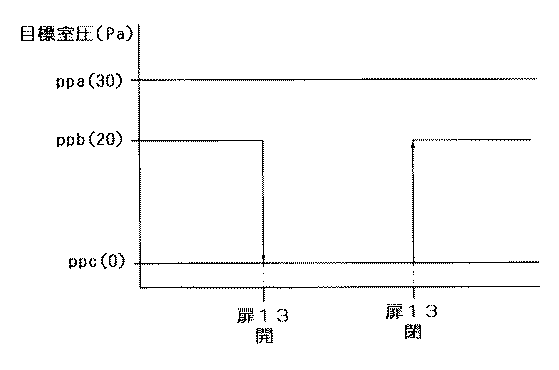
(ロ)第2の対象室1bと第3の対象室1cについては、それらの室用途上、室圧pb,pcを各々の目標室圧ppb,ppcに維持することの必要性・重要性が第2対象室1bよりも第3対象室1cの方が高いことから、第2扉13の開きに対し、第3対象室1cを主対象室とし、かつ、第2対象室1bを副対象室として扱う。
【0039】
そして、この主副関係の下で、第2扉13が開かれたとき(図3参照)、主対象室である第3対象室1cの目標室圧ppc(=0Pa)は固定した状態で、副対象室である第2対象室1bの目標室圧ppb(=20Pa)を第3対象室1cの目標室圧ppcと等しい値に変更(ppb=20Pa→0Pa)し、これら第2対象室1bの目標室圧ppbと第3対象室1cの目標室圧ppcとを一致させる。
【0040】
また、その後、第2扉13が閉じられたとき(同図3参照)、先の第2扉13の開き時に変更した副対象室である第2対象室1bの目標室圧ppbを元の値に復帰(ppb=0Pa→20Pa)させる。
【0041】
つまり、上記(イ),(ロ)の如く扉12,13の開き時に目標室圧の変更を実施して、扉12,13の開きで連通状態となる二つの対象室の目標室圧を一致させることにより、扉12,13が開き状態にある間に互いに異なる目標室圧を目指す開度調整のために室圧調整用ダンパVa,Vb,Vcが開度調整限界やそれに近い状態にまで無意味に調整されてしまうといったことを防止し、これにより、この無意味な開度調整に原因する扉閉じ時の極端な室圧変化を防止するようにしてある。
【0042】
〔第2実施形態〕
この第2実施形態では、上述の第1実施形態と同様の給排気構成において、 室圧保全手段としての目標室圧自動変更部15は、前記の(イ),(ロ)の如く目標室圧の自動変更を行うに代え、各対象室1a〜1cの換気条件が次記の通りであることに対し、次の(ハ),(ニ)の如く目標室圧の自動変更を行う構成とする。
【0043】
(ハ)第1の対象室1aと第2の対象室1bについては、第1扉12が開かれた時の両室の室圧変化傾向度の比Δpa:ΔPbが、近似的には両室の室容積と換気回数との積の逆比Db×nb:Da×naで与えられることから、この逆比(すなわち、室圧変化傾向度の比)で両室の目標室圧ppa,ppbどうしの間を内分する内分点に相当の下記中間値ppmを、目標室圧変更における変更目標の設定中間値とする。
ppm=X/Y
ここで、X=Da×na×ppa+Db×nb×ppb
Y=Da×na+Db×nb
【0045】
そして、この設定の下で、第1扉12が開かれたとき(図4参照)、第1対象室1aと第2対象室1bの目標室圧ppa(=30Pa),ppb(=20Pa)をともに、上記の設定中間値ppm(=28.8Pa)に変更(ppa=30Pa→28.8Pa,ppb=20Pa→28.8Pa)して、これら第1対象室1aの目標室圧ppaと第2対象室1bの目標室圧ppbとを一致させる。
【0046】
また、その後、第1扉12が閉じられたとき(同図4参照)、先の第1扉12の開き時に変更した両対象室1a,1bの目標室圧ppa,ppbを元の値に復帰(ppa=28.8Pa→30Pa,ppb=28.8Pa→20Pa)させる。
【0047】
(ニ)第2の対象室1bと第3の対象室1cについては、第2扉13が開かれた時の両室の室圧変化傾向度の比Δpb:Δpcが、上述と同様、近似的に両室の室容積と換気回数との積の逆比Dc×nc:Db×nbで与えられることから、この逆比(室圧変化傾向度の比)で両室の目標室圧ppb,ppcどうしの間を内分する内分点に相当の下記中間値ppnを、目標室圧変更における変更目標の設定中間値とする。
ppn=X’/Y’
ここで、X’=Db×nb×ppb+Dc×nc×ppc
Y=Db×nb+Dc×nc
【0048】
そして、この設定の下で、第2扉13が開かれたとき(図5参照)、第2対象室1bと第3対象室1cの目標室圧ppb(=20Pa),ppc(=0Pa)をともに、上記の設定中間値ppn(=6.6Pa)に変更(ppb=20Pa→6.6Pa,ppc=0Pa→6.6Pa)して、これら第2対象室1bの目標室圧ppbと第3対象室1cの目標室圧ppcとを一致させる。
【0049】
また、その後、第2扉13が閉じられたとき(同図5参照)、先の第2扉13の開き時に変更した両対象室1b,1cの目標室圧ppb,ppcを元の値に復帰(ppb=6.6Pa→20Pa,ppc=6.6Pa→0Pa)させる。
【0050】
つまり、上記(ハ),(ニ)の如く扉12,13の開き時に目標室圧の変更を実施して、扉12,13の開きで連通状態となる二つの対象室の目標室圧を一致させることにより、前述の第1実施形態の場合と同様、扉12,13が開き状態にある間に互いに異なる目標室圧を目指す開度調整のために室圧調整用ダンパVa,Vb,Vcが開度調整限界やそれに近い状態にまで無意味に調整されてしまうといったことを防止し、これにより、この無意味な開度調整に原因する扉閉じ時の極端な室圧変化を防止する。
【0051】
〔第3実施形態〕
この第3実施形態では、第1扉12や第2扉13が一旦開かれた後、再び閉じられたときの極端な室圧変化を防止する室圧保全手段として、前述の第1及び第2実施形態で示した如き目標室圧自動変更部15を設けるに代え、図6に示す如く、第1対象室1aのダンパ制御器9aと第2対象室1bのダンパ制御器9bとに対して第1のダンパ調整状態切換器16aを装備し、また、第2対象室1bのダンパ制御器9bと第3対象室1cのダンパ制御器9cとに対して第2のダンパ調整状態切換器16bを装備してある。
【0052】
これらダンパ調整状態切換器16a,16bは、扉開閉検出器14a,14bによる各扉12,13の開閉検出に基づき、扉開閉時に、対応対象室のうちの一方の対象室の室圧調整用ダンパVa〜Vcに対する開度調整形態を切り換えるものであり、具体的には、第1のダンパ調整状態切換器16aは次の(ホ)の如く開度調整形態の切り換えを行い、また、第2のダンパ調整状態切換器16bは次の(ヘ)の如く開度調整形態の切り換えを行う構成としてある。
【0053】
(ホ)第1の対象室1aと第2の対象室1bについては、それらの室用途上、室圧pa,pbを各々の目標室圧ppa,ppbに維持することの必要性・重要性が第2対象室1bよりも第1対象室1aの方が高いことから、第1扉12の開きに対し、第1対象室1aを主対象室とし、かつ、第2対象室1bを副対象室として扱う。
【0054】
そして、この主副関係の下で、第1扉12が開かれたとき、主対象室である第1対象室1aの室圧調整用ダンパVaについては、第1対象室1aの検出室圧paに基づき第1対象室1aの目標室圧ppaを目指して開度調整する独立調整状態を維持したままで、副対象室である第2対象室1bの室圧調整用ダンパVbを、第2対象室1bの検出室圧pbに基づき第2対象室1bの目標室圧ppbを目指して開度調整するそれまでの独立調整状態から、主対象室である第1対象室1aの室圧調整用ダンパVaの開度調整に追従させて開度変化させる従動調整状態へ切り換える。
また、その後、第1扉12が閉じられたとき、先の第1扉12の開き時に従動調整状態へ切り換えた第2対象室1bの室圧調整用ダンパVbを、従動調整状態から、第2対象室1bの検出室圧pbに基づき第2対象室1bの目標室圧ppbを目指して開度調整する独立調整状態へ復帰させる。
(へ)第2の対象室1bと第3の対象室1cについては、それらの室用途上、室圧pb,pcを各々の目標室圧ppb,ppcに維持することの必要性・重要性が第2対象室1bよりも第3対象室1cの方が高いことから、第2扉13の開きに対し、第3対象室1cを主対象室とし、かつ、第2対象室1bを副対象室として扱う。
【0057】
そして、この主副関係の下で、第2扉13が開かれたとき、主対象室である第3対象室1cの室圧調整用ダンパVcについては、第3対象室1cの検出室圧pcに基づき第3対象室1cの目標室圧ppcを目指して開度調整する独立調整状態を維持したままで、副対象室である第2対象室1bの室圧調整用ダンパVbを、第2対象室1bの検出室圧pbに基づき第2対象室1bの目標室圧ppbを目指して開度調整するそれまでの独立調整状態から、主対象室である第3対象室1cの室圧調整用ダンパVcの開度調整に追従させて開度変化させる従動調整状態へ切り換える。
また、その後、第2扉13が閉じられたとき、先の第2扉13の開き時に従動調整状態へ切り換えた第2対象室1bの室圧調整用ダンパVbを、従動調整状態から、第2対象室1bの検出室圧pbに基づき第2対象室1bの目標室圧ppbを目指して開度調整する独立調整状態へ復帰させる。
つまり、上記(ホ),(ヘ)の如く扉12,13の開き時に、連通状態となる二つの対象室のうちの一方の室圧調整用ダンパVbを、他方の対象室の室圧調整用ダンパVa,Vbの開度調整に追従させて開度変化させる従動調整状態に切り換えることにより、扉12,13が開き状態にある間に互いに異なる目標室圧を目指す開度調整のために室圧調整用ダンパVa,Vb,Vcが開度調整限界やそれに近い状態にまで無意味に調整されてしまうといったことを防止し、これにより、この無意味な開度調整に原因する扉閉じ時の極端な室圧変化を防止する。
【0060】
なお、上記の従動調整状態において、一方の室圧調整用ダンパVbを、他方の対象室の室圧調整用ダンパVa,Vcの開度調整に追従させて開度変化させる具体的追従方式ついては、従動調整状態に切り換えた室圧調整用ダンパVbを、その切り換え時点の開度から、独立調整状態維持側の室圧調整用ダンパVa,Vcの開度変更に伴い、その変更率と同率に開度変化させる方式、あるいはまた、従動調整状態に切り換えた室圧調整用ダンパVbを、独立調整状態維持側の室圧調整用ダンパVa,Vcと同開度を維持するように開度変化させる方式などを一例として挙げることができる。
【0061】
〔別の実施形態〕
次に発明の別の実施形態を列記する。
扉が開かれたとき、この扉の開きで連通状態となる二つの対象室の目標室圧のうちの一方のみを変更して、これら対象室の目標室圧を一致させる方式を採る場合、前述の第1実施形態では、室圧を本来の目標室圧に維持することの必要性・重要性が高い方の対象室を目標室圧固定側とする例を示したが、両室に上記必要性・重要性の差がない場合などでは、扉開閉時における室圧調整用ダンパの開度調整量を極力少なくすることを目的として、扉開き時の室圧変化傾向度が小さい方の対象室を目標室圧固定側とするようにしてもよい。
【0062】
扉が開かれたとき、この扉の開きで連通状態となる二つの対象室の目標室圧の両方を、これら目標室圧どうしの間の設定中間値に変更して、これら対象室の目標室圧を一致させる方式を採る場合、前述の第2実施形態では、扉開き時の両室の室圧変化傾向度の比で、両室の目標室圧どうしの間を内分する内分点に相当の中間値を上記の設定中間値としたが、これに代え、この内分点相当の中間値以外の中間値を上記の設定中間値とするようにしてもよい。
【0063】
また、扉が開かれたとき、この扉の開きで連通状態となる二つの対象室の目標室圧の両方を変更して、これら対象室の目標室圧を一致させるにあたり、場合によっては、両対象室の目標室圧どうしの間から外れた値で、両対象室の目標室圧を一致させるようにしてもよい。
【0064】
前述の第1及び第2実施形態では、扉が開かれたときに目標室圧の変更を行う室圧保全手段としての目標室圧自動変更部15を、制御盤10に組み込み装備する形式を示したが、この目標室圧自動変更部15は、制御盤10とは別の単体器で構成してもよい。
【0065】
また、前述の第3実施形態では、扉が開かれたときに従動調整状態への切り換えを行う室圧保全手段としてのダンパ調整状態切換器16a,16bを、制御盤10とは別の単体器で構成する形式を示したが、これらダンパ調整状態切換器16a,16bは制御盤10に組み込み装備する形式としてもよい。
【0066】
扉が開かれたとき、この扉の開きで連通状態となる二つの対象室のうち、一方の対象室の室圧調整用ダンパを、独立調整状態から他方の対象室の室圧調整用ダンパの開度調整に追従させて開度変化させる従動調整状態に切り換える方式を採る場合、前述の第3実施形態では、室圧を本来の目標室圧に維持することの必要性・重要性が低い方の対象室の室圧調整用ダンパを、従動調整状態に切り換える側のダンパとする例を示したが、両室に上記必要性・重要性の差がない場合などでは、扉開閉時における室圧調整用ダンパの開度調整量を極力少なくすることを目的として、扉開き時の室圧変化傾向度が大きい方の対象室の室圧調整用ダンパを、従動調整状態に切り換える側のダンパとするようにしてもよい。
【0067】
前述の各実施形態では、各対象室の排気風路に室圧調整用ダンパを介装する形式を示したが、本発明は、室圧調整用ダンパを各対象室の給気風路に介装する形式や、室圧調整用ダンパを各対象室の給気風路と排気風路の双方に介装する形式においても適用できる。
【0068】
扉の開閉を検出する開閉検出手段は、機械式のリミットスイッチや、光学利用により扉開閉を検出する方式、あるいは、磁気利用により開閉を検出する方式など、種々の方式のものを採用できる。
【0069】
対象室はクリーンルームに限らず、どのような用途のものであってもよい。
【0070】
なお、前記の第1扉12と第2扉13とがともに開き状態となることがある場合には、先に開かれた扉に対応する2室につき本発明を適用して、これら2室を実質的に1室として扱う前述の如き室圧制御を実施し、その上で、後の扉の開きに対して、この実質的1室扱いの2室と他の1室とについて、さらに本発明を適用する形態で、結果的に、両扉12,13の開きに対し、これら扉12,13の開きで連通状態となる三つの対象室の目標室圧のうちの2つ、又は、全部を変更して、これら三つの対象室の目標室圧を一致させる、又は、両扉12,13の開きに対し、これら扉12,13の開きで連通状態となる三つの対象室のうち、二つの対象室に対する室圧調整用ダンパを、独立調整状態から、他の三つ目の対象室に対する室圧調整用ダンパに追従させて開度変化させる従動調整状態へ切り換えようにすればよい。
【図面の簡単な説明】
【図1】第1及び第2実施形態を示すシステム構成図
【図2】第1実施形態における目標室圧の変更形態を示す図
【図3】第1実施形態における目標室圧の変更形態を示す図
【図4】第2実施形態における目標室圧の変更形態を示す図
【図5】第2実施形態における目標室圧の変更形態を示す図
【図6】第3実施形態を示すシステム構成図
【符号の説明】
1a,1b 対象室
pa,pb 室圧
4 給気風路
7 排気風路
Va,Vb 室圧調整用ダンパ
ppa,ppb 目標室圧
9a,9b 室圧制御手段
12 扉
14a 開閉検出手段
15,16a 室圧保全手段
ppm 設定中間値[0001]
TECHNICAL FIELD OF THE INVENTION
The present invention relates to a room pressure control system used in a clean room facility or the like, and more specifically, opens a room pressure adjustment damper interposed in a supply air passage or an exhaust air passage for each target room based on a detected room pressure of each target room. The present invention relates to a room pressure control system including room pressure control means for adjusting a room pressure of each target room to each target room pressure by adjusting a degree.
[0002]
[Prior art]
Conventionally, in this type of room pressure control system, the target room pressure is changed as an initial setting when the purpose of the target room is changed, or the target pressure is gradually increased at the start of the supply / exhaust operation. Except for gradually changing the room pressure, the target room pressure of each target room is not changed.During a steady supply / exhaust operation, the target room pressure of each target room is fixed and the room pressure control means is not changed. Is controlled for each target room.
[0003]
[Problems to be solved by the invention]
However, in the conventional system, when there is a door between target chambers having different target chamber pressures, when the door is opened, the room pressures of the target rooms in the room pressure control state are equalized by the communication. When the door is closed, the room pressure changes temporarily but in a direction opposite to the direction in which the door was opened, but temporarily, when the door is closed. There is a phenomenon that greatly deviates from the room pressure.
[0004]
Of these room pressure changes, the temporary room pressure change when the door is closed is extremely large compared to the room pressure change when the door is opened. Therefore, the room pressure control for maintaining cleanliness of the clean room is performed. In the case of, in the room pressure control performed for various purposes, such as the reliability of maintaining the cleanliness greatly reduced, the reliability of achieving the intended purpose depends on the extreme room pressure change when the door is closed. There was a problem that it greatly reduced.
[0005]
The extreme change in room pressure when the door is closed is due to the control of the room pressure after the door is opened. The opening degree of the chamber pressure adjusting damper of the supply air path or the exhaust air path for each target chamber is adjusted in the direction of returning the chamber pressures of the two target chambers in the communicating state to the respective target chamber pressures, but the door opens. While in the state, the leaking air volume entering from one target chamber to the other target chamber only increases due to communication between the two chambers by opening the door, and the chamber pressure does not return to the target chamber pressure. Therefore, the damper for adjusting the room pressure is adjusted to the opening adjustment limit or to a state close to the opening adjustment limit, and the relationship between the air supply amount and the exhaust amount in the target room is different from that before the door was opened. It will be completely different. Then, in such a state where the relationship between the supply and exhaust air amounts is largely out of order, since the door is closed, the above-described extreme change in the chamber pressure occurs.
[0006]
In addition, when the room volume and the number of ventilations in one of the target rooms are sufficiently larger than those in the other target room, the room pressure change due to the equalization when the door is opened is an extreme room pressure change when the door is closed. , Since it occurs more in the target room on the other side, an extreme change in the chamber pressure when the door is closed also significantly occurs in the target room on the other side. If they are the same, the room pressure change due to pressure equalization when the door is opened occurs equally (the direction of change is opposite) in both target rooms, so the extreme room pressure change when the door is closed is also applied to both subjects. It occurs equally in the room (again, the direction of change is opposite).
[0007]
In view of the above situation, the main problem of the present invention is that the room pressure control mode according to the opening and closing of the door is rationally switched, so that the room pressure at the time of closing the door regardless of the room pressure control while the door is open. The point is that extreme changes in pressure can be effectively suppressed.
[0008]
[Means for Solving the Problems]
[Invention of claim 1]
According to the first aspect of the present invention, when the door is opened, one or both of the target chamber pressures of the two target chambers that are in communication with each other when the door is opened are changed to change the two target chambers. By making the target chamber pressures of the target chambers equal to each other, the chamber pressures of these target chambers deviate from the original target chamber pressures by equalizing when the doors are opened. The room pressure control means detects room pressure adjusting dampers for each of the target chambers in such a manner that the chambers are treated as one room pressure control chamber having two target chamber pressures (that is, the above-mentioned matched target chamber pressures). The opening is adjusted based on the room pressure, so that after the door is opened, the room pressures of the two target rooms are both adjusted to the above-mentioned target room pressure that has been matched.
[0009]
In other words, this causes a problem in damper adjustment that has occurred in the above-described conventional system, that is, the two chambers communicate with each other when the door is opened, and the chamber pressures of the target chambers are set to different target chamber pressures from each other. Even though it is no longer possible to adjust the room pressure, the room pressure adjustment damper is meaninglessly adjusted to the target room pressure of each different room even after the door is opened. It is possible to prevent the damper for use from reaching the opening adjustment limit or a state close thereto.
[0010]
On the other hand, while the door is in the open state, the room pressure control that treats both target rooms as substantially one room maintains the room pressures of both target rooms at the same target room pressure, and then the door is closed. Then, by returning the target chamber pressure changed when the door was opened earlier to the original value, these target chambers are treated again as individual chamber pressure control target chambers having different target chamber pressures from each other. The opening degree of the chamber pressure adjusting damper for each of the chambers is adjusted based on the detected chamber pressure of each chamber by the chamber pressure control means, thereby adjusting the chamber pressures of the target chambers to their original target chamber pressures. Return to the state to do.
[0011]
That is, according to the first aspect of the present invention, it is possible to prevent the chamber pressure adjusting damper from reaching an opening adjustment limit or a state close to the opening adjustment limit by meaningless opening adjustment after the door is opened. It is possible to effectively suppress an extreme change in the room pressure when the door is closed, thereby improving the certainty of maintaining the cleanliness in the case of the room pressure control for the purpose of maintaining the cleanliness of the clean room. For example, in room pressure control performed for various purposes, the intended purpose can be more reliably achieved.
[0012]
As another method for suppressing an extreme change in the room pressure when the door is closed, when the door is opened, the opening adjustment of the room pressure adjusting damper by the room pressure control means is stopped, and the door is opened. During a certain time, the opening of the room pressure adjusting damper is fixed to the opening at the time of opening the door, and when the door is closed, the opening of the room pressure adjusting damper is adjusted by the room pressure controlling means. It is also possible to consider a method of restarting, so as to prevent the chamber pressure adjusting damper from being unnecessarily adjusted in opening after the door is opened to reach the opening adjustment limit or a state close thereto.
[0013]
However, in this alternative method, while the door is open, the opening degree of the room pressure adjusting damper is fixed and there is no function of adjusting the room pressure with respect to the target room. If there are any fluctuation factors related to the air supply / exhaust volume, such as the start of local exhaust or local air supply that is different from the air supply or exhaust air flow, the room pressure of the target room will fluctuate due to the effect. According to the first aspect of the present invention, while the door is in the open state, the chamber pressure of both the target chambers is adjusted to the same target chamber pressure while the door is open. Even if the local exhaust or the local air supply is started while the valve is in the open state, even if some variation factor occurs in the supply / exhaust amount relationship, the room pressure control function adjusts the room pressures of both the target rooms to the above-mentioned coincidence. It can be adjusted and maintained at the target room pressure. In keeping the Joteki becomes more excellent room pressure controlling system compared to alternative methods described above.
[0014]
[Invention of claim 2]
In the invention according to
[0015]
By adopting this modification, even when the door is in the open state, the room pressure of one target room, which is the specific target room, is set to the communication between the two rooms by the room pressure control aiming at the coincident target room pressure. Regardless, the target chamber pressure is maintained at the original target chamber pressure, and then, when the door is closed, the target chamber pressure of the other target chamber, which was changed when the previous door was opened, is returned to the original value. When returning to the room pressure control state, the target room, which is the specific target room, hardly changes in room pressure, and the room pressure is maintained at the original target room pressure while maintaining the original room pressure. So that it can return to the pressure control state.
[0016]
In other words, according to the second aspect of the present invention, when there is a difference between the necessity and importance of maintaining the chamber pressures at the original target chamber pressures in the two target chambers, the necessity is maintained. -By adopting the above modified form with the target room with higher importance as the above-mentioned specific target room, the necessity-The room pressure of the target room with higher importance will be increased while the door is open. In addition, when the door is closed thereafter, the original target chamber pressure can be stably maintained, and in this regard, of the two target chambers that are in communication with each other when the door is opened, the cleanliness level is low. This is an effective chamber pressure control system especially when it is required to maintain the chamber pressure of one of the target chambers strictly at its original target chamber pressure for reasons such as strict maintenance.
[0017]
[Invention of claim 3]
According to the third aspect of the present invention, when the door is opened, the target chamber pressures of the two target chambers are brought into communication with each other by opening the door when the target chamber pressures of the two target chambers are matched by changing the target chamber pressure. Both the pressures are changed to a set intermediate value between these target chamber pressures, and the target chamber pressures of these two target chambers are made to match with the set intermediate value.
[0018]
By adopting this modification, the target room pressure of one of the two target rooms is fixed, and only the target room pressure of the other target room is changed. Compared to a configuration in which the chamber pressures are matched, the difference between the chamber pressure when the door is closed and the chamber pressure when the door is open can be reduced as much as possible for both of the two target rooms. To do.
[0019]
That is, according to the third aspect of the present invention, the difference between the room pressure when the door is in the closed state and the room pressure when the door is in the open state for both of the two target rooms is minimized. By being able to reduce, the room pressure control system is effective when it is required to keep the room pressures of the two target chambers as close as possible to the respective original target room pressures.
[0020]
[Invention of claim 4]
According to the fourth aspect of the present invention, when the door is opened, the target chamber pressures of the two target chambers that are brought into communication with each other by opening the door are both changed to an intermediate value between the target chamber pressures. In order to match the target room pressures of these two target rooms at the set intermediate value, the ratio of the tendency of the room pressure change tendency when the doors of the two target rooms are opened (that is, the room pressure of each room when the doors are opened) An intermediate value corresponding to an internal dividing point that internally divides between these two target chamber pressures is set as the set intermediate value.
[0021]
By adopting this modified form, the fact that the chamber pressure of each target chamber changes in the direction of equalization with the opening of the door itself is equivalent to the adjustment of the chamber pressure to the above-mentioned set intermediate value, which is the coincident target chamber pressure. The opening adjustment amount of the chamber pressure adjusting damper required to adjust the chamber pressure in both chambers to the set intermediate value in response to the opening of the door (in other words, the change in the air supply amount or exhaust amount) Volume) is small, so that the room pressure in both chambers can be quickly adjusted to the set intermediate value. This also makes it possible to return to the original room pressure control state with subsequent closing of the door. In a state where the opening adjustment amount of the pressure adjusting damper is small, the chamber pressures of both chambers can be promptly returned to their original target chamber pressures.
[0022]
That is, according to the fourth aspect of the present invention, as described above, when the door is opened and when the door is closed, the chamber pressures of the two chambers are matched with each other with the opening adjustment amount of the chamber pressure adjusting damper being small. Can be quickly adjusted to the set intermediate value, which is the target chamber pressure, and to the respective original target chamber pressures, thereby providing a more excellent room pressure control system in keeping the chamber pressure of the target chamber as stable as possible.
[0023]
[Invention according to claim 5]
According to the fifth aspect of the present invention, when the door is opened, the chamber pressure adjusting damper for one of the two target chambers that are in communication with each other when the door is opened is detected by detecting the one of the target chambers. From the independent adjustment state in which the opening degree is adjusted based on the room pressure (that is, the state in which the opening degree is adjusted aiming at the target chamber pressure of one of the target chambers), based on the detected chamber pressure of the room pressure adjusting damper for the other target room. The state is switched to the driven adjustment state in which the opening degree is changed by following the opening degree adjustment (that is, the damper opening degree aiming at the target chamber pressure of the other target chamber).
[0024]
In other words, by performing the switching to the driven adjustment state, the chamber pressures of both the target chambers deviate from the respective original target chamber pressures by equalization when the door is opened. In the form in which the changed target room is treated as one room pressure control target room having one target room pressure (specifically, the target room pressure of the other target room), the room pressure for the other target room is adjusted. The opening degree of the damper is adjusted based on the detected chamber pressure, and the opening degree of the chamber pressure adjusting damper for the one of the target chambers is changed by following the opening degree. The room pressure of the room is adjusted to the target room pressure of the other target room.
[0025]
Then, due to this, the problem of damper adjustment that has occurred in the above-described conventional system, that is, the two chambers are in communication with each other when the door is opened, and the chamber pressures of these target chambers are set to different target chamber pressures from each other. Even though it is no longer possible to adjust the room pressure, the room pressure adjustment damper is meaninglessly adjusted to the target room pressure of each different room even after the door is opened. It is possible to prevent the damper for use from reaching the opening adjustment limit or a state close thereto.
[0026]
On the other hand, while the door is in the open state, the room pressure of both the target chambers is set to the target of the other target room by the room pressure control in which the room pressure adjusting damper for one of the target rooms is switched to the driven adjustment state as described above. By maintaining the room pressure, and thereafter, when the door is closed, the room pressure adjustment damper, which has been switched to the driven adjustment state when the door was opened earlier, is returned to the independent adjustment state. In the form of treating as individual chamber pressure control target chambers having pressure, the chamber pressure adjustment dampers for each of these target chambers are adjusted by the chamber pressure control means based on the detected chamber pressure of each chamber, whereby the opening degree is adjusted. Then, the state returns to the state in which the chamber pressures of the target chambers are adjusted to their original target chamber pressures.
[0027]
In other words, according to the fifth aspect of the present invention, similarly to the first aspect of the present invention, after the door is opened, the chamber pressure adjusting damper is brought into a state close to or near the opening adjustment limit by meaningless opening adjustment. As a result, it is possible to effectively suppress an extreme change in room pressure when the door is closed due to this, and further achieve the intended purpose in the room pressure control performed for various purposes. Can be assured.
[0028]
Also in the alternative method described above, as in the first aspect of the invention, while the door is in the open state, the chamber pressure of both the target chambers is adjusted to the target chamber pressure of the other target chamber. Since the control is performed, even if any change factors occur in the air supply / exhaust volume relationship, such as when local exhaust or local air supply is started in the target room while the door is open, the room pressure control function will The room pressure of the target room can be adjusted and maintained at the target room pressure of the other target room. In this respect, in maintaining the room pressure of the target room as stable as possible, it is more excellent than the aforementioned alternative method. Room pressure control system.
[0029]
BEST MODE FOR CARRYING OUT THE INVENTION
[First Embodiment]
In FIG. 1,
[0030]
The branch
[0031]
[0032]
L sends various commands from the
[0033]
The
[0034]
The target chamber pressure automatic changing
[0035]
(A) For the
[0036]
Then, under the main-sub relationship, when the
[0037]
After that, when the
[0038]
(B) Regarding the
[0039]
When the
[0040]
After that, when the
[0041]
That is, the target chamber pressure is changed when the
[0042]
[Second embodiment]
In the second embodiment, in the same supply / exhaust configuration as in the first embodiment described above, the target chamber pressure automatic changing
[0043]
(C) As for the
ppm = X / Y
Here, X = Da × na × ppa + Db × nb × ppb
Y = Da × na + Db × nb
[0045]
Under this setting, when the
[0046]
After that, when the
[0047]
(D) For the
ppn = X '/ Y'
Here, X ′ = Db × nb × ppb + Dc × nc × ppc
Y = Db × nb + Dc × nc
[0048]
Under this setting, when the
[0049]
After that, when the
[0050]
That is, the target chamber pressure is changed when the
[0051]
[Third embodiment]
In the third embodiment, the first and
[0052]
These damper
[0053]
(E) Regarding the
[0054]
Under the main-sub relationship, when the
After that, when the
(F) Regarding the
[0057]
Then, under the main-sub relationship, when the
After that, when the
That is, when the
[0060]
In addition, in the above-described driven adjustment state, a specific following method in which the opening degree of one chamber pressure adjusting damper Vb is changed by following the opening degree adjustment of the chamber pressure adjusting dampers Va and Vc of the other target chamber is described below. The room pressure adjusting damper Vb switched to the driven adjustment state is opened at the same rate as the opening degree of the chamber pressure adjusting dampers Va and Vc on the independent adjustment state maintaining side from the opening degree at the time of the switching. Or a method of changing the opening degree of the chamber pressure adjustment damper Vb switched to the driven adjustment state so as to maintain the same opening degree as the chamber pressure adjustment dampers Va and Vc on the independent adjustment state maintaining side. And the like can be cited as an example.
[0061]
[Another embodiment]
Next, another embodiment of the invention will be listed.
When the door is opened, when only one of the target chamber pressures of the two target chambers that are in communication with each other when the door is opened is changed to adopt a method of matching the target chamber pressures of these target chambers, In the first embodiment, an example is shown in which the target chamber having the higher necessity and importance of maintaining the chamber pressure at the original target chamber pressure is set to the target chamber pressure fixed side. In the case where there is no difference in the characteristics and importance, for the purpose of minimizing the opening adjustment amount of the room pressure adjustment damper when opening and closing the door, the target room with the smaller tendency of the room pressure change when the door is opened May be set to the target chamber pressure fixed side.
[0062]
When the door is opened, both of the target chamber pressures of the two target chambers that are brought into communication by opening the door are changed to an intermediate value between the target chamber pressures, and the target chambers of the target chambers are changed. In the case of adopting the method of matching the pressures, in the above-described second embodiment, the ratio of the tendency of the room pressure change between the two chambers when the door is opened is set to the internal dividing point that internally separates the target chamber pressures of the two chambers. Although the corresponding intermediate value is set as the above-described set intermediate value, an intermediate value other than the intermediate value corresponding to the subdivision point may be set as the above-described set intermediate value instead.
[0063]
In addition, when the door is opened, both target chamber pressures of the two target chambers that are in communication with each other when the door is opened are changed to match the target chamber pressures of these target chambers. The target chamber pressures of the two target chambers may be made to coincide with each other by a value deviating from between the target chamber pressures of the target chambers.
[0064]
In the first and second embodiments, the
[0065]
In the third embodiment described above, the damper adjustment state switches 16a and 16b as room pressure maintenance means for switching to the driven adjustment state when the door is opened are provided as a single unit separate from the
[0066]
When the door is opened, of the two target chambers that are in communication with each other when the door is opened, the chamber pressure adjustment damper of one of the target chambers is changed from the independent adjustment state to the chamber pressure adjustment damper of the other target chamber. In the case of adopting a method of switching to a driven adjustment state in which the opening is changed by following the opening adjustment, in the third embodiment, the necessity and importance of maintaining the chamber pressure at the original target chamber pressure is lower. In the above example, the room pressure adjustment damper of the target room is set to the damper that switches to the driven adjustment state. For the purpose of minimizing the opening adjustment amount of the adjustment damper as much as possible, the room pressure adjustment damper of the target room having the larger tendency of changing the room pressure when the door is opened is used as the damper for switching to the driven adjustment state. You may do so.
[0067]
In each of the above-described embodiments, the type in which the room pressure adjusting damper is interposed in the exhaust air passage of each target room is shown. However, the present invention provides that the room pressure adjusting damper is installed in the supply air passage of each target room. The present invention can also be applied to a type in which a damper for adjusting the room pressure is interposed in both the supply air path and the exhaust air path of each target room.
[0068]
As the opening / closing detecting means for detecting the opening / closing of the door, various types such as a mechanical limit switch, a system for detecting the opening / closing of the door by utilizing an optical system, or a system for detecting the opening / closing by utilizing a magnetic field can be adopted.
[0069]
The target room is not limited to a clean room, but may be of any use.
[0070]
In the case where the
[Brief description of the drawings]
FIG. 1 is a system configuration diagram showing first and second embodiments.
FIG. 2 is a diagram showing a change mode of a target chamber pressure in the first embodiment.
FIG. 3 is a diagram showing a change mode of a target chamber pressure in the first embodiment.
FIG. 4 is a diagram showing a change mode of a target chamber pressure in a second embodiment.
FIG. 5 is a diagram showing a change mode of a target chamber pressure in a second embodiment.
FIG. 6 is a system configuration diagram showing a third embodiment.
[Explanation of symbols]
1a, 1b Target room
pa, pb Room pressure
4 Supply air path
7 Exhaust air path
Va, Vb Room pressure adjustment damper
ppa, ppb Target chamber pressure
9a, 9b Room pressure control means
12 doors
14a Open / close detection means
15, 16a Room pressure maintenance means
ppm setting intermediate value
Claims (5)
前記対象室どうしの間の扉の開及び閉を検出する開閉検出手段と、
この開閉検出手段により前記扉の開が検出されたとき、この扉の開きで連通状態となる二つの前記対象室の目標室圧のうちの一方、又は、両方を変更して、これら二つの前記対象室の目標室圧を一致させ、
かつ、前記開閉検出手段により前記扉の閉が検出されたとき、先の扉開き時に変更した目標室圧を変更前の元の値に復帰させる室圧保全手段を設けた室圧制御システム。Based on the detected chamber pressure of each target room, the opening degree of the room pressure adjusting damper interposed in the supply air passage or exhaust air passage for each target room is adjusted so that the room pressure of each target room becomes the target room pressure. A room pressure control system comprising room pressure control means for adjusting,
Opening and closing detection means for detecting the opening and closing of the door between the target chambers,
When the opening of the door is detected by the open / close detection means, one or both of the target chamber pressures of the two target chambers that are in communication with each other by opening the door are changed, and the two Match the target room pressure of the target room,
Further, a room pressure control system provided with a room pressure maintenance means for returning the target room pressure changed when the door was opened earlier to the original value before the change when the opening / closing detection means detects the closing of the door.
前記対象室どうしの間の扉の開及び閉を検出する開閉検出手段と、
この開閉検出手段により前記扉の開が検出されたとき、この扉の開きで連通状態となる二つの前記対象室のうち、一方の対象室に対する前記室圧調整用ダンパを、その一方の対象室の検出室圧に基づき開度調整する独立調整状態から、他方の対象室に対する前記室圧調整用ダンパの検出室圧に基づく開度調整に追従させて開度変化させる従動調整状態へ切り換え、
かつ、前記開閉検出手段により前記の閉が検出されたとき、先の扉開き時に従動調整状態へ切り換えた前記室圧調整用ダンパを切り換え前の独立調整状態へ復帰させる室圧保全手段を設けた室圧制御システム。Based on the detected chamber pressure of each target room, the opening degree of the room pressure adjusting damper interposed in the supply air passage or exhaust air passage for each target room is adjusted so that the room pressure of each target room becomes the target room pressure. A room pressure control system comprising room pressure control means for adjusting,
Opening and closing detection means for detecting the opening and closing of the door between the target chambers,
When the opening of the door is detected by the opening / closing detection means, the chamber pressure adjusting damper for one of the two target chambers, which is in communication with the opening of the door, is connected to one of the target chambers. Switching from an independent adjustment state in which the opening degree is adjusted based on the detection chamber pressure to a driven adjustment state in which the opening degree is changed by following the opening degree adjustment based on the detection chamber pressure of the room pressure adjustment damper for the other target chamber,
Further, when the closing is detected by the opening / closing detecting means, a chamber pressure maintaining means for returning the chamber pressure adjusting damper, which has been switched to the driven adjustment state when the door was opened, to the independent adjustment state before switching, is provided. Room pressure control system.
Priority Applications (1)
| Application Number | Priority Date | Filing Date | Title |
|---|---|---|---|
| JP23750996A JP3552853B2 (en) | 1996-09-09 | 1996-09-09 | Room pressure control system |
Applications Claiming Priority (1)
| Application Number | Priority Date | Filing Date | Title |
|---|---|---|---|
| JP23750996A JP3552853B2 (en) | 1996-09-09 | 1996-09-09 | Room pressure control system |
Publications (2)
| Publication Number | Publication Date |
|---|---|
| JPH1083221A JPH1083221A (en) | 1998-03-31 |
| JP3552853B2 true JP3552853B2 (en) | 2004-08-11 |
Family
ID=17016383
Family Applications (1)
| Application Number | Title | Priority Date | Filing Date |
|---|---|---|---|
| JP23750996A Expired - Fee Related JP3552853B2 (en) | 1996-09-09 | 1996-09-09 | Room pressure control system |
Country Status (1)
| Country | Link |
|---|---|
| JP (1) | JP3552853B2 (en) |
Families Citing this family (14)
| Publication number | Priority date | Publication date | Assignee | Title |
|---|---|---|---|---|
| JP4608799B2 (en) * | 2001-04-05 | 2011-01-12 | 澁谷工業株式会社 | Indoor pressure control device |
| JP4904014B2 (en) * | 2005-04-11 | 2012-03-28 | ダイダン株式会社 | Air conditioning system |
| JP4630125B2 (en) * | 2005-05-13 | 2011-02-09 | ダイダン株式会社 | Air conditioning system |
| JP4714517B2 (en) * | 2005-07-12 | 2011-06-29 | ダイダン株式会社 | Air conditioning system |
| JP4755861B2 (en) * | 2005-07-14 | 2011-08-24 | ダイダン株式会社 | Air conditioning system |
| JP5014770B2 (en) * | 2006-12-20 | 2012-08-29 | ダイダン株式会社 | Room pressure control system |
| JP4924031B2 (en) * | 2006-12-28 | 2012-04-25 | マックス株式会社 | Ventilation system |
| JP5049599B2 (en) * | 2007-01-11 | 2012-10-17 | ダイダン株式会社 | Room pressure control method and apparatus |
| JP5049608B2 (en) * | 2007-02-07 | 2012-10-17 | ダイダン株式会社 | Room pressure control system using multi-stage CAV |
| JP5118425B2 (en) * | 2007-09-14 | 2013-01-16 | アズビル株式会社 | Room pressure control device and room pressure control method |
| JP5262336B2 (en) * | 2008-06-18 | 2013-08-14 | ダイキン工業株式会社 | Air conditioning system |
| JP4712853B2 (en) * | 2008-10-14 | 2011-06-29 | 高砂熱学工業株式会社 | Room pressure control system |
| JP5150741B2 (en) * | 2011-02-09 | 2013-02-27 | ダイダン株式会社 | Air conditioning system |
| JP5296903B2 (en) * | 2012-05-18 | 2013-09-25 | アズビル株式会社 | Room pressure control device and room pressure control method |
-
1996
- 1996-09-09 JP JP23750996A patent/JP3552853B2/en not_active Expired - Fee Related
Also Published As
| Publication number | Publication date |
|---|---|
| JPH1083221A (en) | 1998-03-31 |
Similar Documents
| Publication | Publication Date | Title |
|---|---|---|
| JP3552853B2 (en) | Room pressure control system | |
| US5829674A (en) | Zone system control | |
| JPH08254347A (en) | Global control system of distribution system for heating, ventilation and air conditioning | |
| CN114383297A (en) | Method and device for controlling air conditioner and multi-split air conditioner | |
| JP4188956B2 (en) | Room pressure control system for multiple rooms | |
| JPH0252775B2 (en) | ||
| JP2002181361A (en) | Control device for room pressure | |
| JP2006078086A (en) | Room pressure control system | |
| JP2010002080A (en) | Air conditioning system | |
| JP2003083578A (en) | Clean room | |
| JP3089130B2 (en) | Room pressure control device | |
| JP2008267615A (en) | Ventilation system | |
| JPH07158935A (en) | Fan coil unit | |
| JP5033106B2 (en) | Room pressure control system | |
| JP2898944B2 (en) | Air-conditioning system for controlling space pressure | |
| JP3044205B2 (en) | Room pressure control device | |
| JP3789622B2 (en) | Air conditioning system | |
| JPH0926803A (en) | Fuzzy adaptive controller | |
| JP3230783B2 (en) | Room pressure control device | |
| JP3623060B2 (en) | Room pressure control system | |
| JPH01256743A (en) | Room pressure regulating device for plurality of rooms | |
| JPH0692835B2 (en) | Room pressure control system | |
| JPH0842902A (en) | Vav control system | |
| JPH01306761A (en) | Variable air flow rate controller | |
| CN110608515B (en) | Air conditioning system and control method thereof |
Legal Events
| Date | Code | Title | Description |
|---|---|---|---|
| A977 | Report on retrieval |
Free format text: JAPANESE INTERMEDIATE CODE: A971007 Effective date: 20040205 |
|
| TRDD | Decision of grant or rejection written | ||
| A01 | Written decision to grant a patent or to grant a registration (utility model) |
Free format text: JAPANESE INTERMEDIATE CODE: A01 Effective date: 20040415 |
|
| A61 | First payment of annual fees (during grant procedure) |
Free format text: JAPANESE INTERMEDIATE CODE: A61 Effective date: 20040427 |
|
| R150 | Certificate of patent or registration of utility model |
Free format text: JAPANESE INTERMEDIATE CODE: R150 |
|
| R250 | Receipt of annual fees |
Free format text: JAPANESE INTERMEDIATE CODE: R250 |
|
| FPAY | Renewal fee payment (event date is renewal date of database) |
Free format text: PAYMENT UNTIL: 20090514 Year of fee payment: 5 |
|
| FPAY | Renewal fee payment (event date is renewal date of database) |
Free format text: PAYMENT UNTIL: 20100514 Year of fee payment: 6 |
|
| FPAY | Renewal fee payment (event date is renewal date of database) |
Free format text: PAYMENT UNTIL: 20110514 Year of fee payment: 7 |
|
| FPAY | Renewal fee payment (event date is renewal date of database) |
Free format text: PAYMENT UNTIL: 20120514 Year of fee payment: 8 |
|
| FPAY | Renewal fee payment (event date is renewal date of database) |
Free format text: PAYMENT UNTIL: 20130514 Year of fee payment: 9 |
|
| FPAY | Renewal fee payment (event date is renewal date of database) |
Free format text: PAYMENT UNTIL: 20140514 Year of fee payment: 10 |
|
| R250 | Receipt of annual fees |
Free format text: JAPANESE INTERMEDIATE CODE: R250 |
|
| R250 | Receipt of annual fees |
Free format text: JAPANESE INTERMEDIATE CODE: R250 |
|
| LAPS | Cancellation because of no payment of annual fees |