JP3552575B2 - Intake control device for internal combustion engine - Google Patents
Intake control device for internal combustion engine Download PDFInfo
- Publication number
- JP3552575B2 JP3552575B2 JP06488099A JP6488099A JP3552575B2 JP 3552575 B2 JP3552575 B2 JP 3552575B2 JP 06488099 A JP06488099 A JP 06488099A JP 6488099 A JP6488099 A JP 6488099A JP 3552575 B2 JP3552575 B2 JP 3552575B2
- Authority
- JP
- Japan
- Prior art keywords
- valve
- scavenging
- time
- engine
- opening
- Prior art date
- Legal status (The legal status is an assumption and is not a legal conclusion. Google has not performed a legal analysis and makes no representation as to the accuracy of the status listed.)
- Expired - Fee Related
Links
Images

Classifications
-
- Y—GENERAL TAGGING OF NEW TECHNOLOGICAL DEVELOPMENTS; GENERAL TAGGING OF CROSS-SECTIONAL TECHNOLOGIES SPANNING OVER SEVERAL SECTIONS OF THE IPC; TECHNICAL SUBJECTS COVERED BY FORMER USPC CROSS-REFERENCE ART COLLECTIONS [XRACs] AND DIGESTS
- Y02—TECHNOLOGIES OR APPLICATIONS FOR MITIGATION OR ADAPTATION AGAINST CLIMATE CHANGE
- Y02T—CLIMATE CHANGE MITIGATION TECHNOLOGIES RELATED TO TRANSPORTATION
- Y02T10/00—Road transport of goods or passengers
- Y02T10/10—Internal combustion engine [ICE] based vehicles
- Y02T10/40—Engine management systems
Description
【0001】
【発明の属する技術分野】
本発明は内燃機関の吸気制御装置に関し、特に、機関の始動時に電子制御スロットル弁の閉弁制御が行われると共に、始動困難時には燃焼室内の未燃焼燃料の掃気制御が行われる内燃機関の吸気制御装置に関する。
【0002】
【従来の技術】
近年、コンピュータの発達に伴い、内燃機関の回転数を電子的に最適に制御しようとする電子制御式の内燃機関が実用化されている。このような内燃機関の電子制御化としては、例えば、燃料噴射量制御、点火時期制御、吸排気弁の開弁時期の制御等が先行しており、これらに続いてスロットル弁の電子制御も実用段階に入っている。スロットル弁の開度を電子制御する内燃機関では、アクセルペダルの踏込量に関係なくスロットル弁の開度を設定することができる。
【0003】
このため、電子制御スロットル弁を使用して機関の始動時に吸気通路を閉じることにより、始動時の吸気量を減少させると共に、吸気管負圧を高めて燃料の気化促進を図ることが提案されている。これは、電子制御式の内燃機関では各燃焼室近傍の吸気通路内に燃料噴射弁が装着されているために、始動時に燃料が十分に微粒化しないことがあり、このときに始動性が悪化するのを防止するためである。
【0004】
一方、電子制御燃料噴射式の内燃機関において、機関の冷間始動時等に機関がなかなか始動せず、過大な燃料噴射によって始動不良を起こした場合に、クランキングは継続させたままで燃料噴射を停止し、燃焼室内の未燃焼燃料を掃気して始動性を向上させる技術がある。この掃気制御の技術は、例えば、特開平5−231213号公報や特開平5−321714号公報に開示されている。
【0005】
【発明が解決しようとする課題】
しかしながら、機関の始動時の燃料の気化促進のためにスロットル弁を始動時に閉弁制御する内燃機関に前述の掃気制御技術を適用しようとすると、スロットル弁が閉じられたままで掃気制御を行うことになり、掃気が十分に行えずに始動不良が解消しないという問題点があった。
【0006】
そこで、本発明は、電子制御開閉弁が吸気通路に設けられた多気筒内燃機関であって機関の始動時に電子制御開閉弁の閉弁制御を行い、かつ、機関の始動不良時には掃気制御を行うものにおいて、始動時の電子制御開閉弁の閉弁制御と始動不良時の掃気制御の両立を図ることができ、機関の始動性の向上、及びエミッション悪化の防止を実現することができる内燃機関の吸気制御装置を提供することを目的としている。
【0007】
【課題を解決するための手段】
前記目的を達成する本発明の第1の形態は、吸気通路に電子制御開閉弁を備え、内燃機関の始動時に開閉弁を全閉位置に制御する始動時の閉弁制御を行う内燃機関の吸気制御装置において、クランキング中の燃料噴射を停止して燃焼室内の未燃焼燃料の掃気を実行する掃気手段と、掃気が実行されている時には開閉弁の始動時の閉弁制御を停止する始動時の閉弁制御停止手段と、掃気が実行されている時の機関回転数を監視し、掃気実行中に機関回転数が基準値を越えて増大した時には、掃気手段と始動時の閉弁制御停止手段の動作を停止して開閉弁の始動時の閉弁制御を再開する始動時の閉弁制御再開手段とを設けたことを特徴としている。
【0008】
前記目的を達成する本発明の第2の形態は、吸気通路に電子制御開閉弁を備え、内燃機関の始動時に開閉弁を全閉位置に制御する始動時の閉弁制御を行う内燃機関の吸気制御装置において、クランキング中の燃料噴射時に、大気圧、大気圧補正係数、機関の補機の動作状態の運転状態パラメータを読み込み、読み込んだ運転状態パラメータに基づいて機関アイドル時のISC流量の学習値を補正して機関のISC流量を算出し、算出したISC流量を流すISC開度に開閉弁の開度を設定する開度設定手段と、クランキング時間を計数し、その計数値が所定値を越えた時に、クランキング中の燃料噴射を停止して、燃焼室内の未燃焼燃料の掃気を実行する掃気手段と、掃気が実行されている時には開閉弁の始動時の閉弁制御を停止して、開閉弁の開度をISC開度以上に開く始動時の閉弁制御停止手段と、掃気が実行されている時の機関回転数を監視し、掃気実行中に機関回転数が基準値を越えて増大した時には、掃気手段と始動時の閉弁制御停止手段の動作を停止して、開閉弁の始動時の閉弁制御を再開し、開閉弁の開度をISC開度に設定する始動時の閉弁制御再開手段とを設けたことを特徴としている。
【0009】
第1の形態において、更に、機関のクランキング時間を検出するクランキング時間検出手段を設け、このクランキング時間検出手段の計数値が所定値を越えた時に掃気手段が動作するようにすることができる。
第1又は第2の形態において、始動時の閉弁制御停止手段は、始動時の閉弁制御を中止する際に、開閉弁を全開状態にすることができる。
【0010】
本発明の第1の形態によれば、機関の始動時に電子制御開閉弁の閉弁制御を行う内燃機関であって、始動不良時に掃気制御を実行し、掃気制御実行中においても点火が継続している状態において、スロットル弁を開いた状態で機関が始動してしまった場合でも、機関回転数が基準値まで増大した時にスロットル弁の閉弁制御が再開されるので、機関回転数が暴走することなく機関を始動させることができる。
本発明の第2の形態によれば、機関の始動時に電子制御開閉弁の閉弁制御を行う内燃機関であって、始動不良時に掃気制御を実行し、掃気制御実行中においても点火が継続している状態において、スロットル弁を開いた状態で機関が始動してしまった場合でも、機関回転数が基準値まで増大した時に掃気が停止されると共に、開閉弁の開度がISC開度に設定されるので、機関回転数が暴走することなく機関を始動させることができる。
【0011】
【発明の実施の形態】
以下添付図面を用いて本発明の実施形態を具体的な実施例に基づいて詳細に説明する。
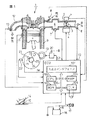
図1には本発明の一実施例の吸気制御装置を備えた電子制御燃料噴射式の多気筒内燃機関1が概略的に示されている。図1において、内燃機関1の吸気通路2には図示しないエアクリーナの下流側にスロットル弁3が設けられている。このスロットル弁3の軸の一端にはこのスロットル弁3を駆動するアクチュエータであるスロットルモータ4が設けられており、他端にはスロットル弁3の開度を検出するスロットル開度センサ5が設けられている。即ち、この実施例のスロットル弁3は、アクセルペダル14の開度をアクセル開度センサ15で検出し、その開度や機関に取り付けられた電子制御機器の各制御信号と合わせて後述するECU(エンジン・コントロール・ユニット)10で最適なスロットル開度を決定し、スロットルモータ4によって開閉駆動される電子制御スロットル(以後、単に電子スロットルと記す)に組み込まれたものである。電子スロットルでは、スロットル弁3の開度指令値がECU10から入力された時に、スロットルモータ4がこの指令値に応答してスロットル弁3を指令開度に追従させる。
【0012】
吸気通路2のスロットル弁3の上流側には大気圧センサ18があり、下流側にはサージタンク6がある。このサージタンク6内には吸気の圧力を検出する圧力センサ7が設けられている。更に、サージタンク6の下流側には、各気筒毎に燃料供給系から加圧燃料を吸気ポートへ供給するための燃料噴射弁8が設けられている。スロットル開度センサ5の出力と圧力センサ7の出力は、マイクロコンピュータを内蔵したECU10に入力される。
【0013】
また、内燃機関1のシリンダブロックの冷却水通路9には、冷却水の温度を検出するための水温センサ11が設けられている。水温センサ11は冷却水の温度に応じたアナログ電圧の電気信号を発生する。排気通路12には、排気ガス中の3つの有害成分HC,CO,NOxを同時に浄化する三元触媒コンバータ(図示せず)が設けられており、この触媒コンバータの上流側の排気通路12には、空燃比センサの一種であるO2 センサ13が設けられている。O2 センサ13は排気ガス中の酸素成分濃度に応じて電気信号を発生する。これら水温センサ11及びO2 センサ13の出力はECU10に入力される。
【0014】
更に、このECU10には、アクセル開度センサ15からのアクセルペダルの踏込量信号(アクセル開度信号)、バッテリ16に接続されたイグニッションスイッチ17からのキー位置信号(アクセサリ位置、オン位置、スタータ位置)、クランクシャフトの一端に取り付けられたクランクシャフトタイミングプーリと一体型のタイミングロータ24に近接した設けられたクランク位置センサ21からの上死点信号TDCや所定角度毎のクランク角信号CAや、油温センサ22からの潤滑油の温度が入力される。また、クランクシャフトの他端に設けられたリングギヤ23は機関1の始動時にスタータ19によって回転させられる。
【0015】
機関回転数Neは、所定クランク角信号CAの間隔(時間)を計測することにより得られる。タイミングロータ24には信号歯25が設けられており、上死点の検出用に2枚の欠歯部26を備えた34歯となっている。クランク位置センサ21は電磁ピックアップから構成することができ、10°毎のクランク回転信号を出力する。クランク位置センサ21は欠歯部26の箇所の信号を検出することにより、正確な上死点を検出することができる。また、内燃機関の燃料噴射が実行される気筒は、このクランク位置センサ21からの信号と、図示しないカム位置センサからの信号により判別することができる。
【0016】
従来の内燃機関では、一般に直流直巻モータから構成されるスタータ19はイグニッションスイッチ17がスタータ位置にされた時にオンするスタータスイッチを介してバッテリ16に接続されている。従って、イグニッションスイッチ17がオンされ、その後にイグニッションスイッチ17がスタータ位置にされた時にスタータ19が起動されて機関1が始動する。そして、機関1が稼働を開始すると、ECU10が通電されてプログラムが起動し、各センサからの出力を取り込み、スロットル弁3を開閉するスロットルモータ4や燃料噴射弁8、或いはその他のアクチュエータを制御する。ECU10には、各種センサからのアナログ信号をディジタル信号に変換するA/D変換器が含まれ、各種センサからの入力ディジタル信号や各アクチュエータを駆動する信号が出入りする入出力インタフェース101、演算処理を行うCPU102、ROM103やRAM104等のメモリや、クロック105等が設けられており、これらはバス106で相互に接続されている。ECU10の構成については公知であるので、これ以上の説明を省略する。
【0017】
一方、この実施例では、スタータ19が直接バッテリ16に接続されておらず、スタータ駆動回路20を介してバッテリ16に接続されている。そして、このスタータ駆動回路20は、ECU10からのスタータ信号STが入力されないとスタータ19をバッテリ16に接続しないようになっている。
この実施例では、機関1の始動時にスロットル弁3を一時的に閉弁して吸気通路2をほぼ閉塞し、スロットル弁3の下流側に負圧を発生させて機関の始動性を向上させている。一方、機関1が停止している時には、スロットル弁3は全閉位置にはなく、僅かにあいている。従って、機関1が停止している状態では、スロットル弁3の吸気通路2内は大気圧になっている。
【0018】
従って、機関1を始動させる時には、スロットルモータ4を駆動してスロットル弁3を全閉位置に制御する必要がある。なお、ここでいうスロットル弁3の全閉位置3は、スロットル弁3と吸気通路2とが衝突した状態ではなく、僅かに隙間が開いている位置のことであり、この実施例では、この隙間は最小限の空気流量が流れる程度の隙間である。このため、ECU10には、前述のようにイグニッションスイッチ17からのキー位置信号とスロットル開度センサ5からのスロットル開度信号が入力されている。
【0019】
ここで、以上のように構成された機関1の始動時に、ECU10が実行するスロットル弁3の駆動制御の手順、および燃料の噴射制御について、その実施例を図2から図5、及び図7のフローチャートを用いて説明する。
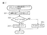
図2は電子制御スロットル弁3の閉制御を実行するフラグFTHVCの設定手順を示すフローチャートである。図2に示すルーチンは機関1の始動時にのみイニシャルルーチンにおいて所定時間毎、例えば、数ms毎に実行される。
【0020】
この制御では、まずステップ201において図1で説明した水温センサ11によって検出された機関水温THWを読み込む。続くステップ202では、この水温が所定温度A℃〜B℃の範囲にあるか否かを判定する。水温THWがこの範囲にない時にはステップ204に進み、スロットル弁閉制御実行フラグFTHVCを“0”にしてこのルーチンを終了する。一方、水温THWがこの範囲に入っている時にはステップ203に進み、スロットル弁閉制御実行フラグFTHVCを“1”にしてこのルーチンを終了する。このスロットル弁閉制御実行フラグFTHVCは“1”の時に、スロットル弁の閉弁制御が行われることを示す。
【0021】
なお、この実施例では、水温THWがごく低温のA℃未満と、ごく高温のB℃を越えた温度においてはスロットル弁閉制御実行フラグFTHVCを“0”にして、スロットル弁閉制御を実行しないようにしているが、これは現時点における機関の始動性の信頼性を高めるためであり、コストをかけて制御精度を高めるようにすれば、始動時のスロットル弁閉制御は、機関の水温条件に無関係に実行することも可能である。
【0022】
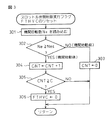
このようにして機関1の始動時に水温THWがA≦THW≦Bの範囲にある時に“1”に設定されるスロットル弁閉制御実行フラグFTHVCは、機関1が始動してから所定時間後にリセットされる。スロットル弁閉制御実行フラグFTHVCのリセット時間は、例えば、スロットル弁を閉弁した時のスロットル弁下流側の空気量が機関の始動後になくなる時間を考慮して設定することができる。この制御を図3に示すフローチャートを用いて説明する。図3に示すルーチンも機関1の始動時にのみイニシャルルーチンにおいて所定時間毎、例えば、数ms毎に実行される。
【0023】
この制御では、まず、ステップ301において機関回転数Neを読み込む。機関回転数Neは図1に示したクランク位置センサ21からのクランク位置信号から算出することができるものである。続くステップ302ではステップ301で読み込んだ機関回転数Neが設定回転数Nes以上か否か、例えば400rpm以上か否かを判定する。機関回転数Neが設定回転数Nes未満の時は、機関1が未だ始動していないと判定してステップ303に進み、始動後経過時間カウンタCNTの値をクリアしてこのルーチンを終了する。
【0024】
一方、ステップ302において、機関回転数Neが設定回転数Nes以上の場合は機関1が始動したと判定してステップ304に進み、始動後経過時間カウンタCNTの値を1だけインクリメントしてステップ305に進む。ステップ305では始動後経過時間カウンタCNTの値が所定時間を示す基準計数値Cに達したか否かを判定する。そして、始動後経過時間カウンタCNTの値が基準計数値Cに達していない時はこのままこのルーチンを終了し、始動後経過時間カウンタCNTの値が基準計数値Cに達した時はステップ306に進んでスロットル弁閉制御実行フラグFTHVCを“0”にしてこのルーチンを終了する。このようにして、機関1の始動時に“1”になっていたスロットル弁閉制御実行フラグFTHVCは、機関1が始動してから所定時間が経過すると“0”に設定される。
【0025】
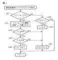
図4は図1のように構成された内燃機関1における掃気制御実行フラグFSCVの設定手順を示すフローチャートである。図4に示すルーチンも機関1の始動時にのみイニシャルルーチンにおいて所定時間毎、例えば、数ms毎に実行される。掃気制御は、イグニッションスイッチ17のオンによりスロットル弁3が全閉にされた後に、スタータ19によってクランキングされたが、なかなか始動しない場合に実行される。即ち、掃気制御は、機関1の冷間始動時等にクランキングを長時間に渡って続けても機関1がなかなか始動しない場合に、燃料噴射弁8から噴射され続けた燃料量が過度に燃焼室に溜まってしまい、かえって始動が困難になったり、溜まった燃料に着火して過度の燃焼が起こるのを防止するものであり、燃料噴射弁8からの燃料噴射を停止して燃焼室内の未燃焼燃料を掃気して始動性を向上させるものである。この実施例における掃気制御実行フラグFSCVは、“1”に設定された時に燃料噴射弁8からの燃料の噴射を停止するものとする。
【0026】
掃気制御実行フラグFSCVの設定においては、まず、ステップ401でクランキング中か否かを判定する。クランキング中でない場合はステップ402に進み、掃気制御実行フラグFSCVが既に“1”であるか否かを判定する。この判定はクランキングを続けても機関1が始動始動しない場合に、イグニッションスイッチ17が一度スタータ位置から戻された場合を考慮したものである。即ち、最初のクランキング中に掃気制御実行フラグFSCVが“1”にされた場合には、この後に再度イグニッションスイッチ17がスタータ位置にされる場合を考慮して、後述するクランキングの継続時間Tc の値をクリアしないようにしたものである。従って、ステップ402でFSCV=“1”と判定した場合はこのままこのルーチンを終了する。
【0027】
一方、ステップ402でFSCV=“0”と判定した場合はクランキングが未だ行われていないと判定してステップ403に進み、クランキング時間カウンタの値をクリアしてクランキングの継続時間Tcを0にする。そして、続くステップ404において、掃気制御実行フラグFSCVの値を“0”にしてこのルーチンを終了する。
【0028】
また、ステップ401で機関1がクランキング中であると判定した場合はステップ405に進み、クランキング時間カウンタを用いてクランキングの継続時間Tcを算出してステップ406に進む。ステップ406ではクランキングの継続時間Tcの値が基準時間MN以上になったか否かを判定する。この基準時間MNは、例えば、クランキングが開始されてから機関が始動するまでに一般に要する時間の最も遅い時間より大きくなるように定められる。ステップ406でTc<MNの時はステップ404に進んで掃気制御実行フラグFSCVの値を“0”にしてこのルーチンを終了するが、ステップ406でTc≧MNの時はステップ407に進む。
【0029】
ステップ407ではクランキングの継続時間Tcの値が、前述の基準時間MNに最大掃気継続時間Lを加えた掃気終了時間MXより大きくなったか否かを判定する。このステップ407における判定は、掃気制御が所定時間Lだけ継続したら掃気制御を打ち切るためのものである。即ち、掃気制御実行フラグFSCVの値を“0”に戻すタイミングを決定するものである。よって、ステップ407において、Tc≦MXの場合はステップ408に進んで掃気制御実行フラグFSCVの値を“1”にしてこのルーチンを終了するが、Tc>MXとなった場合にはステップ404に進み、掃気制御実行フラグFSCVの値を“0”にしてこのルーチンを終了する。
【0030】
このように、この実施例では、機関1のクランキングが行われた際に、機関1が始動せず、クランキングの継続時間TcがMN≦Tc≦MXの間だけ掃気制御が実行される。
なお、図4で説明した掃気制御実行フラグFSCVの設定手順は、図2で説明したように、水温THWがごく低温のA℃未満と、ごく高温のB℃を越えた温度においてはスロットル弁閉制御実行フラグFTHVCを“0”にして、スロットル弁閉制御を実行しないようにした実施例に対応するものである。一方、前述のように、始動時のスロットル弁の閉弁制御を機関の水温条件に無関係に実行する場合には、掃気制御実行フラグFSCVの設定手順に、機関の水温THWがごく低温の時、例えば、A℃未満の時にのみ掃気制御実行フラグFSCVを“1”に設定する条件を加えても良い。
【0031】
図5は機関1の始動時の電子制御スロットル弁3の開度設定の手順の第1の実施例を示すフローチャートである。図5に示すルーチンは所定時間毎、例えば、数ms毎に実行される。なお、第1の実施例では、スロットル弁3の全閉位置における隙間を、ISC(アイドル速度制御)流量が流れる程度の隙間として説明する。
【0032】
第1の実施例では、まず、ステップ501においてスロットル弁閉制御実行フラグFTHVCの値と、掃気制御実行フラグFSCVの値とを読み込む。続くステップ502ではスロットル弁閉制御実行フラグFTHVCの値が“1”か否かを判定する。
ステップ502でスロットル弁閉制御実行フラグFTHVCの値が“0”であると判定した場合は、機関1の始動が完了していると判定してステップ503に進む。ステップ503では通常の算出式によって通常のISC流量ISCNを計算する。通常の算出式とは、ISC流量の学習値を、水温による補正値、始動時のISC流量の補正値、エアコンディショナのオン/オフによる補正値、電気負荷の有無による補正値、パワーステアリングの動作による補正値等で補正するための式である。続くステップ504ではステップ503で算出した通常のISC流量ISCNに応じたスロットル弁開度θthv をスロットル弁開度θthとして設定してこのルーチンを終了する。機関1の始動が完了している際の制御は本発明の主旨ではないので、これ以上の説明を省略する。
【0033】
一方、ステップ502においてスロットル弁閉制御実行フラグFTHVCの値が“1”であると判定した場合は、機関1の始動時であると判定してステップ505に進む。ステップ505では機関1の燃焼室に吸気が吸い込まれている状態で燃料の噴射を開始したか否かを判定する。
そして、燃焼室に吸気が吸い込まれてはいるが、燃料の噴射が未だ行われていない時にはステップ506に進む。ステップ506では最小のISC流量ISCmin を流すスロットル弁開度θth1 をスロットル弁開度θthとして設定し、このルーチンを終了する。
【0034】
一方、ステップ505で燃料噴射を開始したと判定した場合はステップ507に進む。ステップ507ではECU10のRAM104に格納されているアイドル時のISC流量の学習値ISCG、大気圧センサ18によって検出された大気圧AP、ECU10のROM103に格納されている大気圧補正計数AH、エアコン(空気調和装置)や電気負荷等の機関1に搭載された補機の運転状態パラメータを読み込み、この運転状態パラメータに基づいてアイドル時のISC流量の学習値ISCGを補正してISC流量ISCHを算出する。
【0035】
次のステップ508ではステップ507で算出したISC流量ISCHを流すスロットル弁開度θth2 をスロットル弁開度θthとして設定してステップ509に進む。
ステップ509ではステップ501で読み込んだ掃気制御実行フラグFSCVの値が“1”か否かを判定する。掃気制御実行フラグFSCVの値が“0”である場合は掃気制御は実行されていないと判定してこのルーチンを終了する。一方、ステップ510で掃気制御実行フラグFSCVの値が“1”である場合は掃気制御は実行されていると判定してステップ510に進む。
【0036】
ステップ510では掃気制御時にスロットル弁3の開度が大きくなって大量の吸気が燃焼室側に流れるように、スロットル弁開度θthに大きな開度θtho を設定する。この開度θtho はスロットル弁3を全開にする開度とすることができる。このように、本発明では始動時にスロットル弁の閉弁制御が行われる機関1において、機関1が始動せずに掃気制御が実行される時には、スロットル弁の閉弁制御を停止してスロットル弁が大きく開弁されるので、掃気制御がスムーズに実行される。
【0037】
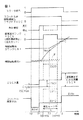
図6は第1の実施例におけるスタータ信号、スロットル弁閉制御実行フラグFTHVC、燃料噴射、掃気実行フラグFSCV、機関始動後カウンタCNT、機関回転数Ne、ISC流量、及び、スロットル弁開度θthの推移を示すタイムチャートである。
スロットル弁閉制御実行フラグFTHVCが“1”の状態の時に、時刻T0でスタータ信号の値が1になって機関1が始動状態となると、この時点では燃料の噴射が実行されていないので、スロットル弁開度θthは第1の開度θth1 に設定される。その後、時刻T1までのクランキング中は、スロットル弁3が略全閉の開度θth1 のまま必要最小限のISC流量ISCmin が流れる。
【0038】
機関1のクランキング中の時刻T1において燃料噴射が行われると、アイドル時のISC流量の学習値ISCGがRAM104から読み出されて機関1の運転状態パラメータで補正されてISC流量ISCHが計算される。そして、このISC流量ISCHを流すためのスロットル弁3の開度θthが開度θth2 に設定される。
【0039】
この状態で機関1が正常に始動する時は、時刻T1の後に所定時間クランキングが続行された後に機関の回転数Ne が実線で示すように増大し始める。この後の時刻T2において機関回転数Ne が所定回転数Nesに達すると、機関始動後カウンタCNTがカウントを開始する。この状態ではスロットル弁3が開度θth2 のままISC流量ISCHが流れる。この後、時刻T3において機関始動後カウンタCNTが所定値Cに達すると、スロットル弁閉制御実行フラグFTHVCが“0”にされ、ISC流量は通常の算出式で計算され、スロットル弁開度θthは、算出された通常のISC流量に応じたスロットル弁開度θthv に設定され、それに応じたISC流量ISCNが流れる。
【0040】
一方、スロットル弁3の開度θthが開度θth2 に設定された燃料の噴射状態において機関1が正常に始動しない時は、時刻T1の後も点線Fで示すように、クランキングが続行され、機関の回転数Ne は増大しない。この状態では、クランキングが開始された時刻T0から基準時間MNが経過した時刻T0+MNにおいて掃気実行フラグFSCVが“1”になる。第1の実施例では、掃気実行フラグFSCVが“1”になると、燃料噴射が破線で示すように停止されると共に、燃焼室内の点火プラグの点火カットが実行される。
【0041】
このように、時刻T0+MNにおいて掃気実行フラグFSCVが“1”になって掃気制御が実行される掃気モードになると、スロットル弁開度θthの値が破線で示すように開度θtho に設定される。この開度θtho はスロットル弁3を全開にする開度、あるいはそれに近い開度である。この結果、時刻T0+MN以後においてISC流量として破線で示す多量の吸気量ISCOが流れる。この掃気モードは、掃気制御が所定時間Lだけ継続した時刻T0+MXに打ち切られる(ここで、MX=MN+Lである)。
【0042】
掃気モードの終了後は、スロットル弁開度θthは元の開度θth2 に戻され、通常の制御が実行される。このように、この実施例では、機関の始動時のスロットル弁閉制御の実行中に掃気制御が行われる時は、スロットル弁3が一時的に全開状態になるので、掃気制御が損なわれることがない。
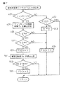
図7は機関1の始動時の電子制御スロットル弁3の開度設定の手順の第2の実施例を示すフローチャートである。図7に示すルーチンも所定時間毎、例えば、数ms毎に実行される。第1の実施例では、掃気実行フラグFSCVが“1”に設定されると、燃料噴射が停止されると共に燃焼室内の点火プラグによる点火も停止されていた。一方、図7に示す第2の実施例では、掃気実行フラグFSCVが“1”に設定されると、燃料噴射は停止されるが、燃焼室内の点火プラグの点火カットは行われない。
【0043】
従って、第2の実施例では、掃気モード中に燃焼室内の空燃比が適正になった時点で点火によって燃焼室内の燃料に着火し、機関1が始動することがある。このような場合、掃気モードではスロットル弁3が全開、或いは全開に近い状態まで開いているので、機関回転数Neが急激に上昇してしまう可能性がある。第2の実施例は、この掃気モード中の機関1の始動による機関回転数Neの過度の上昇を防止するものである。
【0044】
このため、第2の実施例においては、図5においてステップ401から408で説明した掃気実行フラグFSCVの設定手順の後に、機関回転数Neの過度の上昇を防止する手順を追加している。従って、図7に示すフローチャートのステップ401から408の手順は図5で説明したフローチャートと全く同じであるので、ここではその説明を省略する。
【0045】
第2の実施例では、ステップ408で掃気実行フラグFSCVが“1”に設定された後に、ステップ701において機関回転数Neを読み込む。そして、続くステップ702において、機関回転数Neが基準回転数Neref以上になったか否かを判定する。機関回転数Neが基準回転数Neref未満の場合は機関が始動していないと判定してこのままこのルーチンを終了する。一方、ステップ702において機関回転数Neが基準回転数Neref以上となった場合は機関が始動したと判定してステップ703に進み、掃気実行フラグFSCVを“0”に設定して掃気モードを打ち切る。この制御により、掃気モード中に機関が始動したとしても、機関回転数Neが過度に上昇するおそれがない。
【0046】
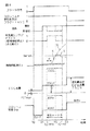
図8は第2の実施例におけるスタータ信号、スロットル弁閉制御実行フラグFTHVC、燃料噴射、掃気実行フラグFSCV、機関始動後カウンタCNT、機関回転数Ne、ISC流量、及び、スロットル弁開度θthの推移を示すタイムチャートである。
時刻T0から時刻T0+MNまでのスタータ信号、スロットル弁閉制御実行フラグFTHVC、燃料噴射状態、掃気実行フラグFSCV、機関回転数Ne、ISC流量、及び、スロットル開度θthは、第1の実施例と全く同じである。そして、第1の実施例では、時刻T0+MNの後、機関回転数Neが増大しないために、時刻T0+MXまで掃気モードが継続されていた。
【0047】
ところが、第2の実施例では、時刻T0+MNから所定時間Rの経過後の掃気モード中に機関1が始動してしまい、破線Sで示すように機関回転数Neが増大し、時刻TSにおいて機関回転数Neが基準回転数Nerefに達している。このまま掃気モードが継続されると、機関回転数Neは二点鎖線Uで示すように過度に増大するおそれがあるので、第2の実施例では、時刻TSの時点で掃気実行フラグFSCVが“0”に設定される。
【0048】
このように、第2の実施例では、掃気実行フラグFSCVが“1”になって掃気制御が実行される掃気モード中に機関1が始動した場合には、スロットル弁開度θthの値が開度θtho から開度θth2 に戻されるので、ISC流量も元の流量ISCHに戻ることになり、機関の回転数Ne は破線Vで示すように増大しなくなる。
【0049】
以上のように、本発明では実施例において説明したように、機関の始動時にスロットル弁の閉弁制御を行う多気筒内燃機関において掃気制御が実行される場合には、スロットル弁の閉弁制御が一時的に解除されるので、掃気制御がスムーズに行われることになり、スロットル弁の閉弁制御による機関の始動性の向上及びエミッション悪化の防止と、掃気制御を両立させることができる。
【0050】
なお、以上説明した実施例では、内燃機関の吸気通路の閉鎖を電子制御スロットル弁3により行うものについて説明を行ったが、電子制御スロットル弁3の代わりに、電子制御される吸気制御弁が吸気通路に別に設けられているものについても本発明を有効に適用することができる。
【0051】
【発明の効果】
以上説明したように、本発明の内燃機関の吸気制御装置によれば、電子制御開閉弁が吸気通路に設けられた多気筒内燃機関であって機関の始動時に電子制御開閉弁の閉弁制御を行うものにおいて、掃気制御の実行時にはスロットル弁の閉弁制御を一時的に解除するようにしたので、スロットル弁の閉弁制御による機関の始動性の向上及びエミッション悪化の防止と、掃気制御を両立させることができるという効果がある。
また、掃気制御実行中に機関回転数が基準値まで増大した時には、掃気が停止されると共に、開閉弁の開度がISC開度に設定されるので、機関回転数が暴走することなく機関を始動させることができるという効果がある。
【図面の簡単な説明】
【図1】本発明の一実施例の吸気制御装置が搭載された電子制御式多気筒内燃機関の構成を示す構成図である。
【図2】スロットル弁の閉制御を実行するフラグの設定手順を示すフローチャートである。
【図3】スロットル弁の閉制御を実行するフラグのリセットを示すフローチャートである。
【図4】掃気制御実行フラグの設定手順を示すフローチャートである。
【図5】本発明の始動時の電子制御スロットル弁の開度設定の手順の第1の実施例の手順を示すフローチャートである。
【図6】第1の実施例におけるスタータ信号、スロットル弁閉制御実行フラグ、燃料噴射状態、掃気実行フラグ、機関始動後カウンタ、機関回転数、ISC流量、及びスロットル弁開度の推移を示すタイムチャートである。
【図7】本発明の始動時の電子制御スロットル弁の開度設定の手順の第2の実施例の手順を示すフローチャートである。
【図8】第2の実施例におけるスタータ信号、スロットル弁閉制御実行フラグ、燃料噴射状態、掃気実行フラグ、機関始動後カウンタ、機関回転数、ISC流量、及びスロットル弁開度の推移を示すタイムチャートである。
【符号の説明】
2…吸気通路
3…スロットル弁
4…スロットルモータ
5…スロットル開度センサ
8…燃料噴射弁
10…ECU
17…イグニッションスイッチ
18…大気圧センサ
19…スタータ
20…スタータ駆動回路
21…クランク位置センサ
23…リングギヤ
24…タイミングロータ
25…信号歯
26…欠歯部[0001]
TECHNICAL FIELD OF THE INVENTION
The present invention relates to an intake control apparatus for an internal combustion engine, and more particularly, to an intake control apparatus for an internal combustion engine in which valve closing control of an electronic control throttle valve is performed when the engine is started, and scavenging control of unburned fuel in a combustion chamber is performed when starting is difficult. Equipment related.
[0002]
[Prior art]
In recent years, with the development of computers, electronically controlled internal combustion engines that attempt to electronically optimally control the rotation speed of the internal combustion engine have been put to practical use. As electronic control of such internal combustion engines, for example, fuel injection amount control, ignition timing control, control of the opening timing of intake and exhaust valves, and the like have been preceded. You are in the stage. In an internal combustion engine that electronically controls the opening of the throttle valve, the opening of the throttle valve can be set regardless of the amount of depression of the accelerator pedal.
[0003]
For this reason, it has been proposed to use an electronically controlled throttle valve to close the intake passage when the engine is started, thereby reducing the amount of intake air at the start and increasing the intake pipe negative pressure to promote the vaporization of fuel. I have. This is because, in an electronically controlled internal combustion engine, fuel is not sufficiently atomized at the time of startup because the fuel injection valve is mounted in the intake passage near each combustion chamber, and the startability is deteriorated at this time. This is to prevent the user from doing so.
[0004]
On the other hand, in the case of an electronically controlled fuel injection type internal combustion engine, when the engine does not easily start at the time of a cold start of the engine or the like and the starting failure occurs due to excessive fuel injection, the fuel injection is performed while the cranking is continued. There is a technique for stopping and scavenging unburned fuel in a combustion chamber to improve startability. This scavenging control technique is disclosed, for example, in Japanese Patent Application Laid-Open Nos. 5-231213 and 5-321714.
[0005]
[Problems to be solved by the invention]
However, when applying the above-described scavenging control technology to an internal combustion engine that controls the closing of the throttle valve at the time of starting in order to promote fuel vaporization at the time of starting the engine, scavenging control is performed with the throttle valve closed. Therefore, there was a problem that the scavenging could not be performed sufficiently and the poor starting could not be eliminated.
[0006]
Therefore, the present invention is a multi-cylinder internal combustion engine in which an electronically controlled on-off valve is provided in an intake passage, performs valve closing control of the electronically controlled on-off valve when the engine is started, and performs scavenging control when the engine is not properly started. In the internal combustion engine, it is possible to achieve both valve closing control of the electronically controlled on-off valve at the time of starting and scavenging control at the time of poor starting, to improve the startability of the engine, and to prevent emission deterioration. It is intended to provide an intake control device.
[0007]
[Means for Solving the Problems]
According to a first aspect of the present invention, which achieves the above object, there is provided an intake system for an internal combustion engine which includes an electronically controlled opening / closing valve in an intake passage, and performs a valve closing control at the start of the internal combustion engine. In the control device, scavenging means for stopping fuel injection during cranking and performing scavenging of unburned fuel in the combustion chamber, and at start-up for stopping valve closing control at the time of starting the on-off valve when scavenging is being performed Valve closing control stopping meansAnd monitor the engine speed during scavenging, and when the engine speed exceeds the reference value during scavenging, stop the operation of the scavenging means and the valve closing control stopping means at start. Means for resuming valve closing control at the start of the on-off valveAre provided.
[0008]
A second aspect of the present invention that achieves the above object is:An intake control device for an internal combustion engine that has an electronically controlled on-off valve in the intake passage and controls the on-off valve to a fully closed position when the internal combustion engine is started. , The atmospheric pressure correction coefficient, the operating state parameter of the operating state of the auxiliary equipment of the engine are read, and based on the read operating state parameter, the learning value of the ISC flow rate at the time of engine idling is corrected to calculate the ISC flow rate of the engine. Opening setting means for setting the opening of the on-off valve to the ISC opening at which the ISC flow rate flows, and counting the cranking time. When the counted value exceeds a predetermined value, the fuel injection during the cranking is stopped. Scavenging means for scavenging unburned fuel in the combustion chamber, and, when scavenging is being performed, stopping valve closing control at the start of the on-off valve to open the on-off valve to an ISC opening or more. Close at start The control stop means and the engine speed during scavenging are monitored, and when the engine speed exceeds a reference value during scavenging, the operation of the scavenging means and the valve closing control stopping means at start-up is performed. And restarting the valve closing control at the start of the on-off valve and setting the opening of the on-off valve to the ISC opening.It is characterized by having been provided.
[0009]
First form, A cranking time detecting means for detecting a cranking time of the engine may be provided, and the scavenging means may be operated when a count value of the cranking time detecting means exceeds a predetermined value.
First or secondIn the embodiment, the valve closing control stopping means at the time of starting can bring the on-off valve into the fully open state when stopping the valve closing control at the time of starting.
[0010]
According to the first aspect of the present invention, an internal combustion engine that performs valve closing control of an electronically controlled on-off valve when starting the engineEven when the engine is started with the throttle valve open while the scavenging control is performed at the time of poor starting and the ignition is continued even during the execution of the scavenging control, the engine speed is set to the reference value. When the value has increased, the closing control of the throttle valve is restarted, so that the engine can be started without the engine speed running awaybe able to.
According to the second aspect of the present invention, an internal combustion engine that performs valve closing control of an electronically controlled on-off valve when the engine is startedEven when the engine is started with the throttle valve open while the scavenging control is performed at the time of poor starting and the ignition is continued even during the execution of the scavenging control, the engine speed is set to the reference value. When the value has increased, the scavenging is stopped and the opening of the on-off valve is set to the ISC opening, so that the engine is started without runaway of the engine speed.be able to.
[0011]
BEST MODE FOR CARRYING OUT THE INVENTION
Hereinafter, embodiments of the present invention will be described in detail with reference to the accompanying drawings based on specific examples.
FIG. 1 schematically shows an electronically controlled fuel injection type multi-cylinder
[0012]
An
[0013]
Further, a
[0014]
The
[0015]
The engine speed Ne is obtained by measuring the interval (time) of the predetermined crank angle signal CA. The
[0016]
In a conventional internal combustion engine, a
[0017]
On the other hand, in this embodiment, the
In this embodiment, when the
[0018]
Therefore, when starting the
[0019]
Here, the procedure of the drive control of the
FIG. 2 is a flowchart showing a procedure for setting a flag FTHVC for executing the closing control of the electronic
[0020]
In this control, first, in step 201, the engine water temperature THW detected by the
[0021]
In this embodiment, the throttle valve closing control execution flag FTHVC is set to "0" and the throttle valve closing control is not executed when the water temperature THW is lower than the very low temperature of A.degree. This is to increase the reliability of the engine's startability at the present time.If the control accuracy is increased by increasing the cost, the throttle valve closing control at the time of the start will be affected by the water temperature condition of the engine. It can also be performed independently.
[0022]
In this way, the throttle valve closing control execution flag FTHVC that is set to “1” when the water temperature THW is in the range of A ≦ THW ≦ B when the
[0023]
In this control, first, at step 301, the engine speed Ne is read. The engine speed Ne can be calculated from the crank position signal from the
[0024]
On the other hand, if the engine speed Ne is equal to or higher than the set speed Nes in
[0025]
FIG. 4 is a flowchart showing a procedure for setting the scavenging control execution flag FSCV in the
[0026]
In setting the scavenging control execution flag FSCV, first, it is determined in
[0027]
On the other hand, if it is determined in
[0028]
If it is determined in
[0029]
In
[0030]
As described above, in this embodiment, when the
As described with reference to FIG. 2, the setting procedure of the scavenging control execution flag FSCV described in FIG. 4 is based on the fact that the throttle valve is closed when the water temperature THW is lower than the very low temperature of A ° C. and when the water temperature exceeds the very high temperature of B ° C. This corresponds to an embodiment in which the control execution flag FTHVC is set to "0" and the throttle valve closing control is not executed. On the other hand, as described above, when the closing control of the throttle valve at the time of starting is performed irrespective of the water temperature condition of the engine, the setting procedure of the scavenging control execution flag FSCV includes, when the water temperature THW of the engine is extremely low, For example, a condition for setting the scavenging control execution flag FSCV to “1” only when the temperature is lower than A ° C. may be added.
[0031]
FIG. 5 is a flowchart showing a first embodiment of the procedure for setting the opening of the electronically controlled
[0032]
In the first embodiment, first, in
If it is determined in
[0033]
On the other hand, if it is determined in
When the intake air has been sucked into the combustion chamber, but the fuel has not been injected yet, the process proceeds to step 506. In
[0034]
On the other hand, if it is determined in
[0035]
In the next step 508, the throttle valve opening θth2 for flowing the ISC flow rate ISCH calculated in
In
[0036]
In
[0037]
FIG. 6 shows the starter signal, throttle valve closing control execution flag FTHVC, fuel injection, scavenging execution flag FSCV, counter CNT after engine start, engine speed Ne, ISC flow rate, and throttle valve opening θth in the first embodiment. It is a time chart which shows transition.
When the value of the starter signal becomes 1 at time T0 and the
[0038]
When fuel injection is performed at time T1 during cranking of the
[0039]
When the
[0040]
On the other hand, when the
[0041]
As described above, when the scavenging execution flag FSCV is set to “1” at the time T0 + MN to enter the scavenging mode in which the scavenging control is executed, the value of the throttle valve opening θth is set to the opening θtho as indicated by the broken line. The opening degree θtho is an opening degree at which the
[0042]
After the end of the scavenging mode, the throttle valve opening θth is returned to the original opening θth2, and normal control is performed. As described above, in this embodiment, when the scavenging control is performed during the execution of the throttle valve closing control when the engine is started, the scavenging control may be impaired because the
FIG. 7 is a flowchart showing a second embodiment of the procedure for setting the opening of the electronically controlled
[0043]
Therefore, in the second embodiment, when the air-fuel ratio in the combustion chamber becomes appropriate during the scavenging mode, the fuel in the combustion chamber may be ignited by ignition, and the
[0044]
Therefore, in the second embodiment, a procedure for preventing an excessive increase in the engine speed Ne is added after the setting procedure of the scavenging execution flag FSCV described in
[0045]
In the second embodiment, after the scavenging execution flag FSCV is set to "1" in
[0046]
FIG. 8 shows a starter signal, a throttle valve closing control execution flag FTHVC, a fuel injection, scavenging execution flag FSCV, a counter CNT after engine start, an engine speed Ne, an ISC flow rate, and a throttle valve opening θth in the second embodiment. It is a time chart which shows transition.
The starter signal from the time T0 to the time T0 + MN, the throttle valve closing control execution flag FTHVC, the fuel injection state, the scavenging execution flag FSCV, the engine speed Ne, the ISC flow rate, and the throttle opening θth are completely the same as those in the first embodiment. Is the same. In the first embodiment, after the time T0 + MN, the scavenging mode is continued until the time T0 + MX because the engine speed Ne does not increase.
[0047]
However, in the second embodiment, the
[0048]
As described above, in the second embodiment, when the
[0049]
As described above, in the present invention, as described in the embodiment, when the scavenging control is executed in the multi-cylinder internal combustion engine that performs the closing control of the throttle valve at the time of starting the engine, the closing control of the throttle valve is performed. Since the scavenging control is temporarily canceled, the scavenging control is smoothly performed, and the scavenging control can be achieved while improving the startability of the engine and preventing the deterioration of the emission by controlling the closing of the throttle valve.
[0050]
In the embodiment described above, the electronic
[0051]
【The invention's effect】
As described above, according to the intake control apparatus for an internal combustion engine of the present invention, a multi-cylinder internal combustion engine in which an electronic control on / off valve is provided in an intake passage performs valve closing control of the electronic control on / off valve when the engine is started. During the scavenging control, the throttle valve closing control is temporarily released when the scavenging control is executed.Thus, it is possible to improve the engine startability and prevent emission deterioration by the throttle valve closing control, and achieve both scavenging control. There is an effect that can be made.
Further, when the engine speed increases to the reference value during the execution of the scavenging control, scavenging is stopped, and the opening of the on-off valve is set to the ISC opening. There is an effect that it can be started.
[Brief description of the drawings]
FIG. 1 is a configuration diagram showing a configuration of an electronically controlled multi-cylinder internal combustion engine equipped with an intake control device according to one embodiment of the present invention.
FIG. 2 is a flowchart showing a procedure for setting a flag for executing a throttle valve closing control.
FIG. 3 is a flowchart showing resetting of a flag for executing a throttle valve closing control.
FIG. 4 is a flowchart showing a setting procedure of a scavenging control execution flag.
FIG. 5 is a flowchart showing a procedure of a first embodiment of a procedure for setting an opening degree of an electronically controlled throttle valve at the time of starting according to the present invention.
FIG. 6 is a time chart showing transitions of a starter signal, a throttle valve closing control execution flag, a fuel injection state, a scavenging execution flag, a counter after engine start, an engine speed, an ISC flow rate, and a throttle valve opening degree in the first embodiment. It is a chart.
FIG. 7 is a flowchart showing a procedure of a second embodiment of the procedure for setting the opening of the electronically controlled throttle valve at the time of starting according to the present invention.
FIG. 8 is a time chart showing transitions of a starter signal, a throttle valve closing control execution flag, a fuel injection state, a scavenging execution flag, a counter after engine start, an engine speed, an ISC flow rate, and a throttle valve opening degree in the second embodiment. It is a chart.
[Explanation of symbols]
2. Intake passage
3. Throttle valve
4 ... Throttle motor
5 ... Throttle opening sensor
8. Fuel injection valve
10 ... ECU
17 ... Ignition switch
18. Atmospheric pressure sensor
19 ... Starter
20 Starter drive circuit
21 ... Crank position sensor
23 ... Ring gear
24 ... Timing rotor
25 ... signal tooth
26 ... tooth missing part
Claims (4)
クランキング中の燃料噴射を停止して燃焼室内の未燃焼燃料の掃気を実行する掃気手段と、
掃気が実行されている時には前記開閉弁の始動時の閉弁制御を停止する始動時の閉弁制御停止手段と、
掃気が実行されている時の機関回転数を監視し、掃気実行中に機関回転数が基準値を越えて増大した時には、前記掃気手段と前記始動時の閉弁制御停止手段の動作を停止して前記開閉弁の始動時の閉弁制御を再開する始動時の閉弁制御再開手段と、を設けたことを特徴とする内燃機関の吸気制御装置。An intake control device for an internal combustion engine that includes an electronically controlled opening / closing valve in an intake passage and performs valve closing control at the time of starting to control the opening / closing valve to a fully closed position at the time of starting the internal combustion engine.
Scavenging means for stopping fuel injection during cranking and performing scavenging of unburned fuel in the combustion chamber;
When the scavenging is being performed, valve closing control stopping means at the time of starting to stop the valve closing control at the time of starting the on-off valve,
The engine speed during scavenging is monitored, and when the engine speed exceeds a reference value during scavenging, the operations of the scavenging means and the valve closing control stopping means at the start are stopped. An intake control device for an internal combustion engine , further comprising: means for restarting valve closing control at the time of starting which restarts valve closing control at the time of starting the on-off valve .
クランキング中の燃料噴射時に、大気圧、大気圧補正係数、機関の補機の動作状態の運転状態パラメータを読み込み、読み込んだ運転状態パラメータに基づいて機関アイドル時のISC流量の学習値を補正して機関のISC流量を算出し、算出したISC流量を流すISC開度に前記開閉弁の開度を設定する開度設定手段と、
前記クランキング時間を計数し、その計数値が所定値を越えた時に、クランキング中の燃料噴射を停止して、燃焼室内の未燃焼燃料の掃気を実行する掃気手段 と、
掃気が実行されている時には前記開閉弁の始動時の閉弁制御を停止して、前記開閉弁の開度を前記ISC開度以上に開く始動時の閉弁制御停止手段と、
掃気が実行されている時の機関回転数を監視し、掃気実行中に機関回転数が基準値を越えて増大した時には、前記掃気手段と前記始動時の閉弁制御停止手段の動作を停止して、前記開閉弁の始動時の閉弁制御を再開し、前記開閉弁の開度を前記ISC開度に設定する始動時の閉弁制御再開手段と、を設けたことを特徴とする内燃機関の吸気制御装置。 An intake control device for an internal combustion engine that includes an electronically controlled opening / closing valve in an intake passage and performs valve closing control at the time of starting to control the opening / closing valve to a fully closed position at the time of starting the internal combustion engine.
At the time of fuel injection during cranking, the atmospheric pressure, the atmospheric pressure correction coefficient, and the operating state parameters of the operating state of the auxiliary equipment of the engine are read, and the learning value of the ISC flow rate at the time of engine idling is corrected based on the read operating state parameters. Opening degree setting means for calculating the ISC flow rate of the engine, and setting the opening degree of the on-off valve to the ISC opening degree at which the calculated ISC flow rate flows;
Scavenging means for counting the cranking time, stopping the fuel injection during cranking when the counted value exceeds a predetermined value, and performing scavenging of unburned fuel in the combustion chamber ,
When the scavenging is being performed, valve closing control at the start of the on-off valve is stopped, and valve-closing control stopping means at the start of opening the opening of the on-off valve to the ISC opening or more,
The engine speed during scavenging is monitored, and when the engine speed exceeds a reference value during scavenging, the operations of the scavenging means and the valve closing control stopping means at the start are stopped. An internal combustion engine comprising: a valve-closing control restarting means for restarting valve closing control at the time of starting the on-off valve and setting the opening of the on-off valve to the ISC opening. Intake control device.
Priority Applications (4)
| Application Number | Priority Date | Filing Date | Title |
|---|---|---|---|
| JP06488099A JP3552575B2 (en) | 1999-03-11 | 1999-03-11 | Intake control device for internal combustion engine |
| DE60019984T DE60019984T2 (en) | 1999-01-29 | 2000-01-28 | Suction control system for internal combustion engine |
| US09/493,602 US6338331B1 (en) | 1999-01-29 | 2000-01-28 | Intake air control system for internal combustion engine |
| EP00101789A EP1024273B1 (en) | 1999-01-29 | 2000-01-28 | Intake air control system for internal combustion engine |
Applications Claiming Priority (1)
| Application Number | Priority Date | Filing Date | Title |
|---|---|---|---|
| JP06488099A JP3552575B2 (en) | 1999-03-11 | 1999-03-11 | Intake control device for internal combustion engine |
Publications (2)
| Publication Number | Publication Date |
|---|---|
| JP2000265880A JP2000265880A (en) | 2000-09-26 |
| JP3552575B2 true JP3552575B2 (en) | 2004-08-11 |
Family
ID=13270882
Family Applications (1)
| Application Number | Title | Priority Date | Filing Date |
|---|---|---|---|
| JP06488099A Expired - Fee Related JP3552575B2 (en) | 1999-01-29 | 1999-03-11 | Intake control device for internal combustion engine |
Country Status (1)
| Country | Link |
|---|---|
| JP (1) | JP3552575B2 (en) |
Families Citing this family (7)
| Publication number | Priority date | Publication date | Assignee | Title |
|---|---|---|---|---|
| JP4912471B2 (en) * | 2006-10-26 | 2012-04-11 | ボルボ ラストバグナー アーベー | Internal combustion engine for use with pressurized low viscosity fuel |
| JP4980270B2 (en) * | 2008-03-10 | 2012-07-18 | 富士重工業株式会社 | Engine start control device |
| JP5525275B2 (en) * | 2010-02-05 | 2014-06-18 | 本田技研工業株式会社 | Scavenging control device for internal combustion engine |
| JP5577183B2 (en) | 2010-08-05 | 2014-08-20 | ヤンマー株式会社 | Gas engine scavenging operation method |
| US8843262B2 (en) | 2010-12-22 | 2014-09-23 | Toyota Jidosha Kabushiki Kaisha | Vehicle, method for controlling vehicle, and device for controlling vehicle |
| JP6003936B2 (en) | 2014-03-25 | 2016-10-05 | トヨタ自動車株式会社 | Control device for internal combustion engine |
| KR102157828B1 (en) * | 2018-10-25 | 2020-09-21 | 콘티넨탈 오토모티브 시스템 주식회사 | Apparatus and method for controlling breather control valve of combustion engine |
-
1999
- 1999-03-11 JP JP06488099A patent/JP3552575B2/en not_active Expired - Fee Related
Also Published As
| Publication number | Publication date |
|---|---|
| JP2000265880A (en) | 2000-09-26 |
Similar Documents
| Publication | Publication Date | Title |
|---|---|---|
| US7661403B2 (en) | Start controller for internal combustion engine | |
| US7233856B2 (en) | Internal combustion engine and control method therefor | |
| JP2004232539A (en) | Engine rotation stop control means | |
| JP2000310144A (en) | Control device for internal combustion engine | |
| JP3552575B2 (en) | Intake control device for internal combustion engine | |
| JP3758235B2 (en) | Intake control device for internal combustion engine | |
| JP3675035B2 (en) | Fuel injection amount control device for internal combustion engine | |
| JP2008163790A (en) | Control device for internal combustion engine | |
| JP2004027914A (en) | Control device for internal combustion engine | |
| US6640763B2 (en) | Apparatus for controlling starting of internal combustion engine | |
| JP3552573B2 (en) | Control device for intake air volume of internal combustion engine | |
| JP2018105164A (en) | Device for controlling internal combustion engine | |
| JP3598863B2 (en) | Intake control device for internal combustion engine | |
| JP4722676B2 (en) | Fuel injection control device for multi-cylinder engine | |
| JP2010084516A (en) | Control device for engine with supercharger | |
| JP2004052613A (en) | Control device for engine | |
| JP3436173B2 (en) | Intake control device for internal combustion engine | |
| JP3478175B2 (en) | Engine speed control device for internal combustion engine | |
| JP3478170B2 (en) | Idle speed control device for internal combustion engine | |
| JP4103314B2 (en) | Control device for internal combustion engine | |
| JP3713998B2 (en) | Intake control device for internal combustion engine | |
| JP2004197693A (en) | Air/fuel ratio control system of internal combustion engine | |
| JPS611841A (en) | Fuel injection device for internal-combustion engine | |
| JP3613662B2 (en) | Intake control device for internal combustion engine | |
| JP3496575B2 (en) | Internal combustion engine speed control device |
Legal Events
| Date | Code | Title | Description |
|---|---|---|---|
| TRDD | Decision of grant or rejection written | ||
| A01 | Written decision to grant a patent or to grant a registration (utility model) |
Free format text: JAPANESE INTERMEDIATE CODE: A01 Effective date: 20040413 |
|
| A61 | First payment of annual fees (during grant procedure) |
Free format text: JAPANESE INTERMEDIATE CODE: A61 Effective date: 20040426 |
|
| R150 | Certificate of patent or registration of utility model |
Free format text: JAPANESE INTERMEDIATE CODE: R150 |
|
| FPAY | Renewal fee payment (event date is renewal date of database) |
Free format text: PAYMENT UNTIL: 20080514 Year of fee payment: 4 |
|
| FPAY | Renewal fee payment (event date is renewal date of database) |
Free format text: PAYMENT UNTIL: 20090514 Year of fee payment: 5 |
|
| FPAY | Renewal fee payment (event date is renewal date of database) |
Free format text: PAYMENT UNTIL: 20100514 Year of fee payment: 6 |
|
| FPAY | Renewal fee payment (event date is renewal date of database) |
Free format text: PAYMENT UNTIL: 20110514 Year of fee payment: 7 |
|
| FPAY | Renewal fee payment (event date is renewal date of database) |
Free format text: PAYMENT UNTIL: 20110514 Year of fee payment: 7 |
|
| FPAY | Renewal fee payment (event date is renewal date of database) |
Free format text: PAYMENT UNTIL: 20120514 Year of fee payment: 8 |
|
| LAPS | Cancellation because of no payment of annual fees |