JP3545140B2 - Bearing and manufacturing method thereof - Google Patents
Bearing and manufacturing method thereof Download PDFInfo
- Publication number
- JP3545140B2 JP3545140B2 JP26635796A JP26635796A JP3545140B2 JP 3545140 B2 JP3545140 B2 JP 3545140B2 JP 26635796 A JP26635796 A JP 26635796A JP 26635796 A JP26635796 A JP 26635796A JP 3545140 B2 JP3545140 B2 JP 3545140B2
- Authority
- JP
- Japan
- Prior art keywords
- bearing
- impregnated
- sintered oil
- cylindrical body
- oil
- Prior art date
- Legal status (The legal status is an assumption and is not a legal conclusion. Google has not performed a legal analysis and makes no representation as to the accuracy of the status listed.)
- Expired - Fee Related
Links
Images


Landscapes
- Sliding-Contact Bearings (AREA)
- Rolling Contact Bearings (AREA)
Description
【0001】
【発明の属する技術分野】
本発明は、回転軸にかかるラジアル方向の荷重を支持するための軸受に関するものである。また、そのような軸受の製造方法に関するものである。
【0002】
【従来の技術】
従来よりラジアル方向の荷重を受けるための滑り軸受の1つとして、焼結含油軸受が知られている。このような焼結含油軸受は、ポーラスなものであり、含浸されたオイルが滲み出すことにより、回転軸との間に油膜を形成することができる。したがって、無給油潤滑可能な軸受として使用されている。
【0003】
上記のような焼結含油軸受は、例えば、図7に示すような形態で使用される。すなわち、焼結含油軸受を備える軸受1は、保持リング2の上下端部に、焼結含油円筒体3、4がそれぞれ配設されて構成されている。この場合、焼結含油円筒体3、4の各内周面3a、4aが、回転軸5の外周面に摺接しており、外周面との間に油膜を形成して軸受面として機能している。
【0004】
しかしながら、上記の軸受1においては、図に示すように、設置時に負荷側(図示矢印X側)において図示矢印Yで示すような微小な軸心ズレがある場合には、回転軸5が片当たりした状態で使用されることになる。よって、焼結含油円筒体3の内周面3aに大きな負荷がかかった状態で使用されることになり、結局、焼結含油円筒体3が摩耗してしまうことになる。
【0005】
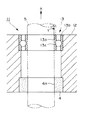
上記欠点を改善するために、図8に示すような構成が考えられる。
すなわち、焼結含油軸受を備える軸受11は、保持リング12の上下端部に、ボールベアリング13、焼結含油円筒体14がそれぞれ配設されて構成されている。ボールベアリング13は、インナーレース13a、アウターレース13b間にボール13cを備えるものである。
【0006】
上記軸受11であると、インナーレース13a、アウターレース13b間に隙間があることから、微小なものであれば、軸心ズレを許容することが可能である。
【0007】
【発明が解決しようとする課題】
しかしながら、上記の軸受11において、軸心ズレがある場合には、インナーレース13aがアウターレース13bに対して傾いた状態で使用されることになり、回転抵抗が大きくなってしまうという問題があった。
また、この構成においては、軸心ズレを微小であれば許容できるものの、その程度が比較的小さいものであった。すなわち、調芯性が小さいという問題があった。
【0008】
本発明は、上記事情に鑑みてなされたもので、軸心ズレがある場合においても回転抵抗を低く維持し得るとともに、調芯性の大きな軸受を提供することを目的とする。
また、上記のような軸受を容易に製造し得る方法を提供することも、また、本発明の目的である。
【0009】
【課題を解決するための手段】
請求項1記載の軸受においては、回転軸にかかるラジアル方向の荷重を支持するための軸受であって、焼結され、含油処理されるとともに、軸線方向の一端部側に位置する内周面が前記回転軸の外周面に摺接して前記回転軸を支持する第1のラジアル軸受部とされた焼結含油円筒体と、該焼結含油円筒体の他端部側に形成された周溝内において、該焼結含油円筒体の内面から径方向内方に突出することにより前記回転軸の外周面を支持する第2のラジアル軸受部を構成した状態で配設された複数の転動体とを具備し、前記焼結含油円筒体の前記他端部側には、端面から前記軸線方向内方に向けて凹む凹所が形成され、該凹所は、前記複数の転動体が配設される前記周溝を形成した状態で押え部材により閉塞され、前記周溝には、前記焼結含油円筒体の径方向内方への前記複数の転動体の飛出を阻止する張出部が形成されていることを特徴としている。
請求項2記載の軸受においては、請求項1記載の軸受において、前記押え部材には、前記焼結含油円筒体の径方向内方への前記複数の転動体の飛出を阻止する張出部が設けられていることを特徴としている。
請求項3記載の軸受においては、請求項1または2記載の軸受において、前記押え部材は、前記焼結含油円筒体よりも硬質の金属からなることを特徴としている。
請求項4記載の軸受においては、請求項1、2または3記載の軸受において、前記焼結含油円筒体の軸線方向一端面には、軸線を同じくしてリング溝が形成されており、該リング溝内には、スラスト用転動体が、前記焼結含油円筒体の端面から軸方向外方に突出することにより前記回転軸にかかるスラスト力を支持し得るよう配設されていることを特徴としている。
【0010】
請求項5記載の軸受の製造方法においては、請求項1ないし4のいずれかに記載の軸受を製造するための方法であって、予め、前記凹所が形成された前記焼結含油円筒体と、前記複数の転動体と、前記押え部材とを準備しておき、前記焼結含油円筒体内にガイド棒を挿入し、前記複数の転動体を前記凹所内に投入し、前記押え部材を前記周溝を形成した状態で前記凹所内に固定することを特徴としている。
請求項6記載の軸受の製造方法においては、請求項5記載の軸受の製造方法において、前記ガイド棒は、該ガイド棒を前記焼結含油円筒体内に配置したときに、奥側よりも手前側の開口を広くするよう、先細り形状であることを特徴としている。
【0011】
請求項1記載の発明によると、軸線方向の一端部側および他端部側において、それぞれ第1および第2のラジアル軸受部により、ラジアル方向の荷重の支持を行う。第1のラジアル軸受部においては、焼結含油円筒体の内周面が、焼結含油円筒体から滲み出すオイルにより回転軸との間に油膜を形成して小さな回転抵抗で支持を行う。また、第2のラジアル軸受部においては、周溝内に配設された複数の転動体が、一方では焼結含油円筒体から給油されつつ他方では回転軸の外周面上を転がりつつ小さな回転抵抗で支持を行う。
ここで、軸心ズレが存在している場合でも、第2のラジアル軸受部においては、各転動体において回転軸の外周面との接触点がずれるだけであり、回転抵抗を低く維持したまま支持を行い得ることに変わりはない。よって、調芯性の大きな軸受が得られる。また、焼結含油円筒体の凹所は、周溝を形成した状態で押え部材により閉塞されるので、周溝内に配設される転動体の飛び出しが容易な手段で防止される。また、転動体は、周溝に形成された張出部により、焼結含油円筒体の径方向内方への飛出を阻止される。
請求項2記載の発明によると、押え部材の張出部により、焼結含油円筒体の径方向内方への転動体の飛出が阻止される。
請求項3記載の発明によると、押え部材が、焼結含油円筒体よりも硬質の金属から構成されているので、押え部材は、焼結含油円筒体よりも摩耗が低く抑えられる。周溝は、押え部材と焼結含油円筒体とで形成される空間であるので、押え部材が焼結含油円筒体よりも摩耗が少ないことにより、その分だけ全体的な摩耗が減少する。言い換えれば、押え部材を焼結体で形成する場合に比較して、押え部材を硬質とする分だけ全体的な摩耗が減少する。
請求項4記載の発明によると、焼結含油円筒体の軸線方向一端面に形成されたリング溝内に配設されているスラスト用転動体により、回転軸にかかるスラスト力が支持される。
【0012】
請求項5記載の発明によると、ガイド棒が挿入された焼結含油円筒体の凹所内に転動体を投入するので、転動体は、ガイド棒に案内されて確実に凹所内に投入される。
請求項6記載の発明によると、ガイド棒が先細り形状であるので、ガイド棒を焼結含油円筒体内に配置したときには、奥側よりも手前側の開口が広くなり、凹所内への転動体の投入が容易になされる。
【0013】
【発明の実施の形態】
以下、本発明の実施の形態について、図面を参照して説明する。
【0014】
〔第1実施形態〕
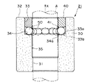
図1は、本発明の軸受の第1実施形態を示すもので、図1において、軸受21は、焼結含油円筒体30、押え部材40、球体(転動体)50を備えて構成されている。
【0015】
焼結含油円筒体30は、粉末を型により所定形状に圧縮成形した後、焼結されることにより形成されたものである。焼結含油円筒体30は、以降の工程において含油処理されることになるが、これについては、製造方法のところで説明する。本発明において、適切な材料としては、例えば、Cu−Sn系、Fe−Cu系、Fe系、ステンレス系、等がある。
焼結含油円筒体30の軸線方向一端部側に位置する内周面は、回転軸Aの外周面に摺接して回転軸Aを支持する第1のラジアル軸受部31とされている。
また、焼結含油円筒体30の他端部側には、端面32から軸線方向内方に向けて凹む凹所33が形成されている。
ここで、凹所33の底部には、環状に凹む形状の油溜凹部33aが形成されている。油溜凹部33aは、符号33bで示す位置および形状、あるいは、同様の形状であっても良い。
【0016】
押え部材40は、焼結含油円筒体30よりも硬質の金属から形成されており、周溝34を形成した状態で、凹所33を閉塞するよう固定されている。
【0017】
球体50は、スチールボール、セラミックボール、等の比較的硬質の材料から形成されるもので、周溝34内に配設されている。この場合、球体50は、複数のものが隙間なく配設されている。また、球体50は、焼結含油円筒体30の内面35よりも径方向内方に突出した状態で、かつ、内周側の先端の包絡線が第1のラジアル軸受部31のなす面の延長上に位置した状態で配設されている。これにより、球体50は、回転軸Aの外周面を支持する第2のラジアル軸受部を構成している。
また、球体50の内周側への飛出は、焼結含油円筒体30の張出部34a、および、押え部材40の張出部41により阻止されている。
【0018】
上記構成を有する軸受21は、図示矢印X側を軸心ズレが起こりやすい負荷側として設置されることが好ましい。
【0019】
上記構成を有する軸受21においては、軸線方向の一端部側および他端部側において、それぞれ第1および第2のラジアル軸受部により、ラジアル方向の荷重の支持を行うことができる。第1のラジアル軸受部31においては、焼結含油円筒体30から滲み出すオイルにより、焼結含油円筒体30の内周面と回転軸Aの外周面との間に油膜を形成し、小さな回転抵抗で支持を行う。また、複数の球体50により形成されている第2のラジアル軸受部においては、周溝34内に配設された複数の球体50が、一方では焼結含油円筒体30から給油されることにより、他方では回転軸Aの外周面上を転がることにより、二重の意味において、小さな回転抵抗で支持を行うことができる。
この場合、焼結含油円筒体30は、従来例を示す図7、8と比較することで明らかなように、大きなバルク体であることにより、十分な量のオイルを含有しており、第1および第2のラジアル軸受部に対して十分な量のオイルを供給することができる。
【0020】
次に、負荷側(図示矢印X側)において軸心ズレが存在している場合について説明する。
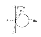
この場合には、回転軸Aが正規位置から傾斜することになるが、複数の球体50により形成されている第2のラジアル軸受部においては、図2に示すように、各球体において回転軸Aの外周面との接触点がP1 からP2 へとずれるだけであって、球体50が受ける荷重の大きさに変わりはない。また、図示の球体50以外の球体についても、接触点の変位量および向きが変わるだけであり、状況は同様であることは、容易に理解される。
したがって、軸受21においては、軸心ズレがある場合でも、回転抵抗を低く維持したまま支持を行い得ることができ、結局、調芯性の大きな軸受が得られることになる。
【0021】
上記軸受21は、このような効果を有していることにより、オーディオ・VTR装置、事務機器、産業機器、等におけるキャプスタンモータ、スピンドルモータ、マイクロモータ、等の各種モータの回転軸、あるいは、他の部材の回転軸の支持において、有効に適用することができる。これ以外の任意の回転軸の支持に適用しても良いことは、もちろんである。
【0022】
また、焼結含油円筒体30の凹所33は、周溝34を残した状態で押え部材40により閉塞されるので、周溝34内に配設される球体50の飛び出しを容易な手段で防止することができる。
【0023】
さらに、押え部材40が、焼結含油円筒体30よりも硬質の金属から構成されているので、押え部材を焼結体で形成する場合に比較して、押え部材40を硬質とする分だけ全体的な摩耗を減少させ、長寿命化を図ることができる。
【0024】
また、上記軸受21は、自己給油性を有している。
すなわち、第1および第2ののラジアル軸受部に対しては、自身のバルク内にオイルを含有している焼結含油円筒体30から十分な量のオイルを供給することができる。
【0025】
また、上記軸受21は、ノイズレスである。
すなわち、図8に示したボールベアリングと比較すると明らかなように、ボールベアリングの場合に発生するようなボールの転がり音は、発生しない。しかも、摺動面(第1のラジアル軸受部31の内周面)において発生する摺動音は、焼結含油円筒体30が多孔質体であることから、振動を減衰させて吸収することができる。
このような、振動減衰機能は、第2のラジアル軸受部における球体50の転がり音に対しても効果的であり、球体50の転がり音を有効に減衰させて消音することができる。結局、軸受21は、ノイズレスである。
【0026】
また、上記軸受21は、省スペースに寄与する。
すなわち、第1のラジアル軸受部31においては、摺動面があるだけで良い。また、第2のラジアル軸受部においては、球体50を周溝34内に配設するだけで良い。よって、図8に示したボールベアリングと比較すると明らかなように、部品点数が少なくて済み、省スペースに寄与する。
【0027】
また、凹所33には、油溜凹部33aが形成されているので、余分なオイルを貯留することができ、余分なオイルが無用に流出することを防止することができる。また、必要に応じて、油溜凹部33aから球体50へとオイルを供給することができる。
【0028】
次に、上記軸受21の製造方法について、図3を参照して説明する。
【0029】
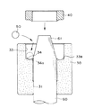
まず、予め準備しておいた焼結含油円筒体30内に、第1のラジアル軸受部31の内径とほぼ等しい外径を有しかつ図示のように先端61が先細り形状とされたガイド棒60を挿入する。
そして、複数の球体50を凹所33内に投入する。
さらに、押え部材40を周溝34を形成した状態で凹所33内に圧入・固定する。
最後に、軸受21全体を真空状態に置き、含油させる。
これにより、軸受21の製造を完了する。
【0030】
この場合、押え部材40の凹所33内への圧入・固定を効果的に達成するために、押え部材40の外径を、凹所33の径よりもわずかに大きめに形成しておくことが好ましい。
【0031】
上記の製造方法においては、ガイド棒60が挿入された焼結含油円筒体30の凹所33内に球体50を投入するので、少々荒っぽく球体50を投入したにしても、球体50を、ガイド棒60に案内させて確実に凹所33内に投入することができ、容易に軸受21を製造することができる。
【0032】
また、ガイド棒60の先端61が先細り形状であるので、ガイド棒60を焼結含油円筒体30内に配置したときには、奥側よりも手前側の開口が広くなって、凹所33内への球体50の投入を容易に行うことができる。
また、ガイド棒60が先細り形状であるので、ガイド棒60の焼結含油円筒体30内への挿入も、また容易である。
【0033】
〔第2実施形態〕
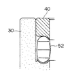
図4は、本発明の軸受の第2実施形態を示すものである。本実施形態が、上記第1実施形態と大きく相違するのは、
▲1▼焼結含油円筒体30の軸線方向端面36には、軸線を同じくしてリング溝37が形成されていること、
▲2▼リング溝37内には、スラスト用球体(スラスト用転動体)80が、焼結含油円筒体30の端面36から軸方向外方に突出した状態に、かつ、リング溝37から飛び出し不可能に配設されていること、
▲3▼負荷側(図示矢印X側)が図示下方に設定されていること、
のみである。本実施形態において、上記第1実施形態と同様の部材については、同一符号を付し、その説明を省略する。
【0034】
スラスト用球体80は、球体50と同様の材料から構成されているとともに、リング溝37内において複数のものが隙間なく配設されている。
【0035】
複数のスラスト用球体80は、回転軸Aに一体に固定されたカラーA1 の下面を支持しており、カラーA1 が下向きのスラスト力を受けながら回転したときに、一方では焼結含油円筒体30から給油されることにより、他方ではカラーA1 の下面上を転がることにより、二重の意味において、小さな抵抗でスラスト方向の支持を行うことができる。
すなわち、軸体71においては、ラジアル方向に加えて、スラスト方向の支持をも行うことができる。
【0036】
なお、本発明は、上記実施形態に限定されるものではなく、以下の形態とすることもできる。
a)転動体を図1に示すような球体50とすることに代えて、図5に示すような半球どうしが円柱体で連結された形状のコロ51とすること、または、図6に示すような紡錘形状のコロ52とすること。あるいは、楕円形状のコロとすること。
b)スラスト用転動体を図4に示すようなスラスト用球体80とすることに代えて、適切な形状のコロとすること。
c)押え部材40を焼結含油円筒体30よりも硬質の材料から形成することに代えて、焼結含油円筒体30と同じ材料から形成すること、あるいは、任意の材料から形成すること。
d)焼結含油円筒体30に対して真空含油させることに代えて、浸漬等、他の任意の含油方法を適用すること。
e)軸受21(あるいは71)を組み上げてから、含油させることに代えて、任意の時点において含油させること。
f)球体を任意の材質から構成すること。
g)複数の球体50を周溝34内において、隙間なく配設することに代えて、隙間を許容して配設すること。
h)複数のスラスト用球体80をリング溝37内において、隙間なく配設することに代えて、隙間を許容して配設すること。
i)スラスト用球体80を第1のラジアル軸受部31側に設けることに代えて、第2のラジアル軸受部31側、または、負荷設置側に設けること。
j)第1のラジアル軸受部31に代えて、球体からなるラジアル軸受部を使用すること。
【0037】
【発明の効果】
本発明の軸受およびその製造方法によれば、以下の効果を奏する。
請求項1記載の軸受によれば、軸線方向の一端部側および他端部側において、それぞれ第1および第2のラジアル軸受部により、ラジアル方向の荷重の支持を行う。特に、第2のラジアル軸受部においては、軸心ズレが存在している場合でも、各球体において回転軸の外周面との接触点がずれるだけであり、変わりなく、回転抵抗を低く維持したまま支持を行うことができる。よって、調芯性の大きな軸受を得ることができる。また、焼結含油円筒体の凹所は、周溝を形成した状態で押え部材により閉塞されるので、周溝内に配設される球体の飛び出しを容易な手段で防止することができる。また、転動体は、周溝に形成された張出部により、焼結含油円筒体の径方向内方への飛出を阻止される。
請求項2記載の軸受によれば、押え部材の張出部により、焼結含油円筒体の径方向内方への転動体の飛出が阻止される。
請求項3記載の軸受によれば、押え部材が、焼結含油円筒体よりも硬質の金属から構成されているので、押え部材を焼結体で形成する場合に比較して、押え部材を硬質とする分だけ全体的な摩耗を減少させ、長寿命化を図ることができる。請求項4記載の軸受によれば、焼結含油円筒体の軸線方向一端面に形成されたリング溝内に配設されているスラスト用球体により、回転軸にかかるスラスト力を支持することができ、ラジアル方向に加えて、スラスト方向の支持をも行うことができる。
【0038】
請求項5記載の軸受の製造方法によれば、ガイド棒が挿入された焼結含油円筒体の凹所内に球体を投入するので、球体を、ガイド棒に案内させて確実に凹所内に投入することができ、容易に上記軸受を製造することができる。
請求項6記載の軸受の製造方法によれば、ガイド棒が先細り形状であるので、ガイド棒を焼結含油円筒体内に配置したときには、奥側よりも手前側の開口が広くなって、凹所内への球体の投入を容易に行うことができる。
また、ガイド棒が先細り形状であるので、ガイド棒の焼結含油円筒体内への挿入も、また容易である。
【図面の簡単な説明】
【図1】本発明の軸受の第1実施形態を示す断面図である。
【図2】図1に示す軸受における球体を取り出して、回転軸に軸心ズレがある場合の作用を説明するための説明図である。
【図3】図1に示す軸受の製造方法を説明するための説明図である。
【図4】本発明の軸受の第2実施形態を示す断面図である。
【図5】本発明の軸受の変形形態を示す断面図である。
【図6】本発明の軸受の他の変形形態を示す断面図である。
【図7】従来の軸受の構成例を示す断面図である。
【図8】従来の軸受の他の構成例を示す断面図である。
【符号の説明】
A 回転軸
21 軸受
30 焼結含油円筒体
31 第1のラジアル軸受部
32 端面
33 凹所
34 周溝
35 内面
36 端面
37 リング溝
40 押え部材
50 球体(転動体)
51 コロ(転動体)
52 コロ(転動体)
60 ガイド棒
80 スラスト用球体(スラスト用転動体)[0001]
TECHNICAL FIELD OF THE INVENTION
The present invention relates to a bearing for supporting a radial load applied to a rotating shaft. The invention also relates to a method for manufacturing such a bearing.
[0002]
[Prior art]
Conventionally, a sintered oil-impregnated bearing is known as one of the sliding bearings for receiving a load in a radial direction. Such a sintered oil-impregnated bearing is porous, and an oil film can be formed between the sintered oil-impregnated bearing and the rotating shaft by seeping out the impregnated oil. Therefore, it is used as a bearing that can be lubricated without lubrication.
[0003]
The sintered oil-impregnated bearing as described above is used, for example, in a form as shown in FIG. That is, the bearing 1 including the sintered oil-impregnated bearing is configured by arranging the sintered oil-impregnated
[0004]
However, in the above bearing 1, as shown in the figure, when there is a slight misalignment as shown by the arrow Y on the load side (the arrow X side in the figure) at the time of installation, the
[0005]
In order to improve the above drawback, a configuration as shown in FIG. 8 can be considered.
That is, the bearing 11 including the sintered oil-impregnated bearing is configured such that the ball bearing 13 and the sintered oil-impregnated cylindrical body 14 are disposed at the upper and lower ends of the
[0006]
In the case of the bearing 11, since there is a gap between the
[0007]
[Problems to be solved by the invention]
However, in the above bearing 11, when there is an axial misalignment, the
Further, in this configuration, although the axial center deviation can be tolerated as small as possible, the degree is relatively small. That is, there was a problem that the alignment was small.
[0008]
The present invention has been made in view of the above circumstances, and it is an object of the present invention to provide a bearing that can maintain a low rotational resistance even when there is an axial misalignment and that has large alignment.
It is also an object of the present invention to provide a method by which such bearings can be easily manufactured.
[0009]
[Means for Solving the Problems]
The bearing according to claim 1, which is a bearing for supporting a radial load applied to the rotating shaft, wherein the inner peripheral surface located at one end side in the axial direction is sintered and subjected to oil impregnation processing. A sintered oil-impregnated cylindrical body serving as a first radial bearing portion that slides on the outer peripheral surface of the rotary shaft and supports the rotary shaft; and a circumferential groove formed on the other end side of the sintered oil-impregnated cylindrical body. And a plurality of rolling elements disposed in a state of constituting a second radial bearing portion for supporting an outer peripheral surface of the rotating shaft by projecting radially inward from an inner surface of the sintered oil-impregnated cylindrical body. A recess is formed on the other end side of the sintered oil-impregnated cylindrical body, the recess being recessed inward from the end face in the axial direction, and the recess is provided with the plurality of rolling elements. The peripheral groove is closed by a pressing member in a state where the peripheral groove is formed. It is characterized in that projecting portion that prevents the flying unloading of the plurality of rolling elements in the radial inward direction of the cylindrical body is formed.
In the bearing according to
According to a third aspect of the present invention, in the bearing according to the first or second aspect, the pressing member is made of a metal harder than the sintered oil-impregnated cylindrical body.
In the bearing according to the fourth aspect, in the bearing according to the first, second or third aspect, a ring groove having the same axis is formed on one end surface of the sintered oil-impregnated cylindrical body in the axial direction. In the groove, a thrust rolling element is disposed so as to be able to support a thrust force applied to the rotating shaft by projecting axially outward from an end face of the sintered oil-impregnated cylindrical body. I have.
[0010]
A method for manufacturing a bearing according to
In the method for manufacturing a bearing according to claim 6, in the method for manufacturing a bearing according to
[0011]
According to the first aspect of the present invention, the radial load is supported by the first and second radial bearings at one end and the other end in the axial direction. In the first radial bearing portion, the inner peripheral surface of the sintered oil-impregnated cylindrical body forms an oil film between itself and the rotating shaft by oil oozing out of the sintered oil-impregnated cylindrical body, thereby supporting the sintered oil-impregnated cylindrical body with a small rotational resistance. Further, in the second radial bearing portion, a plurality of rolling elements provided in the circumferential groove are supplied with oil from a sintered oil-impregnated cylindrical body while rolling on the outer peripheral surface of the rotating shaft while having a small rotational resistance. Support with.
Here, even in the case where the axial center misalignment exists, in the second radial bearing portion, only the contact point between each rolling element and the outer peripheral surface of the rotating shaft is shifted, and the second radial bearing is supported while keeping the rotational resistance low. Is still possible. Therefore, a bearing with large alignment can be obtained. Further, since the recess of the sintered oil-impregnated cylindrical body is closed by the pressing member in a state where the circumferential groove is formed, the rolling element disposed in the circumferential groove is prevented from jumping out by an easy means. Further, the rolling element is prevented from projecting radially inward of the sintered oil-impregnated cylindrical body by the projecting portion formed in the circumferential groove.
According to the second aspect of the present invention, the projection of the pressing member prevents the rolling element from jumping inward in the radial direction of the sintered oil-impregnated cylindrical body.
According to the third aspect of the present invention, since the pressing member is made of a metal harder than the sintered oil-impregnated cylindrical body, the wear of the pressing member is suppressed lower than that of the sintered oil-impregnated cylindrical body. Since the circumferential groove is a space formed by the holding member and the sintered oil-impregnated cylindrical body, the wear of the holding member is smaller than that of the sintered oil-impregnated cylindrical body, and accordingly, the overall wear is reduced accordingly. In other words, as compared with the case where the holding member is formed of a sintered body, the overall wear is reduced by the amount by which the holding member is made harder.
According to the invention described in
[0012]
According to the fifth aspect of the present invention, since the rolling element is introduced into the recess of the sintered oil-impregnated cylindrical body into which the guide rod is inserted, the rolling element is guided by the guide rod and is reliably introduced into the recess.
According to the invention as set forth in claim 6, since the guide rod has a tapered shape, when the guide rod is disposed in the sintered oil-impregnated cylinder, the opening on the near side is wider than the back side, and the rolling element is inserted into the recess. Input is made easily.
[0013]
BEST MODE FOR CARRYING OUT THE INVENTION
Hereinafter, embodiments of the present invention will be described with reference to the drawings.
[0014]
[First Embodiment]
FIG. 1 shows a first embodiment of the bearing of the present invention. In FIG. 1, the
[0015]
The sintered oil-impregnated
The inner peripheral surface of the sintered oil-impregnated
On the other end side of the sintered oil-impregnated
Here, at the bottom of the
[0016]
The holding
[0017]
The
Further, the projection of the
[0018]
It is preferable that the
[0019]
In the
In this case, the sintered oil-impregnated
[0020]
Next, the case where the axial center deviation exists on the load side (the arrow X side in the drawing) will be described.
In this case, the rotation axis A is inclined from the normal position. However, in the second radial bearing portion formed by the plurality of
Therefore, the bearing 21 can be supported while maintaining a low rotational resistance even when the shaft center is displaced. As a result, a bearing having a large alignment can be obtained.
[0021]
The
[0022]
Further, since the
[0023]
Further, since the holding
[0024]
The
That is, a sufficient amount of oil can be supplied to the first and second radial bearings from the sintered oil-impregnated
[0025]
The
That is, as is apparent from comparison with the ball bearing shown in FIG. 8, the rolling noise of the ball as occurs in the case of the ball bearing does not occur. Moreover, the sliding sound generated on the sliding surface (the inner peripheral surface of the first radial bearing portion 31) can be absorbed by attenuating the vibration because the sintered oil-impregnated
Such a vibration damping function is also effective for the rolling sound of the
[0026]
The
That is, the first
[0027]
In addition, since the oil reservoir concave
[0028]
Next, a method of manufacturing the
[0029]
First, a
Then, the plurality of
Further, the pressing
Finally, the
Thereby, the manufacture of the
[0030]
In this case, in order to effectively press-fit and fix the holding
[0031]
In the above manufacturing method, since the
[0032]
Further, since the
In addition, since the
[0033]
[Second embodiment]
FIG. 4 shows a second embodiment of the bearing of the present invention. This embodiment is significantly different from the first embodiment in that:
(1) A
(2) In the
(3) The load side (arrow X side in the figure) is set downward in the figure;
Only. In the present embodiment, the same members as those in the first embodiment are denoted by the same reference numerals, and description thereof will be omitted.
[0034]
The
[0035]
The plurality of
That is, the shaft 71 can support not only the radial direction but also the thrust direction.
[0036]
Note that the present invention is not limited to the above-described embodiment, and may be configured as follows.
a) Instead of using the rolling element as a
b) Instead of using a
c) Instead of forming the holding
d) Instead of vacuum-impregnating the sintered oil-impregnated
e) Instead of assembling the bearing 21 (or 71) and then impregnating it, impregnate it at any time.
f) The sphere is made of any material.
g) Instead of arranging the plurality of
h) Instead of disposing the plurality of
i) Instead of providing the
j) Instead of the first
[0037]
【The invention's effect】
According to the bearing and the method of manufacturing the same of the present invention, the following effects can be obtained.
According to the bearing of the first aspect, the radial load is supported by the first and second radial bearing portions on one end side and the other end side in the axial direction, respectively. In particular, in the second radial bearing portion, even when the axial center deviation exists, only the point of contact with the outer peripheral surface of the rotating shaft in each sphere shifts, and the rotational resistance remains unchanged and the rotational resistance is kept low. Support can be provided. Therefore, a bearing with large alignment can be obtained. Further, since the recess of the sintered oil-impregnated cylindrical body is closed by the pressing member in a state where the circumferential groove is formed, it is possible to prevent the sphere provided in the circumferential groove from jumping out by an easy means. Further, the rolling element is prevented from projecting radially inward of the sintered oil-impregnated cylindrical body by the projecting portion formed in the circumferential groove.
According to the bearing of the second aspect, the projection of the pressing member prevents the rolling element from jumping inward in the radial direction of the sintered oil-impregnated cylindrical body.
According to the bearing of the third aspect, since the pressing member is made of a metal harder than the sintered oil-impregnated cylindrical body, the pressing member is harder than when the pressing member is formed of a sintered body. Accordingly, the overall wear can be reduced and the life can be extended. According to the bearing described in
[0038]
According to the bearing manufacturing method of the fifth aspect, since the sphere is put into the recess of the sintered oil-impregnated cylindrical body into which the guide rod is inserted, the sphere is guided by the guide rod and is put into the recess surely. The bearing can be easily manufactured.
According to the bearing manufacturing method of the sixth aspect, since the guide rod has a tapered shape, when the guide rod is disposed in the sintered oil-impregnated cylinder, the opening on the near side is wider than the back side, and the inside of the recess is formed. It is possible to easily insert a sphere into the sphere.
Since the guide rod has a tapered shape, it is easy to insert the guide rod into the sintered oil-impregnated cylinder.
[Brief description of the drawings]
FIG. 1 is a sectional view showing a first embodiment of a bearing of the present invention.
FIG. 2 is an explanatory diagram for explaining an operation in a case where a sphere in the bearing shown in FIG.
FIG. 3 is an explanatory diagram for explaining a method of manufacturing the bearing shown in FIG. 1;
FIG. 4 is a sectional view showing a second embodiment of the bearing of the present invention.
FIG. 5 is a sectional view showing a modified form of the bearing of the present invention.
FIG. 6 is a sectional view showing another modification of the bearing of the present invention.
FIG. 7 is a cross-sectional view showing a configuration example of a conventional bearing.
FIG. 8 is a cross-sectional view showing another configuration example of a conventional bearing.
[Explanation of symbols]
A Rotating
51 Rollers (rolling elements)
52 rollers (rolling element)
60
Claims (6)
焼結され、含油処理されるとともに、軸線方向の一端部側に位置する内周面が前記回転軸の外周面に摺接して前記回転軸を支持する第1のラジアル軸受部とされた焼結含油円筒体と、
該焼結含油円筒体の他端部側に形成された周溝内において、該焼結含油円筒体の内面から径方向内方に突出することにより前記回転軸の外周面を支持する第2のラジアル軸受部を構成した状態で配設された複数の転動体とを具備し、
前記焼結含油円筒体の前記他端部側には、端面から前記軸線方向内方に向けて凹む凹所が形成され、
該凹所は、前記複数の転動体が配設される前記周溝を形成した状態で、押え部材により閉塞され、
前記周溝には、前記焼結含油円筒体の径方向内方への前記複数の転動体の飛出を阻止する張出部が形成されていることを特徴とする軸受。A bearing for supporting a radial load applied to the rotating shaft,
Sintered and oil-impregnated, and the inner peripheral surface located at one end side in the axial direction slides on the outer peripheral surface of the rotating shaft to form a first radial bearing portion that supports the rotating shaft. An oil-impregnated cylinder,
A second groove for supporting the outer peripheral surface of the rotary shaft by projecting radially inward from the inner surface of the sintered oil-impregnated cylinder in a circumferential groove formed on the other end side of the sintered oil-impregnated cylinder; A plurality of rolling elements arranged in a state of constituting a radial bearing portion ,
On the other end side of the sintered oil-impregnated cylinder, a recess is formed that is recessed inward in the axial direction from an end face,
The recess is closed by a pressing member in a state in which the peripheral groove in which the plurality of rolling elements are provided is formed,
A bearing characterized in that a projecting portion for preventing the plurality of rolling elements from jumping inward in the radial direction of the sintered oil-impregnated cylindrical body is formed in the circumferential groove .
前記押え部材には、前記焼結含油円筒体の径方向内方への前記複数の転動体の飛出を阻止する張出部が設けられていることを特徴とする軸受。The bearing according to claim 1,
A bearing, wherein the pressing member is provided with an overhang portion for preventing the plurality of rolling elements from jumping inward in the radial direction of the sintered oil-impregnated cylindrical body .
前記焼結含油円筒体の軸線方向一端面には、軸線を同じくしてリング溝が形成されており、該リング溝内には、スラスト用転動体が、前記焼結含油円筒体の端面から軸方向外方に突出することにより前記回転軸にかかるスラスト力を支持し得るよう配設されていることを特徴とする軸受。The bearing according to claim 1, 2 or 3,
A ring groove is formed along one axis in the axial direction of the sintered oil-impregnated cylinder, and a thrust rolling element is formed in the ring groove from the end face of the sintered oil-impregnated cylinder. A bearing provided so as to be able to support a thrust force applied to the rotating shaft by projecting outward in the direction.
予め、前記凹所が形成された前記焼結含油円筒体と、前記複数の転動体と、前記押え部材とを準備しておき、
前記焼結含油円筒体にガイド棒を挿入し、
前記複数の転動体を前記凹所内に投入し、
前記押え部材を前記周溝を形成した状態で前記凹所内に固定することを特徴とする軸受の製造方法。A method for manufacturing a bearing according to any one of claims 1 to 4, comprising:
In advance, the sintered oil-impregnated cylindrical body in which the recess is formed, the plurality of rolling elements, and the pressing member are prepared,
Insert a guide rod into the sintered oil-impregnated cylinder,
Throwing the plurality of rolling elements into the recess,
A method of manufacturing a bearing, wherein the holding member is fixed in the recess with the peripheral groove formed.
Priority Applications (1)
| Application Number | Priority Date | Filing Date | Title |
|---|---|---|---|
| JP26635796A JP3545140B2 (en) | 1996-10-07 | 1996-10-07 | Bearing and manufacturing method thereof |
Applications Claiming Priority (1)
| Application Number | Priority Date | Filing Date | Title |
|---|---|---|---|
| JP26635796A JP3545140B2 (en) | 1996-10-07 | 1996-10-07 | Bearing and manufacturing method thereof |
Publications (2)
| Publication Number | Publication Date |
|---|---|
| JPH10110724A JPH10110724A (en) | 1998-04-28 |
| JP3545140B2 true JP3545140B2 (en) | 2004-07-21 |
Family
ID=17429826
Family Applications (1)
| Application Number | Title | Priority Date | Filing Date |
|---|---|---|---|
| JP26635796A Expired - Fee Related JP3545140B2 (en) | 1996-10-07 | 1996-10-07 | Bearing and manufacturing method thereof |
Country Status (1)
| Country | Link |
|---|---|
| JP (1) | JP3545140B2 (en) |
Families Citing this family (2)
| Publication number | Priority date | Publication date | Assignee | Title |
|---|---|---|---|---|
| CN101915268B (en) * | 2010-08-26 | 2012-07-25 | 友达光电股份有限公司 | Bearing combination and support bracket combination |
| CN109185329B (en) * | 2018-10-23 | 2024-03-29 | 珠海格力节能环保制冷技术研究中心有限公司 | Crankshaft bearing of compressor and compressor |
-
1996
- 1996-10-07 JP JP26635796A patent/JP3545140B2/en not_active Expired - Fee Related
Also Published As
| Publication number | Publication date |
|---|---|
| JPH10110724A (en) | 1998-04-28 |
Similar Documents
| Publication | Publication Date | Title |
|---|---|---|
| JP2510374B2 (en) | Sliding / rolling bearings with rolling elements | |
| JP2006226400A (en) | Shaft device | |
| JPH0814284B2 (en) | Ceramic bearing | |
| JP3545140B2 (en) | Bearing and manufacturing method thereof | |
| JP2003247540A (en) | Rolling bearing and rod end bearing | |
| JP2501729B2 (en) | Sliding rolling bearing with rolling elements | |
| JPH074439A (en) | High speed angular ball bearing | |
| KR19990045529A (en) | Bearing device with sliding member and holding member made of porous sintered metal impregnated with lubricating oil | |
| JP2002213458A (en) | Cylindrical roller bearing | |
| JP2000120707A (en) | Rolling bearing | |
| JPH09238441A (en) | Small motor shaft supporting structure | |
| GB2271818A (en) | Radial and thrust bearing for electric motor | |
| JP2000055055A5 (en) | ||
| JP3317859B2 (en) | Manufacturing method of bearing | |
| JP2003120684A (en) | Thrust roller bearing | |
| JPH1082424A (en) | Holder for rolling bearing | |
| JPH1182522A (en) | Touchdown bearing for magnetic bearing device | |
| JP2019168020A (en) | Cylindrical roller bearing | |
| JPH0996314A (en) | Sintered bearing and manufacture thereof | |
| US20230053136A1 (en) | Turbocharger | |
| JP3077282U (en) | Magnetic suspension bearing | |
| JP2555374Y2 (en) | Composite bearing | |
| JP2001024044A (en) | Guide roller device | |
| JP3602325B2 (en) | Dynamic pressure type porous oil-impregnated bearing | |
| JPH0545246U (en) | Rolling bearing device |
Legal Events
| Date | Code | Title | Description |
|---|---|---|---|
| TRDD | Decision of grant or rejection written | ||
| A01 | Written decision to grant a patent or to grant a registration (utility model) |
Free format text: JAPANESE INTERMEDIATE CODE: A01 Effective date: 20040330 |
|
| A61 | First payment of annual fees (during grant procedure) |
Free format text: JAPANESE INTERMEDIATE CODE: A61 Effective date: 20040407 |
|
| R150 | Certificate of patent or registration of utility model |
Free format text: JAPANESE INTERMEDIATE CODE: R150 |
|
| S111 | Request for change of ownership or part of ownership |
Free format text: JAPANESE INTERMEDIATE CODE: R313115 |
|
| R350 | Written notification of registration of transfer |
Free format text: JAPANESE INTERMEDIATE CODE: R350 |
|
| LAPS | Cancellation because of no payment of annual fees |