JP3542470B2 - Telescopic leader device for soft ground improvement machine - Google Patents
Telescopic leader device for soft ground improvement machine Download PDFInfo
- Publication number
- JP3542470B2 JP3542470B2 JP24822797A JP24822797A JP3542470B2 JP 3542470 B2 JP3542470 B2 JP 3542470B2 JP 24822797 A JP24822797 A JP 24822797A JP 24822797 A JP24822797 A JP 24822797A JP 3542470 B2 JP3542470 B2 JP 3542470B2
- Authority
- JP
- Japan
- Prior art keywords
- leader
- guide rod
- chain
- reader
- ground improvement
- Prior art date
- Legal status (The legal status is an assumption and is not a legal conclusion. Google has not performed a legal analysis and makes no representation as to the accuracy of the status listed.)
- Expired - Lifetime
Links
Images


Description
【0001】
【発明の属する技術分野】
本発明は軟弱地盤改良機における撹拌ロッドのリーダーに関するものである。
【0002】
【従来の技術】
従来の技術は、
▲1▼現地組立作業によりリーダーと駆動機との接続は、リーダーをほぼ垂直にし駆動機とピンによりドッキングを行っていた為、高所作業が必要であった。
▲2▼地盤改良場所内に電線等が空中にある場所では、電線の移設が必要であった。
▲3▼運搬時、1体物のリーダーならば、分解し短くできない。又、現地組立時に分解可能なリーダー単体ならば現地にて組立が必要であった。
▲4▼強風が発生した時などリーダーを倒すか、分解が必要であった。
▲5▼撹拌ロッドの推進速度を増速することは困難であった。
【0003】
【発明が解決しようとする課題】
本発明はリーダーによる撹拌ロッドの推進速度を向上し、リーダーを伸縮して現地での組立時間を減縮し、高所作業を解消し、分解移動を解消することを目的とする。
【0004】
【課題を解決するための手段】
上記の目的を達成するため本発明は
内蔵油圧シリンダーによって上下段のリーダーが1直線上に伸縮自在であり、下段リーダーを支持体に支持し、上段のリーダーの上端部にリーダーと平行な案内杆の上端部を支持し、案内杆の下端部に設けた係合金具を下段リーダーに設けた案内ガイドに摺動自在に係合し、案内杆の上下端部に設けた小スプロケットに掛回したチエンの端部を下段リーダーの上端部に設けた止め具に接続し、撹拌軸の回動機筐を上記チエンに接続しかつ案内杆に沿って摺動自在に係合してなり、下段リーダー内に上段リーダーを上記油圧シリンダーによって収納可能であり、同時に上記チエンによって上記回動機筐を案内杆に沿って下降可能である軟弱地盤改良機の伸縮リーダー装置
下段リーダーを移動車体による支持体に垂直制御可能に形成した上記第1発明記載の軟弱地盤改良機の伸縮リーダー装置
によって構成される。
【0005】
【発明の実施の形態】
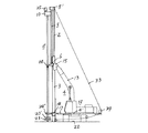
クローラ12の車体4’に設けたブーム13の先端をシリンダー14により伸縮自在に形成して支持体4を形成し、その先端部を下段リーダー3の上部に設けた取付片15にピン16によって枢支し、車体4’の下部に設けたほぼ水平方向の垂直制御シリンダー17の先端部を下段リーダー3の下部ホールダー18に枢支し、前後方向の偏位を垂直に制御する。又下部ホールダー18は図3に示すように左右方向の長方形枠であって、該枠の内部左右に設けた小シリンダー19、19’で下段リーダー3を挟持し、小シリンダー19、19’の伸縮によって下段リーダー3の左右方向の偏位を垂直に制御することができる。
【0006】
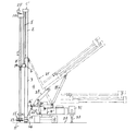
又図6、図7に示すようにクローラ12の車体4’に設けた伸縮自在の前向シリンダー20によって支持体4を形成し、その先端部を下段リーダー3の下部に設けた取付片15’にピン16’によって枢支し、車体4’と下段リーダー3の上部とを2個の傾斜シリンダー21、21によって支持し(図8)、下段リーダー3を垂直方向に支持することができる。そして前向シリンダー20によって下段リーダー3の前後方向の偏位を垂直に制御し、2個の傾斜シリンダー21、21の伸縮によって下段リーダー3の左右方向の偏位を垂直に制御することができる。
【0007】
このようにした下段リーダー3内に上段リーダー2を伸縮自在に嵌合し、両リーダー2、3内に内蔵した油圧シリンダー1によって上段リーダー2を伸縮させ、両リーダー2、3の合計最大長さLから最小長さほぼL/2に伸縮させることができる。
【0008】
上段リーダー2の上端には案内杆5の上端を支持する取付金具5’を設け、該金具5’に上下段リーダー2、3と平行に上記案内杆5を懸垂し、該案内杆5の下端に設けた係合金具6を下段リーダー3に設けた案内ガイド7に摺動自在に係合させる。
【0009】
上記案内杆5の下端は図1に示すように下段リーダー3の上端部分にあって、係合金具6は案内ガイド7の上端部分に係合させる。
【0010】
上記案内杆5の上下端は取付金具5’及び係合金具6にピン5”、6’によって枢支され、ピン5”、6’にはそれぞれ小スプロケット8、8’を設け、小スプロケット8、8’間にチエン9が正逆回動自在に掛回される。
【0011】
上記案内杆5には機筐案内ガイド7’を設け、機筐案内ガイド7’に摺動自在に係合する撹拌軸回動機筐10を配置し、該機筐10を上記チエン9に接続する。
【0012】
上記回動機筐10には撹拌軸11の上端部を支持し、撹拌軸11は内外2重管11’、11”よりなり、機筐10には内外2重管11’、11”を互いに反対方向に回転させる歯車群を内蔵し、機筐10を上段リーダー2の上端部に支持した状態で、内外2重管11’、11”の下端は上下段リーダー2、3の最大長さLの状態において(図1)、地面22に近く配置され内外2重管11’、11”の下端にそれぞれ撹拌羽根23、23’を上下に設けてなるものである。
【0013】
外管11’の中程は係合金具6に突設した中程支持環24に回動自在に支持され、下端部は下段リーダー3の下部に設けた下部支持環24’に回動自在に支持される。
【0014】
又上記チエン9の両端は下段リーダー3の上端部正面に突設した止め具6”、6”に止着させるもので上段リーダー2を昇降させることによって機筐10を案内杆5の上下端間を昇降させることができると同時に案内杆5を上段リーダー2と共に下段リーダー3とほぼ同一高さに下降させることができる(図4)。
【0015】
従って機筐10に設けた駆動モーター25を動作して内外2重管11’、11”を回動し、かつ内蔵シリンダー1を収縮させると上段リーダー2が下降し、スプロケット8、8’が回動し、案内杆5を下降させる。上記チエン9は案内杆5の下降に伴って下降し、同時に機筐10が案内杆5に沿って下降し、機筐10を図1実線で示す最上位置から同図仮想線で示す最下位置に一定の速度で下降し、撹拌羽根23、23’を地中に推進させることができる。
【0016】
勿論その際内管11”の上端からセメントミルクを注入し、下端から地中に排出させて撹拌羽根23、23’でこれを土砂と共に撹拌して地中にソイルセメント柱を形成した後、上記下降動作と逆の動作によって機筐10を図1仮想線位置から実線位置に上昇させ、これを繰返してソイルセメント柱を地中に並設し、地盤を改良することができる。又上段リーダー2を上昇させると上述と逆の動作によって機筐10も上段リーダー2の上端部に上昇する。
【0017】
尚図中26で示すものは下段リーダー3の下端に設けた短い伸縮脚で小シリンダー27によって下段リーダー3を地面に支持する。又28は下段リーダー3の固定用の地中刺入棒、図6、図7中29は下段リーダー3をほぼ45度起立させる起伏腕、30はその起伏用シリンダー、31はパワーユニット、32はアウトリガー、図5中33は上下段リーダー2、3の起伏用ワイヤロープ、34はその駆動用ドラム、図1中35はブーム13の起伏用シリンダーである。
【0018】
【発明の効果】
本発明は上述のように構成したのでリーダーによる撹拌ロッドの推進速度を向上し、上段リーダーを下段リーダー内に収容し得てリーダーの高さ又は長さをほぼ1/2に減少し得て、高所作業を解消し、かつ支持体による移動時にリーダーの長さをほぼ半減し得て分解移動を解消し得る効果がある。
【図面の簡単な説明】
【図1】本発明の伸縮リーダー装置を示す側面図である。
【図2】下降状態の側面図である。
【図3】図2A−A線による平面図である。
【図4】リーダー昇降と回動チエンの関係を示す側面説明図である。
【図5】リーダー起伏用ワイヤロープを示す側面図である。
【図6】リーダー倒伏状態の側面図である。
【図7】起立状態の手順を示す側面図である。
【図8】図7に示すリーダー及びシリンダーの一部斜視図である。
【符号の説明】
1 内蔵油圧シリンダー
2、3 上下段リーダー
4 支持体
4’ 移動車体
5 案内杆
6 係合金具
7 案内ガイド
8、8’ 小スプロケット
9 チエン
10 撹拌軸回動機筐[0001]
TECHNICAL FIELD OF THE INVENTION
The present invention relates to a leader of a stirring rod in a soft ground improvement machine.
[0002]
[Prior art]
Conventional technology is
(1) Due to the on-site assembling work, the connection between the leader and the drive was done almost vertically, and docking was performed with the drive and the pin, so work at a high place was necessary.
(2) In places where electric wires are in the air in the ground improvement site, it was necessary to relocate the electric wires.
(3) When transporting, if it is a one-piece leader, it cannot be disassembled and shortened. In addition, if a single leader can be disassembled at the time of on-site assembly, it must be assembled on-site.
(4) The leader must be defeated or disassembled when a strong wind occurs.
(5) It was difficult to increase the propulsion speed of the stirring rod.
[0003]
[Problems to be solved by the invention]
SUMMARY OF THE INVENTION It is an object of the present invention to improve the propulsion speed of a stir rod by a leader, reduce the time required for on-site assembly by expanding and contracting the leader, eliminate work at heights, and eliminate disassembly and movement.
[0004]
[Means for Solving the Problems]
In order to achieve the above object, the present invention provides a guide rod parallel to the leader, wherein the upper and lower leaders can be extended and retracted in a straight line by a built-in hydraulic cylinder, the lower leader is supported by a support, and the upper leader is parallel to the leader. The upper end of the guide rod is supported, and an engagement fitting provided on the lower end of the guide rod is slidably engaged with a guide provided on the lower leader, and is hung around a small sprocket provided on the upper and lower ends of the guide rod. The end of the chain is connected to a stopper provided at the upper end of the lower leader, and the rotating machine housing of the stirring shaft is connected to the chain and slidably engaged along the guide rod. The upper leader can be accommodated by the hydraulic cylinder, and at the same time, the rotating machine housing can be lowered along the guide rod by the chain. Constituted by the vertical controllably formed stretch reader device soft soil improvement machine of the first invention, wherein.
[0005]
BEST MODE FOR CARRYING OUT THE INVENTION
The
[0006]
As shown in FIGS. 6 and 7, the
[0007]
The
[0008]
At the upper end of the
[0009]
The lower end of the
[0010]
The upper and lower ends of the
[0011]
The
[0012]
The rotating
[0013]
The middle of the
[0014]
Further, both ends of the
[0015]
Therefore, when the
[0016]
Of course, at that time, cement milk is poured from the upper end of the
[0017]
[0018]
【The invention's effect】
Since the present invention is configured as described above, the propulsion speed of the stirring rod by the leader is improved, the upper leader can be accommodated in the lower leader, and the height or length of the leader can be reduced by almost half, There is an effect that the work at a high place can be eliminated, and the length of the leader can be reduced by almost half when moving by the support, so that the disassembly movement can be eliminated.
[Brief description of the drawings]
FIG. 1 is a side view showing a telescopic leader device of the present invention.
FIG. 2 is a side view in a lowered state.
FIG. 3 is a plan view taken along the line AA of FIG. 2;
FIG. 4 is an explanatory side view showing a relationship between a leader elevating / lowering and a rotating chain.
FIG. 5 is a side view showing a leader hoisting wire rope.
FIG. 6 is a side view of the leader lying down.
FIG. 7 is a side view showing a procedure in a standing state.
FIG. 8 is a partial perspective view of the leader and the cylinder shown in FIG. 7;
[Explanation of symbols]
DESCRIPTION OF
Claims (2)
Priority Applications (1)
| Application Number | Priority Date | Filing Date | Title |
|---|---|---|---|
| JP24822797A JP3542470B2 (en) | 1997-09-12 | 1997-09-12 | Telescopic leader device for soft ground improvement machine |
Applications Claiming Priority (1)
| Application Number | Priority Date | Filing Date | Title |
|---|---|---|---|
| JP24822797A JP3542470B2 (en) | 1997-09-12 | 1997-09-12 | Telescopic leader device for soft ground improvement machine |
Publications (2)
| Publication Number | Publication Date |
|---|---|
| JPH1181298A JPH1181298A (en) | 1999-03-26 |
| JP3542470B2 true JP3542470B2 (en) | 2004-07-14 |
Family
ID=17175069
Family Applications (1)
| Application Number | Title | Priority Date | Filing Date |
|---|---|---|---|
| JP24822797A Expired - Lifetime JP3542470B2 (en) | 1997-09-12 | 1997-09-12 | Telescopic leader device for soft ground improvement machine |
Country Status (1)
| Country | Link |
|---|---|
| JP (1) | JP3542470B2 (en) |
Families Citing this family (4)
| Publication number | Priority date | Publication date | Assignee | Title |
|---|---|---|---|---|
| JP5819563B1 (en) * | 2015-07-16 | 2015-11-24 | 株式会社トラバース | Ground improvement unit and ground improvement machine |
| JP6426551B2 (en) * | 2015-07-28 | 2018-11-21 | 太平商工株式会社 | Ground driving method of long pile |
| KR101852474B1 (en) * | 2017-02-21 | 2018-06-11 | (주)세종이엔씨 | Deep mixed apparatus for dcm |
| KR102419449B1 (en) | 2021-10-20 | 2022-07-11 | 지이산업 주식회사 | Leader telescopic driving pile machine |
-
1997
- 1997-09-12 JP JP24822797A patent/JP3542470B2/en not_active Expired - Lifetime
Also Published As
| Publication number | Publication date |
|---|---|
| JPH1181298A (en) | 1999-03-26 |
Similar Documents
| Publication | Publication Date | Title |
|---|---|---|
| JP2016222359A (en) | crane | |
| JP3542470B2 (en) | Telescopic leader device for soft ground improvement machine | |
| CN109763853A (en) | A kind of door frame Anchor Care machine | |
| CN207160107U (en) | A kind of pit-picker | |
| CN116201582A (en) | Fully-mechanized hydraulic support retracting system | |
| CN207673278U (en) | A kind of four arms rock perforating device and the four arm rock puncheres equipped with the device | |
| JP2588764B2 (en) | Caisson excavator | |
| JP4003226B2 (en) | Excavator | |
| JP2736008B2 (en) | Ground improvement machine and method of using the same | |
| CN105927161B (en) | Telescopic combined derrick and its rotation liter and lifting method | |
| CN212105727U (en) | Anchor rod drill carriage | |
| CN216043806U (en) | Connecting rod lifting station man platform of anchor rod drill carriage | |
| KR100236220B1 (en) | A leader equipment for ground excavating able to attach general excavator | |
| JP2002030654A (en) | Transporting and erecting machine for cage | |
| JP2781159B2 (en) | Leader for low space and pile driver equipped with this | |
| CN208024294U (en) | The clamp structure and drilling rod of drilling rod | |
| CN220267741U (en) | Double-arm jumbolter | |
| CN114673518B (en) | Tunneling, anchoring and supporting integrated machine and roadway anchoring and supporting construction method | |
| CN216405406U (en) | Pile driver | |
| JPS5934588Y2 (en) | Rake rotation lifting device for telescopic pipe type dust remover | |
| JPS6241120Y2 (en) | ||
| JPH11270267A (en) | Pile-driver | |
| JP2000318979A (en) | Mobile crane device with assisting jib | |
| JP2023025322A (en) | continuous wall excavator | |
| CA2252452A1 (en) | Portable earth drilling apparatus with telescopic mast |
Legal Events
| Date | Code | Title | Description |
|---|---|---|---|
| A521 | Written amendment |
Free format text: JAPANESE INTERMEDIATE CODE: A523 Effective date: 20040122 |
|
| TRDD | Decision of grant or rejection written | ||
| A01 | Written decision to grant a patent or to grant a registration (utility model) |
Free format text: JAPANESE INTERMEDIATE CODE: A01 Effective date: 20040309 |
|
| A61 | First payment of annual fees (during grant procedure) |
Free format text: JAPANESE INTERMEDIATE CODE: A61 Effective date: 20040331 |
|
| R150 | Certificate of patent or registration of utility model |
Free format text: JAPANESE INTERMEDIATE CODE: R150 |
|
| R250 | Receipt of annual fees |
Free format text: JAPANESE INTERMEDIATE CODE: R250 |
|
| FPAY | Renewal fee payment (event date is renewal date of database) |
Free format text: PAYMENT UNTIL: 20090409 Year of fee payment: 5 |
|
| FPAY | Renewal fee payment (event date is renewal date of database) |
Free format text: PAYMENT UNTIL: 20090409 Year of fee payment: 5 |
|
| FPAY | Renewal fee payment (event date is renewal date of database) |
Free format text: PAYMENT UNTIL: 20100409 Year of fee payment: 6 |
|
| FPAY | Renewal fee payment (event date is renewal date of database) |
Free format text: PAYMENT UNTIL: 20110409 Year of fee payment: 7 |
|
| FPAY | Renewal fee payment (event date is renewal date of database) |
Free format text: PAYMENT UNTIL: 20110409 Year of fee payment: 7 |
|
| FPAY | Renewal fee payment (event date is renewal date of database) |
Free format text: PAYMENT UNTIL: 20130409 Year of fee payment: 9 |
|
| FPAY | Renewal fee payment (event date is renewal date of database) |
Free format text: PAYMENT UNTIL: 20140409 Year of fee payment: 10 |
|
| R250 | Receipt of annual fees |
Free format text: JAPANESE INTERMEDIATE CODE: R250 |
|
| R250 | Receipt of annual fees |
Free format text: JAPANESE INTERMEDIATE CODE: R250 |
|
| R250 | Receipt of annual fees |
Free format text: JAPANESE INTERMEDIATE CODE: R250 |
|
| R250 | Receipt of annual fees |
Free format text: JAPANESE INTERMEDIATE CODE: R250 |
|
| EXPY | Cancellation because of completion of term |