JP3203667U - Camera and wire feeding solutions for circumferential welder systems - Google Patents
Camera and wire feeding solutions for circumferential welder systems Download PDFInfo
- Publication number
- JP3203667U JP3203667U JP2015600142U JP2015600142U JP3203667U JP 3203667 U JP3203667 U JP 3203667U JP 2015600142 U JP2015600142 U JP 2015600142U JP 2015600142 U JP2015600142 U JP 2015600142U JP 3203667 U JP3203667 U JP 3203667U
- Authority
- JP
- Japan
- Prior art keywords
- welding
- camera device
- bracket
- wire guide
- arm portion
- Prior art date
- Legal status (The legal status is an assumption and is not a legal conclusion. Google has not performed a legal analysis and makes no representation as to the accuracy of the status listed.)
- Expired - Fee Related
Links
Images


Classifications
-
- B—PERFORMING OPERATIONS; TRANSPORTING
- B23—MACHINE TOOLS; METAL-WORKING NOT OTHERWISE PROVIDED FOR
- B23K—SOLDERING OR UNSOLDERING; WELDING; CLADDING OR PLATING BY SOLDERING OR WELDING; CUTTING BY APPLYING HEAT LOCALLY, e.g. FLAME CUTTING; WORKING BY LASER BEAM
- B23K9/00—Arc welding or cutting
- B23K9/095—Monitoring or automatic control of welding parameters
- B23K9/0956—Monitoring or automatic control of welding parameters using sensing means, e.g. optical
-
- B—PERFORMING OPERATIONS; TRANSPORTING
- B23—MACHINE TOOLS; METAL-WORKING NOT OTHERWISE PROVIDED FOR
- B23K—SOLDERING OR UNSOLDERING; WELDING; CLADDING OR PLATING BY SOLDERING OR WELDING; CUTTING BY APPLYING HEAT LOCALLY, e.g. FLAME CUTTING; WORKING BY LASER BEAM
- B23K9/00—Arc welding or cutting
- B23K9/02—Seam welding; Backing means; Inserts
- B23K9/028—Seam welding; Backing means; Inserts for curved planar seams
- B23K9/0282—Seam welding; Backing means; Inserts for curved planar seams for welding tube sections
- B23K9/0286—Seam welding; Backing means; Inserts for curved planar seams for welding tube sections with an electrode moving around the fixed tube during the welding operation
-
- B—PERFORMING OPERATIONS; TRANSPORTING
- B23—MACHINE TOOLS; METAL-WORKING NOT OTHERWISE PROVIDED FOR
- B23K—SOLDERING OR UNSOLDERING; WELDING; CLADDING OR PLATING BY SOLDERING OR WELDING; CUTTING BY APPLYING HEAT LOCALLY, e.g. FLAME CUTTING; WORKING BY LASER BEAM
- B23K9/00—Arc welding or cutting
- B23K9/12—Automatic feeding or moving of electrodes or work for spot or seam welding or cutting
- B23K9/122—Devices for guiding electrodes, e.g. guide tubes
-
- B—PERFORMING OPERATIONS; TRANSPORTING
- B23—MACHINE TOOLS; METAL-WORKING NOT OTHERWISE PROVIDED FOR
- B23K—SOLDERING OR UNSOLDERING; WELDING; CLADDING OR PLATING BY SOLDERING OR WELDING; CUTTING BY APPLYING HEAT LOCALLY, e.g. FLAME CUTTING; WORKING BY LASER BEAM
- B23K9/00—Arc welding or cutting
- B23K9/32—Accessories
-
- B—PERFORMING OPERATIONS; TRANSPORTING
- B23—MACHINE TOOLS; METAL-WORKING NOT OTHERWISE PROVIDED FOR
- B23K—SOLDERING OR UNSOLDERING; WELDING; CLADDING OR PLATING BY SOLDERING OR WELDING; CUTTING BY APPLYING HEAT LOCALLY, e.g. FLAME CUTTING; WORKING BY LASER BEAM
- B23K2101/00—Articles made by soldering, welding or cutting
- B23K2101/04—Tubular or hollow articles
- B23K2101/06—Tubes
Abstract
【課題】カメラの焦点を溶接領域に合わせるために様々な調整を行えるカメラ取付装置を連結する円周溶接システムを提供する。【解決手段】ワイヤガイド104、104’及びカメラ装置112、113のためのブラケット105、106を含むカメラ装置及びワイヤガイドシステムに関するシステムに関する。ブラケット105、106は、カメラ装置が円周溶接システム100のための溶接領域Zの位置を向くようにカメラ装置を調節する。具体的には、ブラケット105、106はワイヤガイド104、104’が溶接領域Z上に位置するように支持しながら、溶接領域Z上に位置することができるカメラ装置112、113も支持する。ブラケットはカメラ装置で溶接領域を捉えることを可能にし、溶接領域Z上に位置したままとなるようにワイヤガイド上に中心が置かれる。【選択図】図1Provided is a circumferential welding system for connecting camera mounting devices capable of various adjustments for focusing a camera on a welding region. The present invention relates to a system relating to a camera device and a wire guide system including brackets 105, 106 for wire guides 104, 104 'and camera devices 112, 113. The brackets 105, 106 adjust the camera device so that the camera device faces the position of the welding area Z for the circumferential welding system 100. Specifically, the brackets 105 and 106 support the camera devices 112 and 113 that can be positioned on the welding region Z while supporting the wire guides 104 and 104 ′ on the welding region Z. The bracket allows the camera device to capture the weld area and is centered on the wire guide so as to remain on the weld area Z. [Selection] Figure 1
Description
一般に、本考案は円周溶接システムに関連して用いられるカメラ及び取付装置に関する。より具体的には、本考案は、溶接システムの一部に連結され、カメラの焦点を溶接領域に合わせるために様々な調整を行えるようにするカメラ取付装置に関する。 In general, the present invention relates to cameras and mounting devices used in connection with circumferential welding systems. More specifically, the present invention relates to a camera mounting device that is coupled to a portion of a welding system and that allows various adjustments to focus the camera on the welding area.
工業用途において、溶接は、レイジング(raising)、クラッディング、積み上げ、充填、表面硬化、肉盛、接合及び他の溶接施工を含み得る。湾曲面を持つワークピースを溶接する場合は、円周溶接法(orbital welding process)を用いて溶接ヘッドを回転させ湾曲面に溶接部を適用する場合がある。円周溶接が用いられる最も一般的な例はパイプの溶接である。パイプの溶接は薄肉の適用(thin wall application)を含み得る。その際、溶接ヘッドは2つのワークピースの端部が接合される他方の面の周りを回転する。あるいは、パイプの溶接は深開先形状を含み得る。その場合、接合する2つのパイプの間にできた開先内に溶接電極を伸ばして連続した溶接材のビードを形成して開先を埋め、厚肉パイプを接合する。円周溶接システムは、ワークピースをクランプするか又はワークピース上で支持されるガイドトラック又は固定具に取り付けられ、溶接を供給するために回転される溶接ヘッドを含み得る。円周溶接では、前カメラ(lead cameras)及び/又は後カメラ(trailing cameras)を用いても溶接領域の可視性が限られる場合が多い。 In industrial applications, welding can include raising, cladding, stacking, filling, surface hardening, overlaying, joining and other welding applications. When welding a workpiece having a curved surface, the weld head may be applied to the curved surface by rotating the welding head using an orbital welding process. The most common example where circumferential welding is used is pipe welding. Pipe welding can include thin wall applications. In doing so, the welding head rotates around the other surface where the ends of the two workpieces are joined. Alternatively, the welding of the pipe may include a deep groove shape. In that case, a welding electrode is extended in a groove formed between two pipes to be joined to form a continuous weld material bead to fill the groove, and a thick pipe is joined. A circumferential welding system may include a welding head that is attached to a guide track or fixture that clamps the workpiece or is supported on the workpiece and is rotated to provide welding. In circumferential welding, the visibility of the weld area is often limited even when using front cameras and / or trailing cameras.
ワークピースに関連する深開先形状や湾曲によって円周溶接システムに支障がでることがあり、円周溶接システムに関連する向上技術が必要である。 Circumferential welding systems may be hindered by deep groove shapes and curvatures associated with workpieces, and improved techniques associated with circumferential welding systems are required.
前カメラ及び/又は後カメラで溶接領域の可視性を向上させるために、本考案は請求項1に記載の溶接機システム、請求項10に記載のブラケット及び請求項15に記載の円周溶接システムを提案する。本考案の一実施形態によれば、溶接システムが提供される。当該溶接機システムは:シャーシを有し、ワークピースに取り付けられ、ワークピースに取り付けられたトラックの一部で支持される円周溶接機;及び前記シャーシに連結され、前記ワークピース上に溶接継手を形成するように適合された電極を含む溶接トーチを含む。当該溶接機システムは、溶接ワイヤ源に接続され、ワイヤガイドに、そして前記電極が前記ワークピース上に溶接材を溶着する溶接領域に溶接ワイヤを提供するワイヤ送給装置をさらに含む。一態様によれば、当該溶接機システムは前記シャーシに連結されたブラケットを含み、該ブラケットは:第1の面にある第1のアーム部であって、該第1のアーム部の一部はカメラ装置の焦点を前記溶接領域に合わせるように適合されている、第1のアーム部;及び第2のアーム部であって、該第2のアーム部は、前記第1の面から距離D離れた第2の面にあり、前記カメラ装置の少なくとも一部を受容する凹部を規定するオフセット部を有し、該第2のアーム部は、前記溶接ワイヤを前記溶接領域に提供するために前記ワイヤガイドを前記第1の面に支持するワイヤガイド取付部を含む、第2のアーム部を含む。好ましい実施形態は従属項から導き出され得る。 In order to improve the visibility of the welding area with the front camera and / or the rear camera, the present invention provides a welding machine system according to claim 1, a bracket according to claim 10, and a circumferential welding system according to claim 15. Propose. According to one embodiment of the present invention, a welding system is provided. The welder system includes: a circumferential welder having a chassis, attached to a workpiece and supported by a portion of a track attached to the workpiece; and a weld joint connected to the chassis and on the workpiece A welding torch including an electrode adapted to form The welder system further includes a wire feeder that is connected to a welding wire source, provides a welding wire to a wire guide and to a welding area where the electrode deposits a weld on the workpiece. According to one aspect, the welder system includes a bracket coupled to the chassis, the bracket comprising: a first arm portion on a first surface, wherein a portion of the first arm portion is A first arm portion adapted to focus the camera device on the welding region; and a second arm portion, the second arm portion being a distance D from the first surface. An offset portion on the second surface defining a recess for receiving at least a portion of the camera device, wherein the second arm portion is configured to provide the welding wire to the welding region. A second arm portion including a wire guide mounting portion for supporting a guide on the first surface is included. Preferred embodiments can be derived from the dependent claims.
本考案の一実施形態によれば、溶接機システムにカメラ装置を取り付けるためのブラケットが提供される。当該ブラケットは、第1の面にあり、上部と該上部の反対側の下部とを含む第1のアーム部を含む。当該ブラケットによれば、該下部はカメラ装置の第1の部分を受容するカメラ装置取付部を含み、該カメラ装置は溶接領域に焦点が合うように配置される。当該ブラケットは、第2のアーム部であって、前記第1の面から距離D離れた第2の面にあり、前記カメラ装置の第2の部分を受容する凹部を規定するオフセット部を有し、該第2のアーム部は、前記溶接領域に溶接ワイヤの一部を提供するために前記ワイヤガイドを前記第1の面に支持するワイヤガイド取付部を含む、第2のアーム部をさらに含む。当該ブラケットでは、前記カメラ装置取付部の中心点は前記ワイヤガイド取付部の中心点と同じ面にある。好ましい実施形態は従属項から導き出され得る。 According to an embodiment of the present invention, a bracket for attaching a camera device to a welder system is provided. The bracket is on a first surface and includes a first arm portion including an upper portion and a lower portion opposite to the upper portion. According to the bracket, the lower part includes a camera device mounting portion for receiving the first part of the camera device, and the camera device is arranged to focus on the welding area. The bracket has a second arm portion, which is on a second surface that is a distance D away from the first surface, and has an offset portion that defines a recess that receives the second portion of the camera device. The second arm portion further includes a second arm portion including a wire guide mounting portion that supports the wire guide on the first surface to provide a portion of the welding wire to the welding region. . In the bracket, the center point of the camera device attachment portion is on the same plane as the center point of the wire guide attachment portion. Preferred embodiments can be derived from the dependent claims.
本考案の一実施形態によれば、円周溶接システムが提供される。当該円周溶接システムは:シャーシを有し、ワークピースに取り付けられ、ワークピースに取り付けられたトラックの一部で支持される円周溶接機;及び前記シャーシに連結され、前記ワークピース上に溶接継手を形成するように適合された電極を含む溶接トーチを含む。当該円周溶接機は、溶接ワイヤ源に接続され、ワイヤガイドに、そして前記電極が前記ワークピース上に溶接材を溶着する溶接領域に溶接ワイヤを提供するワイヤ送給装置をさらに含む。当該円周溶接システムによれば、前記シャーシに連結されたブラケットが提供され、該ブラケットは:第1の面にある第1のアーム部であって、該第1のアーム部の一部はカメラ装置の焦点を前記溶接領域に合わせるように適合されている、第1のアーム部;及び第2のアーム部であって、該第2のアーム部は、前記第1の面から距離D離れた第2の面にあり、前記カメラ装置の少なくとも一部を受容する凹部を規定するオフセット部を有し、該第2のアーム部は、前記溶接領域の位置に前記ワイヤガイドを向けるために前記ワイヤガイドを前記第1の面に支持するワイヤガイド取付部を含む、第2のアーム部を含む。当該円周溶接システムでは、前記第2のアーム部は:上部及び該上部の反対側の下部;該上部から前記オフセット部に遷移する第1の遷移部;及び前記オフセット部から前記ワイヤガイド取付部又は該下部のうちの少なくとも一方に遷移する第2の遷移部をさらに含み、前記第1の遷移部、前記オフセット部及び前記第2の遷移部は連続湾曲を形成する。 According to one embodiment of the present invention, a circumferential welding system is provided. The circumferential welding system comprises: a circumferential welder having a chassis, attached to the workpiece and supported by a part of a track attached to the workpiece; and connected to the chassis and welded onto the workpiece A welding torch including an electrode adapted to form a joint; The circumferential welder further includes a wire feeder that is connected to a welding wire source, provides a welding wire to a wire guide and to a welding area where the electrode deposits a weld on the workpiece. According to the circumferential welding system, a bracket connected to the chassis is provided, the bracket being: a first arm portion on a first surface, wherein a portion of the first arm portion is a camera. A first arm portion adapted to focus an apparatus on the welding area; and a second arm portion, the second arm portion being spaced a distance D from the first surface. An offset portion on a second surface defining a recess for receiving at least a portion of the camera device, wherein the second arm portion is adapted to direct the wire guide to the position of the welding region. A second arm portion including a wire guide mounting portion for supporting a guide on the first surface is included. In the circumferential welding system, the second arm part includes: an upper part and a lower part opposite to the upper part; a first transition part that transitions from the upper part to the offset part; and the wire guide attachment part from the offset part. Alternatively, a second transition portion that transitions to at least one of the lower portions is further included, and the first transition portion, the offset portion, and the second transition portion form a continuous curve.
本考案の上記の及び他の目的は、図面、詳細な説明及び添付の請求項に照らして考えることで明らかになる。 These and other objects of the present invention will become apparent when considered in light of the drawings, detailed description and appended claims.
本考案は、特定の部分及び部分の構成において物理的形態を取り得る。その好ましい実施形態を本明細書で詳述し、本願の一部を成す添付の図面に図示する。
本考案の実施形態は、ワイヤガイド及びカメラ装置のためのブラケットを含むカメラ装置及びワイヤガイドシステムに関する方法及びシステムに関する。ブラケットは、カメラ装置が円周溶接システムのための溶接領域の位置を向くようにカメラ装置を調節する。具体的には、ブラケットはワイヤガイドが溶接領域上に位置するように支持しながら、溶接領域上に位置することができるカメラ装置も支持する。ブラケットはカメラ装置で溶接領域を捉えることを可能にし、溶接領域上に位置したままとなるようにワイヤガイド上に中心が置かれる。ブラケットはビデオ/カメラによる溶接領域の可視性が提供されるようにカメラ装置を設置できるようにする一方で、ワイヤ位置の調整により又はワイヤ位置の調整から独立してカメラ装置を調整できるようにする。さらに、ワイヤガイド及びカメラ装置システムはブラケットと、溶接領域から離れる上方に又は溶接領域の方である下方にブラケット(及び取り付けられたカメラ装置及びワイヤガイド)を操作する高さ調整装置とを含むことができる。 Embodiments of the present invention relate to a method and system for a camera apparatus and a wire guide system including a wire guide and a bracket for the camera apparatus. The bracket adjusts the camera device so that the camera device faces the position of the welding area for the circumferential welding system. Specifically, the bracket also supports a camera device that can be positioned on the welding area while supporting the wire guide to be positioned on the welding area. The bracket allows the camera device to capture the weld area and is centered on the wire guide so as to remain positioned on the weld area. The bracket allows the camera device to be installed so as to provide video / camera weld area visibility, while allowing the camera device to be adjusted by adjusting the wire position or independent of the adjustment of the wire position. . Further, the wire guide and camera device system includes a bracket and a height adjustment device that operates the bracket (and attached camera device and wire guide) upward away from or toward the welding region. Can do.
本明細書で使用する「溶接(welding、weld)」という用語(該用語の他の任意の成語要素(formatives)を含む)は、電気アーク(限定されないがサブマージアーク、GMAW、MAG、MIG、TIG溶接又は円周溶接システムで用いられる任意の電気アークを含む)の作用により溶融材を溶着することを意味する。 As used herein, the term “welding” (including any other formatives of the term) refers to an electric arc (including but not limited to submerged arcs, GMAW, MAG, MIG, TIG). It means that the molten material is deposited by the action of any electric arc used in welding or circumferential welding systems.
本願出願時に出願人が知っていた本考案を実施するための最良の形態を解説する目的で以下最良の形態を説明する。実施例及び図面は例示に過ぎず、本考案を限定することを意図したものではない。本考案は請求項の範囲及び精神によって評価される。図面を参照して(図示のものは、本考案の例示の実施形態の解説を目的としたものに過ぎず、本考案を限定することを目的としたものではない)、図1〜図7は、自動又は半自動の溶接機システムと共に用いられるカメラ装置及びワイヤガイド取付システムを示す。溶接機システムの一例は、様々な種類の材料のチューブ又はパイプの接合にしばしば用いられる円周溶接である。例えば、自動機械システムによって溶接されるパイプの周りを周回するのにタングステン不活ガス(TIG)又はガスタングステンアーク溶接(GTAW)溶接トーチが使用され得る。図1〜図2Bは、円周溶接環境で用いられる円周溶接システム100(溶接機、システム及び/又は溶接機システムともいう)の例示の実施形態を示す。円周溶接システム100は、パイプ又はチューブの周囲を移動する溶接トラクター(図示せず)と、溶接電源(図示せず)/コントローラ(図示せず)と、オペレータ制御を提供するペンダント(図示せず)とを含む。
For the purpose of explaining the best mode for carrying out the present invention that the applicant knew at the time of filing this application, the best mode will be described below. The examples and drawings are merely illustrative and are not intended to limit the invention. The invention will be evaluated by the scope and spirit of the claims. Referring to the drawings (the illustrations are merely for the purpose of illustrating exemplary embodiments of the invention and are not intended to limit the invention), FIGS. Figure 2 shows a camera device and wire guide mounting system for use with an automatic or semi-automatic welder system. One example of a welder system is circumferential welding, often used to join tubes or pipes of various types of materials. For example, a tungsten inert gas (TIG) or gas tungsten arc welding (GTAW) welding torch can be used to circulate around pipes that are welded by an automated mechanical system. 1-2B illustrate an exemplary embodiment of a circumferential welding system 100 (also referred to as a welder, system and / or welder system) used in a circumferential welding environment.
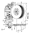
(図1〜図2Bに示すように)システム100は深開先溶接に通常用いられる。図示の例では、溶接機システム100は、ワークピースに取り付けられるか又はトラック上で支持される溶接機本体又はシャーシ101を有する円周TIG溶接機を含む。溶接機システム100は溶接トーチ(概して参照符号30で示す)を含む。溶接トーチは、溶接領域Zに溶接継手を形成するために溶接材を溶着させるための溶接電極32を有する。電極32は、溶接される開先Gに適した電極長さを有する延長電極(extended electrode)である。延長電極32は、所定の深開先溶接に適した10ミリメートル超の長さを含む任意の長さを有し得る。図示の例に示すように、電極長さは100ミリメートル超であり得る。図示の特定例では約120ミリメートルの長さを有する。開先Gの深さに応じて図示のものより長さが大きいか又は小さい電極が使用され得るため、この例に限定されない。
System 100 (as shown in FIGS. 1-2B) is typically used for deep groove welding. In the illustrated example, the
溶接トーチ30は、アルゴンガス等の不活ガスを溶接トーチ30に提供するシールドガス源108に接続されている。シールドガス源108は、シールドガスSを圧力下で貯蔵する円筒等の容器を含み得る。適切なチューブ又は導管を通じたシールドガスSの搬送は調整器又は他のコントローラ107によって制御され得る。非加圧のガス源を、ポンプ等により提供されるガス搬送と共に用いてもよい。厚いプレート又は厚肉鋼管を溶接する場合、溶接継手のデザインは、一連の溶接ビードを継手が充填されるまで積層することによって形成される良好な溶接部が確かに得られるようにするために継手内に細長の電極を設置できるようにし、トーチ角度の調整をある程度可能にする狭開先を通常提供する。下記の説明を通して、このプロセスを区別なく狭開先溶接又は深開先溶接と呼ぶことがある。狭開先溶接は、狭開先又は継手内で単層のビード溶接層を連続的に積層するプロセスである。狭開先環境で考慮すべき点の1つは、十分なシールドガスを維持して溶融溶接溜まりを大気汚染から保護することである。一般に、アルゴン等の不活シールドガスは、シールドガス源の下の開先内に伸びた長い電極を用いて溶接継手外から提供される。
The
溶接機は、スプール103等の溶接ワイヤ源に接続され、1つ以上のワイヤガイド104’、104にタングステンワイヤWを提供するワイヤ送給装置を含み得る。図示の例では、一対の延在したワイヤガイド104’、104が設けられており、シャーシ101の両側に位置する個々のスプール103によってそれらにワイヤが供給される。延在したワイヤガイド104’、104は、第1のカメラ装置及びワイヤガイドシステム(第1の取付システム105とも呼ぶ)及び第2のカメラ装置及びワイヤガイドシステム(第2の取付システム106とも呼ぶ)上でそれぞれ支持されている。第1のカメラ装置及びワイヤガイドシステム及び第2のカメラ装置及びワイヤガイドシステムのそれぞれは、電極32の横方向外側にあり且つワークピース又はパイプPの上にある。ワイヤガイド104’、104は、電極32及び溶接領域Zに向かって内方且つ下方に延在している。例示の溶接機はトラック上で支持されており、ワイヤガイド104’、104が溶接電極32に対してリード位置及びラグ位置に位置している状態で、パイプの周りを移動するトラクタにより駆動される。第1の取付システム105は、第1の取付システム105を溶接領域Zの方に又は溶接領域Zから遠ざかる方に調整できるようにする高さ調整装置130に連結されている。高さ調整装置130は、溶接機システム100のシャーシ101の一部に連結された支持部材132にさらに連結されている。同様に、第2の取付システム106は、第2の取付システム106を溶接領域Zの方に又は溶接領域Zから遠ざかる方に調整できるようにする高さ調整装置124に連結されている。高さ調整装置124は、溶接機システム100のシャーシ101の一部に連結された支持部材126にさらに連結されている。第1の取付システム105及び高さ調整装置130をカメラ装置及びワイヤガイドシステムと呼ぶことができ、第2の取付システム106及び高さ調整装置124をカメラ装置及びワイヤガイドシステムと呼ぶことができるのが分かる。
The welder may include a wire feeder that provides a tungsten wire W to one or more wire guides 104 ′, 104 connected to a welding wire source, such as a
第1の取付システム105はカメラ装置113及びワイヤガイド104’を支持し、カメラ装置113及びワイヤガイド104’の双方は溶接領域Z上を向くか又は溶接領域Zの方を向くように配置されている。同様に、第2の取付システム106はカメラ装置112及びワイヤガイド104を支持し、カメラ装置112及びワイヤガイド104の双方は溶接領域Z上を向くか又は溶接領域Zの方を向くように配置されている。即ち、第1の取付システム105及び第2の取付システム106は、溶接材料を溶着するためにワイヤガイド104’、104がワイヤを送給する所でもある溶接領域Zにカメラ装置の焦点が合うカメラ装置調節(alignment)を可能にする。そのため、第1の取付システム105はカメラ装置113とワイヤガイド104’とが独立して調節又は位置決めできるようにカメラ装置113をワイヤガイド104’に連結する。第1の取付システム105はカメラ装置113及びワイヤガイド104’を一緒に調節又は位置決めできるようにすることも可能である。調節又は位置決めの点でカメラ装置113及びワイヤガイド104’が構成されると、それらは溶接機システム100と共に移動し、溶接領域Zでカメラ装置113が常に媒体を捉えることができるようにする及び/又はそこでワイヤガイド104’からワイヤが供給される。さらに、第2の取付システム106はカメラ装置112とワイヤガイド104とが独立して調節又は位置決めできるようにカメラ装置112をワイヤガイド104に連結する。第2の取付システム106はカメラ装置112及びワイヤガイド104を一緒に調節又は位置決めできるようにすることも可能である。調節又は位置決めの点でカメラ装置112及びワイヤガイド104が構成されると、それらは溶接機システム100と共に移動し、溶接領域Zでカメラ装置112が常に媒体を捉えることができるようにする及び/又はそこでワイヤガイド104からワイヤが供給される。
The
カメラ装置112、113は、とりわけカメラ、ビデオカメラ、ウェブカメラ、赤外線画像装置、赤外線装置、赤外線カメラといった媒体(例えば、とりわけ動画、画像、ピクチャー)を捉える任意の好適な装置であり得る。さらに、本考案の実施形態の領域の意図した範囲から逸脱することなく、任意のカメラ装置を妥当な工学的判断により選択してもよい。第1の取付システム105及び/又は第2の取付システム106は、とりわけ銅、銅の合金、ベリリウム銅、タングステン銅、導電性金属、スチール、セラミック、アルミニウムからなる群から選択される材料の組み合せで構成されている。さらに、本考案の実施形態の領域の意図した範囲から逸脱することなく、任意の形状、サイズ、寸法又は材料を妥当な工学的判断により選択してもよい。
The
システム100は、カメラ装置112、113及びワイヤガイド104、104’のうちの少なくとも1つに対する調整の柔軟性を提供する。カメラ装置112、113は8つのカメラ動作軸(例えば、ワイヤノズルの調整(例えば、ワイヤガイド104’、104と呼ぶ)に関連する3つの軸と、ワイヤノズルの調整(例えば、ワイヤガイド104’、104)から独立した5つの軸(ボールジョイント上の3つの軸と、1つの内外(in and out)軸と、1つのねじり軸とを含む)を含むことができる。一実施形態では、ブラケット(例えば、第1の取付システム105又は第2の取付システム106)の第1のアーム部の中心をワイヤガイド(例えば、ワイヤガイド104’又はワイヤガイド104)に置くことができ、供給されるワイヤに沿って左右上下に動くため、カメラ装置の画像は溶接領域Zに固定されたままとなる(後でより詳細に説明する)。
The
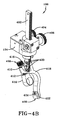
図3A及び図3Bは、第1の取付システム105の前面図及び斜視図をそれぞれ示す。第1の取付システム105は、レール302と、つまみ304と、つまみ306とを含む高さ調整装置130を含む。高さ調整装置130は垂直方向(例えば、ワークピース及び溶接領域Zの方又はワークピース及び溶接領域Zから遠ざかる方)の移動にレール302を用いる。レール302は複数の歯を含むことができる。複数の歯にはラックアンドピニオン式にギアが係合しており(図示していないが図7で解説)、ギアを回転させて動作をできるようにする。図示のラックアンドピニオンシステムと同じ効果を得るのに他の線形アクチュエータを使用してもよいと考えられる。
3A and 3B show a front view and a perspective view of the
つまみ306によってギアの回転を容易にできる。つまみ306への言及は、ギアを回すか又は回転させて複数の歯の周りでギアを動かす任意の好適な機構(例えば、とりわけクランク、スクリュー、レバー、電子装置)を含むことが分かる。高さ調整装置130は、第1の取付システム105の動きを調整できるように構成されたつまみ304をさらに含む。例えば、つまみ304を回すことで、第1の取付システム105を前方又は後方に(例えば、図2を参照して、前方向は左側であり、後ろ方向は右側である)操作できる。つまみ304は、回されるか又は回転されることで動いた方向に基づき第1の取付システムを前方に又は後方に動かす任意の好適な機構(例えば、とりわけクランク、スクリュー、レバー、電子装置)であってもよいことが分かる。
The
レール302は上端と、該上端と反対側の下端とを含み、下端は、1つ以上の固定具によりブラケット318を連結させる開口320を含むことができる。一実施形態では、開口320は、ブラケット318を水平方向(例えば、溶接領域Zに関連して左右方向)及び/又は垂直方向(例えば、溶接領域Zに関連して上下方向)にさらに調整できるようにする。例えば、ブラケット318は上部開口、中央開口及び下部開口を含むことができ、上部開口及び下部開口はブラケット318の水平調整及び/又は垂直調整を可能にする。特定の実施形態では、上部開口及び下部開口は、ブラケット318を水平方向及び/又は垂直方向に調整し、固定具で所望の位置に固定できるようにするためにカプセル形状(capsule shaped)であってもよい。
The
ブラケット318は第1のアーム部308及び第2のアーム部309を含み、第1のアーム部308は、上部と該上部と反対側の下部とを含み、下部はカメラ装置取付部314を含む。カメラ装置取付部314はカメラ装置(例えば、カメラ装置113)を支持する。第1のアーム部308は第1の面にあるのに対して、第2のアーム部309は第2の面604にある(第1の面及び第2の面の解説については図5参照)。第1の面602と第2の面604とは距離D離れている(距離Dの解説については図5参照)。第2のアーム部309はオフセット部613(図5で解説)をさらに含む。オフセット部613は、第1の面から距離D離れた第2の面604にあり、カメラ装置113の一部を受容する凹部615を規定する。第2のアーム部309は、第1の面602でワイヤガイド104’を支持してワイヤガイド104’を溶接領域Z上の位置に向けるワイヤガイド取付部322を含む。ワイヤガイド104’は、開口324と連結するか又は開口324を通って連結する固定具によりワイヤガイド取付部322に固定できる。
The
一実施形態では、第2のアーム部309は、上部からオフセット部613に遷移する(図5で解説)第1の遷移領域610(図5で解説)と、オフセット部613からワイヤガイド取付部322に遷移する第2の遷移領域604(図5で説明)とを含む。例えば、第1の遷移領域610又は第2の遷移領域612のうちの少なくとも一方は、限定されないが湾曲部材、非湾曲部材、連続湾曲、傾斜部材、その組み合わせであり得る。
In one embodiment, the
一実施形態では、第1のアーム部308は、上部と該上部の反対側の下部とを含む蝶ネジ316を含む。下部はネジ山部310を含む。ネジ山部310はブラケット318の開口及びバルブ(図示していないが図7で解説)の上部の開口に挿入でき、バルブはボール及びネジ山付ネック部(ball and threaded neck)312を含む。ネジ山付ネック部312はカメラ装置取付部314に連結され、ネジ山付ネック部312は第1のアーム部308の位置の調整を提供する。蝶ネジ316及びバルブは、第1のアーム部308、ひいてはカメラ装置取付部314及び/又はカメラ装置113を360°動かすことができるようにするボールジョイントを提供する。
In one embodiment, the
図3Aに示す第1の取付システム105の背面図は、図4Aに示す第2の取付システム106の前面図と実質的に同様であり得ることが分かる。例えば、ブラケット318、レール302及び/又は高さ調整装置130のうちの少なくとも1つの背面図は、図4Aに示すブラケット418、レール402及び/又は高さ調整装置124と実質的に同様であり得る。それに加えて、図3Bに示す第1の取付システム105の背面斜視図は、図4Bに示す第2の取付システム106の前面斜視図と実質的に同様であり得る。例えば、ブラケット318、レール302及び/又は高さ調整装置130のうちの少なくとも1つの背面図は、図4Aに示すブラケット418、レール402及び/又は高さ調整装置124と実質的に同様であり得る。
It will be appreciated that the rear view of the
図4A及び図4Bは、第2の取付システム106の前面図及び斜視図をそれぞれ示す。第2の取付システム106は、レール402と、つまみ404と、つまみ406とを含む高さ調整装置124を含む。高さ調整装置124は垂直方向(例えば、ワークピース及び溶接領域Zの方又はワークピース及び溶接領域Zから遠ざかる方)の移動にレール402を用いる。レール402は複数の歯を含むことができ、複数の歯に対してギア(図示していないが図7で解説)を回転させて動作できるようにする。つまみ406によってギアを動かすことができる。しかしながら、つまみ406は、ギアを回すか又は回転させて複数の歯の周りでギアを動かす任意の好適な機構(例えば、とりわけクランク、スクリュー、レバー、電子装置)であってもよいことが分かる。高さ調整装置124は、第2の取付システム106の動きを調整できるように構成されたつまみ404をさらに含む。例えば、つまみ404を回すことで、第2の取付システム106を前方又は後方に(例えば、図2を参照して、前方向は左側であり、後ろ方向は右側である)操作できる。つまみ404は、回されるか又は回転されることで動いた方向に基づき第2の取付システムを前方に又は後方に動かす任意の好適な機構(例えば、とりわけクランク、スクリュー、レバー、電子装置)であってもよいことが分かる。
4A and 4B show a front view and a perspective view of the
レール402は、上端と該上端の反対側の下端とを含み、下端は、1つ以上の固定具によりブラケット418を連結させる開口420を含むことができる。一実施形態では、開口420は、ブラケット418を水平方向(例えば、溶接領域Zに関連して左右方向)及び/又は垂直方向(例えば、溶接領域Zに関連して上下方向)にさらに調整できるようにする。例えば、ブラケット418は上部開口、中央開口及び下部開口を含むことができ、上部開口及び下部開口はブラケット418の水平調整及び/又は垂直調整を可能にする。特定の実施形態では、上部開口及び下部開口は、ブラケット418を水平方向及び/又は垂直方向に調整し、固定具で所望の位置に固定できるようにするためにカプセル形状であってもよい。
The
ブラケット418は第1のアーム部408及び第2のアーム部409を含み、第1のアーム部408は、上部と該上部の反対側の下部とを含み、下部はカメラ装置取付部414を含む。カメラ装置取付部414はカメラ装置(例えば、カメラ装置112)を支持する。第1のアーム部408は第1の面にあるのに対して、第2のアーム部409は第2の面にある(第1の面及び第2の面の解説については図6参照)。第1の面と第2の面とは距離D離れている(距離Dの解説については図5参照)。第2のアーム部409はオフセット部(図6で解説)をさらに含む。オフセット部は、第1の面から距離D離れた第2の面にあり、カメラ装置112の一部を受容する凹部を規定する。第2のアーム部409は、第1の面にワイヤガイド104を支持してワイヤガイド104を溶接領域Z上の位置に向けるワイヤガイド取付部422を含む。ワイヤガイド104は、開口424と連結するか又は開口424を通って連結する固定具によりワイヤガイド取付部422に固定できる。
The
一実施形態では、第2のアーム部409は、上部からオフセット部に遷移する(図6で解説)第1の遷移領域(図6で解説)と、オフセット部からワイヤガイド取付部に遷移する第2の遷移領域(図6で説明)を含む。例えば、第1の遷移領域又は第2の遷移領域のうちの少なくとも一方は、限定されないが湾曲部材、非湾曲部材、連続湾曲部材、傾斜部材、その組み合わせであり得る。
In one embodiment, the
一実施形態では、第1のアーム部408は、上部と該上部の反対側の下部とを含む蝶ネジ416を含む。下部はネジ山部410を含む。ネジ山部410はブラケット418の開口及びバルブ(図示していないが図7で解説)の上部の開口に挿入でき、バルブはボール及びネジ山付ネック部412を含む。ネジ山付ネック部412はカメラ装置取付部414に連結され、ネジ山付ネック部412は第1のアーム部408の位置の調整を提供する。蝶ネジ416及びバルブは、第1のアーム部408、ひいてはカメラ装置取付部414及び/又はカメラ装置112を360°動かすことができるようにするボールジョイントを提供する。
In one embodiment, the
図4Aに示す第2の取付システム106の背面図は、図3Aに示す第1の取付システム105の前面図と実質的に同様であり得ることが分かる。例えば、ブラケット418、レール402及び/又は高さ調整装置124のうちの少なくとも1つの背面図は、図3Aに示すブラケット318、レール302及び/又は高さ調整装置130と実質的に同様であり得る。それに加えて、図4Bに示す第2の取付システム106の背面斜視図は、図3Bに示す第1の取付システム105の前面斜視図と実質的に同様であり得る。例えば、ブラケット418、レール402及び/又は高さ調整装置124のうちの少なくとも1つの背面図は、図3Aに示すブラケット318、レール302及び/又は高さ調整装置130と実質的に同様であり得る。
It will be appreciated that the rear view of the
図5は、円周溶接システム100のためにカメラ装置112及びワイヤガイド104を支持する第2の取付システム106の側面図を示す。前で解説したように、取付システム(例えば、第1の取付システム105、第2の取付システム106)の第1のアーム部(例えば、第1のアーム部308、第1のアーム部408)は、第2の面604から距離D離れた第1の面602にあり得る。第2のアーム部(例えば、第2のアーム部309、第2のアーム部409)は、第1の面602から距離D離れた第2の面604にあり、カメラ装置(例えば、カメラ装置113、112)の少なくとも一部を受容する凹部615を規定するオフセット部613を含み得る。一実施形態では、第1のアーム部(例えば、第1のアーム部308、第1のアーム部408)は、カメラ装置を受容するために開口を有するカメラ装置取付部(例えば、カメラ装置取付部314、カメラ装置取付部414)を含む。さらに、第1の遷移領域610(例えば、図3A、図3B、図4A及び図4Bで解説)を第2のアーム部に図示している。それに加えて、第2の遷移領域612(例えば、図3A、図3B、図4A及び図4Bで解説)を第2のアーム部に図示している。この特定の例では、第1の遷移領域610及び第2の遷移領域612を湾曲部材として図示しているが、第1の遷移領域610又は第2の遷移領域612のいずれかは、とりわけ湾曲部材、非湾曲部材、傾斜部材、連続湾曲部材のうちの少なくとも1つであり得る。
FIG. 5 shows a side view of the
例えば、カメラ装置取付部はカメラ装置の一部を受容する開口を含むことができ、開口は中心点606を含むことができる。ワイヤガイド取付部(例えば、ワイヤガイド取付部322、422)はワイヤガイド(例えば、ワイヤガイド140’、140)の一部を受容する開口を含むことができ、開口は中心点608を含むことができる。本願に係るイノベーションの一態様によれば、中心点606は中心点608と同一面にある。特定の例では、中心点606及び中心点608は第1の面602にある。図6は第2の取付システム106の側面図を示すが、その第1の面602、第2の面604、距離D、中心点606及び/又は中心点608は第1の取付システム105に対応可能であり、第2の取付システム106に限定されない。
For example, the camera device mount can include an opening that receives a portion of the camera device, and the opening can include a
図6は、円周溶接システム100のためにカメラ装置及びワイヤガイドを支持する取付システム(例えば、第1の取付システム105、第2の取付システム106)の分解図を示す。第2の取付システム106の分解図及び任意の部分、要素及び/又は特徴は第1の取付システム105に対応可能であり、第2の取付システム106に限定されないことが分かる。第2の取付システム106は、第1のアーム部408及び第2のアーム部409を含むブラケット418を含む。第1のアーム部はネジ山部410を有する蝶ネジ416と、バルブ412と、カメラ装置取付部414とを含む。第2の取付システム106は、ギア718、円筒720、つまみ406、つまみ404、固定具716、固定具712、プレート728、部材722、固定具724、固定具726、調整スクリュー又は固定具730、固定具710、レール402を受容する部材731、固定具717、円筒714、ワッシャー734、ワッシャー又はワッシャーの一部732、部材706、ワッシャー708、プレート704及び/又は固定具702を含む高さ調整装置124をさらに含む。
FIG. 6 shows an exploded view of a mounting system (eg, first mounting
一実施形態では、溶接機システムが提供され、第1のアーム部はバルブに連結される蝶ネジをさらに含み、バルブは下部にネック部を含み、上部にボールを含む。一実施形態では、蝶ネジ及びバルブはカメラ装置の焦点位置を調整し、蝶ネジを締めることでバルブ及びカメラ装置の位置が安定する。一実施形態では、第2のアーム部は上部と、該上部の反対側の下部とをさらに含み、下部はワイヤガイド取付部を含む。一実施形態では、第2のアーム部は、上部からオフセット部に遷移する第1の遷移領域と、オフセット部からワイヤガイド取付部に遷移する第2の遷移領域とをさらに含む。一実施形態では、第1の遷移領域及び第2の遷移領域は湾曲部材である。一実施形態では、カメラ装置の少なくとも一部は円筒状である。一実施形態では、第1の遷移領域及び第2の遷移領域は連続湾曲である。一実施形態では、第1の遷移領域又は第2の遷移領域のうちの少なくとも一方は非湾曲部材である。 In one embodiment, a welder system is provided, wherein the first arm portion further includes a thumbscrew coupled to the valve, the valve including a neck portion at the bottom and a ball at the top. In one embodiment, the thumbscrew and valve adjust the focal position of the camera device, and tightening the thumbscrew stabilizes the position of the valve and camera device. In one embodiment, the second arm portion further includes an upper portion and a lower portion opposite to the upper portion, and the lower portion includes a wire guide attachment portion. In one embodiment, the second arm portion further includes a first transition region that transitions from the upper portion to the offset portion, and a second transition region that transitions from the offset portion to the wire guide attachment portion. In one embodiment, the first transition region and the second transition region are curved members. In one embodiment, at least a portion of the camera device is cylindrical. In one embodiment, the first transition region and the second transition region are continuous curves. In one embodiment, at least one of the first transition region or the second transition region is a non-curved member.
一実施形態では、溶接機システムは、ブラケットをシャーシに取り付ける支持部材を含む。一実施形態では、溶接機システムは、複数の歯に嵌合するギアを備えたレールを有する高さ調整装置を含み、レールはブラケットに連結する端部を含む。溶接機システムのそのような実施形態では、高さ調整装置及びブラケットはギアに基づいて移動し、該移動は溶接領域の方又は溶接領域から離れる方のうちの少なくとも一方である。一実施形態では、高さ調整装置はシャーシに連結されている。一実施形態では、溶接機システムは、ブラケットを高さ調整装置に取り付け、高さ調整装置をシャーシに取り付ける支持部材を含む。一実施形態では、溶接機システムは、ブラケットをレールに連結しつつ、水平面におけるブラケットの調整を提供する少なくとも1つの固定具を含む。 In one embodiment, the welder system includes a support member that attaches the bracket to the chassis. In one embodiment, the welder system includes a height adjustment device having a rail with a gear that fits a plurality of teeth, the rail including an end that connects to a bracket. In such an embodiment of the welder system, the height adjustment device and the bracket move based on the gear, the movement being at least one of the weld area or the distance away from the weld area. In one embodiment, the height adjustment device is coupled to the chassis. In one embodiment, the welder system includes a support member that attaches the bracket to the height adjuster and attaches the height adjuster to the chassis. In one embodiment, the welder system includes at least one fixture that provides adjustment of the bracket in a horizontal plane while coupling the bracket to the rail.
一実施形態では、ブラケットが提供され、当該ブラケットは、ギア及び複数の歯を用いてブラケットの高さを調整する高さ調整装置を含む。一実施形態では、ブラケットは、上部と該上部の反対側の下部とをさらに含む第2のアーム部を含む。本実施形態では、ブラケットは、上部からオフセット部に遷移する第1の遷移部と、オフセット部からワイヤガイド取付部又は下部のうちの少なくとも一方に遷移する第2の遷移部とを含む。 In one embodiment, a bracket is provided that includes a height adjustment device that uses a gear and a plurality of teeth to adjust the height of the bracket. In one embodiment, the bracket includes a second arm portion that further includes an upper portion and a lower portion opposite the upper portion. In the present embodiment, the bracket includes a first transition portion that transitions from the upper portion to the offset portion, and a second transition portion that transitions from the offset portion to at least one of the wire guide attachment portion and the lower portion.
一実施形態では、ブラケットは第1の遷移部及び第2の遷移部を含み、第1の遷移部又は第2の遷移部のうちの少なくとも一方は湾曲部材である。一実施形態では、第1の遷移部又は第2の遷移部のうちの少なくとも一方は非湾曲部材である。一実施形態では、ブラケットは、溶接領域上の位置にカメラ装置を向けるために第1のアーム部を360°調整できるようにするボールジョイントを有する第1のアーム部を含む。ブラケットの一実施形態では、第1のアーム部又は第2のアーム部のうちの少なくとも一方は、銅、アルミニウム、銅の合金、ベリリウム銅、タングステン銅、導電性金属、スチール又はセラミックからなる群から選択される材料で構成されている。 In one embodiment, the bracket includes a first transition portion and a second transition portion, and at least one of the first transition portion or the second transition portion is a curved member. In one embodiment, at least one of the first transition portion or the second transition portion is a non-curved member. In one embodiment, the bracket includes a first arm portion having a ball joint that allows the first arm portion to be adjusted 360 ° to direct the camera device to a position on the weld area. In one embodiment of the bracket, at least one of the first arm portion or the second arm portion is from the group consisting of copper, aluminum, copper alloy, beryllium copper, tungsten copper, conductive metal, steel or ceramic. Consists of selected materials.
上記の例は、本考案の様々な態様のいくつかの可能性のある実施形態を説明するためのものに過ぎず、当業者であれば本明細書及び添付の図面を読み、理解した際に同等の変更及び/又は修正を思い付く。特に、上述のコンポーネント(アセンブリ、装置、システム、回路等)によって行われる様々な機能に関して、そのようなコンポーネントを説明するのに用いた用語(「手段」への言及も含む)は、別段指摘がない限り、本考案の説明した実施において機能を行う開示の構造とは構造的に同等ではなくても、説明したコンポーネントの特定の機能を行う(例えば、機能的に同等な)ハードウェア、ソフトウェア又はその組み合わせ等の任意のコンポーネントに対応する。それに加え、いくつかの実施のうちの1つだけに関連して本考案の特定の特徴を開示してきたが、そのような特徴を他の実施の1つ以上の他の特徴と組み合わせることは、所定の又は特定の用途にとって望ましく、有利であり得るため組み合わせてもよい。また、詳細な説明及び/又は請求項では「含む(including、includes)」、「有する(having、has)」、「備える(with)」又はその異形を用いているが、それらの用語は「包含する(comprising)」と同様に包含的であることを意図している。 The above examples are merely illustrative of some possible embodiments of the various aspects of the present invention, and those of ordinary skill in the art will understand upon reading and understanding this specification and the accompanying drawings. Come up with equivalent changes and / or modifications. In particular, with respect to the various functions performed by the components described above (assemblies, devices, systems, circuits, etc.), the terms used to describe such components (including references to “means”) are specifically pointed out. Unless otherwise indicated, the hardware, software, or software that performs a particular function (eg, functionally equivalent) of the described component, even though it is not structurally equivalent to the disclosed structure that performs the function in the described implementation of the invention It corresponds to any component such as the combination. In addition, while certain features of the invention have been disclosed in connection with only one of several implementations, combining such features with one or more other features of other implementations They may be combined as they may be desirable and advantageous for a given or specific application. Also, the detailed description and / or claims use the terms “including”, “having”, “with”, or variants thereof, but these terms are “including” It is intended to be inclusive as well as “comprising”.
本説明では、本考案を開示し、当業者が本考案(任意の装置又はシステムの製造及び使用並びに内在される方法を行うことを含む)を実施できるようにするために、最良の形態を含めた例を用いている。本考案の範囲は請求項によって規定され、当業者が思い付き得る他の例も含み得る。そのような他の例は、それらが請求項に文字通り記載されたものと差異がない構造的要素を有するか又は請求項に文字通り記載されたものとの差異がごくわずかな同等の構造的要素を含む場合、それらは請求項の範囲に含まれる。 This description discloses the invention and includes the best mode to enable those skilled in the art to practice the invention (including making and using any device or system and performing inherent methods). An example is used. The scope of the invention is defined by the claims, and may include other examples that occur to those skilled in the art. Such other examples may have structural elements that are not different from those literally stated in the claims, or equivalent structural elements that are only slightly different from those literally stated in the claims. If included, they are within the scope of the claims.
本願の出願時に出願人が知っていた本考案を実施するための最良の形態を説明する目的で、最良の形態を説明してきた。実施例は例示に過ぎず、本考案を限定することを意図したものではない。本考案は請求項の範囲及び精神により判断される。好ましい実施形態及び代替的実施形態を参照しながら本考案を説明してきた。当業者であれば本明細書を読んで理解した際に変更及び修正に気付くのは明らかである。そのような変更及び修正は、それらが添付の請求項又はその同等物の範囲に含まれる限り本願に含まれる。 The best mode has been described for the purpose of describing the best mode for carrying out the invention which the applicant knew at the time of filing of the present application. The examples are illustrative only and are not intended to limit the invention. The invention is determined by the scope and spirit of the claims. The invention has been described with reference to preferred and alternative embodiments. Obviously, changes and modifications will become apparent to those skilled in the art upon reading and understanding this specification. Such changes and modifications are included in this application as long as they fall within the scope of the appended claims or their equivalents.
30 溶接トーチ
32 電極
100 溶接機システム
101 溶接機本体又はシャーシ
103 溶接ワイヤ源又はスプール
104 ワイヤガイド
104’ ワイヤガイド
105 第1の取付システム
106 第2の取付システム又はブラケット
107 調整器又はコントローラ
108 ガス源
112 カメラ装置
113 カメラ装置
124 高さ調整装置
126 支持部材
130 高さ調整装置
132 支持部材
302 レール
304 つまみ
306 つまみ
308 第1のアーム部
309 第2のアーム部
310 ネジ山部
312 ネジ山付ネック部
314 カメラ装置取付部
316 蝶ネジ
318 ブラケット
320 開口
322 ワイヤガイド取付部
324 開口
402 レール
404 つまみ
406 つまみ
408 第1のアーム部
409 第2のアーム部
410 ネジ山部
412 ネジ山付ネック部
414 装置取付部
416 蝶ネジ
418 ブラケット
420 開口
422 ワイヤガイド取付部
424 開口
602 第1の面
603 第2の面
606 中心点
608 中心点
610 第1の遷移部
612 第2の遷移領域
613 オフセット部
615 凹部
702 固定具
704 面
706 部材
708 ワッシャー
710 固定具
712 固定具
713 部材
714 円筒
716 固定具
717 固定具
718 ギア
720 円筒
722 部材
724 固定具
728 面
730 調整スクリュー又は固定具
732 ワッシャー又はワッシャーの一部
734 ワッシャー
D 距離
G 開先
P パイプ
S シールドガス
W ワイヤ
Z 溶接領域
30
Claims (15)
シャーシを有し、ワークピースの近傍に支持される円周溶接機と、
前記シャーシに連結され、前記ワークピース上に溶接継手を形成するように適合された電極を含む溶接トーチと、
溶接ワイヤ源に接続され、ワイヤガイドに、そして前記電極が前記ワークピース上に溶接材を溶着する溶接領域に溶接ワイヤを提供するワイヤ送給装置と、
前記シャーシに連結されたブラケットであって、
第1の面にある第1のアーム部であって、該第1のアーム部の一部はカメラ装置の焦点を前記溶接領域に合わせるように適合されている、第1のアーム部と、
第2のアーム部であって、該第2のアーム部は、前記第1の面から距離D離れた第2の面にあり、前記カメラ装置の少なくとも一部を受容する凹部を規定するオフセット部を有し、該第2のアーム部は、前記溶接ワイヤを前記溶接領域に提供するために前記ワイヤガイドを前記第1の面に支持するワイヤガイド取付部を含む、第2のアーム部と、
を含む、ブラケットと、
を含む溶接機システム。 A welding machine system,
A circumferential welder having a chassis and supported in the vicinity of the workpiece;
A welding torch coupled to the chassis and including an electrode adapted to form a weld joint on the workpiece;
A wire feeder that is connected to a welding wire source and provides a welding wire to a wire guide and to a welding region in which the electrode deposits a weld on the workpiece;
A bracket connected to the chassis,
A first arm portion on a first surface, wherein a portion of the first arm portion is adapted to focus a camera device on the welding area;
An offset portion that is a second arm portion, the second arm portion being on a second surface at a distance D from the first surface, and defining a recess that receives at least a part of the camera device. The second arm portion includes a wire guide attachment portion that supports the wire guide on the first surface to provide the welding wire to the welding region; and
Including brackets, and
Including welding machine system.
前記蝶ネジ及び前記バルブは前記カメラ装置の焦点位置を調整し、前記蝶ネジを締めると前記バルブ及び前記カメラ装置の位置が安定する、請求項1に記載の溶接機システム。 The first arm portion further includes a thumbscrew connected to a valve, the valve including a neck portion at a lower portion and a ball at an upper portion;
The welder system according to claim 1, wherein the thumb screw and the valve adjust a focal position of the camera device, and the position of the valve and the camera device is stabilized when the thumb screw is tightened.
前記レールは前記ブラケットに連結する端部を含み、
前記高さ調整装置及び前記ブラケットは前記ギアに基づいて動き、該動きは前記溶接領域の方又は前記溶接領域から遠ざかる方の少なくとも一方であり、
前記高さ調整装置は前記シャーシに連結されている、請求項1乃至6のいずれか一項に記載の溶接機システム。 Further comprising a height adjustment device having a rail with a gear that fits a plurality of teeth;
The rail includes an end connected to the bracket;
The height adjustment device and the bracket move based on the gear, the movement being at least one of the welding area or the distance away from the welding area;
The welder system according to any one of claims 1 to 6, wherein the height adjusting device is coupled to the chassis.
第1の面にあり、上部と該上部の反対側の下部とを含む第1のアーム部であって、該下部はカメラ装置の第1の部分を受容するカメラ装置取付部を含み、該カメラ装置は溶接領域に焦点が合うように配置される、第1のアーム部と、
第2のアーム部であって、前記第1の面から距離D離れた第2の面にあり、前記カメラ装置の第2の部分を受容する凹部を規定するオフセット部を有し、該第2のアーム部は、前記溶接領域に溶接ワイヤの一部を提供するためにワイヤガイドを前記第1の面に支持するワイヤガイド取付部を含み、前記カメラ装置取付部の中心点は前記ワイヤガイド取付部の中心点と同じ面にある、第2のアーム部と、
を含むブラケット。 A bracket for attaching a camera device to a welding machine system,
A first arm portion on a first surface and including an upper portion and a lower portion opposite to the upper portion, the lower portion including a camera device mounting portion for receiving a first portion of the camera device; The apparatus is arranged to focus on the weld area, the first arm part;
A second arm portion on a second surface at a distance D from the first surface, and having an offset portion for defining a recess for receiving a second portion of the camera device; The arm portion includes a wire guide mounting portion that supports a wire guide on the first surface to provide a part of the welding wire to the welding region, and a center point of the camera device mounting portion is the wire guide mounting portion. A second arm portion in the same plane as the center point of the portion;
Including bracket.
上部及び該上部の反対側の下部と、
該上部から前記オフセット部に遷移する第1の遷移部と、
前記オフセット部から前記ワイヤガイド取付部又は該下部のうちの少なくとも一方に遷移する第2の遷移部と、
をさらに含み、
前記第1の遷移部又は前記第2の遷移部のうちの少なくとも一方は湾曲部材であるか又は非湾曲部材である、請求項10又は11に記載のブラケット。 The second arm portion is
An upper part and a lower part opposite to the upper part;
A first transition part transitioning from the upper part to the offset part;
A second transition portion that transitions from the offset portion to at least one of the wire guide attachment portion or the lower portion;
Further including
The bracket according to claim 10 or 11, wherein at least one of the first transition portion or the second transition portion is a curved member or a non-curved member.
シャーシを有し、ワークピースの近傍に支持される円周溶接機と、
前記シャーシに連結され、前記ワークピース上に溶接継手を形成するように適合された電極を含む溶接トーチと、
溶接ワイヤ源に接続され、前記電極が前記ワークピース上に溶接材を溶着する溶接領域に溶接ワイヤを向かわせるように構成されたワイヤガイドに溶接ワイヤを提供するワイヤ送給装置と、
前記シャーシに連結されたブラケットであって、
第1の面にある第1のアーム部であって、該第1のアーム部の一部はカメラ装置の焦点を前記溶接領域に合わせるように適合されている、第1のアーム部と、
第2のアーム部であって、該第2のアーム部は、前記第1の面から距離D離れた第2の面にあり、前記カメラ装置の少なくとも一部を受容する凹部を規定するオフセット部を有し、該第2のアーム部は、溶接ワイヤの一部を前記溶接領域に提供するために前記ワイヤガイドを前記第1の面に支持するワイヤガイド取付部を含む、第2のアーム部と、
を含む、ブラケットと、
を含み、
前記第2のアーム部は、
上部及び該上部の反対側の下部と、
該上部から前記オフセット部に遷移する第1の遷移部と、
前記オフセット部から前記ワイヤガイド取付部又は該下部のうちの少なくとも一方に遷移する第2の遷移部と、
をさらに含み、
前記第1の遷移部、前記オフセット部及び前記第2の遷移部は連続湾曲を形成する、円周溶接システム。 A circumferential welding system,
A circumferential welder having a chassis and supported in the vicinity of the workpiece;
A welding torch coupled to the chassis and including an electrode adapted to form a weld joint on the workpiece;
A wire feeder for providing a welding wire to a wire guide connected to a welding wire source and configured to direct the welding wire to a welding region in which the electrode deposits a welding material on the workpiece;
A bracket connected to the chassis,
A first arm portion on a first surface, wherein a portion of the first arm portion is adapted to focus a camera device on the welding area;
An offset portion that is a second arm portion, the second arm portion being on a second surface at a distance D from the first surface, and defining a recess that receives at least a part of the camera device. And the second arm portion includes a wire guide mounting portion that supports the wire guide on the first surface to provide a portion of the welding wire to the welding region. When,
Including brackets, and
Including
The second arm portion is
An upper part and a lower part opposite to the upper part;
A first transition part transitioning from the upper part to the offset part;
A second transition portion that transitions from the offset portion to at least one of the wire guide attachment portion or the lower portion;
Further including
The circumferential welding system, wherein the first transition portion, the offset portion, and the second transition portion form a continuous curve.
Applications Claiming Priority (3)
| Application Number | Priority Date | Filing Date | Title |
|---|---|---|---|
| US13/830,945 US9527153B2 (en) | 2013-03-14 | 2013-03-14 | Camera and wire feed solution for orbital welder system |
| US13/830,945 | 2013-03-14 | ||
| PCT/IB2014/000300 WO2014140730A2 (en) | 2013-03-14 | 2014-03-12 | Camera and wire feed solution for orbital welder system |
Publications (1)
| Publication Number | Publication Date |
|---|---|
| JP3203667U true JP3203667U (en) | 2016-04-14 |
Family
ID=50628857
Family Applications (1)
| Application Number | Title | Priority Date | Filing Date |
|---|---|---|---|
| JP2015600142U Expired - Fee Related JP3203667U (en) | 2013-03-14 | 2014-03-12 | Camera and wire feeding solutions for circumferential welder systems |
Country Status (5)
| Country | Link |
|---|---|
| US (1) | US9527153B2 (en) |
| JP (1) | JP3203667U (en) |
| CN (1) | CN105189008B (en) |
| DE (1) | DE212014000075U1 (en) |
| WO (1) | WO2014140730A2 (en) |
Families Citing this family (17)
| Publication number | Priority date | Publication date | Assignee | Title |
|---|---|---|---|---|
| CN104733947B (en) * | 2013-12-23 | 2017-02-15 | 珠海格力电器股份有限公司 | Coiling device and household appliance with same |
| US20160193681A1 (en) * | 2015-01-07 | 2016-07-07 | Illinois Tool Works Inc. | Synchronized image capture for welding machine vision |
| US10773329B2 (en) | 2015-01-20 | 2020-09-15 | Illinois Tool Works Inc. | Multiple input welding vision system |
| CN113192374B (en) | 2015-03-06 | 2023-09-01 | 伊利诺斯工具制品有限公司 | Sensor assisted head mounted display for welding |
| CN107980153B (en) | 2015-03-09 | 2021-10-22 | 伊利诺斯工具制品有限公司 | Method and apparatus for providing visual information associated with a welding operation |
| US9977242B2 (en) | 2015-03-26 | 2018-05-22 | Illinois Tool Works Inc. | Control of mediated reality welding system based on lighting conditions |
| US10363632B2 (en) | 2015-06-24 | 2019-07-30 | Illinois Tool Works Inc. | Time of flight camera for welding machine vision |
| PL234452B1 (en) * | 2017-11-30 | 2020-02-28 | Zisco Spolka Z Ograniczona Odpowiedzialnoscia Spolka Komandytowa | Method for orbital welding and the device for orbital welding |
| CN108544060B (en) * | 2018-07-12 | 2020-10-27 | 华南理工大学 | Multifunctional pipe-pipe all-position automatic TIG welding head structure |
| US11741802B2 (en) * | 2018-12-27 | 2023-08-29 | John Otis Farneman | Home security light bulb adapter |
| US10909823B2 (en) * | 2018-12-27 | 2021-02-02 | Heidi Bear Enterprises, Llc | Home security light bulb adapter |
| US11450233B2 (en) | 2019-02-19 | 2022-09-20 | Illinois Tool Works Inc. | Systems for simulating joining operations using mobile devices |
| US11521512B2 (en) | 2019-02-19 | 2022-12-06 | Illinois Tool Works Inc. | Systems for simulating joining operations using mobile devices |
| MX2022005434A (en) * | 2019-11-05 | 2022-06-16 | Schunk Sonosystems Gmbh | Ultrasonic welding device with integrated camera assembly. |
| US11721231B2 (en) | 2019-11-25 | 2023-08-08 | Illinois Tool Works Inc. | Weld training simulations using mobile devices, modular workpieces, and simulated welding equipment |
| US11322037B2 (en) | 2019-11-25 | 2022-05-03 | Illinois Tool Works Inc. | Weld training simulations using mobile devices, modular workpieces, and simulated welding equipment |
| CN114043044B (en) * | 2021-11-04 | 2023-03-14 | 吴钩科技(苏州)有限公司 | Wire feeding angle and position remote control adjusting mechanism in automatic TIG pipeline welding machine |
Family Cites Families (157)
| Publication number | Priority date | Publication date | Assignee | Title |
|---|---|---|---|---|
| US2138837A (en) | 1938-12-06 | Electromagnetic friction device | ||
| US1114793A (en) | 1914-01-19 | 1914-10-27 | Cincinnati Gear Cutting Machine Company | Controlling mechanism. |
| US1704846A (en) | 1923-09-01 | 1929-03-12 | Smith Corp A O | Method of and apparatus for electrically welding pipe couplings in alpha continuous operation |
| US2515302A (en) | 1947-08-27 | 1950-07-18 | Air Reduction | Apparatus for controlling relative movement between a gas torch and a workpiece |
| US2547872A (en) | 1948-01-31 | 1951-04-03 | Stacey Brothers Gas Constructi | Welding torch |
| US2710328A (en) | 1952-07-31 | 1955-06-07 | Beckman Instruments Inc | Welding process |
| DE965794C (en) | 1953-12-14 | 1957-06-19 | Union Carbide & Carbon Corp | Process and device for inert gas arc welding with non-melting electrode and automatic welding wire feed |
| US2795689A (en) | 1954-02-24 | 1957-06-11 | Louis C Mcnutt | Automatic pipe welding apparatus |
| US2806125A (en) | 1954-10-29 | 1957-09-10 | Westinghouse Electric Corp | Welding gun |
| US2845524A (en) | 1955-11-30 | 1958-07-29 | Westinghouse Electric Corp | Arc welding apparatus |
| GB848941A (en) | 1957-12-20 | 1960-09-21 | British Oxygen Co Ltd | Spool holder |
| US3048691A (en) | 1960-03-31 | 1962-08-07 | Westinghouse Electric Corp | Welding gun |
| US3179781A (en) | 1961-04-18 | 1965-04-20 | Union Carbide Canada Ltd | Pipe welding machine and process |
| US3137782A (en) | 1962-10-23 | 1964-06-16 | Exxon Research Engineering Co | Process for welding thick materials |
| US3207881A (en) | 1963-03-19 | 1965-09-21 | American Mach & Foundry | Arc welding apparatus and method |
| US3235705A (en) | 1963-07-19 | 1966-02-15 | Air Reduction | Vertical welding |
| US3239648A (en) | 1963-10-01 | 1966-03-08 | Harnischfeger Corp | Apparatus for arc welding |
| GB1142854A (en) | 1965-05-11 | 1969-02-12 | Clarke Chapman Ltd | Improvements relating to orbital welding apparatus |
| US3427428A (en) | 1965-09-14 | 1969-02-11 | Exxon Research Engineering Co | Apparatus and method for welding metal pipes and the like |
| US3542996A (en) | 1966-04-18 | 1970-11-24 | Smith Corp A O | Automatic control system for angular and planar electrode orientation |
| US3323752A (en) | 1966-04-27 | 1967-06-06 | Sperry Rand Corp | Welding wire spool stand |
| US3576966A (en) | 1967-03-27 | 1971-05-04 | Air Reduction | Arc-welding in narrow gap |
| US3567900A (en) | 1968-08-14 | 1971-03-02 | Battelle Development Corp | Welding method and apparatus |
| GB1272568A (en) | 1968-10-07 | 1972-05-03 | Foster Wheeler Brown Boilers | Improvements in welding torches and heads thereof |
| US3602687A (en) | 1969-06-23 | 1971-08-31 | Battelle Development Corp | Arc length control |
| US3604039A (en) | 1969-09-24 | 1971-09-14 | Aeroglide Corp | Cleaning means for guide bushings |
| FR2138564B1 (en) | 1971-05-21 | 1973-05-25 | Paulange Serge | |
| US3718798A (en) | 1971-06-21 | 1973-02-27 | Crc Crose Int Inc | Traveling welding apparatus |
| US3806694A (en) | 1972-05-17 | 1974-04-23 | Crc Crose Int Inc | Apparatus and method for welding joints between metal shapes |
| US3815807A (en) | 1972-08-18 | 1974-06-11 | Zeta Int Eng Inc | Automatic welding apparatus |
| US3806691A (en) | 1972-11-20 | 1974-04-23 | Cammann Mfg Co | Tool positioner |
| US3826888A (en) | 1973-03-05 | 1974-07-30 | Mc Donnell Douglas Corp | Deep narrow gap welding torch |
| US3835286A (en) | 1973-06-11 | 1974-09-10 | Astro Arc Co | Welding electrode structure and filler wire mechanism for an automatic welding apparatus |
| US3852943A (en) | 1973-08-27 | 1974-12-10 | Meyer Ind Inc | Portable safety clamp |
| US3839619A (en) | 1973-09-11 | 1974-10-01 | Reynolds Metals Co | Vertical welding of heavy aluminum alloy plates |
| US3873798A (en) | 1973-11-09 | 1975-03-25 | Dimetrics Inc | Crawling carriage |
| NL7401239A (en) | 1974-01-30 | 1975-08-01 | Dnd Corp | SELF-CENTERING PIPE PROCESSING MACHINE. |
| IT1037330B (en) | 1975-04-17 | 1979-11-10 | Saipem Spa | EQUIPMENT WITH ORBITAL MOVEMENT FOR THE AUTOMATIC WELDING OF PIPES |
| JPS5212647A (en) | 1975-07-22 | 1977-01-31 | Kobe Steel Ltd | Arc welding process |
| CH610229A5 (en) | 1976-05-25 | 1979-04-12 | Allg Patentverwertung | |
| GB1576119A (en) | 1976-06-04 | 1980-10-01 | Foster Wheeler Power Prod | Orbital welding torch for the butt welding of tubes |
| US4380695A (en) | 1976-07-06 | 1983-04-19 | Crutcher Resources Corporation | Control of torch position and travel in automatic welding |
| FR2403155A1 (en) | 1977-09-20 | 1979-04-13 | Peyrot Jean Pierre | WELDING ROTATING PLATFORM |
| US4282771A (en) | 1977-11-09 | 1981-08-11 | Maclean-Fogg Company | Railroad hand brake with spring clutch |
| US4196333A (en) | 1977-12-29 | 1980-04-01 | Dsd | Welding wire and apparatus for dispensing the same |
| US4153142A (en) | 1978-01-16 | 1979-05-08 | Burroughs Corporation | Paper feed tractor locking apparatus |
| US4331278A (en) | 1978-04-10 | 1982-05-25 | Sherer Charles R | Pipe welding apparatus |
| US4255641A (en) | 1978-05-08 | 1981-03-10 | Crutcher Resources Corporation | Method of outside welding of pipelines |
| JPS55100877U (en) | 1979-01-09 | 1980-07-14 | ||
| US4343983A (en) | 1979-09-20 | 1982-08-10 | Westinghouse Electric Corp. | Non-consumable composite welding electrode |
| AR230385A1 (en) | 1979-09-20 | 1984-04-30 | Westinghouse Electric Corp | ARC WELDING TORCH WITH TUNGSTEN ELECTRODE IN GASEOUS ATMOSPHERE, AND METHOD FOR WELDING A JOINT WITH A DEEP AND NARROW OPENING, USING SUCH A TORCH |
| US4300034A (en) | 1979-09-20 | 1981-11-10 | Westinghouse Electric Corp. | Gas tungsten arc welding torch |
| US4298783A (en) | 1979-09-20 | 1981-11-03 | Westinghouse Electric Corp. | Deep narrow groove tungsten inert gas shielded welding process |
| US4347421A (en) | 1980-02-15 | 1982-08-31 | Sumitomo Precision Products Company Limited | Automatic pipe circumference welding apparatus |
| US4346279A (en) | 1980-04-24 | 1982-08-24 | Westinghouse Electric Corp. | Narrow gap welding torch with replacement tip |
| US4386726A (en) | 1980-11-28 | 1983-06-07 | Dimetrics, Inc. | Adapter for socket welds |
| DE3050653C1 (en) | 1980-11-28 | 1984-10-11 | Nauchno-proizvodstvennoe obedinenie po tekhnologii mashinostroeniya "TSNIITMASH", Moskau/Moskva | Torch for arc welding in a narrow, deep seam |
| US4327898A (en) | 1981-04-03 | 1982-05-04 | Victor Equipment Company | Traveling torch |
| GB2106816B (en) | 1981-10-05 | 1985-11-06 | Mitsubishi Heavy Ind Ltd | Narrow gap arc welding process and apparatus therefor |
| US4455471A (en) | 1982-01-18 | 1984-06-19 | Westinghouse Electric Corp. | Arc welding method and electrode for narrow groove welding |
| DE3238496A1 (en) | 1982-10-18 | 1984-04-19 | Messer Griesheim Gmbh, 6000 Frankfurt | Apparatus for orbital arc welding |
| US4591685A (en) | 1983-10-12 | 1986-05-27 | The Boeing Company | Narrow gap welding torch |
| US4515533A (en) | 1984-02-16 | 1985-05-07 | Abelicio Gomez | Clutch lever retaining mechanism |
| US4562334A (en) | 1984-06-05 | 1985-12-31 | The United States Of America As Represented By The United States Department Of Energy | Gas shielding apparatus |
| DE3578048D1 (en) | 1984-07-24 | 1990-07-12 | Kawasaki Heavy Ind Ltd | NOZZLE FOR ARC WELDING UNDER PROTECTIVE GAS. |
| JPS6199581A (en) | 1984-10-19 | 1986-05-17 | Ishikawajima Harima Heavy Ind Co Ltd | Feeding instrument of filler wire |
| US4687899A (en) | 1985-03-01 | 1987-08-18 | Rees Acheson | Automatic welding apparatus for weld build-up and method of achieving weld build-up |
| JPS61279491A (en) | 1985-05-31 | 1986-12-10 | 株式会社安川電機 | Visual apparatus holder |
| JPS61279481A (en) | 1985-06-01 | 1986-12-10 | 株式会社安川電機 | Method of detecting and controlling starting point of operation of robot |
| FR2610230B1 (en) | 1987-01-29 | 1991-02-01 | France Etat Armement | NARROW BEAN ARC WELDING PROCESS AND DEVICE FOR CARRYING OUT SAID METHOD |
| US4841118A (en) | 1987-03-23 | 1989-06-20 | Combustion Engineering, Inc. | Orbital weld head tool |
| DE3733155A1 (en) | 1987-10-01 | 1989-04-13 | Man Technologie Gmbh | METHOD FOR PRODUCING A RIBBED HEAT EXCHANGER TUBE |
| US4896812A (en) | 1988-10-24 | 1990-01-30 | Gasparas Kazlauskas | Double downhill pipe welder |
| US4918517A (en) * | 1989-01-26 | 1990-04-17 | Westinghouse Electric Corp. | System and process for video monitoring a welding operation |
| JPH02255272A (en) | 1989-03-30 | 1990-10-16 | Kawasaki Steel Corp | Method and equipment for automatic circumferential welding |
| US5099098A (en) | 1989-06-13 | 1992-03-24 | Westinghouse Electric Corp. | Welding apparatus and method for welding a joint between abutting circular workpieces |
| US4986002A (en) | 1990-01-09 | 1991-01-22 | Ford Motor Company | Quick setting angle device for a welding torch |
| JPH07111759B2 (en) | 1990-06-29 | 1995-11-29 | 株式会社東芝 | Light energy driven detector |
| US5155330A (en) | 1991-08-02 | 1992-10-13 | The Lincoln Electric Company | Method and apparatus for GMAW welding |
| US5227601A (en) | 1991-10-11 | 1993-07-13 | The Lincoln Electric Company | Adjustable welding torch mounting |
| US5220144A (en) | 1992-03-23 | 1993-06-15 | Hobart Brothers Company | Water cooled orbital welding head |
| JPH0641972Y2 (en) | 1992-08-17 | 1994-11-02 | ▲禮▼治 中村 | Guide for long objects |
| DE4405743C2 (en) | 1994-02-23 | 1998-01-29 | Bekum Maschf Gmbh | Process and device for the production of hollow bodies from thermoplastic materials in a blowing process |
| US5553810A (en) | 1994-02-23 | 1996-09-10 | The Lincoln Electric Company | Covers for welding wire reels |
| US5642898A (en) | 1995-07-11 | 1997-07-01 | Wise; Robert W. | Tool cart |
| JPH09285867A (en) | 1996-02-21 | 1997-11-04 | Mitsubishi Heavy Ind Ltd | Tig welding equipment |
| US5793009A (en) * | 1996-06-20 | 1998-08-11 | General Electric Company | Apparatus for joining metal components using broad, thin filler nozzle |
| US5710403A (en) | 1996-10-15 | 1998-01-20 | Jusionis; Vytautas John | Orbital weldhead with integral cooling |
| US6091048A (en) | 1997-05-16 | 2000-07-18 | Illinois Tool Works Inc. | Welding machine with automatic parameter setting |
| DE29714294U1 (en) | 1997-08-09 | 1997-10-23 | Hewlett Packard Co | Retaining plate |
| US20010047988A1 (en) | 1997-10-20 | 2001-12-06 | Kazuo Hiraoka | Welding method and welded joint structure |
| JPH11197841A (en) | 1998-01-20 | 1999-07-27 | Sumikin Welding Ind Ltd | Torch for narrow beveling welding, and narrow beveling welding method |
| IT1301867B1 (en) | 1998-07-24 | 2000-07-07 | P S I Pipeline Service Sa | MOBILE DEVICE FOR AUTOMATIC WELDING OF CONDUCTURES |
| US6156991A (en) * | 1998-08-05 | 2000-12-05 | Therma Corporation, Inc. | Non-planar orbital welder |
| GB9828727D0 (en) | 1998-12-24 | 1999-02-17 | Saipem Spa | Apparatus and method for welding pipes together |
| US6512195B2 (en) | 1999-12-20 | 2003-01-28 | Bryan W. Domschot | Modular welding machine |
| JP3730468B2 (en) | 2000-01-13 | 2006-01-05 | 小池酸素工業株式会社 | Torch angle setting device |
| US6271495B1 (en) | 2000-02-04 | 2001-08-07 | The United States Of America As Represented By The Department Of Energy | Narrow groove welding gas diffuser assembly and welding torch |
| US6380505B1 (en) | 2000-03-27 | 2002-04-30 | The Boeing Company | Method and apparatus for welding tubular members |
| CA2322736A1 (en) | 2000-10-10 | 2002-04-10 | O. J. Pipelines Canada | External pipe welding apparatus |
| US6479795B1 (en) | 2000-10-11 | 2002-11-12 | Illinois Tool Works Inc. | Portable welding wire feeder and housing |
| US6609679B1 (en) | 2000-11-24 | 2003-08-26 | Rosemount Aerospace Inc. | Component mounting permitting one hand installation |
| DK200100316U3 (en) | 2001-11-20 | 2001-12-14 | Erling Moerch | Bracket system for hanging objects and fittings therefor |
| US6696012B1 (en) | 2002-01-15 | 2004-02-24 | Mathey Dearman, Inc. | Ring gear mounted rack adjustable torch arm carriage assembly with out-of-round capability |
| ITRM20020132A1 (en) | 2002-03-11 | 2003-09-11 | Tecnomare Spa | PERFECTED AUTOMATIC ORBITAL WELDING MACHINE AND WELDING PROCEDURE OF TUBE BANDS TO THE BOILER MANIFOLDS. |
| US7455472B2 (en) | 2002-07-30 | 2008-11-25 | Siemens Aktiengesellschaft | Device for plane-parallel attachment of two modules |
| CA2422134C (en) | 2003-03-14 | 2008-05-06 | Edward G. Gutwein | Welding cart |
| US7034250B2 (en) | 2003-03-28 | 2006-04-25 | Kensrue Milo M | Welding wire dispensing assembly and apparatus for providing adjustment of rotational resistance in a spool |
| CN2649249Y (en) * | 2003-06-18 | 2004-10-20 | 中国石油天然气集团公司 | Automatic regulating device of welding gun distance for pipeline automatic-welding |
| US7414220B2 (en) | 2003-08-12 | 2008-08-19 | Swagelok Company | Orbital weld head |
| US7309845B2 (en) | 2003-11-15 | 2007-12-18 | Tec-Option, Inc. | Modular welding equipment |
| US7114732B1 (en) | 2003-11-21 | 2006-10-03 | Jeffery A Ismail | All-terrain welding cart |
| CN100522453C (en) | 2003-12-10 | 2009-08-05 | 菲茨有限责任公司 | Orbital welding device for pipeline construction |
| CN2675323Y (en) | 2004-02-10 | 2005-02-02 | 何惠平 | Automatic welding cart with/without external power supply |
| FR2866708B1 (en) * | 2004-02-23 | 2006-03-24 | Commissariat Energie Atomique | METHOD AND DEVICE FOR OMBROSCOPY CONTROL |
| US7176411B2 (en) | 2004-03-15 | 2007-02-13 | Lincoln Global, Inc. | Wire feeder |
| AU2005238942B2 (en) | 2004-04-23 | 2008-09-04 | Shell Internationale Research Maatschappij B.V. | Reducing viscosity of oil for production from a hydrocarbon containing formation |
| US7423238B2 (en) | 2004-05-12 | 2008-09-09 | Illinois Tool Works Inc. | Gas system for wire feeding devices |
| US7411147B2 (en) | 2004-05-12 | 2008-08-12 | Illinois Tool Works Inc. | Gas bottle for welding-type devices |
| US7205500B2 (en) | 2004-10-13 | 2007-04-17 | Babcock-Hitachi Kabushiki Kaisha | Non-consumable electrode welding torch and welding head with the torch |
| US7208699B2 (en) | 2005-02-03 | 2007-04-24 | Illinois Tool Works Inc. | Spool gun having unitary shielding gas and weld power connector |
| US7252297B1 (en) | 2005-05-02 | 2007-08-07 | The United States Of America As Represented By The Secretary Of The Air Force | Safety welding cart |
| DE102005037360A1 (en) | 2005-08-08 | 2007-02-15 | Siemens Ag | Submerged-narrow gap welding process with oscillating electrode |
| ITBO20050663A1 (en) | 2005-10-28 | 2007-04-29 | Cevolani S P A | WELDING DEVICE FOR TUBULAR LAMIN CONTAINERS |
| US7952045B2 (en) | 2006-03-14 | 2011-05-31 | Minatogawa Kinzoku Test Piece Manufacturing Co., Ltd. | Material piece scooping device |
| US20070297556A1 (en) | 2006-05-24 | 2007-12-27 | Keith Spencer | Full function precision welding system |
| WO2008025553A2 (en) | 2006-08-30 | 2008-03-06 | Abb Ag | Flexible neck for a welding device and welding device for a robot |
| US8026456B2 (en) | 2007-02-20 | 2011-09-27 | Illinois Tool Works Inc. | TIG welding system and method |
| WO2008154076A1 (en) | 2007-06-12 | 2008-12-18 | Cameron International Corporation | Connector system and method of connecting |
| US7566038B2 (en) | 2007-07-11 | 2009-07-28 | Surgical Concept Designs, Llc | Rail clamp |
| DE102007036289A1 (en) | 2007-07-31 | 2009-02-05 | Essener Hochdruck-Rohrleitungsbau Gmbh | Method and device for welding round seams |
| WO2009021024A2 (en) | 2007-08-06 | 2009-02-12 | Hypertherm, Inc. | Articulated thermal processing torch |
| US8338752B2 (en) | 2007-12-28 | 2012-12-25 | Lincoln Global, Inc. | Wire feeder having changeable housing |
| US20090242352A1 (en) | 2008-03-25 | 2009-10-01 | Innovative Office Products, Inc. | Rotation stop system |
| US8143549B2 (en) | 2008-04-04 | 2012-03-27 | Aquilex WSI LLC | Apparatus for butt-welding tube joints |
| EP2216120B1 (en) | 2009-02-05 | 2018-04-18 | Siemens Aktiengesellschaft | Protective gas pipe and contact pipe of a device for improved narrow gap welding |
| EP2216121A1 (en) | 2009-02-05 | 2010-08-11 | Siemens Aktiengesellschaft | Protective gas pipe and contact pipe of a device for improved narrow gap welding |
| EP2216123A1 (en) | 2009-02-05 | 2010-08-11 | Siemens Aktiengesellschaft | Protective gas pipe and contact pipe of a device for improved narrow gap welding |
| EP2216122A1 (en) | 2009-02-05 | 2010-08-11 | Siemens Aktiengesellschaft | Protective gas pipe and contact pipe of a device for improved narrow gap welding |
| US8357876B1 (en) | 2009-03-04 | 2013-01-22 | Arc Specialties, Inc. | Narrow gap arc welding apparatus and method |
| FR2944985B1 (en) | 2009-04-29 | 2011-07-01 | Hms 634 Ltd | MECHANICAL SYSTEM FOR AUTOMATICALLY GUIDING ONE OR MORE TORCHES OF A WELDING UNIT |
| US8096921B2 (en) | 2009-06-08 | 2012-01-17 | Honda Motor Company, Ltd. | Integrated parking brake and clutch control system |
| US8869580B2 (en) | 2009-09-28 | 2014-10-28 | Weatherford/Lamb, Inc. | Continuous rod transport system |
| US9676050B2 (en) | 2009-11-17 | 2017-06-13 | Illinois Tool Works Inc. | Welding system with lockout mechanism |
| US20110114613A1 (en) | 2009-11-17 | 2011-05-19 | Illinois Tool Works Inc. | Compact welding wire feeder |
| US20110132877A1 (en) | 2009-12-09 | 2011-06-09 | Lincoln Global, Inc. | Integrated shielding gas and magnetic field device for deep groove welding |
| US8256659B2 (en) | 2009-12-22 | 2012-09-04 | Lincoln Global, Inc. | Enclosure with integral wire reel support |
| US8167322B2 (en) | 2010-08-04 | 2012-05-01 | Terry Greene | Stable shop and field welding cart |
| GB2482693A (en) | 2010-08-10 | 2012-02-15 | Subsea 7 Ltd | Pipe Welding Apparatus |
| KR20120025801A (en) | 2010-09-08 | 2012-03-16 | 스웰 주식회사 | A welding wire feeder which has multi function |
| WO2012082105A1 (en) * | 2010-12-13 | 2012-06-21 | Edison Welding Institute, Inc. | Welding training system |
| CN102169736B (en) | 2011-01-19 | 2013-01-23 | 中国核工业第五建设有限公司 | Installing method for main pipeline of coolant system of nuclear power station |
| JP5672074B2 (en) | 2011-03-03 | 2015-02-18 | 住友電装株式会社 | Terminal block |
| US8393059B2 (en) | 2011-06-27 | 2013-03-12 | Jerauld Dunn | Locking mechanism |
| CN102974960B (en) | 2011-09-02 | 2015-11-25 | 董金奎 | Omnibearing vehicle for welding brasses |
| US9180542B2 (en) | 2011-11-18 | 2015-11-10 | Lincoln Global, Inc. | Tractor unit drive gear engagement device |
| TWI452218B (en) | 2012-02-07 | 2014-09-11 | Nat Univ Chung Cheng | No backlash gear structure |
-
2013
- 2013-03-14 US US13/830,945 patent/US9527153B2/en not_active Expired - Fee Related
-
2014
- 2014-03-12 WO PCT/IB2014/000300 patent/WO2014140730A2/en active Application Filing
- 2014-03-12 CN CN201480015386.1A patent/CN105189008B/en not_active Expired - Fee Related
- 2014-03-12 DE DE212014000075.0U patent/DE212014000075U1/en not_active Expired - Lifetime
- 2014-03-12 JP JP2015600142U patent/JP3203667U/en not_active Expired - Fee Related
Also Published As
| Publication number | Publication date |
|---|---|
| WO2014140730A3 (en) | 2014-12-04 |
| CN105189008A (en) | 2015-12-23 |
| CN105189008B (en) | 2017-06-06 |
| US20140263249A1 (en) | 2014-09-18 |
| US9527153B2 (en) | 2016-12-27 |
| WO2014140730A2 (en) | 2014-09-18 |
| DE212014000075U1 (en) | 2015-11-02 |
Similar Documents
| Publication | Publication Date | Title |
|---|---|---|
| JP3203667U (en) | Camera and wire feeding solutions for circumferential welder systems | |
| JP3205267U (en) | System for welding using hot wire TIG position thermal control | |
| US9962785B2 (en) | System and method for true electrode speed | |
| US9511441B2 (en) | System and method for hot wire arc steering | |
| KR102378732B1 (en) | Pipe Welding System | |
| JP6092616B2 (en) | Narrow groove welding equipment | |
| ATE388784T1 (en) | TIG WELDING OR SOLDERING PROCESS WITH METAL TRANSFER THROUGH A LIQUID METAL BRIDGE | |
| JP2015523217A (en) | Adjustable rotary arc welding method and system | |
| US20150129582A1 (en) | System and method for automatic height adjustment of a torch | |
| TWI801903B (en) | Control method of mobile welding robot, welding control device, mobile welding robot and welding system | |
| CN106041333A (en) | Adjustable laser welding device | |
| JP5499590B2 (en) | Laser welding equipment | |
| KR101925186B1 (en) | Apparatus for steel plate butt submerged arc welding | |
| JP5608115B2 (en) | Gas shield arc welding method and welding apparatus | |
| JP2011161452A (en) | Laser beam welding method and laser beam welding apparatus | |
| JP5391936B2 (en) | Laser welding apparatus and laser welding method | |
| JP3901964B2 (en) | Laser welding method of contact part with galvanized layer | |
| KR101925187B1 (en) | Apparatus for steel plate butt submerged arc welding | |
| US11260466B2 (en) | Wire shuttle for use in welding applications | |
| KR101595985B1 (en) | Automatic filler metal insertion apparatus | |
| JP2023019629A (en) | Multi-layer welding method, multi-layer butt welded joint and lamination pattern calculation method of mult-layer welding |
Legal Events
| Date | Code | Title | Description |
|---|---|---|---|
| R150 | Certificate of patent or registration of utility model |
Ref document number: 3203667 Country of ref document: JP Free format text: JAPANESE INTERMEDIATE CODE: R150 |
|
| R250 | Receipt of annual fees |
Free format text: JAPANESE INTERMEDIATE CODE: R250 |
|
| R250 | Receipt of annual fees |
Free format text: JAPANESE INTERMEDIATE CODE: R250 |
|
| LAPS | Cancellation because of no payment of annual fees |