JP3165153U - BadMark detector - Google Patents
BadMark detector Download PDFInfo
- Publication number
- JP3165153U JP3165153U JP2010006974U JP2010006974U JP3165153U JP 3165153 U JP3165153 U JP 3165153U JP 2010006974 U JP2010006974 U JP 2010006974U JP 2010006974 U JP2010006974 U JP 2010006974U JP 3165153 U JP3165153 U JP 3165153U
- Authority
- JP
- Japan
- Prior art keywords
- unit
- substrate
- image
- bad mark
- mark detection
- Prior art date
- Legal status (The legal status is an assumption and is not a legal conclusion. Google has not performed a legal analysis and makes no representation as to the accuracy of the status listed.)
- Expired - Lifetime
Links
Images


Abstract
【課題】電子部品装着前に、撮像対象である基板に間接的に照明を当てて、カメラで基板を分割撮像して画像を取り込み、基板に印加されたバッドマークを検出するBad Mark検出装置を提供する。【解決手段】Bad Mark検出装置は、基板を供給するコンベア部5を設けた架台部と、矩形枠内に多数のLEDを配列し、前記コンベア部5の搬入口側および搬出口側の取付案内レールに支持板により相対向するように一対ずつ設けられたLED照明部11と、前記コンベア部5の上方にX軸方向およびY軸方向へ移動可能で、基板を分割撮像するカメラ部16とからなる。前記LED照明部11のLED光は水平に照射され、直接基板に照射されないので、反射光が前記カメラ部16へ直接入射することがなく、基板に印加されたバッドマークを確実に分割撮像検出することができる。【選択図】図3A Bad Mark detection device that indirectly illuminates a substrate to be imaged before mounting electronic components, divides and captures an image of the substrate with a camera, captures an image, and detects a bad mark applied to the substrate. provide. A Bad Mark detection device includes a pedestal unit provided with a conveyor unit 5 for supplying a substrate, a large number of LEDs arranged in a rectangular frame, and mounting guides on the entrance side and the exit side of the conveyor unit 5. A pair of LED illumination units 11 provided on the rail so as to be opposed to each other by a support plate, and a camera unit 16 capable of moving in the X-axis direction and the Y-axis direction above the conveyor unit 5 and dividing and imaging the substrate. Become. Since the LED light of the LED illuminating unit 11 is radiated horizontally and is not directly radiated to the substrate, the reflected light does not directly enter the camera unit 16, and the bad mark applied to the substrate is surely divided and detected. be able to. [Selection diagram] FIG.
Description
本考案は、電子部品装着前に、基板に印加されたバッドマークを検出するBad Mark検出装置に関する。 The present invention relates to a Bad Mark detection device that detects a bad mark applied to a substrate before mounting an electronic component.
多面取り基板中の不良基板に付したバッドマークを電子部品装着前に確認することが行われている。この確認作業には、投受光型光センサーを用いたBad Mark検出装置が知られている(特許文献1を参照)。
この公知技術は、基板供給コンベア中にバッドマーク検出用の停止位置を設け、該停止位置の上方及び下方に配置した支持装置に、多面取り基板の各面のバッドマーク位置に対向する投受光型センサー群を、位置調整可能に取り付けてなるBad Mark検出装置である。
この投受光型光センサーを用いたBad Mark検出装置は、バッドマーク検出位置調整が面倒である等の問題がある。
A bad mark attached to a defective substrate in a multi-sided substrate is confirmed before mounting an electronic component. For this confirmation work, a Bad Mark detection device using a light projecting / receiving light sensor is known (see Patent Document 1).
This known technology provides a stop position for detecting a bad mark in a substrate supply conveyor, and a light emitting / receiving type facing a bad mark position on each surface of a multi-sided substrate on a support device disposed above and below the stop position. It is a Bad Mark detection device in which a sensor group is attached so that the position can be adjusted.
The Bad Mark detection apparatus using this light emitting / receiving optical sensor has problems such as troublesome adjustment of the bad mark detection position.
また、基板に電子部品を実装する実装ラインなどの電子機器製造分野においては、電子部品実装ラインに設けられた基板検査ステーションで不良と判定された基板には、不良であることを示すバッドマークが所定部位に印加され、下流側の実装ステーションではこの部位を撮像してバッドマークの有無を判定することにより、当該基板が実装対象から除外されるべき不良基板であるかを判定することが知られている(特許文献1を参照)。
この公知技術は、撮像時に撮像対象を照明する照明手段の照明光の照明特性を規定する照明指令値を変化させたときの証明指令値と画像レベルとの相関関係を示す指令値・画像レベル特性を前記認識対象物が存在する場合および存在しない場合の2通りの条件下で求め、求められた指令値・画像レベル特性に基づいて撮像時の最適照明指令値および認識対象物の有無判定に用いられる閾値を求める画像認識装置および画像認識方法である。
この画像認識装置は、撮像時に基板を照明するLEDなどの光源を備えた照明部をカメラの周囲に備えており、カメラは下方の撮像対象である基板を撮像して画像を取り込むものであるため、上部より照らす距離と撮像視野確保のために撮像対象面から照明部位の光が反射し、照明部の照明の調節が困難である等の問題がある。
In addition, in the field of manufacturing electronic equipment such as a mounting line for mounting electronic components on a substrate, a bad mark indicating that the substrate is defective is displayed on the substrate determined to be defective by a substrate inspection station provided on the electronic component mounting line. It is known to determine whether or not the board is a defective board to be excluded from the mounting target by applying an image to this part and determining whether or not there is a bad mark at the downstream mounting station. (See Patent Document 1).
This known technique is a command value / image level characteristic indicating a correlation between a proof command value and an image level when an illumination command value defining illumination characteristics of illumination light of an illuminating unit that illuminates an imaging target during imaging is changed. Is obtained under the two conditions of presence and absence of the recognition object, and is used for determining the optimum illumination command value at the time of imaging and the presence / absence of the recognition object based on the obtained command value / image level characteristics An image recognition apparatus and an image recognition method for obtaining a threshold value.
This image recognition apparatus includes an illumination unit including a light source such as an LED that illuminates the substrate at the time of imaging around the camera, and the camera captures an image by imaging a substrate that is an imaging target below. In order to ensure the distance illuminated from above and the imaging field of view, there is a problem that the light of the illumination part is reflected from the imaging target surface, making it difficult to adjust the illumination of the illumination unit.
本考案は、電子部品装着前に、撮像対象である基板に間接的に照明を当てて、カメラで基板を分割撮像して画像を取り込み、基板に印加されたバッドマークを検出するBad Mark検出装置を提供することを目的とする。 The present invention is a Bad Mark detection device that indirectly illuminates a board to be imaged before mounting an electronic component, captures an image by dividing and imaging the board with a camera, and detects a bad mark applied to the board. The purpose is to provide.
本考案のBad Mark検出装置は、PCB基板又はFPC基板を供給するコンベア部を設けた架台部と、前記コンベア部の搬入口上側および搬出口上側に相対向するように設けたLED照明部と、前記コンベア部の上方にX軸方向およびY軸方向へ移動可能で、前記基板を分割撮像するカメラ部と、コンピュータ制御を行う制御部とからなるものである。
前記コンベア部は、固定テーブルおよび可動テーブルを備え、前記架台部に設けたモータにより駆動されるタイミングベルトを介して前記可動テーブル側の駆動プーリを駆動し、該駆動プーリに固定されているネジ軸の回転により前記可動テーブルが前後方向に移動される。
前記LED照明部は、矩形状の照明枠内に多数のLEDを配列し、前記コンベア部の搬入口上側および搬出口上側の取付案内レールに支持板により相対向するように一対ずつ設けられ、前記支持板は位置変更可能である。
前記制御部は、少なくともモデル画像の登録及び検査位置を設定する設定手段と、検査手順を実行する検査手段とを備えている。
前記設定手段は、モデル基板を分割撮像した画像を取り込む手段と、分割撮像した画像に特殊合成画像処理を行う手段と、特殊合成画像処理をした登録画像に検査位置を設定する手段と、前記登録画像を保存する手段とからなる。
前記検査手段は、検査基板の品種情報から設定データを設定する手段と、カメラを撮影位置に移動し分割撮像する手段と、分割撮像した画像を特殊合成画像処理で合成撮像画像を作成する手段と、前記合成撮像画像と登録画像とを比較し、バッドマークを検出する手段とからなる。
The Bad Mark detection device of the present invention includes a gantry unit provided with a conveyor unit for supplying a PCB substrate or an FPC substrate, an LED illumination unit provided so as to face the carry-in port upper side and the carry-out port upper side of the conveyor unit, It is movable in the X-axis direction and the Y-axis direction above the conveyor unit, and includes a camera unit that divides and images the substrate and a control unit that performs computer control.
The conveyor unit includes a fixed table and a movable table, drives a driving pulley on the movable table side via a timing belt driven by a motor provided on the gantry unit, and is fixed to the driving pulley. The movable table is moved in the front-rear direction by the rotation of.
The LED illumination units are arranged in pairs so that a large number of LEDs are arranged in a rectangular illumination frame, and are opposed to the mounting guide rails on the carry-in port upper side and the carry-out port upper side by a support plate, The position of the support plate can be changed.
The control unit includes at least setting means for registering a model image and setting an inspection position, and inspection means for executing an inspection procedure.
The setting unit includes a unit that captures an image obtained by dividing and capturing a model substrate, a unit that performs special composite image processing on the divided and captured image, a unit that sets an inspection position in a registered image that has undergone special composite image processing, and the registration And means for storing images.
The inspection means includes means for setting setting data from product type information of the inspection board, means for moving the camera to a shooting position and performing divided imaging, and means for creating a composite captured image by performing special composite image processing on the divided images. The composite captured image is compared with the registered image to detect bad marks.
本考案のBad Mark検出装置は、PCB基板又はFPC基板を供給するコンベア部を設けた架台部と、前記コンベア部の搬入口上側および搬出口上側に相対向するように設けたLED照明部と、前記コンベア部の上方にX軸方向およびY軸方向へ移動可能で、前記基板を分割撮像するカメラ部と、コンピュータ制御を行う制御部とからなるため、前記LED照明部のLED光は水平に照射され、直接基板に照射されないので、反射光が前記カメラ部へ直接入射することがなく、前記基板に印加されたバッドマークを確実に撮像検出することができる。
前記コンベア部は、固定テーブルおよび可動テーブルを備え、前記架台部に設けたモータにより駆動されるタイミングベルトを介して前記可動テーブル側の駆動プーリを駆動し、該駆動プーリに固定されているネジ軸の回転により前記可動テーブルが前後方向に移動されるので、基板サイズが異なっても、横幅50mm×縦幅50mm〜横幅510mm×縦幅460mの基板サイズに対応することができる。
分割撮像した画像を画像合成する最大の特徴は、定めた横幅220mm×縦幅200mm精度が変化することがなく、大きい基板を精度良く検査することができる。
The Bad Mark detection device of the present invention includes a gantry unit provided with a conveyor unit for supplying a PCB substrate or an FPC substrate, an LED illumination unit provided so as to face the carry-in port upper side and the carry-out port upper side of the conveyor unit, Since it is movable in the X-axis direction and the Y-axis direction above the conveyor unit, and consists of a camera unit that divides and images the substrate and a control unit that performs computer control, the LED light of the LED illumination unit is irradiated horizontally. In addition, since the substrate is not directly irradiated, the reflected light does not directly enter the camera unit, and the bad mark applied to the substrate can be reliably imaged and detected.
The conveyor unit includes a fixed table and a movable table, drives a driving pulley on the movable table side via a timing belt driven by a motor provided on the gantry unit, and is fixed to the driving pulley. Since the movable table is moved in the front-rear direction by the rotation, the substrate size of 50 mm wide x 50 mm wide to 510 mm wide x 460 m wide can be accommodated even if the board size is different.
The greatest feature of combining images of divided images is that the accuracy of a defined width 220 mm × length 200 mm does not change, and a large board can be inspected with high accuracy.
本考案のBad Mark検出装置の一実施例を添付図面に基づいて、以下に説明する。
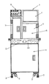
図1の装置構成図に示すように、本考案のBad Mark検出装置は、架台部(本体部と可動部とコンベア部)、カメラ部及び制御部からなる。
図2の正面図に示すように、本考案のBad Mark検出装置1は、固定脚2と移動キャスター3を備えた架台部4と、該架台部4の上部に設けた供給コンベア10を備えたコンベア部5と、前記架台部4の上方に設けたバッドマーク検出用の本体部6と、該本体部6の上部右側にモニター部7および上部左側にコンピュータ制御を行う制御部8とを設けている。
なお、前記本体部6の正面には左右に開閉できる点検ドア9を設けて内部の様子を目視できるようになっている。
An embodiment of the Bad Mark detection device of the present invention will be described below with reference to the accompanying drawings.
As shown in the device configuration diagram of FIG. 1, the Bad Mark detection device of the present invention includes a gantry unit (a main body unit, a movable unit, and a conveyor unit), a camera unit, and a control unit.
As shown in the front view of FIG. 2, the Bad Mark detection device 1 of the present invention includes a
An
図3の平面図に示すように、前記本体部6内部にはPCB(歪のない)基板又はFPC(フレキシブル)基板を供給するコンベア部5が前記架台部4上部に設けており、LED照明部11を前記コンベア部5の搬入口上側および搬出口上側の側壁に相対向するように一対ずつ設ける。
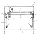
前記LED照明部11は、矩形状の照明枠内に多数の、例えば6列×18個のLEDを配列し、図4の図3A−A矢視要部断面図に示すように、前記コンベア部5の搬入口上側および搬出口上側の取付案内レール17に支持板18により相対向するように一対ずつ設ける。本実施例の場合には3対を設けているが、これに限らず適宜設計変更することができる。
また、前記取付案内レール17に固定している固定ビス19を緩めて前記支持板18の位置を変更、すなわち基板の種類に応じて位置変更することができる。
As shown in the plan view of FIG. 3, a
The LED
Further, the
前記本体部6の上方の天井部には正面側(図3では下側)および背面側(図3では上側)に沿って設けたX軸案内ガイドレール12と該X軸案内ガイドレール12と並行に沿ってX軸タイミングベルト13を設け、前記X軸案内ガイドレール12,12間に跨らせた移動支持部材14を設ける。前記移動支持部材14は前記X軸タイミングベルト13に固定されて前記X軸案内ガイドレール12に沿ってX軸方向へ移動可能となっている。
また、前記移動支持部材14と並行に沿ってY軸タイミングベルト15を設け、前記移動支持部14に移動可能に支持されたカメラ部16を設け、該カメラ部16は前記Y軸タイミングベルト15に固定されて前記移動支持部14に沿ってY軸方向へ移動可能となっている。前記カメラ部16のカメラは、CCDモノクロカメラ1台を使用している。
異なる基板サイズが対象となった場合、定めた横幅220mm×縦幅200mmの撮像サイズで撮像し、最大横幅510mm×縦幅460mmの基板サイズの場合は、9枚の画像を撮影する。すなわち、合成には重複する画像合わせ幅が必要になり、9分割の撮影画像になり、その後画像合成して求められる1枚の画像にする。
An X-axis
Further, a Y-
When different substrate sizes are targeted, images are captured with a defined image size of 220 mm wide × 200 mm wide, and nine images are captured when the substrate size is 510 mm wide × 460 mm wide. In other words, overlapping image alignment widths are required for composition, resulting in a nine-division photographed image that is then combined into one image.
図5の平面図に示すように、前記架台部4の上部に設けたコンベア部5は、正面側(図5では下側)に固定テーブル20および背面側(図5では上側)に可動テーブル21を備え、前記架台部4に設けたモータ22により駆動されるタイミングベルト23を介して前記可動テーブル21側の駆動プーリ24を駆動する。前記駆動プーリ24にはネジ軸25が固定されており、前記ネジ軸25の回転により前記可動テーブル21が前後方向に移動される。前記固定テーブル20と可動テーブル21との間には、キー溝26を有する案内軸27と供給コンベア10を駆動するコンベア駆動プーリ28を案内するスプライン軸29を架設している。
前記ネジ軸25を回転させることで前記可動テーブル21が前後移動可能であり、基板サイズが異なる場合、横幅50mm×縦幅50mm〜横幅510mm×縦幅460mmまで設定することができる。
As shown in the plan view of FIG. 5, the
When the movable table 21 can be moved back and forth by rotating the
図6のソフトウエア構想図に示すように、前記制御部8は、モデル画像の登録及び検査位置を設定する設定プログラムと、検査手順を実行する検査プログラムと、帳票を作成する帳票作成プログラムとをそれぞれ備えており、コンピュータにより設定データ、検出結果、帳票の制御を行う。
図7の動作フロー図に示すように、前記設定プラグラムでは、1.モデル画像を分割撮影し、2.分割撮影した画像から合成画像を作成(モデル画像の登録)し、3.モデル画像に検査位置を設定し、4.これらの設定データを保存する。
図8のフローチャート図に示すように、前記検査部ログラムでは、1.検査基板を搬入し、2.検査基板の品種情報から設定データを設定し、設定データを読込む、3.カメラを撮影位置に移動し、4.分割撮影し、分割撮影した画像から合成画像を作成し、この合成画像を登録し、5.合成画像と登録画像と比較し、バッドマークを検出し、6.基板を排出する。
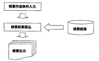
図9のフローチャート図に示すように、前記帳票作成プログラムでは、1.帳票作成条件を入力し、2.検査結果を読込み、3.帳票を出力する。
As shown in the software conceptual diagram of FIG. 6, the control unit 8 includes a setting program for registering a model image and setting an inspection position, an inspection program for executing an inspection procedure, and a form creation program for creating a form. Each is provided, and the setting data, detection results, and forms are controlled by a computer.
As shown in the operation flow diagram of FIG. 1. Take a model image separately, 2. Create a composite image (register model image) from the divided images, 3. Set the inspection position in the model image. Save these settings data.
As shown in the flowchart of FIG. 1. Carry in the inspection board. 2. Set the setting data from the type information of the inspection board and read the setting data. 3. Move the camera to the shooting position; 4. Take a divided image, create a composite image from the divided image, register this composite image, 5. Compare the synthesized image with the registered image to detect bad marks; Eject the substrate.
As shown in the flowchart of FIG. Enter the form creation conditions, and 2. 2. Read the test results. Output a form.
次に、本考案のBad Mark検出装置の操作動作を添付図面に基づいて、以下に説明する。
図3、図4に示すBad Mark検出装置1の本体部6の右側からPCB基板又はFPC基板が供給され、供給コンベア10で本体部6内へ運ばれた後、前記基板は検知センサー(図示せず)により検知されて前記供給コンベア10が停止され、基準位置に位置決めされる。
図8のフローチャート図に示すように、搬入された検査基板はバーコード読み取りが行われ、品種情報から設定データを設定し、制御部8に読み込む。
前記制御部8ではすでに、設定プラグラムにより、1.モデル画像を分割撮影し、2.分割撮影した画像から合成画像を作成(モデル画像の登録)し、3.モデル画像に検査位置を設定し、4.これらの設定データを保存している。
また、前記本体部6の内部でそれぞれ一対となっている全てのLED照明部11は点灯されており、撮像準備が完了している。
Next, the operation of the Bad Mark detection device of the present invention will be described below with reference to the accompanying drawings.
3 and FIG. 4, a PCB board or FPC board is supplied from the right side of the main body 6 of the Bad Mark detection apparatus 1 and is carried into the main body 6 by the
As shown in the flowchart of FIG. 8, the inspection board that has been loaded is subjected to barcode reading, setting data is set from the product type information, and is read into the control unit 8.
The control unit 8 has already set 1. 1. Take a model image separately, 2. Create a composite image (register model image) from the divided images, 3. Set the inspection position in the model image. These setting data are stored.
In addition, all the
前記制御部8の検査プログラムにより、カメラ部16の撮像が開始され、前記カメラ部16を基準位置に移動する。分割撮像作業中、前記カメラ部16はX軸案内ガイドレール12に沿ってX軸方向へ移動し、終端でY軸方向へ所定距離移動し再びX軸方向へ移動して戻り、このようにして繰り返し往復移動運動を行い、多数枚の分割撮像を行う。
分割撮像した画像に特殊合成画像処理を行った後、この合成撮像画像と登録画像とを比較し、バッドマークを検出してバッドマーク検出情報を取得し、前記検査基板は供給コンベア10の起動によって搬出される。
そして、前記カメラ部16は初期状態位置へ戻り、バッドマーク検出情報は次工程のCMシリーズ(実装ステーション)へ送信される。
図4に示すように、前記LED照明部11のLED光は水平に照射され、供給コンベア10上の前記基板(図示せず)に直接照射されないので、反射光が前記カメラ部16へ直接入射することがなく、前記基板に印加されたバッドマークを確実に撮像検出することができる。
Imaging by the
After performing the special composite image processing on the divided captured image, the composite captured image is compared with the registered image, the bad mark is detected and the bad mark detection information is acquired. It is carried out.
Then, the
As shown in FIG. 4, the LED light of the
1 Bad Mark検出装置
2 固定脚
3 移動キャスター
4 架台部
5 コンベア部
6 本体部
7 モニター部
8 制御部
9 点検ドア
10 供給コンベア
11 LED照明部
12 X軸案内ガイドレール
13 X軸タイミングベルト
14 移動支持部
15 Y軸タイミングベルト
16 カメラ部
17 取付案内レール
18 支持板
19 固定ビス
20 固定テーブル
21 可動テーブル
22 モータ
23 タイミングベルト
24 駆動プーリ
25 ネジ軸
26 キー溝
27 案内軸
28 コンベア駆動プーリ
29 スプライン軸
DESCRIPTION OF SYMBOLS 1 Bad Mark detection apparatus 2 Fixed leg 3 Moving
Claims (6)
Priority Applications (2)
| Application Number | Priority Date | Filing Date | Title |
|---|---|---|---|
| JP2010006974U JP3165153U (en) | 2010-10-19 | 2010-10-19 | BadMark detector |
| CN2010206362287U CN201965632U (en) | 2010-10-19 | 2010-12-01 | Bad plate mark detecting device |
Applications Claiming Priority (1)
| Application Number | Priority Date | Filing Date | Title |
|---|---|---|---|
| JP2010006974U JP3165153U (en) | 2010-10-19 | 2010-10-19 | BadMark detector |
Publications (1)
| Publication Number | Publication Date |
|---|---|
| JP3165153U true JP3165153U (en) | 2011-01-06 |
Family
ID=44534960
Family Applications (1)
| Application Number | Title | Priority Date | Filing Date |
|---|---|---|---|
| JP2010006974U Expired - Lifetime JP3165153U (en) | 2010-10-19 | 2010-10-19 | BadMark detector |
Country Status (2)
| Country | Link |
|---|---|
| JP (1) | JP3165153U (en) |
| CN (1) | CN201965632U (en) |
Cited By (4)
| Publication number | Priority date | Publication date | Assignee | Title |
|---|---|---|---|---|
| CN102353682A (en) * | 2011-07-01 | 2012-02-15 | 深圳市日联科技有限公司 | On-the-spot online automatic optical detection equipment and method |
| EP2914080A1 (en) | 2014-02-26 | 2015-09-02 | JUKI Corporation | Electronic component mounting apparatus and electronic component mounting method |
| CN108760753A (en) * | 2018-05-31 | 2018-11-06 | 永捷电子(始兴)有限公司 | Mark point detection devices and its detection method |
| JP2021170618A (en) * | 2020-04-17 | 2021-10-28 | 積進工業株式会社 | General-purpose badmark detection device |
Families Citing this family (1)
| Publication number | Priority date | Publication date | Assignee | Title |
|---|---|---|---|---|
| CN107167478A (en) * | 2017-04-25 | 2017-09-15 | 明基材料有限公司 | Piece face internal labeling detection method and device |
-
2010
- 2010-10-19 JP JP2010006974U patent/JP3165153U/en not_active Expired - Lifetime
- 2010-12-01 CN CN2010206362287U patent/CN201965632U/en not_active Expired - Lifetime
Cited By (8)
| Publication number | Priority date | Publication date | Assignee | Title |
|---|---|---|---|---|
| CN102353682A (en) * | 2011-07-01 | 2012-02-15 | 深圳市日联科技有限公司 | On-the-spot online automatic optical detection equipment and method |
| CN102353682B (en) * | 2011-07-01 | 2013-06-12 | 深圳市日联科技有限公司 | On-the-spot online automatic optical detection equipment and method |
| EP2914080A1 (en) | 2014-02-26 | 2015-09-02 | JUKI Corporation | Electronic component mounting apparatus and electronic component mounting method |
| US9949418B2 (en) | 2014-02-26 | 2018-04-17 | Juki Corporation | Electronic component mounting apparatus and electronic component mounting method |
| CN108760753A (en) * | 2018-05-31 | 2018-11-06 | 永捷电子(始兴)有限公司 | Mark point detection devices and its detection method |
| CN108760753B (en) * | 2018-05-31 | 2023-12-12 | 永捷电子(始兴)有限公司 | Mark point detection device and detection method thereof |
| JP2021170618A (en) * | 2020-04-17 | 2021-10-28 | 積進工業株式会社 | General-purpose badmark detection device |
| JP7339922B2 (en) | 2020-04-17 | 2023-09-06 | 積進工業株式会社 | General-purpose BadMark detector |
Also Published As
| Publication number | Publication date |
|---|---|
| CN201965632U (en) | 2011-09-07 |
Similar Documents
| Publication | Publication Date | Title |
|---|---|---|
| JP3165153U (en) | BadMark detector | |
| CN109991166B (en) | Equipment for detecting product appearance defects and combined light source device and method thereof | |
| US8983030B2 (en) | Inspection machine for printed circuit board | |
| JP4866782B2 (en) | Substrate clamping mechanism and drawing system | |
| CN207894379U (en) | A kind of CCD vision inspection apparatus | |
| US9140546B2 (en) | Apparatus and method for three dimensional inspection of wafer saw marks | |
| JP5881244B2 (en) | Component mounting apparatus, board detection method, and board manufacturing method | |
| KR101454823B1 (en) | Visual inspection apparatus | |
| JP2014508938A (en) | Vision inspection equipment using multiple grid patterns | |
| KR20090033031A (en) | Substrate surface inspection apparatus | |
| CN108225214A (en) | A kind of CCD vision inspection apparatus and detection method | |
| CN113418933B (en) | Flying shooting visual imaging detection system and method for detecting large-size object | |
| CN112150539B (en) | Chain pitch detection device and method based on double cameras | |
| WO2014201719A1 (en) | Detecting apparatus and detecting method | |
| JP2007294727A (en) | Imaging apparatus, surface mount machine using the same, component test device, and screen printing device | |
| JP6164603B2 (en) | Nondestructive inspection equipment | |
| TW201712325A (en) | Electronic component transfer device and electronic component inspection device | |
| JP6823156B2 (en) | Backup pin recognition method and component mounting device | |
| KR101111065B1 (en) | Apparatus for inspecting substrate | |
| CN206818162U (en) | Optical measuring apparatus | |
| JP2007334423A (en) | Automatic photographing device | |
| KR101314592B1 (en) | Vision inspection apparatus of improved inspection speed | |
| JP4942188B2 (en) | Substrate clamping mechanism and drawing system | |
| JP3162974U (en) | BadMark detection device | |
| JP2012194067A (en) | Surface inspection device |
Legal Events
| Date | Code | Title | Description |
|---|---|---|---|
| R150 | Certificate of patent or registration of utility model |
Ref document number: 3165153 Country of ref document: JP Free format text: JAPANESE INTERMEDIATE CODE: R150 Free format text: JAPANESE INTERMEDIATE CODE: R150 |
|
| FPAY | Renewal fee payment (event date is renewal date of database) |
Free format text: PAYMENT UNTIL: 20131208 Year of fee payment: 3 |
|
| A623 | Registrability report |
Free format text: JAPANESE INTERMEDIATE CODE: A623 Effective date: 20101219 |
|
| R250 | Receipt of annual fees |
Free format text: JAPANESE INTERMEDIATE CODE: R250 |
|
| R250 | Receipt of annual fees |
Free format text: JAPANESE INTERMEDIATE CODE: R250 |
|
| R250 | Receipt of annual fees |
Free format text: JAPANESE INTERMEDIATE CODE: R250 |
|
| R250 | Receipt of annual fees |
Free format text: JAPANESE INTERMEDIATE CODE: R250 |
|
| R250 | Receipt of annual fees |
Free format text: JAPANESE INTERMEDIATE CODE: R250 |
|
| R250 | Receipt of annual fees |
Free format text: JAPANESE INTERMEDIATE CODE: R250 |
|
| R250 | Receipt of annual fees |
Free format text: JAPANESE INTERMEDIATE CODE: R250 |