KR20090033031A - Substrate surface inspection apparatus - Google Patents
Substrate surface inspection apparatus Download PDFInfo
- Publication number
- KR20090033031A KR20090033031A KR1020080093754A KR20080093754A KR20090033031A KR 20090033031 A KR20090033031 A KR 20090033031A KR 1020080093754 A KR1020080093754 A KR 1020080093754A KR 20080093754 A KR20080093754 A KR 20080093754A KR 20090033031 A KR20090033031 A KR 20090033031A
- Authority
- KR
- South Korea
- Prior art keywords
- substrate
- board
- speed
- inspection
- light receiving
- Prior art date
Links
Images


Classifications
-
- G—PHYSICS
- G02—OPTICS
- G02F—OPTICAL DEVICES OR ARRANGEMENTS FOR THE CONTROL OF LIGHT BY MODIFICATION OF THE OPTICAL PROPERTIES OF THE MEDIA OF THE ELEMENTS INVOLVED THEREIN; NON-LINEAR OPTICS; FREQUENCY-CHANGING OF LIGHT; OPTICAL LOGIC ELEMENTS; OPTICAL ANALOGUE/DIGITAL CONVERTERS
- G02F1/00—Devices or arrangements for the control of the intensity, colour, phase, polarisation or direction of light arriving from an independent light source, e.g. switching, gating or modulating; Non-linear optics
- G02F1/01—Devices or arrangements for the control of the intensity, colour, phase, polarisation or direction of light arriving from an independent light source, e.g. switching, gating or modulating; Non-linear optics for the control of the intensity, phase, polarisation or colour
- G02F1/13—Devices or arrangements for the control of the intensity, colour, phase, polarisation or direction of light arriving from an independent light source, e.g. switching, gating or modulating; Non-linear optics for the control of the intensity, phase, polarisation or colour based on liquid crystals, e.g. single liquid crystal display cells
- G02F1/1306—Details
- G02F1/1309—Repairing; Testing
-
- G—PHYSICS
- G01—MEASURING; TESTING
- G01N—INVESTIGATING OR ANALYSING MATERIALS BY DETERMINING THEIR CHEMICAL OR PHYSICAL PROPERTIES
- G01N21/00—Investigating or analysing materials by the use of optical means, i.e. using sub-millimetre waves, infrared, visible or ultraviolet light
- G01N21/84—Systems specially adapted for particular applications
- G01N21/88—Investigating the presence of flaws or contamination
- G01N21/8803—Visual inspection
-
- G—PHYSICS
- G01—MEASURING; TESTING
- G01N—INVESTIGATING OR ANALYSING MATERIALS BY DETERMINING THEIR CHEMICAL OR PHYSICAL PROPERTIES
- G01N21/00—Investigating or analysing materials by the use of optical means, i.e. using sub-millimetre waves, infrared, visible or ultraviolet light
- G01N21/84—Systems specially adapted for particular applications
- G01N21/88—Investigating the presence of flaws or contamination
- G01N21/95—Investigating the presence of flaws or contamination characterised by the material or shape of the object to be examined
- G01N2021/9513—Liquid crystal panels
Abstract
Description
본 발명은 기판 외관 검사 장치에 관한 것이다.The present invention relates to a substrate appearance inspection apparatus.
종래, LCD(액정 디스플레이) 등의 제조에 사용되는 마더(mother) 유리 기판(검사 대상 기판)에 발생하는 결함 등을 검사하는 기술로서, 반송로(搬送路) 상을 이동하는 검사 대상 기판의 화상을 촬상하여 검사를 행하는 검사 장치가 알려져 있다(하기 특허 문헌 1 및 특허 문헌 2 참조).Background Art Conventionally, a technique for inspecting defects or the like that occur in a mother glass substrate (inspection substrate) used for manufacturing LCD (liquid crystal display), etc., which is an image of an inspection object substrate moving on a conveying path. BACKGROUND ART Inspection apparatuses for imaging and inspecting are known (see Patent Document 1 and Patent Document 2 below).
하기 특허 문헌 1의 검사 장치는, 검사 대상 기판이 촬영 시야 내의 소정의 위치에 도달하기 전에, 검사 대상 기판의 위치와 도달 소요 시간을 구함으로써, 촬영 소정 위치에서 검사 대상 기판의 전체를 촬영하여 매크로 검사를 행하고 있다.In the inspection apparatus of the following Patent Document 1, before the inspection target substrate reaches a predetermined position in the photographing field of vision, the inspection apparatus obtains the position of the inspection target substrate and the time required to arrive, thereby capturing the entire inspection target substrate at the photographing predetermined position and then macro. The test is being done.
또한, 하기 특허 문헌 2의 검사 장치는, 라인형의 촬상 소자로 구성된 촬상 수단과 촬영 대상물을 직교 방향으로 이동시키고, 촬상된 라인형의 화상으로부터 전체 화상을 작성하여 매크로 검사를 행하고 있다.Moreover, the inspection apparatus of the following patent document 2 carries out macro inspection by moving the imaging means comprised with a linear image pick-up element, and a photographing target in a orthogonal direction, creating a whole image from the image of the linear image picked up.
[특허 문헌 1] 일본 특허출원 공개번호 1996-313454호 공보[Patent Document 1] Japanese Patent Application Publication No. 1996-313454
[특허 문헌 2] 일본 특허출원 공개번호 1998-260139호 공보[Patent Document 2] Japanese Patent Application Publication No. 1998-260139
여기서, 전술한 LCD를 포함하는 FPD(플랫 패널 디스플레이)의 제조 공정 및 검사 공정에 있어서의 인라인의 각종 제조 장치나 검사 장치에 있어서는, 새로운 공정 시간을 단축하고 검사 효율을 향상시키는 것이 요구되고 있다.Here, in various in-line manufacturing apparatuses and inspection apparatuses in the manufacturing process and inspection process of the FPD (flat panel display) containing LCD mentioned above, it is calculated | required to shorten a new process time and to improve inspection efficiency.
그러나, 전술한 바와 같은 특허 문헌 1 및 특허 문헌 2의 검사 장치에서는, 촬상 대상 기판의 반송 속도를 고속으로 한 경우에, 촬영 대상 기판의 양호한 화상을 얻기 위해서는, 감도가 높은 카메라나 화상 신호의 처리를 고속으로 행할 수 있는 시스템 등이 필요해진다.However, in the inspection apparatus of the above-mentioned patent documents 1 and patent documents 2, when the conveyance speed of an imaging target board | substrate is made high speed, in order to obtain the favorable image of a photographing target board | substrate, processing of a camera or image signal with high sensitivity is carried out. There is a need for a system capable of performing the operation at high speed.
또한, 촬영 대상 기판의 화상을 밝게 하여 노이즈가 적은 화상으로서 취득하기 위해서는, 고감도의 밝은 조명을 균일하게 촬상 범위에 조사(照射)할 수 있는 조명 장치 등도 필요해진다.In addition, in order to brighten the image of the photographing target substrate and acquire it as an image having low noise, an illumination device or the like capable of irradiating high-sensitivity bright illumination uniformly to the imaging range is also required.
이와 같은 문제는, 검사 대상 기판이 이동하는 반송로의 스피드가 빨라지면 질수록, 또한 검사 대상 기판의 매크로 검사의 정밀도를 추구하면 할수록, 시스템이나 조명 장치에 요구되는 조건이 엄격해 진다.Such a problem becomes severer as the speed of the conveyance path to which the inspection target substrate moves moves and the accuracy of macro inspection of the inspection target substrate is pursued.
본 발명은, 이와 같은 문제점을 해결하기 위한 것으로서, 고가이며 고성능의 장치를 사용하지 않고, 보다 염가의 구성으로 반송로 상에 반송되어 오는 검사 대상 기판의 선명한 화상을 보다 염가의 구성으로 얻을 수 있고, 매크로 검사를 양호한 정밀도로 행할 수 있는 기판 외관 검사 장치를 제공하는 것을 목적으로 한다.SUMMARY OF THE INVENTION The present invention has been made to solve such a problem, and it is possible to obtain a clear image of an inspection target substrate conveyed on a conveying path with a more inexpensive configuration without using an expensive and high-performance device in a more inexpensive configuration. An object of the present invention is to provide a substrate appearance inspection apparatus capable of performing macro inspection with good accuracy.
상기 과제를 해결하기 위하여, 본 발명은 이하의 수단을 채용한다.In order to solve the said subject, this invention employ | adopts the following means.
본 발명은, 검사 대상 기판을 일정 방향을 따라 이동시키는 기판 반송 수단과, 상기 검사 대상 기판에 대하여 조명광(照明光)을 출사하는 조명 수단과, 상기 조명 수단으로부터 출사되고 상기 검사 대상 기판에서 반사된 반사광 또는 상기 검사 대상 기판을 투과한 투과광을 수광하는 수광 수단과, 상기 조명 수단 및 상기 수광 수단을 일체로 이동시키는 이동 수단과, 상기 이동 수단의 구동을 제어하는 제어 수단을 포함하고, 상기 제어 수단은 상기 이동 수단에 의한 상기 조명 수단 및 상기 수광 수단의 이동이 상기 검사 대상 기판의 이동 방향과 동일한 방향을 따라 이동되는 기판 외관 검사 장치를 제공한다.The present invention provides a substrate conveying means for moving a substrate to be inspected in a predetermined direction, illumination means for emitting illumination light with respect to the substrate to be inspected, and light emitted from the illumination means and reflected from the substrate to be inspected. Light receiving means for receiving reflected light or transmitted light transmitted through the inspection target substrate, moving means for integrally moving the illumination means and the light receiving means, and control means for controlling the driving of the moving means; Provides a substrate appearance inspection apparatus in which movement of the illumination means and the light receiving means by the movement means is moved along the same direction as the movement direction of the inspection target substrate.
본 발명에 의하면, 기판 반송 수단의 작동에 의해 이동되는 검사 대상 기판에 대하여, 조명 수단의 작동에 의해 조명광이 출사되고, 그 반사광 또는 투과광이 수광 수단에 의해 수광된다.According to the present invention, the illumination light is emitted by the operation of the illumination means to the inspection target substrate moved by the operation of the substrate conveyance means, and the reflected light or transmitted light is received by the light receiving means.
이 경우에, 이동 수단의 작동에 의해, 조명 수단 및 수광 수단이 일체로 이동되는 동시에, 제어부의 작동에 의해, 조명 수단 및 수광 수단이 검사 대상 기판의 이동 방향과 동일한 방향을 따라 이동되므로, 검사 대상 기판에 대한 조명 수단 및 수광 수단의 상대 속도를 작게 할 수 있다.In this case, the illumination means and the light receiving means are moved integrally by the operation of the moving means, and the illumination means and the light receiving means are moved along the same direction as the moving direction of the inspection target substrate by the operation of the control unit. The relative speed of the lighting means and the light receiving means with respect to the target substrate can be made small.
따라서, 검사 대상 기판, 또는 조명 수단 및 수광 수단 중 어느 하나를 정지하여 촬상하는 경우에 비하여, 검사 대상 기판의 전체면에 걸쳐서 고해상도의 화상을 얻을 수 있어, 검사 대상 기판을 양호하게 매크로 검사할 수 있다. 이로써, 예를 들면, 촬영 수단의 노광 시간을 길게 해도, 반사광 또는 투과광을 흔들리지 않 고 촬영할 수 있고, 또한 선명한 화상을 얻는 것이 가능해진다. 또한, 검사 대상 기판을 반송하면서 매크로 검사를 행할 수 있고, 검사 대상 기판의 반송에 필요한 시간을 유효하게 이용하여, 택트 타임을 단축할 수 있다.Therefore, a high resolution image can be obtained over the entire surface of the inspection target substrate as compared with the case where the inspection target substrate, or any one of the illumination means and the light receiving means is imaged, so that the inspection target substrate can be macroscopically inspected. have. Thereby, for example, even if the exposure time of the photographing means is extended, it is possible to photograph the reflected light or transmitted light without shaking, and to obtain a clear image. In addition, the macro inspection can be performed while conveying the inspection target substrate, and the tact time can be shortened by effectively utilizing the time required for carrying the inspection target substrate.
상기 발명에 있어서는, 상기 기판 반송 수단은 상기 검사 대상 기판을 일정한 속도로 이동시키는 구성이라도 된다.In the said invention, the said board | substrate conveyance means may be a structure which moves the said test subject board | substrate at a fixed speed.
이와 같이 구성함으로써, 흔들림이 적은 선명한 화상을 얻기 쉬워, 매크로 검사의 정밀도를 향상시킬 수 있다.By configuring in this way, a clear image with few shaking is easy to be obtained, and the precision of macro inspection can be improved.
또한, 상기 발명에 있어서는, 상기 조명 수단과 상기 수광 수단을 일체로 구성하는 검사 유닛과, 상기 검사 대상 기판의 반송 방향을 따라 평행하게 설치되고 상기 검사 유닛의 이동을 안내하는 안내 수단을 가지는 구성이라도 된다.Moreover, in the said invention, even if it is the structure which has the inspection unit which comprises the said illumination means and the said light receiving means integrally, and the guide means provided in parallel along the conveyance direction of the said inspection target board | substrate, and guides the movement of the said inspection unit, do.
이와 같이 구성함으로써, 검사 유닛에 의해 조명 수단과 수광 수단의 위치 관계를 안정시켜, 수광 수단에 의한 조명 수단으로부터의 조명광의 수광을 양호한 정밀도로 행할 수 있다. 또한, 안내 수단에 의해 조명 수단 및 수광 수단이 검사 대상 기판의 반송 방향을 따라 안내되므로, 조명 수단 및 수광 수단을 검사 대상 기판과 동일한 방향으로 용이하고 정확하게 이동시킬 수 있다.By such a configuration, the positional relationship between the lighting means and the light receiving means can be stabilized by the inspection unit, and the light receiving means can receive the illumination light from the lighting means with good accuracy. In addition, since the illuminating means and the light receiving means are guided along the conveying direction of the inspection target substrate by the guide means, the illuminating means and the light receiving means can be easily and accurately moved in the same direction as the inspection target substrate.
또한, 상기 발명에 있어서는, 상기 조명 수단이 라인 조명 광원이며, 상기 수광 수단이 라인 센서인 구성으로 해도 된다.Moreover, in the said invention, it is good also as a structure in which the said lighting means is a line illumination light source, and the said light receiving means is a line sensor.
이와 같이 구성함으로써, 라인 조명 광원에 의해 검사 대상 기판의 이동 방향과 직교하는 선형의 조명광을 검사 대상 기판에 조사하고, 라인 센서에 의해 그 선형의 조명광을 수광하는 것만으로, 조명 수단 및 수광 수단을 검사 대상 기판의 반송 방향의 폭방향으로 주사(走査)하지 않아도, 반송 중인 검사 대상 기판을 그 전체면에 걸쳐 효율적으로 촬상할 수 있다.By such a configuration, the illuminating means and the light receiving means are only irradiated with the linear illumination light orthogonal to the inspection object substrate by the line illumination light source and the linear illumination light is received by the line sensor. Even if it does not scan in the width direction of the conveyance direction of an inspection object board | substrate, the inspection object board | substrate currently conveyed can be imaged efficiently over the whole surface.
또한, 상기 발명에 있어서는, 상기 검사 대상 기판의 반송 속도를 검출하는 속도 검출 수단을 더 포함하고, 상기 제어 수단은 상기 속도 검출 수단에 의해 검출된 상기 검사 대상 기판의 반송 속도에 따라 상기 이동 수단을 제어하는 구성이라도 된다.The invention further includes a speed detecting means for detecting a conveying speed of the inspection target substrate, wherein the control means moves the moving means in accordance with the conveying speed of the inspection target substrate detected by the speed detecting means. The control structure may be sufficient.
이와 같이 구성함으로써, 검사 대상 기판의 반송 속도가 변화되어도, 속도 검출 수단에 의해 그 반송 속도가 검출되어, 제어 수단의 작동에 의해 조명 수단 및 촬영 수단의 이동 속도가 변동되므로, 검사 대상 기판에 대한 조명 수단 및 수광 수단의 상대 속도를 임의로 제어할 수 있다. 이로써, 검사 대상 기판의 반송 속도를 저하시키지 않아도, 촬상 수단의 촬상 조건이나 검사 대상 기판의 결함의 크기에 따라 상대 속도를 조정할 수 있어, 택트 타임을 효과적으로 단축할 수 있다.With this arrangement, even if the conveyance speed of the inspection target substrate is changed, the conveyance speed is detected by the speed detection means, and the movement speeds of the illumination means and the imaging means are changed by the operation of the control means, so that The relative speed of the lighting means and the light receiving means can be arbitrarily controlled. Thereby, a relative speed can be adjusted according to the imaging conditions of an imaging means or the magnitude | size of the defect of a test target board | substrate, without reducing the conveyance speed of a test target board | substrate, and a tact time can be shortened effectively.
또한, 상기 발명에 있어서는, 상기 제어 수단은, 상기 검사 대상 기판에 대한 상기 조명 수단 및 상기 수광 수단의 상대 속도를, 상기 검사 대상 기판의 반송 속도보다 낮은 정속도(定速度)로 되도록 제어하는 것이라도 된다.Moreover, in the said invention, the said control means controls the relative speed of the said illumination means and the said light receiving means with respect to the said inspection target board | substrate so that it may become a fixed speed lower than the conveyance speed of the said inspection target board | substrate. You may also
이와 같이 구성함으로써, 제어 수단의 작동에 의해, 검사 대상 기판에 대한 조명 수단 및 수광 수단의 상대 속도가 항상 정속도로 유지되므로, 검사 대상 기판의 반송 속도가 변화되어도 선명한 화상을 얻을 수 있다.With this arrangement, since the relative speeds of the illumination means and the light receiving means with respect to the inspection target substrate are always maintained at a constant speed by the operation of the control means, a clear image can be obtained even if the conveyance speed of the inspection target substrate is changed.
또한, 상기 발명에 있어서는, 상기 조명 수단 및 상기 수광 수단의 이동 속 도는, 상기 검사 대상 기판의 반송 속도보다 저속도로 설정되는 구성이라도 된다.In the above invention, the movement speed of the illumination means and the light receiving means may be configured to be set at a lower speed than the conveyance speed of the inspection target substrate.
이와 같이 구성함으로써, 조명 수단 및 수광 수단을 정지하여 검사 대상 기판을 매크로 검사하는 경우에 비하여, 수광 수단의 성능을 낮춰도 선명한 화상을 얻을 수 있다.With such a configuration, a clear image can be obtained even if the performance of the light receiving means is lowered as compared with the case where the illumination means and the light receiving means are stopped and macro inspection of the inspection target substrate is performed.
또한, 상기 발명에 있어서는, 상기 조명 수단 및 상기 수광 수단의 이동 속도는, 상기 검사 대상 기판의 반송 속도보다 고속도로 설정되는 것이라도 된다.In addition, in the said invention, the moving speed of the said illumination means and the said light receiving means may be set to the highway rather than the conveyance speed of the said inspection target board | substrate.
이와 같이 구성함으로써, 조명 수단 및 상기 수광 수단을 통과시켜 검사 대상 기판을 검사한 후에, 조명 수단 및 수광 수단을 고속도로 변경하여 검사 대상 기판의 전방으로 이동시킴으로써, 동일한 검사 대상 기판을 재차 촬상할 수 있다. 이로써, 예를 들면, 1번째의 촬상으로 결함이 검출된 검사 대상 기판을, 다시 고감도의 촬상 조건으로 촬상할 수 있어, 결함 부분의 검사를 보다 양호한 정밀도로 행할 수 있다.With such a configuration, after inspecting the inspection target substrate by passing the illumination means and the light receiving means, the same inspection target substrate can be imaged again by changing the highway and moving the front of the inspection target substrate. . Thereby, for example, the inspection target board | substrate with which the defect was detected by the 1st imaging can be image | photographed again by the high sensitivity imaging conditions, and inspection of a defect part can be performed with more accurate.
또한, 상기 발명에 있어서는, 상기 조명 수단 및 상기 수광 수단의 이동 속도는, 상기 검사 대상 기판의 반송 속도와 동일 속도로 설정되는 것이라도 된다.In addition, in the said invention, the moving speed of the said illumination means and the said light receiving means may be set to the same speed as the conveyance speed of the said inspection target board | substrate.
이와 같이 구성함으로써, 조명 수단 및 수광 수단에 대하여, 검사 대상 기판을 상대적으로 정지한 상태에서 촬상할 수 있다. 따라서, 고성능의 수광 수단을 사용하지 않아도, 검사 대상 기판의 검사하고자 하는 부분을 더욱 정밀하게 검사할 수 있다.By such a configuration, the illumination target and the light receiving means can be imaged in a state where the inspection target substrate is relatively stopped. Therefore, even if a high performance light receiving means is not used, the part to be inspected of the inspection target substrate can be inspected more precisely.
또한, 상기 발명에 있어서는, 상기 수광 수단은, 2차원 촬상 소자를 구비하는 카메라인 것으로 해도 된다.Moreover, in the said invention, the said light receiving means may be a camera provided with a two-dimensional imaging element.
이와 같이 구성함으로써, 검사 대상 기판의 2차원적 화상을 취득하여, 검사 대상 기판의 매크로 검사를 신속하고 광범위하게 행할 수 있다.By such a configuration, a two-dimensional image of the inspection target substrate can be obtained, and the macro inspection of the inspection target substrate can be performed quickly and extensively.
본 발명에 의하면, 고성능의 장치를 사용하지 않고, 반송로 상에 반송되어 오는 검사 대상 기판의 선명한 화상을 얻어 정밀도가 양호한 매크로 검사를 행할 수 있는 효과를 얻을 수 있다.According to the present invention, it is possible to obtain an effect of obtaining a clear image of an inspection target substrate conveyed on a conveying path without using a high performance device and performing macro inspection with good precision.
〔제1 실시예〕[First Embodiment]
이하, 본 발명의 제1 실시예에 관한 기판 외관 검사 장치에 대하여, 도면을 참조하여 설명한다.EMBODIMENT OF THE INVENTION Hereinafter, the board | substrate visual inspection apparatus which concerns on 1st Example of this invention is demonstrated with reference to drawings.
본 실시예에 관한 기판 외관 검사 장치(1)는, 예를 들면, 도 6에 나타낸 바와 같은 복수개의 롤러(21)로 구성되는 컨베이어(23)를 구비하는 기판 반송로(기판 반송 수단)(25) 상, 또는 도 7에 나타낸 바와 같은 복수개의 분출구멍(27)을 가지는 부상(浮上) 플레이트(29)를 구비하는 기판 반송로(31) 상에 반송되어 오는 FPD를 제조하는 마더 유리 기판(검사 대상 기판, 이하, "기판"이라고 함)(33)의 전체면을 촬상하여 매크로 검사하기 위한 장치이다.The board | substrate visual inspection apparatus 1 which concerns on a present Example is the board | substrate conveyance path (substrate conveying means) 25 provided with the
기판 외관 검사 장치(1)는, 도 1 및 도 2에 나타낸 바와 같이, 기판(33)을 제조하는 제조 장치 사이를 연결하는 기판 반송로(25)와, 상기 기판 반송로(25) 상을 소정의 반송 속도로 반송되어 오는 기판(33) 표면의 외관을 검사하는 검사 장치 유닛(검사 유닛)(3)과, 상기 검사 장치 유닛(3)을 탑재하는, 예를 들면 리니어 가 이드나 롤러 가이드 등으로 구성되는 가이드(안내 수단)(5)와, 상기 가이드(5)에 따라 검사 장치 유닛(3)을 기판 반송로(25)의 반송 방향으로 이동시키는, 예를 들면, 리니어 모터 등의 직선 구동 기구로 이루어지는 구동부(이동 수단)(7)와, 기판(33)의 반송 속도를 검출하는 속도 검출부(속도 검출 수단)(9)와, 구동부(7)를 제어하는 제어부(제어 수단)(11)를 구비하고 있다.As shown in FIG. 1 and FIG. 2, the board | substrate external appearance inspection apparatus 1 determines the board |
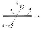
검사 장치 유닛(3)은, 기판(33)의 표면에 조사하는 조명광을 발생하는 조명부(조명 수단)(13)와, 상기 조명부(13)로부터 출사되어 기판(33)의 표면에서 반사된 반사광을 촬영하는 촬상부(수광 수단)(15)를 구비하고 있다.The
조명부(13)는, 예를 들면, 기판(33)의 반송 방향과 직교하는 선형의 조명광을 조사하는 라인 조명 광원이다. 조명부(13)는, 기판 반송로(25)의 상부에서, 후술하는 촬상부(15)의 소정의 위치 관계를 갖도록 설치되고, 기판(33)의 표면에 대하여 조명광의 광축이 소정의 경사 각도로 경사지게 배치되어 있다.The
촬상부(15)는, 예를 들면, 1차원 배열된 복수개의 화소를 가지는 라인 센서로 구성되지만, 이외에도, 2차원 배열된, 예를 들면, CCD나 CMOS 등의 수광 소자를 가지는 2차원 센서 카메라라도 상관없다. 촬상부(15)는, 기판 반송로(25)의 상부에 위치하도록 설치되고, 복수개의 화소가 기판 반송로(25) 상의 기판(33)의 표면에 대하여, 그 광축을 소정의 경사 각도로 경사지게 하고, 조명부(13)에 의한 조명 범위의 중심에 광축을 일치시키도록 배치되어 있다.The
조명부(13)와 촬상부(15)의 위치 관계는, 기판(33)의 면 상에서의 수직선에 대하여, 조명광의 입사각과 촬상부(15)가 촬상하는 반사광의 반사각이 같은 배치로 되어 간섭광을 촬상하도록 한 위치 관계, 또는 입사각과 반사각이 상이한 배치로 되어 산란광 및 회절광을 촬상하도록 한 위치 관계이다. 이로써, 촬상부(15)는, 기판 반송로(25) 상에서 반송되는 기판(33)의 라인 스캔 화상을 순서대로 취득하도록 되어 있다.The positional relationship between the
가이드(5)는, 기판 반송로(25)의 반송 방향을 따라 평행하게 한쌍이 설치되어 있다. 검사 장치 유닛(3)은, 구동부(7)의 구동력에 의해 한쌍의 가이드(5) 상을 주행하고, 조명부(13)로부터의 조명광이 각 가이드(5) 사이를 통해 기판(33)에 조사되고, 기판(33)의 표면으로부터의 반사광이 관통구멍(5a)을 통과하여 촬상부(15)에 표시되도록 되어 있다.The pair of
구동부(7)는, 검사 장치 유닛(3)을 지지하는 본체부에 설치된 리니어 모터의 가동(可動) 전자석을 구성하는 도시하지 않은 슬라이더와, 슬라이더를 주행 구동시키는 고정 전자석을 구성하는 가이드(5)를 구비하는 리니어 모터로 이루어진다. 가이드(5) 측의 고정 전자석을 레일에 따라 차례로 구동함으로써, 검사 장치 유닛(3) 측의 가동 전자석과 고정 전자석의 작용에 의해, 검사 장치 유닛(3)을 가이드에 따라 임의의 속도로 주행시키는 것이 가능하다.The
속도 검출 장치(9)는, 기판 반송로(25) 상에 반송되는 기판(33)의 속도를 검출하고, 검출한 기판(33)의 기판 속도 신호를 제어부(11)에 출력하도록 되어 있다.The
이와 같이 구성된 본 실시예에 관한 기판 외관 검사 장치(1)의 작용에 대하여 설명한다.The effect | action of the board | substrate visual inspection apparatus 1 which concerns on this embodiment comprised in this way is demonstrated.
본 실시예에 관한 기판 외관 검사 장치(1)에 의해, 기판 반송로(25) 상에 반 송되는 기판(33)을 검사하는 데는, 먼저, 기판 반송로(25)의 기판 반입측 근방에 검사 장치 유닛(3)을 배치한다.In order to test the board |
이어서, 속도 검출 장치(9)의 작동에 의해, 기판(33)이 기판 외관 검사 장치(1)의 하부에 도달하기 전에, 기판 반송로(25) 상의 기판(33)의 반송 속도가 검출되어, 기판 속도 신호가 제어부(11)에 출력된다.Subsequently, by the operation of the
제어부(11)는, 도 3에 나타낸 바와 같이, 기판(33)이 기판 외관 검사 장치(1)의 하부에 위치했을 때, 검사 장치 유닛(3)이 기판(33)의 이동 방향과 동일한 방향으로 주행하도록 구동부(7)를 제어한다. 이 때, 검사 장치 유닛(3)의 이동 속도 SS(SS>0)가 기판(33)의 반송 속도 S(S>0)보다 작아지도록 구동부(7)를 제어한다.3, when the board |
이로써, 검사 장치 유닛(3)은, 이동 중인 기판(33)에 대하여, 상대 속도 T1(T1= S-SS)이며 기판(33)의 반송 방향을 따라 주사하게 된다. 즉, 상대 속도 T1은, 기판(33)에 대한 검사 장치 유닛(3)의 주사 속도에 상당한다. 그리고, 도면 중, 부호 A는, 기판(33) 상에서의 검출 위치를 나타내고 있다.Thereby, the test |
기판(33)에 대한 검사 장치 유닛(3)의 상대 속도를 저감함으로써, 즉 상대 속도 T1으로 제어함으로써, 촬상부(15)의 촬상 조건에 맞추어, 기판(33)에 대한 검사 장치 유닛(3)의 상대 속도 T1을 조정할 수 있다.The
검사 장치 유닛(3)에 의해 기판(33) 상의 결함이 검출된 경우, 그 결함을 보다 고해상도로 촬상하기 위하여, 검사 장치 유닛(3)의 이동 속도를 기판(33)의 반송 속도보다 높여 검사 장치 유닛(3)을 결함의 검출 개시 위치까지 되돌린다. 이 경우, 제어부(11)는, 결함이 검출된 위치와 기판(33)의 반송 속도 등의 데이터에 따라 검출 장치 유닛(3)의 검사 포인트가 반송 중인 기판(33)의 결함 위치에 도달하는 속도와 시간을 구하고, 검사 장치 유닛(3)의 검사 포인트가 결함보다 반송 방향의 약간 전방에 위치하도록 검사 장치 유닛(3)을 이동시킨다. 이 후, 제어부(11)는, 기판(33)에 대한 검사 장치 유닛(3)의 상대 속도가 최초에 설정한 상대 속도보다 지연되도록, 검사 장치 유닛(3)의 이동 속도를 조정한다.When a defect on the board |
이 결과, 촬상부(15)에 의해 기판(33)의 반송 속도보다 늦은 상대 속도 T1으로 라인 스캔 화상이 순서대로 취득됨으로써, 기판(33)의 전체면에 걸쳐 고해상도의 화상을 얻을 수 있어, 기판(33)을 양호하게 매크로 검사할 수 있다. 또한, 고해상도의 화상을 취득하기 위해 기판(33)의 반송 속도를 낮출 필요가 없기 때문에, 검사 공정에 있어서의 검사 효율이 저하되지 않는다. 또한, 결함이 검출된 경우에, 촬상 조건에 따라서는, 기판(33)에 대한 검사 장치 유닛(3)의 상대 속도 T1을 보다 늦게 함으로써 촬상부(15)의 해상도를 높여 미소한 결함을 양호하게 촬영할 수도 있다.As a result, since the line scan image is acquired in order by the
이상 설명한 바와 같이, 본 실시예에 관한 기판 외관 검사 장치(1)에 의하면, 기판(33)에 대한 검사 장치 유닛(3)의 상대 속도를 촬상부(15)의 촬상 조건에 맞추어 임의로 조정할 수 있도록 했으므로, 예를 들면, 촬상부(15)의 촬상 조건인 노광 시간을 길게 해도(또는, 셔터 스피드를 늦게 해도), 노광 시간(또는, 셔터 스피드)에 적절한 상대 속도로 되도록 검사 장치 유닛(3)의 이동 속도로 조정함으로써, 기판(33)의 표면에서 반사되는 반사광을 흔들리지 않고 촬영할 수 있다.As explained above, according to the board | substrate visual inspection apparatus 1 which concerns on a present Example, the relative speed of the
또한, 제어부(11)에 의해 검사 장치 유닛(3)의 속도를 변경함으로써, 기판(33)에 대한 검사 장치 유닛(3)의 상대 속도를 임의로 제어할 수 있다. 따라서, 촬상부(15)의 촬상 조건이나 결함의 크기에 따라 상대 속도를 조정함으로써, 기판(33)의 반송 속도를 저하시키지 않고, 기판(33) 표면의 선명한 화상을 얻어 정밀도가 양호한 검사를 행할 수 있다.In addition, the relative speed of the
그리고, 본 실시예는, 다음과 같이 변형하는 것이 가능하다.And this embodiment can be modified as follows.
예를 들면, 본 실시예에 있어서는, 제어부(11)는, 기판(33)에 대한 검사 장치 유닛(3)의 상대 속도(주사 속도)가 작아지도록, 기판(33)의 반송 속도보다 낮은 이동 속도로 검사 장치 유닛(3)을 구동시키는 것으로 했지만, 검사 장치 유닛(3)의 이동 속도를 기판(33)의 반송 속도보다 높임으로써, 기판(33)에 대한 주사 방향을 역전시켜도 된다.For example, in the present embodiment, the
또한, 본 실시예에서는, 검사 장치 유닛(3)의 이동 방향을 기판(33)의 이동 방향과 동일한 방향으로 하고 있지만, 기판(33)의 반송 속도에 따라 기판(33)의 반송 속도가 저속인 경우에는, 검사 장치 유닛(3)의 이동 방향을 기판(33)의 이동 방향과는 역방향으로 이동시키고, 기판(33)에 대한 주사 방향을 역으로 해도 상관없다. 이와 같은 경우에는, 검사 장치 유닛(3)의 속도에 비하여 검사 장치 유닛(3)의 이동 범위를 작게 할 수 있으므로, 가이드(5)의 길이를 보다 짧게 할 수 있다.In addition, in this embodiment, although the moving direction of the
또한, 도 4에 나타낸 바와 같이, 검사 장치 유닛(3)의 이동 속도 SS를 기판(33)의 반송 속도 S와 동일(SS=S)하게 되도록, 구동부(7)를 제어하는 것이라도 된다. 이 경우, 촬상부(15)로서 전술한 2차원 센서를 사용한 카메라 등을 사용한 경우에 효과적으로, 상대적으로 정지한 상태로 기판(33)의 소정 영역을 취득할 수 있다. 또한, 얻어진 화상으로부터 검출된 결함을 소정 시간 추적한 상태로 모니터 상에 정지 화상으로서 계속 표시할 수 있다.In addition, as shown in FIG. 4, the
또한, 기판(33) 상에서의 검출 위치 A는, 기판(33)의 반송 속도로 대하여 검사 장치 유닛(3)의 이동 속도를 같은 속도로 조정한 경우, 항상 검사 장치 유닛(3)에 의해 파악되므로, 기판(33)을 정지한 경우와 같은 조건으로 기판(33)의 표면을 촬상할 수 있다. 따라서, 촬상부(15)에 의한 촬상 시간을 길게 할 수 있는 동시에, 화상의 화상 치우침이 없이, 기판(33) 표면의 검사하고자 하는 결함 부분을 고정밀도로 또한 고해상도로 촬상할 수 있어 보다 정밀한 검사를 행할 수 있다.In addition, since the detection position A on the board |
또한, 예를 들면, 본 실시예에 있어서는, 촬상부(15)로서 라인 센서를 채용하는 것으로 했지만, 전술한 바와 같이 CCD 등의 2차원 촬상 소자를 사용한 카메라를 채용해도 된다. 이 경우에는, 복수개의 카메라를 기판 반송로의 폭방향으로 배열하여, 각 카메라를 반송 방향으로 일체로 이동시키는 것이 바람직하다.For example, in this embodiment, although the line sensor is employ | adopted as the
또한, 예를 들면, 본 실시예에 있어서는, 검사 장치 유닛(3)을 기판(33)의 상부에 설치하는 것으로 하였으나, 검사 장치 유닛(3)을 기판(33)의 하부에 설치하는 것이라도 된다.For example, in this embodiment, although the
또한, 예를 들면, 본 실시예에 있어서는, 촬상부(15)가, 기판(33)의 표면에서 반사되는 반사광을 촬영하는 것으로 했지만, 도 5에 나타낸 바와 같이, 촬상부(15)를 기판(33)의 하부에 위치하도록 배치하고, 기판(33)을 투과한 투과광을 촬상부(15)에 촬영시키는 것으로 해도 된다.For example, in this embodiment, although the
도 1은 본 발명의 제1 실시예에 관한 이동 검사 장치의 개략 구성도이다.1 is a schematic configuration diagram of a movement inspection apparatus according to a first embodiment of the present invention.
도 2는 도 1의 이동 검사 장치의 제어부 주위를 나타낸 블록도이다.FIG. 2 is a block diagram illustrating a control unit of the moving test apparatus of FIG. 1.
도 3은 도 1의 이동 검사 장치의 검사 장치 유닛의 이동과 기판의 반송 관계를 나타낸 도면이다.FIG. 3 is a view showing a transfer relationship between a substrate and a movement of the inspection device unit of the movement inspection device of FIG. 1.
도 4는 본 발명의 제1 실시예의 변형예에 관한 이동 검사 장치의 검사 장치 유닛의 이동과 기판의 반송 관계를 나타낸 도면이다.It is a figure which shows the transfer relationship of the board | substrate with the movement of the inspection apparatus unit of the movement inspection apparatus which concerns on the modification of 1st Example of this invention.
도 5는 본 발명의 제1 실시예의 변형예에 관한 이동 검사 장치의 조명부와 촬상부의 위치 관계를 나타낸 도면이다.Fig. 5 is a diagram showing the positional relationship between the lighting unit and the imaging unit of the movement inspection apparatus according to the modification of the first embodiment of the present invention.
도 6은 부상 플레이트를 구비하는 기판 반송로를 나타낸 도면이다.It is a figure which shows the board | substrate conveyance path provided with a floating plate.
도 7은 컨베이어를 구비하는 기판 반송로를 나타낸 도면이다.7 is a view showing a substrate transport path including a conveyor.
[도면의 주요부분에 대한 부호의 설명][Explanation of symbols on the main parts of the drawings]
(1) 기판 외관 검사 장치(1) substrate appearance inspection device
(7) 구동부(이동 수단)(7) drive unit (moving means)
(11) 제어부(제어 수단)(11) control unit (control means)
(13) 조명부(조명 수단)(13) Lighting part (lighting means)
(15) 촬상부(수광 수단)(15) Imaging portion (light receiving means)
(25) 기판 반송로(기판 반송 수단)(25) Board | substrate conveyance path (substrate conveyance means)
(33) 기판(검사 대상 기판)(33) Substrate (Inspection Substrate)
Claims (10)
Applications Claiming Priority (2)
| Application Number | Priority Date | Filing Date | Title |
|---|---|---|---|
| JPJP-P-2007-00251481 | 2007-09-27 | ||
| JP2007251481A JP2009080088A (en) | 2007-09-27 | 2007-09-27 | Substrate appearance inspection apparatus |
Publications (1)
| Publication Number | Publication Date |
|---|---|
| KR20090033031A true KR20090033031A (en) | 2009-04-01 |
Family
ID=40517101
Family Applications (1)
| Application Number | Title | Priority Date | Filing Date |
|---|---|---|---|
| KR1020080093754A KR20090033031A (en) | 2007-09-27 | 2008-09-24 | Substrate surface inspection apparatus |
Country Status (4)
| Country | Link |
|---|---|
| JP (1) | JP2009080088A (en) |
| KR (1) | KR20090033031A (en) |
| CN (1) | CN101398396A (en) |
| TW (1) | TW200918989A (en) |
Families Citing this family (12)
| Publication number | Priority date | Publication date | Assignee | Title |
|---|---|---|---|---|
| WO2011055432A1 (en) * | 2009-11-04 | 2011-05-12 | ダックエンジニアリング株式会社 | Work piece inspection device |
| WO2012153662A1 (en) * | 2011-05-10 | 2012-11-15 | 旭硝子株式会社 | Method for inspecting minute defect of translucent board-like body, and apparatus for inspecting minute defect of translucent board-like body |
| JP5854501B2 (en) * | 2011-11-17 | 2016-02-09 | 東レエンジニアリング株式会社 | Automatic visual inspection equipment |
| CN102706887B (en) * | 2012-05-18 | 2014-09-24 | 华中科技大学 | RFID (radio frequency identification device) antenna detection device and application thereof |
| CN103543162B (en) * | 2013-11-05 | 2015-11-04 | 中国矿业大学 | A kind of surface imperfection of semiconductor sheet material and thickness detecting method and device |
| CN104568973A (en) * | 2015-02-09 | 2015-04-29 | 京东方科技集团股份有限公司 | Device and method for detecting substrate |
| JP6666101B2 (en) * | 2015-09-30 | 2020-03-13 | 日東電工株式会社 | Inspection method for long polarizer |
| CN106370674A (en) * | 2016-08-29 | 2017-02-01 | 武汉华星光电技术有限公司 | Detection device and detection method for glass substrate |
| CN108469437B (en) * | 2018-03-16 | 2021-06-11 | 河北视窗玻璃有限公司 | Method and device for detecting defects of float glass |
| CN110783223B (en) * | 2018-07-24 | 2024-04-16 | 泰克元有限公司 | Imaging device for electronic component processing equipment |
| CN108872256A (en) * | 2018-09-13 | 2018-11-23 | 广东中航特种玻璃技术有限公司 | A kind of method of on-line checking original sheet glass impurity |
| CN112888531B (en) * | 2018-12-11 | 2023-04-14 | 本田技研工业株式会社 | Workpiece inspection device and workpiece inspection method |
-
2007
- 2007-09-27 JP JP2007251481A patent/JP2009080088A/en not_active Withdrawn
-
2008
- 2008-08-29 TW TW097133240A patent/TW200918989A/en unknown
- 2008-09-24 CN CNA2008101615084A patent/CN101398396A/en active Pending
- 2008-09-24 KR KR1020080093754A patent/KR20090033031A/en not_active Application Discontinuation
Also Published As
| Publication number | Publication date |
|---|---|
| CN101398396A (en) | 2009-04-01 |
| TW200918989A (en) | 2009-05-01 |
| JP2009080088A (en) | 2009-04-16 |
Similar Documents
| Publication | Publication Date | Title |
|---|---|---|
| KR20090033031A (en) | Substrate surface inspection apparatus | |
| US8654191B2 (en) | Defect inspection device and defect inspection method for silicon wafer | |
| US20110310244A1 (en) | System and method for detecting a defect of a substrate | |
| US20130113919A1 (en) | High resolution autofocus inspection system | |
| TWI586959B (en) | Automatic appearance inspection device | |
| WO2008110061A1 (en) | Plane substrate auto-test system and the method thereof | |
| JP2010266284A (en) | Non-lighting inspection apparatus | |
| WO2012153662A1 (en) | Method for inspecting minute defect of translucent board-like body, and apparatus for inspecting minute defect of translucent board-like body | |
| JP2012007993A (en) | Defect inspection device for plate-like transparent body and method thereof | |
| EP2386059A1 (en) | A system and method for thin film quality assurance | |
| KR20170133113A (en) | Method and apparatus of detecting particles on upper surface of glass, and method of irradiating incident light | |
| JP3859859B2 (en) | Defect detection method and apparatus for transparent plate | |
| TW201546443A (en) | Substrate inspection device | |
| JP5208896B2 (en) | Defect inspection apparatus and method | |
| KR101111065B1 (en) | Apparatus for inspecting substrate | |
| JP2003263627A (en) | Image taking-in device | |
| KR20150087575A (en) | Chip on glass bonding inspection apparatus | |
| KR20100058269A (en) | Camera module apparatus | |
| CN108333191B (en) | Optical double-field plane body rapid detection equipment based on dark field scanning and machine vision | |
| JP2012163370A (en) | In-line substrate inspection method and device | |
| JPH11248643A (en) | Detection device for foreign matter in transparent film | |
| KR20080013257A (en) | Lcd panel chassis inspection system | |
| KR101485425B1 (en) | Cover-glass Analysis Apparatus | |
| JP4055284B2 (en) | Surface defect inspection equipment | |
| KR20180020046A (en) | Multi-angle cover glass analysis apparatus |
Legal Events
| Date | Code | Title | Description |
|---|---|---|---|
| WITN | Withdrawal due to no request for examination |