JP3143114U - Bracket mounting structure for automotive door visor - Google Patents
Bracket mounting structure for automotive door visor Download PDFInfo
- Publication number
- JP3143114U JP3143114U JP2008002682U JP2008002682U JP3143114U JP 3143114 U JP3143114 U JP 3143114U JP 2008002682 U JP2008002682 U JP 2008002682U JP 2008002682 U JP2008002682 U JP 2008002682U JP 3143114 U JP3143114 U JP 3143114U
- Authority
- JP
- Japan
- Prior art keywords
- bracket
- slit
- locking piece
- elastic locking
- mounting structure
- Prior art date
- Legal status (The legal status is an assumption and is not a legal conclusion. Google has not performed a legal analysis and makes no representation as to the accuracy of the status listed.)
- Expired - Fee Related
Links
Images


Abstract
【課題】ブラケットの一端側をスリットに差し込むだけで、バイザー本体とブラケットとを直接に連結できるようにしたブラケットの取付け構造において、挿入方向におけるブラケットの長さを短くして、ブラケットの下端が庇部を通して外部から見えないようにしたブラケットの取付け構造を提供する。
【解決手段】ブラケット2における主板部2aの一端に、他端側に向けて緩やかな傾斜面を持って立上った弾性係止片2cを形成する一方、バイザー本体6の庇部6bの裏面には、ブラケットの一端側を挿入するためのスリット8と、スリットに挿入されたブラケットの弾性係止片の先端と係合する抜止め用係止部9とを有する隆起部10を形成し、弾性係止片を主板部側へ弾性変形させつつブラケットの一端側をスリットに挿入することにより、スリット8を通過した弾性係止片2cの先端が抜止め用係止部9と係合するように構成する。
【選択図】図2In a bracket mounting structure in which a visor body and a bracket can be directly connected by simply inserting one end of the bracket into a slit, the length of the bracket in the insertion direction is shortened, and the lower end of the bracket is Provided is a bracket mounting structure that is not visible from the outside through the section.
An elastic locking piece 2c is formed at one end of a main plate portion 2a of a bracket 2 with a gently inclined surface toward the other end side, while the back surface of a flange portion 6b of a visor body 6 is formed. Is formed with a raised portion 10 having a slit 8 for inserting one end side of the bracket, and a retaining locking portion 9 that engages with a tip of an elastic locking piece of the bracket inserted in the slit, By inserting one end of the bracket into the slit while elastically deforming the elastic locking piece toward the main plate, the tip of the elastic locking piece 2c that has passed through the slit 8 is engaged with the retaining locking portion 9. Configure.
[Selection] Figure 2
Description
本考案は、自動車用ドアバイザーにおけるブラケットの取付け構造に関し、詳しくは、ブラケットの一端側をバイザー本体の庇部裏面と隆起部との間に形成されたスリットに差し込むだけで、バイザー本体とブラケットとを直接に連結できるようにしたブラケット取付け構造の改良に関する。 The present invention relates to a mounting structure for a bracket in an automobile door visor, and more specifically, by inserting one end of the bracket into a slit formed between the rear surface of the buttocks of the visor body and a raised portion, It is related with the improvement of the bracket mounting structure which enabled it to connect directly.
一般に、自動車用ドアバイザーは、合成樹脂製バイザー本体のフランジ部をドアのサッシュの上辺部外側面に両面接着テープで接合し、サッシュの上辺部に装着された金属製ブラケットの一端側をバイザー本体の庇部に連結することによって取り付けるように構成されており、ブラケットの一端側とバイザー本体の庇部とは、金属製リベットや先端に拡径部を有するナイロンリベットで取り付けるように構成されている。 In general, a door visor for automobiles has a flange portion of a synthetic resin visor body joined to the outer side of the upper side of the door sash with double-sided adhesive tape, and one end of a metal bracket attached to the upper side of the sash is attached to the visor body. The one end side of the bracket and the collar portion of the visor body are configured to be attached with a metal rivet or a nylon rivet having an enlarged diameter portion at the tip. .
この構成によれば、次のような問題点があった。
(1)リベット頭部がバイザー本体の庇部表面に露出するため、見栄えが悪く、ドアバイザーとしての装飾的効果が損なわれる。
(2)ブラケットとバイザー本体の連結に別部材(ナイロンリベット等)を用いるため、部品点数が多く、コストも高く付く。
(3)リベット止めに専用の工具を必要とし、ユーザー側でのかしめ作業が困難であるため、製造者側でリベット止めして出荷する必要があり、これがコスト高の要因となっている。
(4)リベット止めするので、ドアバイザーを取り外して廃棄する際、ブラケットとバイザー本体の分離が容易でなく、樹脂と金属との分別廃棄が困難である。
According to this configuration, there are the following problems.
(1) Since the rivet head is exposed on the buttocks surface of the visor body, the appearance is poor and the decorative effect as a door visor is impaired.
(2) Since a separate member (nylon rivet or the like) is used to connect the bracket and the visor body, the number of parts is large and the cost is high.
(3) Since a dedicated tool is required for riveting and the caulking work on the user side is difficult, it is necessary to ship by riveting on the manufacturer side, which is a factor of high cost.
(4) Since it is riveted, when the door visor is removed and discarded, it is not easy to separate the bracket and the visor body, and it is difficult to separate and discard the resin and metal.
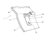
このような問題点の解決を目指して、本考案者は、図5、図6に示すブラケットの取付け構造を開発し、特開2005−170078号公報(特許文献1)として既に提案している。 In order to solve such problems, the inventor has developed a bracket mounting structure shown in FIGS. 5 and 6 and has already been proposed in Japanese Patent Application Laid-Open No. 2005-170078 (Patent Document 1).
このブラケットの取付け構造は、バイザー本体6の庇部6bの裏面に、庇部6b裏面との間にブラケット2の一端側を挿入するためのスリット8を形成する断面略門型の隆起部10aと、隆起部10aからブラケット挿入方向へ離れた位置において庇部6b裏面から突出し且つブラケット挿入方向下手側ほど高くなる傾斜面を有する係止用突起6cとを形成する一方、ブラケット2の一端側には、前記係止用突起6cと係合する切欠部(例えば、貫通孔)2dを形成し、ブラケット2の挿入に伴い、ブラケット2の一端側がブラケット2の弾性復元力に抗して前記傾斜面に乗り上げ、ブラケット2の弾性復元力によって前記切欠部2dが係止用突起6cと係合するように構成したものである。
The bracket mounting structure includes a raised
上記の構成よりなるブラケットの取付け構造は、次のような優れた利点を有する。
(1)ブラケットの一端側を、バイザー本体の庇部裏面と略門型の隆起部との間に形成されたスリットに差し込むだけで、ブラケットとバイザー本体を連結できるので、特別な工具を用いることなしに、ブラケットとバイザー本体を容易に連結でき、連結後の状態において、庇部表面にリベット頭部が露出することもない。
(2)ブラケットとバイザー本体の連結に、金属製リベットやナイロンリベットを用いないため、構成部品点数が少なくて済み、ユーザー側での連結が可能であることと相まって大幅なコストダウンを図り得る。
(3)ドアバイザーを取り外して廃棄する際、ブラケットの弾性復元力に抗して切欠部と係止用突起との係合を外すことができるので、バイザー本体とブラケットとの分別廃棄(
樹脂と金属との分別廃棄)が容易である。
The bracket mounting structure configured as described above has the following excellent advantages.
(1) Use a special tool because the bracket and visor body can be connected by simply inserting one end of the bracket into the slit formed between the rear surface of the buttock of the visor body and the substantially portal-shaped raised portion. Without being able to connect the bracket and the visor body easily, the rivet head is not exposed on the surface of the buttock in the state after the connection.
(2) Since metal rivets and nylon rivets are not used for the connection between the bracket and the visor body, the number of components can be reduced, and the connection on the user side is possible, which can greatly reduce the cost.
(3) When the door visor is removed and discarded, the notch and the locking projection can be disengaged against the elastic restoring force of the bracket, so the visor body and the bracket are separated and discarded (
Separation and disposal of resin and metal is easy.
しかしながら、試作研究の結果、図5、図6で示したブラケットの取付け構造では、ドアバイザーとしての装飾的効果を確保する上で、未だ次のような問題点があることが確認された。 However, as a result of prototype research, it was confirmed that the bracket mounting structure shown in FIGS. 5 and 6 still has the following problems in securing the decorative effect as a door visor.
即ち、図5、図6で示したブラケットの取付け構造では、ブラケット2の一端側をバイザー本体6の庇部裏面に設けた隆起部10aのスリット8に挿入し、庇部裏面の隆起部10aからブラケット挿入方向へ離れた位置に設けられた係止用突起6cに、ブラケット2の一端側に形成された切欠部2dを係合させるように構成されていた。そのため、必然的にブラケット2が挿入方向に長い形状となり、図6に示すように、ブラケット2の下端が、窓枠3に装着されるガラスランチャンネル4の下端レベルaから下方へある程度の距離Lにわたって突き出した状態とならざるを得ない。
That is, in the bracket mounting structure shown in FIG. 5 and FIG. 6, one end side of the
従って、この突き出したブラケット部分が透明な庇部6bを通して自動車の側方から見えることになり、ドアバイザーとしての装飾的効果を確保し難かったのである。即ち、バイザー本体6の庇部6bは透明な合成樹脂製であるが、窓枠3やガラスランチャンネル4は金属やゴム等によって構成された不透明な部分であるから、この不透明な部分と重なり合う位置にある庇部裏面のブラケット部分は、外部から殆ど目に付かないが、不透明な部分よりも下方に突き出したブラケット部分(ガラスランチャンネル4の下端レベルaより下のブラケット部分)は、庇部6bを通して外部からよく見えることになり、これが装飾的価値を低下させる要因となる。
Therefore, the protruding bracket portion can be seen from the side of the automobile through the
本考案は、上述した自動車用ドアバイザーにおけるブラケットの取付け構造を改良したものであって、その目的とするところは、ブラケットの一端側をバイザー本体の庇部裏面と隆起部との間に形成されたスリットに差し込むだけで、バイザー本体とブラケットとを直接に連結できるようにした構成部品点数の少ない簡単な構造であるにもかかわらず、挿入方向におけるブラケットの長さを短くすることができ、ブラケットの下端がガラスランチャンネルの下端レベルから下方へ突き出さないようにすることができるため、ブラケットが庇部を通して外部から見えることによってドアバイザーとしての装飾的効果を損なうことがないようにしたブラケットの取付け構造を提供することにある。 The present invention is an improvement of the bracket mounting structure in the above-described automobile door visor, and the object of the present invention is to form one end of the bracket between the rear surface of the buttock and the raised portion of the visor body. The bracket length in the insertion direction can be shortened despite the simple structure with a small number of component parts that allows the visor body and bracket to be directly connected by simply inserting them into the slit. It is possible to prevent the lower end of the bracket from protruding downward from the lower end level of the glass run channel, so that the decorative effect as a door visor is not impaired by the bracket being visible from the outside through the buttocks. It is to provide an installation structure.
上記の目的を達成するために、本考案が講じた技術的手段は、次の通りである。即ち、請求項1に記載の考案は、バイザー本体の庇部の裏面に、ブラケットの一端側を挿入するためのスリットを形成する隆起部を形成し、ブラケットの一端側をスリットに挿入することにより、ブラケットの一端側に設けた弾性係止片の先端が隆起部の一部と係合して抜け止めされるように構成したことを特徴としている。 In order to achieve the above object, the technical measures taken by the present invention are as follows. That is, the device according to claim 1 is formed by forming a raised portion for forming a slit for inserting one end side of the bracket on the back surface of the collar portion of the visor body, and inserting one end side of the bracket into the slit. The front end of the elastic locking piece provided on one end side of the bracket is configured to engage with a part of the raised portion and be prevented from coming off.
請求項2に記載の考案は、請求項1に記載の自動車用ドアバイザーにおけるブラケットの取付け構造であって、ブラケットにおける主板部の一端に、他端側に向けて緩やかな傾斜面を持って立上った弾性係止片を形成する一方、バイザー本体の庇部の裏面には、ブラケットの一端側を挿入するためのスリットと、スリットに挿入されたブラケットの弾性係止片の先端と係合する抜止め用係止部とを有する隆起部を形成し、弾性係止片を主板部側へ弾性変形させつつブラケットの一端側をスリットに挿入することにより、スリットを通過した弾性係止片の先端が抜止め用係止部と係合するように構成したことを特徴としてい
る。
The invention according to
請求項3に記載の考案は、請求項1又は2に記載の自動車用ドアバイザーにおけるブラケットの取付け構造であって、抜止め用係止部がスリットの下方に併設した第二のスリットによって形成されていることを特徴としている。
The invention described in claim 3 is the bracket mounting structure in the automobile door visor according to
請求項4に記載の考案は、請求項1又は2に記載の自動車用ドアバイザーにおけるブラケットの取付け構造であって、抜止め用係止部が隆起部の庇部裏面と対向する面を鈍角状に屈曲させた屈曲面によって形成されていることを特徴としている。
The invention described in claim 4 is the bracket mounting structure in the automotive door visor according to
請求項5に記載の考案は、請求項1〜4の何れかに記載の自動車用ドアバイザーにおけるブラケットの取付け構造であって、弾性係止片が主板部を斜めに折り返すことによって形成されていることを特徴としている。
請求項6に記載の考案は、請求項1〜4の何れかに記載の自動車用ドアバイザーにおけるブラケットの取付け構造であって、弾性係止片が主板部の一部を斜めに切り起こすことによって形成されていることを特徴としている。
The invention described in
The invention described in
請求項1に記載の考案によれば、ブラケットの一端側をスリットに挿入することにより、ブラケットの一端側に設けた弾性係止片の先端が隆起部の一部と係合して抜け止めされるので、ブラケットとバイザー本体を直接に連結できる。
請求項2に記載の考案によれば、弾性係止片を主板部側へ弾性変形させつつブラケットの一端側をスリットに挿入することにより、スリットを通過した弾性係止片の先端が抜止め用係止部と係合するので、ブラケットの一端側をスリットに差し込むだけで、ブラケットとバイザー本体を直接に連結できる。
According to the first aspect of the present invention, by inserting one end side of the bracket into the slit, the tip of the elastic locking piece provided on the one end side of the bracket engages with a part of the raised portion and is prevented from coming off. Therefore, the bracket and the visor body can be directly connected.
According to the second aspect of the present invention, by inserting the one end side of the bracket into the slit while elastically deforming the elastic locking piece toward the main plate portion side, the tip of the elastic locking piece that has passed through the slit is for retaining. Since it engages with the locking portion, the bracket and the visor body can be directly connected by simply inserting one end of the bracket into the slit.
殊に、請求項2に記載の考案によれば、スリットを形成する隆起部自体に抜止め用係止部を設け、スリットを通過した弾性係止片の先端が抜止め用係止部と係合するように構成したので、ブラケットの挿入方向での長さを短くすることができ、庇部を通して外部から目視し得る領域を原理的に狭くすることができる。しかも、ブラケットの挿入方向での長さを短くすることによって、ブラケットの下端をガラスランチャンネルの下端レベルから下方へ突き出さないようにすることができる。このようにすることによって、ブラケットが庇部を通して外部から見え難くなり、ドアバイザーとしての装飾的効果を損なうことがない。 In particular, according to the second aspect of the present invention, a retaining locking portion is provided on the raised portion itself forming the slit, and the tip of the elastic locking piece that has passed through the slit is engaged with the retaining locking portion. Since it was comprised so that it may match, the length in the insertion direction of a bracket can be shortened, and the area | region which can be visually recognized from the outside through a collar part can be narrowed in principle. In addition, by shortening the length in the insertion direction of the bracket, the lower end of the bracket can be prevented from protruding downward from the lower end level of the glass run channel. By doing in this way, it becomes difficult to see a bracket from the outside through a collar part, and the decorative effect as a door visor is not spoiled.
また、ドアバイザーを取り外して廃棄する際、ブラケットの弾性係止片を弾性復元力に抗して変形させることによって、弾性係止片先端と抜止め用係止部との係合を解くことが可能であるため、バイザー本体とブラケットとの分別廃棄(樹脂と金属との分別廃棄)が容易である。 Further, when the door visor is removed and discarded, the elastic locking piece of the bracket is deformed against the elastic restoring force, thereby disengaging the front end of the elastic locking piece and the retaining locking portion. Therefore, it is easy to separate and dispose of the visor body and the bracket (separate disposal of resin and metal).
請求項3に記載の考案によれば、抜止め用係止部がスリットの下方に併設した第二のスリットによって形成されており、スリットを通過した弾性係止片の先端が第二のスリットに入り込んだ状態に係合するので、ブラケットとバイザー本体の連結を強固に行うことができる。 According to the third aspect of the present invention, the retaining locking portion is formed by the second slit provided below the slit, and the tip of the elastic locking piece that has passed through the slit becomes the second slit. Since it engages in the state which entered, the connection of a bracket and a visor main body can be performed firmly.
請求項4に記載の考案によれば、抜止め用係止部が隆起部の庇部裏面と対向する面を鈍角状に屈曲させた屈曲面によって形成されているので、スリットに対するブラケットの挿入方向とは反対方向から弾性係止片と隆起部内面との隙間にマイナスドライバーを差し込むことによって、弾性係止片を弾性復元力に抗して変形させ、弾性係止片先端と抜止め用係止部との係合を解くことができ、バイザー本体とブラケットとの分離が容易である。 According to the fourth aspect of the present invention, since the retaining locking portion is formed by a bent surface obtained by bending the surface of the raised portion facing the back surface of the collar portion at an obtuse angle, the insertion direction of the bracket with respect to the slit By inserting a flathead screwdriver into the gap between the elastic locking piece and the inner surface of the raised portion from the opposite direction, the elastic locking piece is deformed against the elastic restoring force, and the elastic locking piece tip and the retaining lock The engagement with the portion can be released, and the visor body and the bracket can be easily separated.
請求項5に記載の考案によれば、弾性係止片が主板部を斜めに折り返すことによって形成されているので、ブラケットの一端側が主板部と弾性係止片の二重構造となり、ブラケットが堅牢である。
According to the invention described in
請求項6に記載の考案によれば、弾性係止片が主板部の一部を斜めに切り起こすことによって形成されているので、ブラケットの材料費が安くて済み、ブラケットの低コスト化が可能である。 According to the sixth aspect of the present invention, since the elastic locking piece is formed by obliquely raising a part of the main plate part, the material cost of the bracket can be reduced and the cost of the bracket can be reduced. It is.
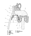
以下、本考案の実施形態を、図面を参照しながら説明する。図1、図2は、本考案に係る自動車用ドアバイザーにおけるブラケットの取付け構造の一例を示す。図において、1は自動車用ドアバイザー、2は金属製のブラケットである。3は自動車のドアに設けられた窓枠、4はガラスランチャンネル、5は窓ガラスである。 Embodiments of the present invention will be described below with reference to the drawings. 1 and 2 show an example of a bracket mounting structure in an automobile door visor according to the present invention. In the figure, 1 is an automobile door visor, and 2 is a metal bracket. 3 is a window frame provided on the door of the automobile, 4 is a glass run channel, and 5 is a window glass.
自動車用ドアバイザー1は、図2に示すように、透明な合成樹脂製のバイザー本体6のフランジ部6aを窓枠3の上辺部外側面に両面接着テープ7で接合し、バイザー本体6の庇部6bに連結されたブラケット2の上端側を窓枠3の上辺部に装着することによって取り付けられる。
As shown in FIG. 2, the automotive door visor 1 is formed by joining a
バイザー本体6は、例えばポリカーボネート等の透光性合成樹脂を素材とし、射出成形等により作製されたものであり、バイザー本体6の庇部6bは、図2に示すように、フランジ部6aから遠ざかるにつれて外側に位置するように湾曲した断面形状に形成されている。
The
ブラケット2は、例えば帯状の鋼板によって作製されたもので、図1、図2に示すように、ブラケット2における主板部2aの上端側には、窓枠3の断面形状に対応した屈曲部2bが形成されており、この屈曲部2bを、図2に示すように、窓枠3に下方から係合させることによって窓枠3の上辺部に装着される。ブラケット2における主板部2aの一端(屈曲部2bとは反対側)には、他端側(屈曲部2b側)に向けて緩やかな傾斜面を持って立上った弾性係止片2cが形成されている。図1、図2の実施形態においては、弾性係止片2cが主板部2aを斜めに折り返すことによって形成されているが、弾性係止片2cとしては、図3に示すように、主板部2aの一部を斜めに切り起こすことによって形成されたものであってもよい。
The
バイザー本体6の庇部6bの裏面には、庇部6b裏面との間にブラケット2の一端側を挿入するためのスリット8と、スリット8に挿入されたブラケット2の弾性係止片2cの先端と係合する抜止め用係止部9とを有する隆起部10が射出成形等により一体成形されている。そして、弾性係止片2cを主板部2a側へ弾性変形させつつブラケット2の一端側をスリット8に挿入することにより、スリット8を通過した弾性係止片2cの先端が弾性係止片2cの弾性復元力によって抜止め用係止部9と係合するように構成されている。
A
図示の抜止め用係止部9は、スリット8の下方にスリット8と平行に併設した第二のスリットによって形成されており、スリット8を通過した弾性係止片2cの先端が第二のスリットから成る抜止め用係止部9に入り込んだ状態に係合するので、ブラケット2とバイザー本体6の連結を強固に行うことができる。しかし、ドアバイザー1を自動車から取り外して廃棄する際には、ブラケット2の一端側を挿入方向に若干移動させた状態で、マイナスドライバーを用いて弾性係止片2cを弾性復元力に抗して変形させることによって、弾性係止片先端と抜止め用係止部9との係合を解くことが可能であり、バイザー本体6とブラケット2との分別廃棄(樹脂と金属との分別廃棄)が容易である。
The retaining locking portion 9 shown in the figure is formed by a second slit provided in parallel with the
上記の構成によれば、弾性係止片2cを主板部2a側へ弾性変形させつつブラケット2の一端側をスリット8に挿入することにより、スリット8を通過した弾性係止片2cの先端が抜止め用係止部9と係合するので、ブラケット2の一端側をスリット8に差し込むだけで、ブラケット2とバイザー本体6を直接に連結できる。
According to said structure, the front-end | tip of the
それでいて、スリット8を形成する隆起部10自体に抜止め用係止部9を設け、スリット8を通過した弾性係止片2cの先端が抜止め用係止部9と係合するように構成したので、ブラケット2の挿入方向での長さを短くすることができ、庇部6bを通して外部から目視し得る領域を原理的に狭くすることができ、図2に示すように、ブラケット2の下端をガラスランチャンネル4の下端レベルaよりも適当距離H上方に位置させることが可能である。
Nevertheless, the locking part 9 for retaining is provided on the raised
このようにすれば、ドアバイザー1を側面から見たとき、庇部6bの裏面に当接しているブラケット2の下端側部分の後方に不透明なガラスランチャンネル4が位置するので、庇部6bを通して外部からブラケット2が見えなくなり、ドアバイザーとしての装飾的効果を損なうことがない。
In this way, when the door visor 1 is viewed from the side, the opaque glass run channel 4 is located behind the lower end portion of the
また、ドアバイザーを取り外して廃棄する際、ブラケットの弾性係止片を弾性復元力に抗して変形させることによって、弾性係止片先端と抜止め用係止部との係合を解くことが可能であるため、バイザー本体とブラケットとの分別廃棄(樹脂と金属との分別廃棄)が容易である。 Further, when the door visor is removed and discarded, the elastic locking piece of the bracket is deformed against the elastic restoring force, thereby disengaging the front end of the elastic locking piece and the retaining locking portion. Therefore, it is easy to separate and dispose of the visor body and the bracket (separate disposal of resin and metal).
図4は、本考案の他の実施形態を示す。この実施形態は、抜止め用係止部9を隆起部10の内面(庇部6b裏面と対向する面)を鈍角状に屈曲させた屈曲面によって形成した点に特徴がある。
FIG. 4 shows another embodiment of the present invention. This embodiment is characterized in that the retaining locking portion 9 is formed by a bent surface in which the inner surface of the raised portion 10 (the surface facing the back surface of the
この構成によれば、弾性係止片2cを主板部2a側へ弾性変形させつつブラケット2の一端側をスリット8に挿入することにより、スリット8を通過した弾性係止片2cの先端が弾性係止片2cの弾性復元力によって屈曲面から成る抜止め用係止部9と係合して、抜け止め状態に固定されるが、抜止め用係止部9が鈍角状に屈曲させた屈曲面によって形成されているので、仮想線で示すように、下方からマイナスドライバー11を差し込むだけで弾性係止片2cを弾性復元力に抗して変形させることができ、屈曲面(抜止め用係止部9)と抜止め用係止部9先端との係合を解くことができる。
According to this configuration, by inserting one end of the
従って、図2に示した実施形態よりも、バイザー本体6とブラケット2との分別廃棄(樹脂と金属との分別廃棄)が容易である。その他の構成、作用は、先の実施形態と同じであるため、説明を省略する。
Therefore, it is easier to separate and discard the
尚、図4では、ブラケット2として、図3に示すように、主板部2aの一部を斜めに切り起こして弾性係止片2cを形成したものを用いているが、図1、図2に示したように、主板部2aを斜めに折り返すことによって弾性係止片2cを形成したタイプのブラケット2を用いてもよい。
In FIG. 4, as the
1 ドアバイザー
2 ブラケット
2a 主板部
2b 屈曲部
2c 弾性係止片
3 窓枠
4 ガラスランチャンネル
5 窓ガラス
6 バイザー本体
6a フランジ部
6b 庇部
7 両面接着テープ
8 スリット
9 抜止め用係止部(第二のスリット、屈曲面)
10 隆起部
11 マイナスドライバー
DESCRIPTION OF SYMBOLS 1
10 Raised
Claims (6)
Priority Applications (1)
| Application Number | Priority Date | Filing Date | Title |
|---|---|---|---|
| JP2008002682U JP3143114U (en) | 2008-04-25 | 2008-04-25 | Bracket mounting structure for automotive door visor |
Applications Claiming Priority (1)
| Application Number | Priority Date | Filing Date | Title |
|---|---|---|---|
| JP2008002682U JP3143114U (en) | 2008-04-25 | 2008-04-25 | Bracket mounting structure for automotive door visor |
Publications (1)
| Publication Number | Publication Date |
|---|---|
| JP3143114U true JP3143114U (en) | 2008-07-10 |
Family
ID=43293076
Family Applications (1)
| Application Number | Title | Priority Date | Filing Date |
|---|---|---|---|
| JP2008002682U Expired - Fee Related JP3143114U (en) | 2008-04-25 | 2008-04-25 | Bracket mounting structure for automotive door visor |
Country Status (1)
| Country | Link |
|---|---|
| JP (1) | JP3143114U (en) |
Cited By (2)
| Publication number | Priority date | Publication date | Assignee | Title |
|---|---|---|---|---|
| JP2010042691A (en) * | 2008-08-08 | 2010-02-25 | Tamura Plastic Mfg Co Ltd | Visor for automobile and its mounting structure |
| JP2015105068A (en) * | 2013-12-02 | 2015-06-08 | 田村プラスチック製品株式会社 | Automobile exterior product, and fitting structure of automobile exterior product |
-
2008
- 2008-04-25 JP JP2008002682U patent/JP3143114U/en not_active Expired - Fee Related
Cited By (2)
| Publication number | Priority date | Publication date | Assignee | Title |
|---|---|---|---|---|
| JP2010042691A (en) * | 2008-08-08 | 2010-02-25 | Tamura Plastic Mfg Co Ltd | Visor for automobile and its mounting structure |
| JP2015105068A (en) * | 2013-12-02 | 2015-06-08 | 田村プラスチック製品株式会社 | Automobile exterior product, and fitting structure of automobile exterior product |
Similar Documents
| Publication | Publication Date | Title |
|---|---|---|
| KR101752265B1 (en) | A cramping fastener device | |
| KR20070114039A (en) | Two-piece clip | |
| JP2007211918A (en) | Component mounting device | |
| CN110466446B (en) | Interior trim cover installation component | |
| CN106608166B (en) | Automobile door structure | |
| US10293670B2 (en) | Vehicle molding | |
| JP3143114U (en) | Bracket mounting structure for automotive door visor | |
| JP5083689B2 (en) | Bracket mounting structure for automotive door visor | |
| JP5898941B2 (en) | Mounting structure for decoration malls for automobile exterior parts | |
| JP2014228031A (en) | Mounting structure for mounting member | |
| JP4373197B2 (en) | Bracket mounting structure for automotive door visor | |
| JP4620692B2 (en) | Bumper positioning structure | |
| JP2006192975A (en) | Front fender mounting part structure of cover member | |
| JP4511769B2 (en) | Car door visor mounting structure | |
| JP5315541B2 (en) | Mounting structure for vehicle instrument panel | |
| JP4952989B2 (en) | Cowl top garnish | |
| JP6033623B2 (en) | Bumper mounting structure of vehicle | |
| JP5461257B2 (en) | Car door structure | |
| JP2013103687A (en) | Vehicle door trim mounting structure | |
| JP6027526B2 (en) | Vehicle visor | |
| JP2604073Y2 (en) | Automotive door window inner seal mounting structure | |
| JP2013256194A (en) | Belt molding | |
| JP5041818B2 (en) | Automotive visor mounting bracket | |
| JP3631055B2 (en) | Power window finisher mounting structure for door armrests for automobiles | |
| JP2007253747A (en) | Connecting device of part for automobile |
Legal Events
| Date | Code | Title | Description |
|---|---|---|---|
| R150 | Certificate of patent or registration of utility model |
Free format text: JAPANESE INTERMEDIATE CODE: R150 |
|
| FPAY | Renewal fee payment (event date is renewal date of database) |
Free format text: PAYMENT UNTIL: 20110618 Year of fee payment: 3 |
|
| FPAY | Renewal fee payment (event date is renewal date of database) |
Free format text: PAYMENT UNTIL: 20110618 Year of fee payment: 3 |
|
| FPAY | Renewal fee payment (event date is renewal date of database) |
Free format text: PAYMENT UNTIL: 20120618 Year of fee payment: 4 |
|
| FPAY | Renewal fee payment (event date is renewal date of database) |
Free format text: PAYMENT UNTIL: 20120618 Year of fee payment: 4 |
|
| FPAY | Renewal fee payment (event date is renewal date of database) |
Free format text: PAYMENT UNTIL: 20130618 Year of fee payment: 5 |
|
| R250 | Receipt of annual fees |
Free format text: JAPANESE INTERMEDIATE CODE: R250 |
|
| LAPS | Cancellation because of no payment of annual fees |