JP3137904U - Blade sharpener - Google Patents

Blade sharpener Download PDF

Info

Publication number
JP3137904U
JP3137904U JP2007007505U JP2007007505U JP3137904U JP 3137904 U JP3137904 U JP 3137904U JP 2007007505 U JP2007007505 U JP 2007007505U JP 2007007505 U JP2007007505 U JP 2007007505U JP 3137904 U JP3137904 U JP 3137904U
Authority
JP
Japan
Prior art keywords
blade
screw member
support base
male screw
sharpening tool
Prior art date
Legal status (The legal status is an assumption and is not a legal conclusion. Google has not performed a legal analysis and makes no representation as to the accuracy of the status listed.)
Expired - Fee Related
Application number
JP2007007505U
Other languages
Japanese (ja)
Inventor
正静 平出
Original Assignee
正静 平出
Priority date (The priority date is an assumption and is not a legal conclusion. Google has not performed a legal analysis and makes no representation as to the accuracy of the date listed.)
Filing date
Publication date
Application filed by 正静 平出 filed Critical 正静 平出
Priority to JP2007007505U priority Critical patent/JP3137904U/en
Application granted granted Critical
Publication of JP3137904U publication Critical patent/JP3137904U/en
Anticipated expiration legal-status Critical
Expired - Fee Related legal-status Critical Current

Links

Images

Abstract

【課題】移動に伴う方向性を確保すると共に、抵抗を低減し、しかも刃物と刃物の研ぎ具との位置決めを正確に行うことができるようにする。
【解決手段】砥面8に刃体3が接触可能となるように砥面8を移動自在な刃物の支持台5を設け、砥面8を転動するローラー6を支持台5に一体に設ける。刃物と支持台5とは螺子9を介して着脱可能に設ける。研ぎ具4と砥面8との接触は、面接触よりもはるかに面積が小さく、移動に伴う摩擦を低減して研ぎ作業を行うことができる。さらに、刃物に対する支持台5の位置は螺子9によって正確に行われ、しかもその脱着は比較的容易である。
【選択図】図1
To ensure the directionality associated with movement, to reduce resistance, and to accurately position the blade and the sharpening tool of the blade.
A blade support base 5 is provided so that the blade body 3 can come into contact with the abrasive surface 8, and a roller 6 that rolls the abrasive surface 8 is provided integrally with the support base 5. . The blade and the support base 5 are detachably provided via screws 9. The contact between the sharpening tool 4 and the abrasive surface 8 has a much smaller area than the surface contact, and the sharpening work can be performed while reducing the friction caused by the movement. Furthermore, the position of the support base 5 with respect to the blade is accurately determined by the screw 9, and its attachment / detachment is relatively easy.
[Selection] Figure 1

Description

本考案は、鑿、鉋、彫刻刀、ナイフなどの刃体の付いている刃物の研ぎ具に関するものである。   The present invention relates to a sharpening tool for blades having blades such as a spear, a scissors, a carving sword, and a knife.

従来の刃物用素材である生地は、不純物が多い鋼がほとんどであり、このため刃体そのものが軟らかく、刃の研磨がやりやすいものであった。しかしながら、現在の鋼は純度が高いので硬く、素人はそのために研磨がやりづらくなっている。これは刃体と砥石の表面とを平行にするのが難しく、素人、さらにはプロであっても砥石の表面を刃体で削ってしまい砥石の中央部に窪みができてしまった。   Conventional dough, which is a material for blades, is mostly steel with a large amount of impurities. Therefore, the blade itself is soft and the blade can be easily polished. However, the current steel is hard because of its high purity, which makes it difficult for amateurs to polish. This makes it difficult to make the blade body and the surface of the grindstone parallel to each other, and even amateurs and professionals have shaved the surface of the grindstone with the blade body, resulting in a depression at the center of the grindstone.

従来、この種のものとして平滑平面に整えられた砥面をもつ砥石とその砥面と平行な面内における移動自在な滑走台とを備え、滑走台は、柄付き刃物をその前端にて研ぎおろしをすべき表刃が全面又は少なくとも母線にて砥面と接する姿勢となるべき、長手方向の傾斜角度及び軸心のまわりの回転角度の調節とその抑止拘束を可能として保持する刃物受けを有するものであって、柄付き刃物の握りの上面を作業者の指先により刃物受け上に抑止して保持しつつ滑走台を砥面平行な面上にて平面接触させて摺動させることにより刃を研ぐことができるというものである(例えば、特許文献1)。
特開2002−46043号公報
Conventionally, this kind of grindstone has a grindstone with a smooth grinding surface and a slide that is movable in a plane parallel to the grindstone. The slide is sharpened at the front edge with a handle. There is a blade holder that holds the front blade to be lowered in a posture that makes contact with the grinding surface on the entire surface or at least on the generatrix, and enables adjustment of the inclination angle in the longitudinal direction and the rotation angle around the axis and restraining restraint thereof. The blade is moved by sliding the slide table in plane contact with the surface parallel to the grinding surface while holding the upper surface of the handle of the blade with a handle on the blade receiver with the fingertip of the operator. It can be sharpened (for example, Patent Document 1).
JP 2002-46043 A

しかし、従来技術においては、柄付き刃物を保持した滑走台が砥面平行な面上にて摺動する状態は比較接触面積の大きい平面接触によるものであったので、移動方向を定めにくく、また柄付き刃物を動かすときには、刃物の柄を下方に押圧しながら前後に移動する必要があるので、平面接触ではその接触抵抗は大きくなる傾向があり、この結果いっそう刃物を移動しにくくなるという問題が生ずる。   However, in the prior art, the state in which the slide holding the blade with the handle slides on the surface parallel to the grinding surface is due to flat contact with a large comparative contact area, so it is difficult to determine the moving direction. When moving a blade with a handle, it is necessary to move back and forth while pressing the handle of the blade downward, so that the contact resistance tends to increase in flat contact, and as a result, there is a problem that the blade is more difficult to move. Arise.

解決しようとする問題点は、刃物を保持して砥石またはその砥面と平行な面内における移動自在で刃物を保持する移動台における移動に伴う方向性を確保すると共に、抵抗を低減し、しかも刃物と刃物の研ぎ具との位置決めを正確に行うことができるようにする点である。   The problem to be solved is to secure the directionality associated with the movement of the moving table that holds the cutter and is movable in the grindstone or the plane parallel to the grinding surface and holds the cutter, and reduces the resistance. The point is that the blade and the sharpening tool of the blade can be accurately positioned.

請求項1の考案は、刃物の刃体が砥面に接触可能となるように前記砥面又はこの砥面と平行な面内を移動自在な刃物の支持台を設けた刃物の研ぎ具において、螺子を介して前記刃物と着脱可能な前記支持台に、前記砥面又はこの砥面と平行な面を転動する円形のローラーを設けたことを特徴とする刃物の研ぎ具である。   The invention of claim 1 is a sharpening tool for a blade provided with a support for the blade that is movable on the abrasive surface or in a plane parallel to the abrasive surface so that the blade body of the blade can come into contact with the abrasive surface. A sharpening tool for a blade, characterized in that a circular roller that rolls on the grinding surface or a surface parallel to the grinding surface is provided on the support base that is detachable from the blade via a screw.

請求項2の考案においては、前記螺子は、前記支持台に設けた雄螺子部材と、前記刃物に設けられ前記雄螺子部材が螺着可能な雌螺子とからなることを特徴とする請求項1記載の刃物の研ぎ具である。   According to a second aspect of the present invention, the screw is composed of a male screw member provided on the support base and a female screw provided on the blade to which the male screw member can be screwed. It is a sharpening tool for the described blade.

請求項3の考案においては、前記螺子は、前記刃物に設けた雄螺子部材と、前記支持台に設けられ前記雄螺子部材が螺着可能な雌螺子とからなることを特徴とする請求項1記載の刃物の研ぎ具である。   The invention according to claim 3 is characterized in that the screw is composed of a male screw member provided on the blade and a female screw provided on the support base to which the male screw member can be screwed. It is a sharpening tool for the described blade.

請求項4の考案においては、前記螺子は、前記支持台に設けた雄螺子部材と、前記刃物に設けられた孔を通った前記雄螺子部材に螺着可能な雌螺子部材とからなることを特徴とする請求項1記載の刃物の研ぎ具である。   According to a fourth aspect of the present invention, the screw includes a male screw member provided on the support base and a female screw member that can be screwed to the male screw member that passes through a hole provided in the blade. The sharpening tool for a blade according to claim 1, wherein the sharpening tool is provided.

請求項5の考案においては、前記螺子は、前記刃物に設けた雄螺子部材と、前記支持台に設けられた孔を通った前記雄螺子部材に螺着可能な雌螺子部材とからなることを特徴とする請求項1記載の刃物の研ぎ具である。   According to a fifth aspect of the present invention, the screw includes a male screw member provided on the blade and a female screw member that can be screwed to the male screw member that has passed through a hole provided in the support base. The sharpening tool for a blade according to claim 1, wherein the sharpening tool is provided.

請求項6の考案においては、前記ローラーは前記支持台の左右両側に設けられており、これら左右のローラーの間に前記雄螺子部材の先端が上向きに設けられることを特徴とする請求項2又は4記載の刃物の研ぎ具である。   The invention according to claim 6 is characterized in that the rollers are provided on both left and right sides of the support base, and the tip of the male screw member is provided upward between the left and right rollers. 4. A sharpening tool for blades according to 4.

請求項7の考案においては、前記ローラーは前記支持台の左右両側に設けられており、これら左右のローラーの間に前記雌螺子の先端が下向きに設けられることを特徴とする請求項3記載の刃物の研ぎ具である。   The invention according to claim 7 is characterized in that the rollers are provided on both the left and right sides of the support base, and the tip of the female screw is provided downward between the left and right rollers. A sharpening tool for blades.

請求項8の考案においては、前記ローラーは前記支持台の左右両側に設けられており、これら左右のローラーの間に前記孔が上下方向に設けられることを特徴とする請求項5記載の刃物の研ぎ具である。   In the invention of claim 8, the rollers are provided on both the left and right sides of the support base, and the hole is provided in the vertical direction between the left and right rollers. It is a sharpening tool.

請求項9の考案においては、前記左右両側のローラーの中心軸線は同一直線上に設けられていることを特徴とする請求項6〜8のいずれか1項に記載の刃物の研ぎ具である。   In the invention of claim 9, the sharpening tool for blades according to any one of claims 6 to 8, wherein the central axes of the left and right rollers are provided on the same straight line.

請求項1の考案によれば、研ぎ具と砥面又はこの砥面と平行な面との接触面積はローラーにより小さくなるので、移動に伴う摩擦を低減して研ぎ作業を行うことができると共に、螺子を介して刃物と支持台を着脱可能に固定することで両者間の位置決め固定を簡単に行うことができる。   According to the invention of claim 1, since the contact area between the sharpening tool and the grinding surface or a surface parallel to the grinding surface is reduced by the roller, it is possible to reduce the friction associated with the movement and perform the grinding work. By fixing the blade and the support base detachably through the screw, the positioning and fixing between them can be easily performed.

請求項2の考案によれば、支持台に設けた雄螺子部材を刃物に設けられた雌螺子に螺着して研ぎ具に刃物を装着することができる。   According to the invention of claim 2, it is possible to attach the blade to the sharpening tool by screwing the male screw member provided on the support base to the female screw provided on the blade.

請求項3の考案によれば、刃物に設けた雄螺子部材を支持台に設けた雌螺子に螺着して研ぎ具に刃物を装着することができる。   According to the invention of claim 3, it is possible to attach the blade to the sharpening tool by screwing the male screw member provided on the blade to the female screw provided on the support base.

請求項4の考案によれば、支持台に設けた雄螺子部材を刃物の孔に通し雌螺子部材を螺着して研ぎ具に刃物を装着することができる。   According to the fourth aspect of the present invention, it is possible to attach the blade to the sharpening tool by passing the male screw member provided on the support base through the hole of the blade and screwing the female screw member.

請求項5の考案によれば、刃物に設けた雄螺子部材を支持台の孔に通し雌螺子部材を螺着して研ぎ具に刃物を装着することができる。   According to the fifth aspect of the present invention, the male screw member provided on the blade can be passed through the hole of the support base and the female screw member can be screwed to attach the blade to the sharpening tool.

請求項6〜8の考案によれば、左右のローラーの間に刃物が支持されるので安定性を向上できる。   According to the inventions of claims 6 to 8, since the blade is supported between the left and right rollers, the stability can be improved.

請求項9の考案によれば、左右一対のローラーの向きを一定方向とするので、支持台に保持した刃体はローラーの向きにしたがって左右にぶれることなく一定方向に移動して研ぎ作業を行うことができる。   According to the ninth aspect of the present invention, the direction of the pair of left and right rollers is set to a fixed direction, so that the blade body held on the support base moves in a fixed direction according to the direction of the roller and moves in a fixed direction to perform the sharpening work. be able to.

本考案における好適な実施の形態について、添付図面を参照して説明する。尚、以下に説明する実施の形態は、実用新案登録請求の範囲に記載された本考案の内容を限定するものではない。また、以下に説明される構成の全てが、本考案の必須要件であるとは限らない。   Preferred embodiments of the present invention will be described with reference to the accompanying drawings. The embodiment described below does not limit the contents of the present invention described in the claims of the utility model registration. In addition, all the configurations described below are not necessarily essential requirements of the present invention.

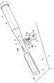
図1〜2は実施例1を示しており、鑿たる刃物1は、木製の柄2の先端に平刃状の刃体3が前方へ向けて突設している。刃物1の研ぎ具4は、刃物1を支持して保持するための支持台5が設けられる。支持台5の左右にはローラー6を一体的に設けている。これらローラー6は、外周面6Aの径が同一であり後述する第1の中心軸線を中心としたとき外側に配置される円形であって転がして使用するものであって、実施例では合成樹脂製の円板状である。尚、このローラー6は、円筒形や車輪のようにスポークやホイールを介して取付けるリング状であってもよい。そして、砥石7の砥面8に刃体3の先端3Aが接触可能となるように、ローラー6は、砥面8又はこの砥面8と平行な面内を移動するために、砥面8又はこの砥面8と平行な面に外周面6Aが接地して転動するものである。   1 and 2 show the first embodiment, in which a scissors cutting tool 1 has a flat blade-like blade body 3 projecting forward from the tip of a wooden handle 2. The sharpening tool 4 for the blade 1 is provided with a support base 5 for supporting and holding the blade 1. Rollers 6 are integrally provided on the left and right sides of the support base 5. These rollers 6 have the same diameter of the outer peripheral surface 6A and are circularly arranged on the outer side when the first central axis described later is used as the center, and are used by rolling. It is a disk shape. The roller 6 may have a ring shape that is attached via a spoke or a wheel like a cylinder or a wheel. Then, the roller 6 moves in the grinding surface 8 or in a plane parallel to the grinding surface 8 so that the tip 3A of the blade body 3 can come into contact with the grinding surface 8 of the grinding wheel 7. The outer peripheral surface 6 </ b> A contacts the surface parallel to the abrasive surface 8 and rolls.

そして支持台5と刃物1との間には、該支持台5の前後方向に刃物1を着脱自在に固定する固定手段としての螺子9が設けられる。この螺子9は支持台5側に設けられる雄螺子部材10と、刃物1側、具体的には首等と称せられる基端3B側に設けられて雄螺子部材10が螺着可能な雌螺子11によって形成される。   And between the support stand 5 and the cutter 1, the screw | thread 9 as a fixing means which fixes the cutter 1 in the front-back direction of this support stand 5 so that attachment or detachment is possible is provided. This screw 9 is provided with a male screw member 10 provided on the support base 5 side, and a female screw 11 provided on the blade 1 side, specifically, on the base end 3B side referred to as a neck or the like, to which the male screw member 10 can be screwed. Formed by.

さらに、前記左右一対のローラー6の中心軸は、進行方向に対向するように配置される同一直線状の第1の中心軸線12上に配置され、そしてこの左右一対のローラー6の間に雄螺子部材10が設けられる。この雄螺子部材10の基端10Bは支持台5に固定されると共に、先端10Aは上向きに設けられている。また、雌螺子11は刃物1の下面に下向きに設けられるものであって、雌螺子11の長手方向は刃物1の長手方向中心軸線13に対して直交するようになっている。この雌螺子11は実施例では1箇所であるが長手方向中心軸線13に沿って複数箇所設けておき、そのうちのいずれかに雄螺子部材10を螺着できるようにしておいてよい。尚、図中14は雄螺子部材10に螺着するナット等の緩み止め雌螺子部材である。   Further, the central axes of the pair of left and right rollers 6 are arranged on the same first linear axis 12 arranged so as to face the traveling direction, and a male screw is interposed between the pair of left and right rollers 6. A member 10 is provided. The base end 10B of the male screw member 10 is fixed to the support base 5, and the tip 10A is provided upward. The female screw 11 is provided downward on the lower surface of the blade 1, and the longitudinal direction of the female screw 11 is orthogonal to the longitudinal central axis 13 of the blade 1. Although the female screw 11 is provided at one location in the embodiment, a plurality of locations may be provided along the central axis 13 in the longitudinal direction so that the male screw member 10 can be screwed into any one of them. In the figure, reference numeral 14 denotes a female screw member for preventing loosening such as a nut screwed to the male screw member 10.

次に前記構成についてその作用を説明する。刃物1を研ぎ具4に取付けるには、まず先端10Aを雌螺子11に挿入するように雄螺子部材10を螺入させる。この雄螺子部材10の螺入長さを調整することで刃体3の先端3Aにおける刃先角度を調節できる。この雄螺子部材10の螺入においては、雄螺子部材10を回転中心として支持台5を回動することで行われる。そして、所定長さ雄螺子部材10を螺入させた後に、予め雄螺子部材10に取り付けていた緩み止め雌螺子部材14を回動して基端3Bに当接して緩み止めを行う。   Next, the operation of the above configuration will be described. In order to attach the blade 1 to the sharpening tool 4, first, the male screw member 10 is screwed so that the tip 10 </ b> A is inserted into the female screw 11. By adjusting the screwing length of the male screw member 10, the blade edge angle at the tip 3A of the blade body 3 can be adjusted. The screwing of the male screw member 10 is performed by rotating the support base 5 around the male screw member 10 as a rotation center. Then, after the male screw member 10 having a predetermined length is screwed in, the loosening-preventing female screw member 14 previously attached to the male screw member 10 is rotated and brought into contact with the base end 3B to prevent the loosening.

次に刃体3を砥石7の砥面8に接触させて、柄2に下向きの力を加えて、支持台5を砥面8に対して前後に移動する。この際支持台5、ひいては刃物1は左右一対のローラー6が砥面8上を転動することにより移動しながら、刃体3の砥面8による研ぎ作業を行うことができる。   Next, the blade body 3 is brought into contact with the grinding surface 8 of the grindstone 7, a downward force is applied to the handle 2, and the support 5 is moved back and forth with respect to the grinding surface 8. At this time, the support table 5 and the blade 1 can be sharpened by the grinding surface 8 of the blade body 3 while the pair of left and right rollers 6 move by rolling on the grinding surface 8.

以上のように、前記実施例では請求項1に対応して、砥面8に刃体3が接触可能となるように砥面8を移動自在な刃物1の支持台5を設け、砥面8を転動するローラー6を支持台5に一体に設けたことにより、研ぎ具4と砥面8との接触は、面接触よりもはるかに面積が小さくなる線接触状や点接触状に近くなるので、移動に伴う摩擦を低減して研ぎ作業を行うことができる。さらに、刃物1と支持台5とは螺子9を介して着脱可能としたので、刃物1に対する支持台5の位置は螺子9によって正確に行われ、しかもその脱着は比較的容易である。   As described above, in the embodiment, corresponding to claim 1, the support base 5 for the cutter 1 that can move the abrasive surface 8 is provided so that the blade body 3 can come into contact with the abrasive surface 8. Since the roller 6 that rolls is integrally provided on the support base 5, the contact between the sharpening tool 4 and the grinding surface 8 becomes close to a line contact or a point contact with a much smaller area than the surface contact. Therefore, it is possible to reduce the friction accompanying the movement and perform the sharpening work. Furthermore, since the blade 1 and the support base 5 are detachable via the screw 9, the position of the support base 5 with respect to the blade 1 is accurately performed by the screw 9, and the attachment / detachment thereof is relatively easy.

また、前記実施例では請求項2に対応して、前記螺子9は、支持台5に設けた雄螺子部材10と、刃物3に設けられ雄螺子部材10が螺着可能な雌螺子11とからなるので、雄螺子部材10を雌螺子11に螺着するだけで刃物1に対する支持台5の位置を正確に設定でき、しかもその脱着も容易である。   In the embodiment, corresponding to claim 2, the screw 9 includes a male screw member 10 provided on the support base 5 and a female screw 11 provided on the blade 3 and to which the male screw member 10 can be screwed. Therefore, the position of the support base 5 with respect to the blade 1 can be accurately set only by screwing the male screw member 10 to the female screw 11, and the attachment / detachment thereof is easy.

さらに、請求項6に対応してローラー6は支持台5の左右両側に設けられており、これら左右のローラー6の間に雄螺子部材10の先端10Aが上向きに設けられることにより、ローラー6間の幅を支持台5の幅より大きくできることで、ローラー6間の幅が支持台5の幅程度に大きくでき移動するときの左右のぶれなどが少なくなり安定性を向上することができる。また上向きの雄螺子部材10により支持台5の上方に刃物1を配置でき、刃物1を押し付けしやすくなる。   Further, the rollers 6 are provided on the left and right sides of the support base 5 in correspondence with the sixth aspect, and the tip 10A of the male screw member 10 is provided between the left and right rollers 6 so that the gap between the rollers 6 is increased. Can be made larger than the width of the support base 5, the width between the rollers 6 can be made as large as the width of the support base 5, and the left and right shakes when moving can be reduced, and the stability can be improved. Further, the blade 1 can be disposed above the support 5 by the upward male screw member 10, and the blade 1 can be easily pressed.

しかも、請求項9に対応して右両側のローラー6の中心軸線は第1の中心軸線12に同一直線上に設けられているので、ローラー6は同じ方向を向いて支持台5、ひいては刃体3はローラー6の向きにしたがって左右にぶれることなく一定方向に移動して研ぎ作業を行うことができる。   In addition, since the central axes of the rollers 6 on both right sides are provided on the same straight line as the first central axis 12 in correspondence with the ninth aspect, the rollers 6 face the same direction so that the support base 5 and eventually the blade body 3 can move in a certain direction according to the direction of the roller 6 without moving from side to side and perform the sharpening operation.

以下に、他の実施例を説明する。尚、前記実施例1と同一部分には同一符号を付し、その詳細な説明を省略する。   Other embodiments will be described below. In addition, the same code | symbol is attached | subjected to the same part as the said Example 1, and the detailed description is abbreviate | omitted.

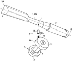
図3〜4は実施例2を示しており、実施例2においては、鉋に使用される鉋刃である刃物1´の長手方向中心軸線13上に、該中心軸線13と直交して雌螺子11が設けられている。この雌螺子11は刃物1´の下面と上面とを結んで貫通して設けられている。   3 to 4 show a second embodiment. In the second embodiment, the female screw is perpendicular to the central axis 13 on the longitudinal central axis 13 of the cutter 1 'that is a scissors used for the scissors. 11 is provided. The female screw 11 is provided through and connecting the lower surface and the upper surface of the blade 1 '.

したがって、実施例2においても、先端10Aを雌螺子11に挿入するように雄螺子部材10を螺入させて刃物1を研ぎ具4に取付ける。そして刃体3´を砥石7の砥面8に接触させて、柄2に下向きの力を加えて、支持台5をローラー6を介して砥面8又はこの砥面8と平行な台板などの面内8Aに対して前後に移動し、先端3Aを研ぐものである。   Therefore, also in the second embodiment, the blade 1 is attached to the sharpening tool 4 by screwing the male screw member 10 so that the tip 10A is inserted into the female screw 11. Then, the blade body 3 ′ is brought into contact with the grinding surface 8 of the grindstone 7, a downward force is applied to the handle 2, and the support base 5 is passed through the roller 6 with the grinding surface 8 or a base plate parallel to the grinding surface 8. It moves back and forth with respect to the in-plane 8A and sharpens the tip 3A.

このような実施例2においても、実施例1と同様に刃物1´に対する支持台5の位置は螺子9によって正確に行われ、しかもその脱着は比較的容易である。   Also in the second embodiment, as in the first embodiment, the position of the support base 5 with respect to the blade 1 'is accurately performed by the screw 9, and the attachment / detachment thereof is relatively easy.

図5は実施例3を示しており、刃物1の基端3B側に雄螺子部材10´が設けられると共に、支持台5に雄螺子部材10´の先端10Aが螺着する雌螺子11´が設けられている。雌螺子11´の先端11Aは上面から下向きに設けられている。尚、刃体3に設けられる雄螺子部材10´は、実施例では一体に設けたものを示したが、雄螺子部材10´を一体に設けたアタッチメント(図示せず)を刃物1に着脱自在に取り付けた状態で雄螺子部材10´を雌螺子11´に螺着して刃体3を研ぐようにしてもよい。   FIG. 5 shows a third embodiment, in which a male screw member 10 ′ is provided on the base end 3 B side of the blade 1, and a female screw 11 ′ on which the tip 10 A of the male screw member 10 ′ is screwed to the support base 5. Is provided. The tip 11A of the female screw 11 'is provided downward from the upper surface. In the embodiment, the male screw member 10 ′ provided on the blade body 3 is integrally provided, but an attachment (not shown) integrally provided with the male screw member 10 ′ is detachable from the blade 1. The blade member 3 may be sharpened by screwing the male screw member 10 ′ to the female screw 11 ′ in a state where the blade body 3 is attached.

従って、実施例3においても、先端10Aを雌螺子11´に挿入するように雄螺子部材10´を螺入させて刃物1を研ぎ具4に取付ける。そして刃体3´を砥石7の砥面8に接触させて、柄2に下向きの力を加えて、支持台5を、ローラー6を介して砥面8に対して前後に移動し、先端3Aを研ぐものである。   Accordingly, also in the third embodiment, the blade 1 is attached to the sharpening tool 4 by screwing the male screw member 10 'so that the tip 10A is inserted into the female screw 11'. Then, the blade body 3 ′ is brought into contact with the grinding surface 8 of the grindstone 7, a downward force is applied to the handle 2, the support 5 is moved back and forth with respect to the grinding surface 8 via the roller 6, and the tip 3 A To sharpen.

以上のように、前記実施例では請求項3に対応して、刃物1に設けた雄螺子部材10´と、支持台5に設けられ雄螺子部材10´が螺着可能な雌螺子11´とを備え、刃物1に対する支持台5の位置は螺子9´によって正確に行われ、しかもその脱着は比較的容易である。   As described above, in the embodiment, corresponding to claim 3, the male screw member 10 'provided on the blade 1 and the female screw 11' provided on the support base 5 to which the male screw member 10 'can be screwed. The position of the support base 5 with respect to the blade 1 is accurately determined by the screw 9 ', and the attachment / detachment thereof is relatively easy.

また、請求項7に対応してローラー6は支持台5の左右両側に設けられており、これら左右のローラー6の間に雌螺子11´の先端11Aが下向きに設けられることで、ローラー6間の幅が支持台5の幅程度に大きくでき移動するときの左右のぶれなどが少なくなり安定性を向上することができる。また下向きの雌螺子11´により支持台5の上方に刃物1を配置でき、刃物1を押し付けしやすくなる。   Corresponding to claim 7, the rollers 6 are provided on both the left and right sides of the support base 5, and the tip 11 </ b> A of the female screw 11 ′ is provided downward between the left and right rollers 6, so Can be made as large as the width of the support 5, and left and right shakes when moving can be reduced and stability can be improved. Further, the blade 1 can be disposed above the support 5 by the downward female screw 11 ', and the blade 1 can be easily pressed.

図6〜7は実施例4を示しており、螺子9は、支持台5に設けた雄螺子部材10と、刃物1に設けられた孔21を通った雄螺子部材10に螺着可能な蝶ナットや六角ナット等の雌螺子部材22とからなり、ローラー6は支持台5の左右両側に設けられており、これら左右のローラー6は第1の中心軸線12上に配置されている。また左右のローラー6の内側に雄螺子部材10が突設している。   FIGS. 6 to 7 show a fourth embodiment. The screw 9 is a butterfly that can be screwed to the male screw member 10 provided on the support base 5 and the male screw member 10 that has passed through the hole 21 provided on the blade 1. The roller 6 is provided on both the left and right sides of the support base 5, and the left and right rollers 6 are disposed on the first central axis 12. A male screw member 10 projects from the left and right rollers 6.

したがって、実施例4においては、請求項4に対応して先端10Aを孔21に挿入するようにして雄螺子部材10を下から上へ貫通し、そして刃体3の上面より突出した先端10Aに雌螺子部材22を螺着させて固定する。この際、緩み止め雌螺子部材14によって高さ調整を行って刃物1を研ぎ具4に取付ける。そして刃体3´を砥石7の砥面8に接触させて下向きの力を加えて、支持台5を、ローラー6を介して砥面8に対して前後に移動し、先端3Aを研ぐものである。   Accordingly, in the fourth embodiment, the male screw member 10 is penetrated from the bottom to the top so that the tip 10A is inserted into the hole 21 in accordance with claim 4, and the tip 10A protruding from the upper surface of the blade body 3 is formed. The female screw member 22 is screwed and fixed. At this time, the blade 1 is attached to the sharpening tool 4 by adjusting the height with the female screw member 14 for preventing loosening. Then, the blade body 3 ′ is brought into contact with the grinding surface 8 of the grindstone 7 to apply a downward force, the support 5 is moved back and forth with respect to the grinding surface 8 via the roller 6, and the tip 3 A is sharpened. is there.

以上のように前記実施例では請求項4に対応して、支持台5に設けた雄螺子部材10と、刃物1´に設けられた孔21を通った雄螺子部材10に螺着可能な雌螺子部材22とからなることにより、雄螺子部材10に雌螺子部材22を螺着するだけで刃物1に対する支持台5の位置を正確に設定でき、しかもその脱着も容易である。   As described above, according to the fourth embodiment, the female screw member 10 provided in the support base 5 and the female screw member 10 that can be screwed into the male screw member 10 that has passed through the hole 21 provided in the blade 1 ′ are provided in the embodiment. By including the screw member 22, the position of the support base 5 with respect to the blade 1 can be accurately set only by screwing the female screw member 22 to the male screw member 10, and the attachment and removal thereof is easy.

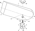
図8は実施例5を示しており、螺子9は、刃体3に設けた雄螺子部材10´と、支持台5に設けられた孔23を通った雄螺子部材10に螺着可能な蝶ナットや六角ナット等の雌螺子部材22とからなり、ローラー6は支持台5の左右両側に設けられており、これら左右のローラー6の中心軸は第1の中心軸線12上に配置されている。   FIG. 8 shows a fifth embodiment. A screw 9 is a butterfly that can be screwed to a male screw member 10 ′ provided in the blade body 3 and a male screw member 10 that passes through a hole 23 provided in the support 5. The roller 6 is provided on both the left and right sides of the support base 5, and the central axes of the left and right rollers 6 are disposed on the first central axis 12. .

したがって、実施例5においては、先端10Aを孔23に挿入するようにして雄螺子部材10´を上から下へ貫通し、そして支持台5の下面より突出した先端10Aに雌螺子部材22を螺着させて固定する。この際、緩み止め雌螺子部材(図示せず)によって高さ調整を行って刃体3を研ぎ具4に取付ける。そして刃体3´を砥石7の砥面8に接触させて下向きの力を加えて、支持台5を、ローラー6を介して砥面8に対して前後に移動し、先端3Aを研ぐものである。   Therefore, in the fifth embodiment, the male screw member 10 ′ is penetrated from the top to the bottom so that the tip 10 A is inserted into the hole 23, and the female screw member 22 is screwed into the tip 10 A protruding from the lower surface of the support 5. Put it on and fix it. At this time, the blade body 3 is attached to the sharpening tool 4 by adjusting the height with a female screw member (not shown) for preventing loosening. Then, the blade body 3 ′ is brought into contact with the grinding surface 8 of the grindstone 7 to apply a downward force, the support 5 is moved back and forth with respect to the grinding surface 8 via the roller 6, and the tip 3 A is sharpened. is there.

以上のように前記実施例では請求項5に対応して、刃物1´に設けた雄螺子部材10´と、支持台5に設けられた孔23を通った雄螺子部材10´に螺着可能な雌螺子部材22とからなることにより、孔23に通した雄螺子部材10を雌螺子22に螺着するだけで刃体3に対する支持台5の位置を正確に設定でき、しかもその脱着も容易である。   As described above, in the embodiment, corresponding to claim 5, the male screw member 10 ′ provided in the blade 1 ′ and the male screw member 10 ′ passing through the hole 23 provided in the support base 5 can be screwed. Since the female screw member 22 is used, the position of the support base 5 with respect to the blade body 3 can be accurately set only by screwing the male screw member 10 passed through the hole 23 into the female screw 22, and it is easy to detach and attach it. It is.

さらに、請求項8に対応してローラー6は支持台5の左右両側に設けられており、これら左右のローラー6の間に孔23が設けられることにより、支持台5が移動するときの左右のぶれなどが少なくなり安定性を向上することができる。   Further, the rollers 6 are provided on both the left and right sides of the support base 5 in correspondence with the eighth aspect, and the holes 23 are provided between the left and right rollers 6 so that the left and right sides when the support base 5 is moved Shake and the like are reduced and stability can be improved.

以上のように本考案にかかる研ぎ具は、彫刻刀、ナイフなどの刃の付いている各種刃物の用途に適用できる。   As described above, the sharpening tool according to the present invention can be applied to various blades having blades such as engraving swords and knives.

実施例1を示す使用状態の斜視図である。1 is a perspective view of a usage state showing Example 1. FIG. 同研ぎ具の分解斜視図である。It is a disassembled perspective view of the sharpening tool. 実施例2を示す使用状態の斜視図である。FIG. 6 is a perspective view of a usage state showing Example 2. 同研ぎ具の分解斜視図である。It is a disassembled perspective view of the sharpening tool. 実施例3を示す使用状態の斜視図である。FIG. 6 is a perspective view of a usage state showing Example 3. 実施例4を示す使用状態の斜視図である。FIG. 6 is a perspective view of a usage state showing Example 4. 同研ぎ具の分解斜視図である。It is a disassembled perspective view of the sharpening tool. 実施例5を示す使用状態の斜視図である。FIG. 10 is a perspective view of a usage state showing Example 5.

符号の説明Explanation of symbols

1 刃物
4 研ぎ具
6 ローラー
7 砥石
8 砥面
8A 面内
9 螺子
10 雄螺子部材
11 雌螺子
12 中心軸線
21 孔
23 孔
DESCRIPTION OF SYMBOLS 1 Cutting tool 4 Sharpening tool 6 Roller 7 Grinding stone 8 Grinding surface 8A In-plane 9 Screw
10 Male screw member
11 Female screw
12 Center axis
21 holes
23 holes

Claims (9)

刃物の刃体が砥面に接触可能となるように前記砥面又はこの砥面と平行な面内を移動自在な刃物の支持台を設けた刃物の研ぎ具において、螺子を介して前記刃物と着脱可能な前記支持台に、前記砥面又はこの砥面と平行な面を転動する円形のローラーを設けたことを特徴とする刃物の研ぎ具。   In a sharpening tool for a blade provided with a support base for the blade that is movable in the grinding surface or in a plane parallel to the grinding surface so that the blade body of the blade can come into contact with the grinding surface, A sharpening tool for a blade, characterized in that a circular roller for rolling the grinding surface or a surface parallel to the grinding surface is provided on the detachable support base. 前記螺子は、前記支持台に設けた雄螺子部材と、前記刃物に設けられ前記雄螺子部材が螺着可能な雌螺子とからなることを特徴とする請求項1記載の刃物の研ぎ具。   The sharpening tool for a blade according to claim 1, wherein the screw includes a male screw member provided on the support base and a female screw provided on the blade to which the male screw member can be screwed. 前記螺子は、前記刃物に設けた雄螺子部材と、前記支持台に設けられ前記雄螺子部材が螺着可能な雌螺子とからなることを特徴とする請求項1記載の刃物の研ぎ具。   2. The sharpening tool for a blade according to claim 1, wherein the screw includes a male screw member provided on the blade and a female screw provided on the support base to which the male screw member can be screwed. 前記螺子は、前記支持台に設けた雄螺子部材と、前記刃物に設けられた孔を通った前記雄螺子部材に螺着可能な雌螺子部材とからなることを特徴とする請求項1記載の刃物の研ぎ具。   The said screw consists of a male screw member provided in the said support stand, and a female screw member which can be screwed to the said male screw member which passed through the hole provided in the said cutter. Sharpener for blades. 前記螺子は、前記刃物に設けた雄螺子部材と、前記支持台に設けられた孔を通った前記雄螺子部材に螺着可能な雌螺子部材とからなることを特徴とする請求項1記載の刃物の研ぎ具。   The said screw consists of the male screw member provided in the said cutter, and the female screw member which can be screwed to the said male screw member which passed through the hole provided in the said support stand. Sharpener for blades. 前記ローラーは前記支持台の左右両側に設けられており、これら左右のローラーの間に前記雄螺子部材の先端が上向きに設けられることを特徴とする請求項2又は4記載の刃物の研ぎ具。   The blade sharpener according to claim 2 or 4, wherein the rollers are provided on both left and right sides of the support base, and a tip of the male screw member is provided upward between the left and right rollers. 前記ローラーは前記支持台の左右両側に設けられており、これら左右のローラーの間に前記雌螺子の先端が下向きに設けられることを特徴とする請求項3記載の刃物の研ぎ具。   4. The sharpening tool for a blade according to claim 3, wherein the rollers are provided on both left and right sides of the support base, and a tip of the female screw is provided downward between the left and right rollers. 前記ローラーは前記支持台の左右両側に設けられており、これら左右のローラーの間に前記孔が上下方向に設けられることを特徴とする請求項5記載の刃物の研ぎ具。   The sharpening tool for a blade according to claim 5, wherein the rollers are provided on both left and right sides of the support base, and the holes are provided in the vertical direction between the left and right rollers. 前記左右両側のローラーの中心軸線は同一直線上に設けられていることを特徴とする請求項6〜8のいずれか1項に記載の刃物の研ぎ具。   The sharpening tool for a blade according to any one of claims 6 to 8, wherein center axes of the left and right rollers are provided on the same straight line.
JP2007007505U 2007-09-28 2007-09-28 Blade sharpener Expired - Fee Related JP3137904U (en)

Priority Applications (1)

Application Number Priority Date Filing Date Title
JP2007007505U JP3137904U (en) 2007-09-28 2007-09-28 Blade sharpener

Applications Claiming Priority (1)

Application Number Priority Date Filing Date Title
JP2007007505U JP3137904U (en) 2007-09-28 2007-09-28 Blade sharpener

Publications (1)

Publication Number Publication Date
JP3137904U true JP3137904U (en) 2007-12-13

Family

ID=43288238

Family Applications (1)

Application Number Title Priority Date Filing Date
JP2007007505U Expired - Fee Related JP3137904U (en) 2007-09-28 2007-09-28 Blade sharpener

Country Status (1)

Country Link
JP (1) JP3137904U (en)

Similar Documents

Publication Publication Date Title
US20140342644A1 (en) Blade Sharpening Stand
US7390243B2 (en) Sharpener for blades of food slicers
JP3137904U (en) Blade sharpener
JP3205848U (en) Blade sharpening device
JP3223454U (en) Blade sharpening device
JP6639011B2 (en) Knife sharpening machine and knife sharpening method
JP3139372U (en) Polishing equipment
CN110802447B (en) Bit sharpening machine capable of arbitrarily adjusting dead point size of two-bevel or three-bevel bit
JP2007038356A (en) Mounting structure of saw chain in polisher for chain saw
JP4683651B2 (en) Blade sharpening device
JP3991158B2 (en) Kenting sharpener
GB2427376A (en) Sharpening of cutting blades
JP3201761U (en) Disc grinder and its auxiliary tool for cutting work
US1444598A (en) Shears grinder
JP3136095U (en) Blade sharpener
JP3595904B2 (en) Chisel blade sharpener
JP3176799U (en) Tool for sharpening blades
RU2761845C1 (en) Device for manual knife sharpening
JP2006312220A (en) Grinding device
KR102508135B1 (en) Cutter Assembly
US11554456B1 (en) Sharpener with swing arm abrasive assembly
JP6282913B2 (en) Saw chain sharpening device
JP3119632U (en) Grinding device for rotary blade of brush cutter
JP3168759U (en) Sharpening table, sharpening tool, and sharpener
JP5036028B2 (en) Circular grindstone for saw chain polishing

Legal Events

Date Code Title Description
R150 Certificate of patent or registration of utility model

Free format text: JAPANESE INTERMEDIATE CODE: R150

FPAY Renewal fee payment (event date is renewal date of database)

Free format text: PAYMENT UNTIL: 20101121

Year of fee payment: 3

FPAY Renewal fee payment (event date is renewal date of database)

Free format text: PAYMENT UNTIL: 20111121

Year of fee payment: 4

LAPS Cancellation because of no payment of annual fees