JP2025041254A - Electromagnetic wave shielding sheet - Google Patents
Electromagnetic wave shielding sheet Download PDFInfo
- Publication number
- JP2025041254A JP2025041254A JP2023148440A JP2023148440A JP2025041254A JP 2025041254 A JP2025041254 A JP 2025041254A JP 2023148440 A JP2023148440 A JP 2023148440A JP 2023148440 A JP2023148440 A JP 2023148440A JP 2025041254 A JP2025041254 A JP 2025041254A
- Authority
- JP
- Japan
- Prior art keywords
- layer
- magnetic
- nonwoven fabric
- conductive layer
- aluminum foil
- Prior art date
- Legal status (The legal status is an assumption and is not a legal conclusion. Google has not performed a legal analysis and makes no representation as to the accuracy of the status listed.)
- Pending
Links
Landscapes
- Laminated Bodies (AREA)
- Shielding Devices Or Components To Electric Or Magnetic Fields (AREA)
Abstract
【課題】電磁波シールド性に優れた電磁波シールドシートを提供する。
【解決手段】第1導電層と第2導電層と磁性体層とを備えた電磁波シールドシートであって、前記電磁波シールドシートの一方の主面が第1導電層であり、他方の主面が第2導電層であり、前記第1導電層と前記第2導電層との間に磁性体層を有し、前記第1導電層及び前記第2導電層はいずれも導電性材料を含み、前記磁性体層は磁性材料を含むことを特徴とする電磁波シールドシート。
【選択図】なし
An electromagnetic wave shielding sheet having excellent electromagnetic wave shielding properties is provided.
[Solution] An electromagnetic wave shielding sheet having a first conductive layer, a second conductive layer, and a magnetic layer, wherein one main surface of the electromagnetic wave shielding sheet is the first conductive layer, the other main surface is the second conductive layer, a magnetic layer is between the first conductive layer and the second conductive layer, the first conductive layer and the second conductive layer both contain a conductive material, and the magnetic layer contains a magnetic material.
[Selection diagram] None
Description
本発明は電磁波シールドシートに関する。 The present invention relates to an electromagnetic wave shielding sheet.
プリント配線基板、電子部品、アンテナ等の各種機器から発生する電磁波は互いに干渉するため、他の電気回路や電子部品に影響を与えて誤動作等を引き起こす場合がある。したがって、電磁波シールドシートを用いて各種機器の電磁波シールド性を高めることにより、各種機器の誤作動を防ぐことが求められている。 Electromagnetic waves generated by various devices such as printed wiring boards, electronic components, and antennas interfere with each other, and may affect other electric circuits and electronic components, causing malfunctions. Therefore, there is a demand to prevent malfunctions of various devices by using electromagnetic wave shielding sheets to improve the electromagnetic shielding properties of the devices.
電磁波シールドシートとして、例えば、特許文献1には、低周波電磁波を遮蔽するための多層材料が開示されており、前記多層材料は、複数の反復する材料交互層セットを含んでおり、各々の反復する交互層セットが導電層と磁性層とを含む多層材料であることが開示されている。また、特許文献2には、アルミニウム箔層と、接着剤層と、基材層とを含む不燃性電磁波シールド積層体が開示されており、前記アルミニウム箔層は、前記不燃性電磁波シールド積層体の片面または両面の最表層であり、前記接着剤層は、アルミニウム箔層を接着する層であり、前記基材層がスパンボンド層を含むことが開示されている。 For example, Patent Document 1 discloses an electromagnetic wave shielding sheet, which is a multilayer material for shielding low-frequency electromagnetic waves, and which includes a plurality of repeating material alternating layer sets, each of which includes a conductive layer and a magnetic layer. Patent Document 2 discloses a non-flammable electromagnetic wave shielding laminate including an aluminum foil layer, an adhesive layer, and a base layer, and discloses that the aluminum foil layer is the outermost layer on one or both sides of the non-flammable electromagnetic wave shielding laminate, the adhesive layer is a layer that bonds the aluminum foil layer, and the base layer includes a spunbond layer.
しかし、特許文献1では、約1MHz未満の周波数を有する電磁波を遮蔽することに特化する旨の記載がされており、多層材料の具体例として挙げられている図2~図4には導電層と磁性層との交互層セットが複数備えられた多層材料しか開示されておらず、このような積層構造では周波数10~100MHz程度での電磁波シールド性が不十分であるという問題があった。また、特許文献2は電磁波シールド積層体に関する発明ではあるもののスパンボンド層を含むことにより耐熱性を高めることを目的としており、電磁波シールド性については改善の余地があった。 However, Patent Document 1 states that it is specialized in shielding electromagnetic waves having frequencies below about 1 MHz, and Figures 2 to 4, which are given as specific examples of multilayer materials, only disclose multilayer materials having multiple sets of alternating conductive and magnetic layers, and there is a problem that such a laminate structure has insufficient electromagnetic shielding properties at frequencies of about 10 to 100 MHz. Furthermore, although Patent Document 2 is an invention related to an electromagnetic shielding laminate, its purpose is to increase heat resistance by including a spunbond layer, and there is room for improvement in terms of electromagnetic shielding properties.
本発明は、電磁波シールド性に優れた電磁波シールドシートを提供することを目的とする。 The present invention aims to provide an electromagnetic wave shielding sheet with excellent electromagnetic wave shielding properties.
すなわち、本発明は、以下の発明を含む。
[1]第1導電層と第2導電層と磁性体層とを備えた電磁波シールドシートであって、前記電磁波シールドシートの一方の主面が前記第1導電層であり、他方の主面が前記第2導電層であり、前記第1導電層と前記第2導電層との間に前記磁性体層を有し、前記第1導電層及び前記第2導電層はいずれも導電性材料を含み、前記磁性体層は磁性材料を含むことを特徴とする電磁波シールドシート。
[2]前記導電性材料は導電性高分子、金属、金属酸化物、及び炭素系材料からなる群より選択される少なくとも1種を含む前記[1]に記載の電磁波シールドシート。
[3]前記磁性材料は軟磁性材料である前記[1]又は[2]に記載の電磁波シールドシート。
[4]中間層としてさらに不織布層を含む前記[1]~[3]のいずれかに記載の電磁波シールドシート。
[5]前記不織布層はポリエステル樹脂を含む前記[4]に記載の電磁波シールドシート。
[6]厚さが900μm以下であり、KEC法で測定される100MHzでの磁界シールド性が80dB以上であり、10MHzでの電界シールド性が60dB以上である前記[1]~[5]のいずれかに記載の電磁波シールドシート。
That is, the present invention includes the following inventions.
[1] An electromagnetic wave shielding sheet comprising a first conductive layer, a second conductive layer, and a magnetic layer, wherein one main surface of the electromagnetic wave shielding sheet is the first conductive layer, the other main surface is the second conductive layer, the magnetic layer is between the first conductive layer and the second conductive layer, the first conductive layer and the second conductive layer both contain a conductive material, and the magnetic layer contains a magnetic material.
[2] The electromagnetic wave shielding sheet according to [1], wherein the conductive material includes at least one selected from the group consisting of conductive polymers, metals, metal oxides, and carbon-based materials.
[3] The electromagnetic wave shielding sheet according to [1] or [2], wherein the magnetic material is a soft magnetic material.
[4] The electromagnetic shielding sheet according to any one of [1] to [3] above, further comprising a nonwoven fabric layer as an intermediate layer.
[5] The electromagnetic shielding sheet according to [4], wherein the nonwoven fabric layer contains a polyester resin.
[6] The electromagnetic wave shielding sheet according to any one of [1] to [5] above, having a thickness of 900 μm or less, a magnetic field shielding property of 80 dB or more at 100 MHz measured by the KEC method, and an electric field shielding property of 60 dB or more at 10 MHz.
本発明の電磁波シールドシートは、所定の層構成とすることにより、非常に薄いシートとした場合であっても電磁波シールド性に優れている。 The electromagnetic wave shielding sheet of the present invention has a specific layer structure, so that it has excellent electromagnetic wave shielding properties even when made into a very thin sheet.
本発明の電磁波シールドシートは、第1導電層と第2導電層と磁性体層とを備えており、一方の主面が第1導電層であり、他方の主面が第2導電層であり、前記第1導電層と前記第2導電層との間に磁性体層を有する。なお、主面とは電磁波シールドシートの積層方向(厚さ方向)に垂直な表面のことを指す。 The electromagnetic shielding sheet of the present invention comprises a first conductive layer, a second conductive layer, and a magnetic layer, one main surface of which is the first conductive layer, the other main surface of which is the second conductive layer, and the magnetic layer is between the first conductive layer and the second conductive layer. The main surface refers to the surface perpendicular to the lamination direction (thickness direction) of the electromagnetic shielding sheet.
<導電層>
第1導電層及び第2導電層はいずれも導電性材料を含む。本発明の電磁波シールドシートには、第1導電層及び第2導電層の他に導電層を含む(中間層として導電層を含む)ことが好ましい。第1導電層及び第2導電層の他に導電層を含む場合、本発明の電磁波シールドシートに備えられた全ての導電層において導電性材料を含む。
<Conductive Layer>
Both the first conductive layer and the second conductive layer contain a conductive material. The electromagnetic shielding sheet of the present invention preferably contains a conductive layer in addition to the first conductive layer and the second conductive layer (contains a conductive layer as an intermediate layer). When a conductive layer is included in addition to the first conductive layer and the second conductive layer, all of the conductive layers provided in the electromagnetic shielding sheet of the present invention contain a conductive material.
導電性材料は、特に限定されないが、導電性高分子、金属、金属酸化物、及び炭素系材料からなる群より選択される少なくとも1種を含むことが好ましく、金属であることがより好ましい。導電性材料は、1種のみであってもよく、2種以上であってもよい。 The conductive material is not particularly limited, but preferably includes at least one selected from the group consisting of conductive polymers, metals, metal oxides, and carbon-based materials, and more preferably includes a metal. The conductive material may be of only one type or of two or more types.
導電性高分子としては、例えば、ポリアセチレン、ポリピロール、ポリ(3,4-エチレンジオキシチオフェン)、ポリ(3,4-エチレンジオキシチオフェン)/ポリスチレンスルホネート、ポリチオフェン、ポリアニリン、ポリ(p-フェニレン)、ポリフルオレン、ポリカルバゾール、ポリシランなどが挙げられる。 Examples of conductive polymers include polyacetylene, polypyrrole, poly(3,4-ethylenedioxythiophene), poly(3,4-ethylenedioxythiophene)/polystyrenesulfonate, polythiophene, polyaniline, poly(p-phenylene), polyfluorene, polycarbazole, and polysilane.
金属としては、例えば、金、銀、銅、アルミニウム等の単体金属;1種又は2種以上のこれら単体金属を含む合金等が挙げられ、中でもアルミニウムであることが好ましい。 Examples of metals include elemental metals such as gold, silver, copper, and aluminum; and alloys containing one or more of these elemental metals, with aluminum being preferred.
金属酸化物としては、例えばスズドープ酸化インジウム(ITO)、アンチモンドープ酸化スズ(ATO)、フッ素ドープ酸化スズ(FTO)などが挙げられる。 Examples of metal oxides include tin-doped indium oxide (ITO), antimony-doped tin oxide (ATO), and fluorine-doped tin oxide (FTO).
炭素系材料としては、例えば、カーボンナノチューブ、カーボンナノファイバー、CNナノチューブ、CNナノファイバー、BCNナノチューブ、BCNナノファイバー、グラフェン、カーボンマイクロコイル、カーボンナノコイル、カーボンナノホーン、カーボンナノウォール、カーボンブラック等の炭素骨格を有する化合物が挙げられる。 Examples of carbon-based materials include compounds having a carbon skeleton, such as carbon nanotubes, carbon nanofibers, CN nanotubes, CN nanofibers, BCN nanotubes, BCN nanofibers, graphene, carbon microcoils, carbon nanocoils, carbon nanohorns, carbon nanowalls, and carbon black.
導電層は、導電性材料が90質量%以上であることが好ましく、95質量%以上であることがより好ましく、98質量%以上であることがさらに好ましく、100質量%である(導電層は導電性材料のみからなる)ことが特に好ましい。 The conductive layer preferably contains 90% by mass or more of conductive material, more preferably 95% by mass or more, even more preferably 98% by mass or more, and most preferably 100% by mass (the conductive layer is made only of conductive material).
全ての導電層の厚さの合計は、200μm以下であることが好ましく、150μm以下であることがより好ましく、100μm以下であることがさらに好ましく、80μm以下であることが特に好ましい。本発明では電磁波シールドシートを所定の層構成とすることにより、導電層の厚さが200μm以下という非常に薄い電磁波シールドシートであっても優れた電磁波シールド性を有する。厚さの下限は特に限定されないが、例えば10μm以上であり、20μm以上であることが好ましい。 The total thickness of all conductive layers is preferably 200 μm or less, more preferably 150 μm or less, even more preferably 100 μm or less, and particularly preferably 80 μm or less. In the present invention, by making the electromagnetic shielding sheet have a predetermined layer structure, even an electromagnetic shielding sheet with a very thin conductive layer thickness of 200 μm or less has excellent electromagnetic shielding properties. There is no particular lower limit to the thickness, but it is, for example, 10 μm or more, and preferably 20 μm or more.
全ての導電層の目付の合計は、20~200g/m2であることが好ましく、30~150g/m2であることがより好ましく、40~100g/m2であることがさらに好ましい。本発明では電磁波シールドシートを所定の層構成とすることにより、導電層が200g/m2以下という低い目付であっても優れた電磁波シールド性を有する。 The total basis weight of all the conductive layers is preferably 20 to 200 g/m 2 , more preferably 30 to 150 g/m 2 , and even more preferably 40 to 100 g/m 2. In the present invention, by giving the electromagnetic wave shielding sheet a predetermined layer structure, even the conductive layers have excellent electromagnetic wave shielding properties even when they have a low basis weight of 200 g/m 2 or less.
<磁性体層>
磁性体層は、磁性材料を含む。磁性材料としては、金属及び金属酸化物からなる群より選択される少なくとも1種を含むことが好ましく、金属であることがより好ましい。上記金属としては、例えば、鉄、ニッケル、コバルト等の単体金属;センダスト(Fe-Si-Al合金)、ケイ素鋼(Fe-Si合金)、Fe-Al合金、パーマロイ(Fe-Ni合金)、磁性ステンレス(Fe-Cr-Al-Si合金)、ケイ素銅(Fe-Cu-Si合金)、Fe-Si-Cr合金、Fe-Si-Al-Ni系合金、Fe-Ni-Si-Co系合金、Fe-Ni-Si-Co-Cr系合金、Fe系アモルファス合金、Fe系ナノ結晶合金等の合金;が挙げられ、上記金属酸化物としては、AFe2O4(Aは、Mn、Co、Ni、Cu、又はZn)で表されるフェライト;などが挙げられる。中でも、鉄、センダスト、Fe-Si合金、パーマロイ、磁性ステンレス、ケイ素銅等の軟磁性材料であることが好ましく、センダストであることがより好ましい。
<Magnetic Layer>
The magnetic layer includes a magnetic material. The magnetic material preferably includes at least one selected from the group consisting of metals and metal oxides, and more preferably is a metal. Examples of the metal include simple metals such as iron, nickel, and cobalt; sendust (Fe-Si-Al alloy), silicon steel (Fe-Si alloy), Fe-Al alloy, permalloy (Fe-Ni alloy), magnetic stainless steel (Fe-Cr-Al-Si alloy), silicon copper (Fe-Cu-Si alloy), Fe-Si-Cr alloy, Fe-Si-Al-Ni alloy, Fe-Ni-Si-Co alloy, Fe-Ni-Si-Co-Cr alloy, Fe-based amorphous alloy, and Fe-based nanocrystalline alloy; and examples of the metal oxide include ferrite represented by AFe 2 O 4 (A is Mn, Co, Ni, Cu, or Zn). Among these, soft magnetic materials such as iron, sendust, Fe--Si alloy, permalloy, magnetic stainless steel, and silicon copper are preferable, and sendust is more preferable.
磁性体層は、磁性材料の他に樹脂を含むことが好ましい。磁性体層に樹脂を含む場合、磁性体層中における磁性材料100質量部に対する樹脂の含有率は30~200質量部であることが好ましく、40~160質量部であることがより好ましく、50~120質量部であることがさらに好ましい。 The magnetic layer preferably contains a resin in addition to the magnetic material. When the magnetic layer contains a resin, the content of the resin in the magnetic layer per 100 parts by mass of the magnetic material is preferably 30 to 200 parts by mass, more preferably 40 to 160 parts by mass, and even more preferably 50 to 120 parts by mass.
磁性体層を構成する樹脂は、熱可塑性樹脂が好ましく、具体的には、ポリエステル系樹脂、ポリエステルウレタン系樹脂、ポリアミド系樹脂、ポリアミドイミド系樹脂、フェノキシ系樹脂、オレフィン系樹脂、及びアクリル系樹脂よりなる群から選択される少なくとも1種が好ましく、ポリエステル系樹脂がより好ましい。 The resin constituting the magnetic layer is preferably a thermoplastic resin, specifically at least one selected from the group consisting of polyester-based resins, polyester urethane-based resins, polyamide-based resins, polyamide-imide-based resins, phenoxy-based resins, olefin-based resins, and acrylic-based resins, and polyester-based resins are more preferred.
磁性体層を構成する樹脂は、熱可塑性樹脂が架橋剤によって架橋された架橋熱可塑性樹脂であってもよく、ポリエステル系樹脂が架橋剤によって架橋された架橋ポリエステル系樹脂であることが好ましい。架橋剤としては、特に限定されず、目的に応じて適宜選択することができるが、例えば、イソシアネート系架橋剤、メラミン系架橋剤、エポキシ系架橋剤などが挙げられ、イソシアネート系架橋剤であることが好ましい。また、架橋剤としては、市販品を用いてもよく、例えば、イソシアネート系架橋剤として、ミリオネート(登録商標)N、コロネート(登録商標)T、コロネート(登録商標)HL、コロネート(登録商標)2030、スプラセック(登録商標)3340、ダルトセック1350、ダルトセック2170、ダルトセック2280(以上、日本ポリウレタン工業株式会社製)等が挙げられ、メラミン系架橋剤として、ニカラック(登録商標)MS-11、ニカラック(登録商標)MS21(以上、株式会社三和ケミカル製)、スーパーベッカミン(登録商標)L-105-60、スーパーベッカミン(登録商標)J-820-60(以上、DIC株式会社製)等が挙げられ、エポキシ系架橋剤として、ハードナーHY951、ハードナーHY957(以上、BASF製)、スミキュアーDTA、スミキュアーTTA(以上、住友化学株式会社製)等が挙げられる。中でも、多官能性イソシアネート化合物であることがより好ましく、市販品として、トリメチロールプロパンとヘキサメチレンジイソシアネートの三量体付加物である東ソー社製コロネート(登録商標)HLが挙げられる。 The resin constituting the magnetic layer may be a crosslinked thermoplastic resin in which a thermoplastic resin is crosslinked by a crosslinking agent, and is preferably a crosslinked polyester resin in which a polyester resin is crosslinked by a crosslinking agent. The crosslinking agent is not particularly limited and can be appropriately selected depending on the purpose, but examples include isocyanate-based crosslinking agents, melamine-based crosslinking agents, and epoxy-based crosslinking agents, and isocyanate-based crosslinking agents are preferred. In addition, as the crosslinking agent, commercially available products may be used. For example, as an isocyanate crosslinking agent, Millionate (registered trademark) N, Coronate (registered trademark) T, Coronate (registered trademark) HL, Coronate (registered trademark) 2030, Suprasec (registered trademark) 3340, Daltosec 1350, Daltosec 2170, Daltosec 2280 (all, manufactured by Nippon Polyurethane Industry Co., Ltd.) and the like can be mentioned. As a melamine crosslinking agent, Nikalac (registered trademark) MS-11, Nikalac (registered trademark) MS21 (all, manufactured by Sanwa Chemical Co., Ltd.), Super Beckamine (registered trademark) L-105-60, Super Beckamine (registered trademark) J-820-60 (all, manufactured by DIC Corporation) and the like can be mentioned. As an epoxy crosslinking agent, Hardener HY951, Hardener HY957 (all, manufactured by BASF), Sumicure DTA, Sumicure TTA (all, manufactured by Sumitomo Chemical Co., Ltd.) and the like can be mentioned. Among these, polyfunctional isocyanate compounds are more preferable, and a commercially available product is Coronate (registered trademark) HL manufactured by Tosoh Corporation, which is a trimer adduct of trimethylolpropane and hexamethylene diisocyanate.
磁性体層の厚さは、30~500μmであることが好ましく、50~400μmであることがより好ましく、70~350μmであることがさらに好ましく、100~300μmであることが特に好ましい。本発明では電磁波シールドシートを所定の層構成とすることにより、磁性体層の厚さが600μm以下という非常に薄い電磁波シールドシートであっても優れた電磁波シールド性を有する。なお、本発明の電磁波シールドシートは、磁性体層を少なくとも1層備えているが、磁性体層を1層のみ備えていても2層以上備えていてもよく、電磁波シールドシートに複数の磁性体層が設けられている場合、上述の磁性体層の厚さは電磁波シールドシートに設けられている全ての磁性体層の厚さの合計を指す。 The thickness of the magnetic layer is preferably 30 to 500 μm, more preferably 50 to 400 μm, even more preferably 70 to 350 μm, and particularly preferably 100 to 300 μm. In the present invention, the electromagnetic shielding sheet has a predetermined layer structure, so that even an extremely thin electromagnetic shielding sheet with a magnetic layer thickness of 600 μm or less has excellent electromagnetic shielding properties. The electromagnetic shielding sheet of the present invention has at least one magnetic layer, but may have only one magnetic layer or two or more magnetic layers. When the electromagnetic shielding sheet has multiple magnetic layers, the thickness of the magnetic layer refers to the total thickness of all the magnetic layers provided in the electromagnetic shielding sheet.
磁性体層の目付は、50~700g/m2であることが好ましく、100~500g/m2であることがより好ましく、150~400g/m2であることがさらに好ましい。本発明では電磁波シールドシートを所定の層構成とすることにより、磁性体層が700g/m2以下という低い目付であっても優れた電磁波シールド性を有する。なお、電磁波シールドシートに複数の磁性体層が設けられている場合、上述の磁性体層の目付は電磁波シールドシートに設けられている全ての磁性体層の目付の合計を指す。 The basis weight of the magnetic body layer is preferably 50 to 700 g/ m2 , more preferably 100 to 500 g/ m2 , and even more preferably 150 to 400 g/ m2 . In the present invention, by providing the electromagnetic shielding sheet with a predetermined layer structure, the magnetic body layer has excellent electromagnetic shielding properties even if it has a low basis weight of 700 g/ m2 or less. When the electromagnetic shielding sheet has multiple magnetic body layers, the basis weight of the magnetic body layer described above refers to the total basis weight of all the magnetic body layers provided in the electromagnetic shielding sheet.
本発明の電磁波シールドシートにおいて、磁性材料のみの目付が30~500g/m2であることが好ましく、50~400g/m2であることがより好ましく、70~300g/m2であることがさらに好ましい。本発明では電磁波シールドシートを所定の層構成とすることにより、シート全体で500g/m2以下という少量の磁性材料であっても優れた電磁波シールド性を有する。なお、電磁波シールドシートに複数の磁性体層が設けられている場合、上述の磁性体層のみの目付は電磁波シールドシートに設けられている全ての磁性体層における磁性材料のみの目付の合計を指す。 In the electromagnetic shielding sheet of the present invention, the basis weight of only the magnetic material is preferably 30 to 500 g/ m2 , more preferably 50 to 400 g/ m2 , and even more preferably 70 to 300 g/ m2 . In the present invention, by making the electromagnetic shielding sheet have a predetermined layer structure, it has excellent electromagnetic shielding properties even with a small amount of magnetic material of 500 g/ m2 or less in the entire sheet. Note that when the electromagnetic shielding sheet has multiple magnetic layers, the basis weight of only the magnetic material described above refers to the total basis weight of only the magnetic material in all the magnetic layers provided in the electromagnetic shielding sheet.
<不織布層>
本発明の電磁波シールドシートは、中間層としてさらに不織布層を含んでもよい。すなわち、第1導電層と第2導電層との間に磁性体層のみならず不織布層も含んでもよい。不織布層を含むことにより、厚さ方向のクッション性と弾発性が向上し、凹凸のある箇所や屈曲した箇所への設置が容易になる。本発明の電磁波シールドシートは、不織布層を1層のみ含んでいてもよく2層以上含んでいてもよい。
<Nonwoven fabric layer>
The electromagnetic shielding sheet of the present invention may further include a nonwoven fabric layer as an intermediate layer. That is, not only a magnetic layer but also a nonwoven fabric layer may be included between the first conductive layer and the second conductive layer. By including a nonwoven fabric layer, cushioning properties and elasticity in the thickness direction are improved, and installation in uneven or curved areas becomes easier. The electromagnetic shielding sheet of the present invention may include only one nonwoven fabric layer or two or more nonwoven fabric layers.
不織布層を構成する不織布は、特に限定されず、例えば、ポリエステル不織布、ポリプロピレン不織布、ポリアミド不織布、ポリウレタン不織布などが挙げられるが、不織布層はポリエステル樹脂を含むことが好ましく、不織布層を構成する不織布はポリエステル不織布であることがより好ましい。 The nonwoven fabric constituting the nonwoven fabric layer is not particularly limited, and examples include polyester nonwoven fabric, polypropylene nonwoven fabric, polyamide nonwoven fabric, and polyurethane nonwoven fabric. However, it is preferable that the nonwoven fabric layer contains a polyester resin, and it is more preferable that the nonwoven fabric constituting the nonwoven fabric layer is a polyester nonwoven fabric.
不織布層を構成する不織布は、乾式法、湿式法、スパンボンド法、メルトブロー法、フラッシュ紡糸法、サーマルボンド法、ケミカルボンド法、ニードルパンチ法、スパンレース法、スチームジェット法等の公知の方法により得られたものを用いることができる。また、不織布層を構成する不織布は、市販品を用いてもよい。 The nonwoven fabric constituting the nonwoven fabric layer may be one obtained by a known method such as a dry method, a wet method, a spunbond method, a melt-blowing method, a flash spinning method, a thermal bond method, a chemical bond method, a needle punch method, a spunlace method, or a steam jet method. In addition, a commercially available product may be used as the nonwoven fabric constituting the nonwoven fabric layer.
不織布層の厚さは、700μm以下であることが好ましく、600μm以下であることがより好ましく、500μm以下であることがさらに好ましい。厚さの下限は特に限定されないが、例えば100μm以上であり、200μm以上であることが好ましい。なお、電磁波シールドシートに複数の不織布層が設けられている場合、上述の不織布層の厚さは電磁波シールドシートに設けられている全ての不織布層の厚さの合計を指す。 The thickness of the nonwoven fabric layer is preferably 700 μm or less, more preferably 600 μm or less, and even more preferably 500 μm or less. There is no particular lower limit to the thickness, but it is, for example, 100 μm or more, and preferably 200 μm or more. Note that when the electromagnetic wave shielding sheet has multiple nonwoven fabric layers, the thickness of the nonwoven fabric layer mentioned above refers to the total thickness of all the nonwoven fabric layers provided on the electromagnetic wave shielding sheet.
不織布層の目付は、20~300g/m2であることが好ましく、40~200g/m2であることがより好ましく、60~150g/m2であることがさらに好ましい。なお、電磁波シールドシートに複数の不織布層が設けられている場合、上述の不織布層の目付は電磁波シールドシートに設けられている全ての不織布層の目付の合計を指す。 The weight per unit area of the nonwoven fabric layer is preferably 20 to 300 g/m 2 , more preferably 40 to 200 g/m 2 , and even more preferably 60 to 150 g/m 2. When the electromagnetic shielding sheet has a plurality of nonwoven fabric layers, the weight per unit area of the nonwoven fabric layer mentioned above refers to the total weight per unit area of all the nonwoven fabric layers provided in the electromagnetic shielding sheet.
<バインダー層>
導電層と磁性体層との積層、導電層と不織布層との積層、磁性体層と不織布層との積層においては、必要に応じて、バインダー層を介して積層してもよい。
<Binder Layer>
In laminating a conductive layer and a magnetic layer, a conductive layer and a nonwoven fabric layer, and a magnetic layer and a nonwoven fabric layer, a binder layer may be interposed between the layers, if necessary.
バインダー層は樹脂組成物から形成される。バインダー層を構成する樹脂は、熱可塑性樹脂が好ましく、具体的には、ポリエステル系樹脂、ポリエステルウレタン系樹脂、ポリアミド系樹脂、ポリアミドイミド系樹脂、フェノキシ系樹脂、オレフィン系樹脂、及びアクリル系樹脂よりなる群から選択される少なくとも1種が好ましく、ポリエステル系樹脂がより好ましい。 The binder layer is formed from a resin composition. The resin constituting the binder layer is preferably a thermoplastic resin, specifically at least one selected from the group consisting of polyester-based resins, polyester urethane-based resins, polyamide-based resins, polyamideimide-based resins, phenoxy-based resins, olefin-based resins, and acrylic-based resins, and polyester-based resins are more preferred.
バインダー層形成用樹脂組成物は樹脂の他に架橋剤を含んでもよい。バインダー層は、熱可塑性樹脂を架橋した架橋熱可塑性樹脂を含んでもよく、ポリエステル系樹脂を架橋した架橋ポリエステル系樹脂を含むことが好ましい。架橋剤としては、特に限定されず、目的に応じて適宜選択することができるが、例えば、イソシアネート系架橋剤、メラミン系架橋剤、エポキシ系架橋剤などが挙げられ、イソシアネート系架橋剤であることが好ましい。また、架橋剤としては、市販品を用いてもよく、例えば、イソシアネート系架橋剤として、ミリオネート(登録商標)N、コロネート(登録商標)T、コロネート(登録商標)HL、コロネート(登録商標)2030、スプラセック(登録商標)3340、ダルトセック1350、ダルトセック2170、ダルトセック2280(以上、日本ポリウレタン工業株式会社製)等が挙げられ、メラミン系架橋剤として、ニカラック(登録商標)MS-11、ニカラック(登録商標)MS21(以上、株式会社三和ケミカル製)、スーパーベッカミン(登録商標)L-105-60、スーパーベッカミン(登録商標)J-820-60(以上、DIC株式会社製)等が挙げられ、エポキシ系架橋剤として、ハードナーHY951、ハードナーHY957(以上、BASF製)、スミキュアーDTA、スミキュアーTTA(以上、住友化学株式会社製)等が挙げられる。中でも、多官能性イソシアネート化合物であることがより好ましく、市販品として、トリメチロールプロパンとヘキサメチレンジイソシアネートの三量体付加物である東ソー社製コロネートHLが挙げられる。 The resin composition for forming the binder layer may contain a crosslinking agent in addition to the resin. The binder layer may contain a crosslinked thermoplastic resin obtained by crosslinking a thermoplastic resin, and preferably contains a crosslinked polyester resin obtained by crosslinking a polyester resin. The crosslinking agent is not particularly limited and can be appropriately selected depending on the purpose. Examples of the crosslinking agent include isocyanate-based crosslinking agents, melamine-based crosslinking agents, and epoxy-based crosslinking agents, and isocyanate-based crosslinking agents are preferred. In addition, as the crosslinking agent, commercially available products may be used. For example, as an isocyanate crosslinking agent, Millionate (registered trademark) N, Coronate (registered trademark) T, Coronate (registered trademark) HL, Coronate (registered trademark) 2030, Suprasec (registered trademark) 3340, Daltosec 1350, Daltosec 2170, Daltosec 2280 (all, manufactured by Nippon Polyurethane Industry Co., Ltd.) and the like can be mentioned. As a melamine crosslinking agent, Nikalac (registered trademark) MS-11, Nikalac (registered trademark) MS21 (all, manufactured by Sanwa Chemical Co., Ltd.), Super Beckamine (registered trademark) L-105-60, Super Beckamine (registered trademark) J-820-60 (all, manufactured by DIC Corporation) and the like can be mentioned. As an epoxy crosslinking agent, Hardener HY951, Hardener HY957 (all, manufactured by BASF), Sumicure DTA, Sumicure TTA (all, manufactured by Sumitomo Chemical Co., Ltd.) and the like can be mentioned. Among these, polyfunctional isocyanate compounds are more preferable, and a commercially available product is Coronate HL, a trimer adduct of trimethylolpropane and hexamethylene diisocyanate, manufactured by Tosoh Corporation.
<電磁波シールドシートの物性及び層構成>
本発明の電磁波シールドシートは、厚さが900μm以下であることが好ましく、800μm以下であることがより好ましく、700μm以下であることがさらに好ましく、600μm以下であることが特に好ましく、500μm以下であることが最も好ましい。本発明では電磁波シールドシートを所定の層構成とすることにより、厚さが900μm以下という非常に薄い電磁波シールドシートであっても優れた電磁波シールド性を有する。厚さの下限は特に限定されないが、例えば50μm以上であり、100μm以上であることが好ましい。
<Physical properties and layer structure of electromagnetic wave shielding sheet>
The electromagnetic wave shielding sheet of the present invention preferably has a thickness of 900 μm or less, more preferably 800 μm or less, even more preferably 700 μm or less, particularly preferably 600 μm or less, and most preferably 500 μm or less. In the present invention, the electromagnetic wave shielding sheet has a predetermined layer structure, so that even a very thin electromagnetic wave shielding sheet having a thickness of 900 μm or less has excellent electromagnetic wave shielding properties. The lower limit of the thickness is not particularly limited, but is, for example, 50 μm or more, and preferably 100 μm or more.
本発明の電磁波シールドシートは、目付が2000g/m2以下であることが好ましく、1500g/m2以下であることがより好ましく、1000g/m2以下であることがさらに好ましく、700g/m2以下であることが特に好ましく、500g/m2以下であることが最も好ましい。目付が2000g/m2以下という低い目付であっても優れた電磁波シールド性を有する。目付の下限は特に限定されないが、例えば100g/m2以上であり、200g/m2以上であることが好ましい。 The electromagnetic shielding sheet of the present invention preferably has a basis weight of 2000 g/m2 or less , more preferably 1500 g/m2 or less , even more preferably 1000 g/ m2 or less, particularly preferably 700 g/ m2 or less, and most preferably 500 g/ m2 or less. Even a low basis weight of 2000 g/m2 or less has excellent electromagnetic shielding properties. The lower limit of the basis weight is not particularly limited, but is, for example, 100 g/ m2 or more, and preferably 200 g/ m2 or more.
本発明の電磁波シールドシートは、KEC法で測定される100MHzでの磁界シールド性は25dB以上であることが好ましく、40dB以上であることがより好ましく、60dB以上であることがさらに好ましく、80dB以上であることが特に好ましく、90dB以上であることが最も好ましい。上記磁界シールド性の上限は特に限定されないが、例えば99dB以下である。 The electromagnetic wave shielding sheet of the present invention preferably has a magnetic field shielding property at 100 MHz measured by the KEC method of 25 dB or more, more preferably 40 dB or more, even more preferably 60 dB or more, particularly preferably 80 dB or more, and most preferably 90 dB or more. There is no particular limit to the upper limit of the magnetic field shielding property, but it is, for example, 99 dB or less.
本発明の電磁波シールドシートは、KEC法で測定される10MHzでの電界シールド性は60dB以上であることが好ましく、70dB以上であることがより好ましく、75dB以上であることがさらに好ましい。上記電界シールド性の上限は特に限定されないが、例えば99dB以下である。 The electromagnetic wave shielding sheet of the present invention preferably has an electric field shielding property of 60 dB or more at 10 MHz as measured by the KEC method, more preferably 70 dB or more, and even more preferably 75 dB or more. The upper limit of the electric field shielding property is not particularly limited, but is, for example, 99 dB or less.
KEC法で測定される100MHzでの磁界シールド性及びKEC法で10MHzでの電界シールド性の詳細な測定方法は後述する。本発明では、厚さが900μm以下という非常に薄い電磁波シールドシートにおいて、KEC法で測定される100MHzでの磁界シールド性が80dB以上であり、10MHzでの電界シールド性が60dB以上であることが好ましい。本発明では電磁波シールドシートを所定の層構成とすることにより、厚さが900μm以下と非常に薄くても優れた電磁波シールド性を有する。 Detailed methods for measuring the magnetic field shielding properties at 100 MHz measured by the KEC method and the electric field shielding properties at 10 MHz by the KEC method are described below. In the present invention, in an extremely thin electromagnetic wave shielding sheet having a thickness of 900 μm or less, it is preferable that the magnetic field shielding properties at 100 MHz measured by the KEC method be 80 dB or more, and the electric field shielding properties at 10 MHz be 60 dB or more. In the present invention, by making the electromagnetic wave shielding sheet have a predetermined layer structure, it has excellent electromagnetic wave shielding properties even when it is extremely thin, having a thickness of 900 μm or less.
本発明の電磁波シールドシートは、一方の主面が第1導電層であり、他方の主面が第2導電層であり、前記第1導電層と前記第2導電層との間に磁性体層を有する層構成であれば、特に限定されない。例えば、導電層/磁性体層/導電層、導電層/磁性体層/導電層/磁性体層/導電層、導電層/磁性体層/導電層/磁性体層/導電層/磁性体層/導電層、導電層/磁性体層/導電層/磁性体層/不織布層/導電層、導電層/磁性体層/不織布層/導電層/磁性体層/導電層、導電層/磁性体層/不織布層/導電層/磁性体層/不織布層/導電層、導電層/磁性体層/バインダー層/導電層、導電層/磁性体層/バインダー層/導電層/磁性体層/バインダー層/導電層、導電層/磁性体層/バインダー層/導電層/磁性体層/バインダー層/導電層/磁性体層/バインダー層/導電層、導電層/磁性体層/バインダー層/導電層/磁性体層/バインダー層/不織布層/バインダー層/導電層、導電層/磁性体層/バインダー層/不織布層/バインダー層/導電層/磁性体層/導電層、導電層/磁性体層/バインダー層/不織布層/バインダー層/導電層/磁性体層/バインダー層/不織布層/バインダー層/導電層などの層構成が挙げられる。 The electromagnetic wave shielding sheet of the present invention is not particularly limited as long as it has a layer structure in which one main surface is a first conductive layer, the other main surface is a second conductive layer, and a magnetic layer is provided between the first conductive layer and the second conductive layer. For example, conductive layer/magnetic layer/conductive layer, conductive layer/magnetic layer/conductive layer/magnetic layer/conductive layer, conductive layer/magnetic layer/conductive layer/magnetic layer/conductive layer, conductive layer/magnetic layer/conductive layer/magnetic layer/nonwoven fabric layer/conductive layer, conductive layer/magnetic layer/nonwoven fabric layer/conductive layer/magnetic layer/conductive layer, conductive layer/magnetic layer/nonwoven fabric layer/conductive layer/magnetic layer/conductive layer, conductive layer/magnetic layer/nonwoven fabric layer/conductive layer/magnetic layer/nonwoven fabric layer/conductive layer, conductive layer/magnetic layer/binder layer/conductive layer, conductive layer/magnetic layer/binder layer/conductive layer/magnetic layer/binder layer/conductive layer, Examples of layer configurations include conductive layer/magnetic layer/binder layer/conductive layer/magnetic layer/binder layer/conductive layer/magnetic layer/binder layer/conductive layer, conductive layer/magnetic layer/binder layer/conductive layer/magnetic layer/binder layer/nonwoven fabric layer/binder layer/conductive layer, conductive layer/magnetic layer/binder layer/nonwoven fabric layer/binder layer/conductive layer, conductive layer/magnetic layer/binder layer/nonwoven fabric layer/binder layer/conductive layer/magnetic layer/conductive layer, conductive layer/magnetic layer/binder layer/nonwoven fabric layer/binder layer/conductive layer/magnetic layer/binder layer/nonwoven fabric layer/binder layer/conductive layer, and the like.
<電磁波シールドシートの製造方法>
電磁波シールドシートの製造方法は特に限定されず、公知の方法で製造することができるが、以下では、導電層及び不織布層は市販品(完成品)を用いる一方で磁性体層は市販品を用いず磁性体層用樹脂組成物を用いて形成する場合の製造方法を説明する。
<Method of manufacturing electromagnetic wave shielding sheet>
The manufacturing method of the electromagnetic wave shielding sheet is not particularly limited and the sheet can be manufactured by a known method. However, the following describes a manufacturing method in which the conductive layer and the nonwoven fabric layer are commercially available products (finished products), while the magnetic layer is not a commercially available product but is formed using a resin composition for the magnetic layer.
導電層の表面に磁性体層を形成する場合、導電層の表面に磁性体層用樹脂組成物をコーティング、蒸着、スパッタリング等の方法で塗布し、その後、乾燥を行うことにより、導電層/磁性体層の順に積層された積層体が得られる。なお、本明細書では「表面」は電磁波シールドシートの積層方向(厚さ方向)に垂直な面を指す。 When forming a magnetic layer on the surface of a conductive layer, the resin composition for the magnetic layer is applied to the surface of the conductive layer by a method such as coating, vapor deposition, or sputtering, and then dried to obtain a laminate in which the conductive layer is laminated first and then the magnetic layer is laminated. In this specification, the "surface" refers to the surface perpendicular to the lamination direction (thickness direction) of the electromagnetic shielding sheet.
導電層の表面に不織布層を形成する場合、若しくは、磁性体層又は不織布層の表面に他の層を形成する場合にはバインダー層を介して積層することができる。例えば、導電層の表面に不織布層を形成する場合、導電層の表面にコーティング等の方法でバインダー層用樹脂組成物を塗布した後にバインダー層用樹脂組成物の表面に不織布を貼り合わせ、その後、乾燥、熱圧着を行うことにより、導電層/バインダー層/不織布層の順に積層された積層体が得られる。乾燥及び熱圧着は、公知の方法でよく、例えば、100~150℃の温度で1~20N/cm2の圧力で熱プレスすることにより行うことができる。 When a nonwoven fabric layer is formed on the surface of a conductive layer, or when another layer is formed on the surface of a magnetic layer or a nonwoven fabric layer, the layers can be laminated via a binder layer. For example, when a nonwoven fabric layer is formed on the surface of a conductive layer, a resin composition for binder layer is applied to the surface of the conductive layer by a method such as coating, and then a nonwoven fabric is attached to the surface of the resin composition for binder layer, followed by drying and thermocompression bonding to obtain a laminate in which the conductive layer/binder layer/nonwoven fabric layer are laminated in this order. Drying and thermocompression bonding may be performed by a known method, for example, by hot pressing at a temperature of 100 to 150° C. and a pressure of 1 to 20 N/cm 2 .
以下、本発明を実施例により説明するが、本発明はもとよりこれらの実施例に限定されるものではない。なお、各実施例および比較例において用いた評価方法は以下の通りである。 The present invention will be described below with reference to examples, but the present invention is not limited to these examples. The evaluation methods used in each example and comparative example are as follows.
(目付の測定)
JIS L 1913(2010)の6.2の「単位面積当たりの質量」に基づき、目付を測定した。
(Measurement of basis weight)
The basis weight was measured based on "Mass per unit area" in JIS L 1913 (2010) 6.2.
(厚さの測定)
JIS L 1913(2010)の6.1に基づき、サンプル(積層シート)の厚さを測定した。また、アルミ箔の厚さはJIS H 4160に基づいて測定し、磁性体層とバインダー層の厚さは、積層シートを垂直方向に切断し、切断面を電子顕微鏡にて拡大写真を撮って測定した。
(Thickness Measurement)
The thickness of the sample (laminate sheet) was measured based on 6.1 of JIS L 1913 (2010). The thickness of the aluminum foil was measured based on JIS H 4160, and the thicknesses of the magnetic layer and binder layer were measured by cutting the laminate sheet vertically and taking enlarged photographs of the cut surfaces using an electron microscope.
(周波数100MHzでの磁界シールド性の測定)
縦150mm、横150mmのサンプル(積層シート)を用意し、関西電子工業振興センター(KEC)で開発された電磁波シールド効果測定装置を用いて周波数100MHzでのサンプルがない空間の磁界強度M(A/m)及びサンプルを配置したときの磁界強度M’(A/m)を測定し、下記の式に基づき周波数100MHzでの磁界シールド性能を算出した。
磁界シールド性能(dB)=20・log10(M/M’)
(Measurement of magnetic field shielding effect at a frequency of 100 MHz)
A sample (laminate sheet) measuring 150 mm in length and 150 mm in width was prepared, and an electromagnetic shielding effectiveness measuring device developed by the Kansai Electronics Industry Development Center (KEC) was used to measure the magnetic field strength M (A/m) in a space where the sample was not present, and the magnetic field strength M' (A/m) when the sample was placed, at a frequency of 100 MHz. The magnetic field shielding performance at a frequency of 100 MHz was then calculated based on the following formula.
Magnetic field shielding performance (dB) = 20 log 10 (M/M')
(周波数10MHzでの電界シールド性の測定)
縦150mm、横150mmのサンプル(積層シート)を用意し、関西電子工業振興センター(KEC)で開発された電磁波シールド効果測定装置を用いて周波数10MHzでのサンプルがない空間の電界強度E(V/m)及びサンプルを配置したときの電界強度E’(V/m)を測定し、下記の式に基づき周波数10MHzでの電界シールド性能を算出した。
電界シールド性能(dB)=20・log10(E/E’)
(Measurement of electric field shielding properties at a frequency of 10 MHz)
A sample (laminate sheet) measuring 150 mm in length and 150 mm in width was prepared, and an electromagnetic shielding effectiveness measuring device developed by the Kansai Electronics Industry Development Center (KEC) was used to measure the electric field intensity E (V/m) in a space where the sample was not present, and the electric field intensity E' (V/m) when the sample was placed, at a frequency of 10 MHz. The electric field shielding performance at a frequency of 10 MHz was then calculated based on the following formula.
Electric field shielding performance (dB) = 20 log 10 (E/E')
<磁性体層用樹脂組成物の製造方法>
樹脂(東洋紡社製バイロンBX-1001)100部、磁性材料(キンセイマティック社製のセンダスト)、及び溶媒250部(メチルエチルケトン150部、N,N-ジメチルホルムアミド100部)を混合してから30℃まで加熱した。なお、磁性材料の配合量は磁性体層中の樹脂に対する磁性材料の割合に応じており、例えば、磁性体層の目付を150g/m2、磁性体層における樹脂の目付を50g/m2、磁性材料の目付を100g/m2としたい場合、磁性材料を樹脂と後述の架橋剤との合計の2倍となる228部添加した。次に、攪拌機で樹脂を溶解し、その後、溶解液に架橋剤(東ソー社製コロネートHL)を14部添加し、磁性体層用樹脂組成物を得た。なお、実施例1-3、1-4、2-3、及び2-4では磁性材料としてセンダストに代えてフェライトを用いており、上記フェライトには、マグネタイトが13質量%、マンガンフェライトが58質量%、亜鉛フェライトが29質量%含まれている。
<Method of manufacturing resin composition for magnetic layer>
100 parts of resin (Byron BX-1001 manufactured by Toyobo Co., Ltd.), magnetic material (Sendust manufactured by Kinseimatic Co., Ltd.), and 250 parts of solvent (150 parts of methyl ethyl ketone, 100 parts of N,N-dimethylformamide) were mixed and heated to 30°C. The amount of magnetic material was determined according to the ratio of magnetic material to resin in the magnetic layer. For example, when the basis weight of the magnetic layer was 150 g/m 2 , the basis weight of the resin in the magnetic layer was 50 g/m 2 , and the basis weight of the magnetic material was 100 g/m 2 , 228 parts of magnetic material was added, which is twice the total weight of the resin and the crosslinking agent described below. Next, the resin was dissolved with a stirrer, and then 14 parts of a crosslinking agent (Coronate HL manufactured by Tosoh Corporation) was added to the solution to obtain a resin composition for the magnetic layer. In Examples 1-3, 1-4, 2-3, and 2-4, ferrite was used instead of sendust as the magnetic material, and the ferrite contained 13 mass % magnetite, 58 mass % manganese ferrite, and 29 mass % zinc ferrite.
<バインダー層用樹脂組成物の製造方法>
樹脂(東洋紡社製バイロンBX-1001)100部と溶剤(メチルエチルケトン)200部とを混合してから30℃まで加熱した。次に、攪拌機で樹脂を溶解し、その後、溶解液に架橋剤(東ソー社製コロネートHL)を14部添加し、バインダー層用樹脂組成物を得た。なお、以下の実施例及び比較例で形成されるバインダー層はいずれも厚さ10μm、目付30g/m2である。
<Method of producing resin composition for binder layer>
100 parts of resin (Vylon BX-1001 manufactured by Toyobo Co., Ltd.) and 200 parts of solvent (methyl ethyl ketone) were mixed and heated to 30°C. Next, the resin was dissolved using a stirrer, and then 14 parts of a crosslinking agent (Coronate HL manufactured by Tosoh Corporation) was added to the solution to obtain a resin composition for binder layer. Note that the binder layers formed in the following examples and comparative examples all have a thickness of 10 μm and a basis weight of 30 g/ m2 .
<アルミ箔及びポリエステル不織布>
以下の実施例及び比較例で用いるアルミ箔として、特段の記載がない限り、厚さ20μm、目付28g/m2の東洋アルミ社製アルミ箔を準備した。また、以下の実施例及び比較例で用いるポリエステル不織布として、厚さ215μm、目付は42g/m2の東洋紡社製ポリエステルスパンボンド不織布(型番:6401N)を準備した。ただし、比較例2-6では、ポリエステル不織布として、厚さ385μm、目付は60g/m2の東洋紡社製ポリエステル不織布(型番:6551N)を用いた。
<Aluminum foil and polyester nonwoven fabric>
Unless otherwise specified, an aluminum foil manufactured by Toyo Aluminium Co., Ltd. having a thickness of 20 μm and a basis weight of 28 g/m 2 was prepared as the aluminum foil used in the following Examples and Comparative Examples. In addition, a polyester spunbond nonwoven fabric manufactured by Toyobo Co., Ltd. having a thickness of 215 μm and a basis weight of 42 g/m 2 was prepared as the polyester nonwoven fabric used in the following Examples and Comparative Examples. However, in Comparative Example 2-6, a polyester nonwoven fabric manufactured by Toyobo Co., Ltd. having a thickness of 385 μm and a basis weight of 60 g/m 2 (model number: 6551N) was used as the polyester nonwoven fabric.
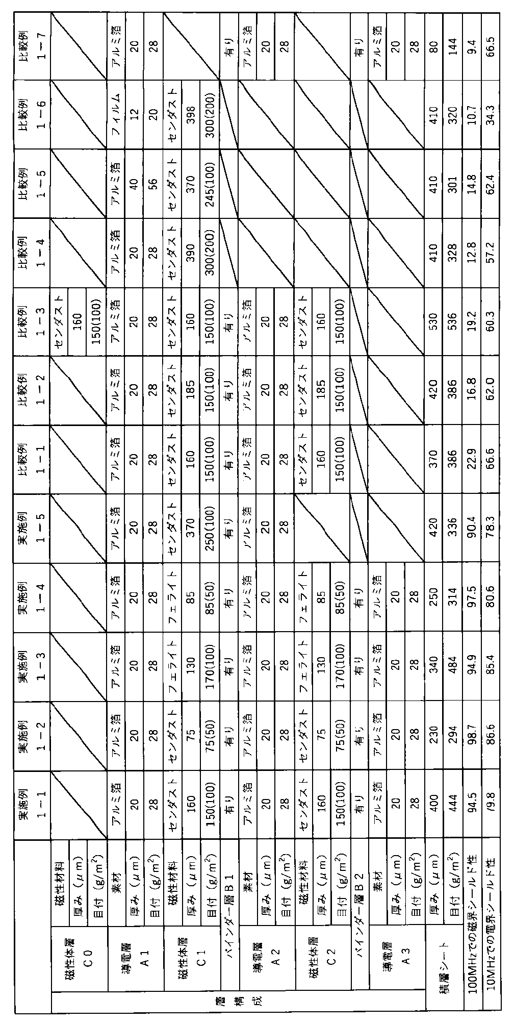
[実施例1-1]
アルミ箔(導電層)A1、磁性体層C1、バインダー層B1、アルミ箔(導電層)A2、磁性体層C2、バインダー層B2、アルミ箔(導電層)A3の順に積層された積層シートの製造方法を以下に説明する。
アルミ箔A2に上記磁性体層用樹脂組成物をコンマコーターにて1平方メートルあたり150g(乾燥重量)となるように塗布し、その後、乾燥機を用いて150℃で3分間乾燥させ、アルミ箔A2と磁性体層C2を備えた積層体L1を得た。次に、アルミ箔A3の一方の面に上記バインダー層用樹脂組成物をコンマコーターにて1平方メートルあたり30g(乾燥重量)となるように塗布し、塗布されたバインダー層用樹脂組成物の表面に積層体L1の磁性体層C2側の面を貼り合わせ、その後、120℃の乾燥機で1分間乾燥した後、60℃、10N/cm2の圧力条件で熱圧着し、常温にて48時間放置して、アルミ箔A2、磁性体層C2、バインダー層B2、アルミ箔A3の順に積層された積層体L2を得た。
続いて、アルミ箔A1に上記磁性体層用樹脂組成物をコンマコーターにて1平方メートルあたり150g(乾燥重量)となるように塗布し、その後、乾燥機を用いて150℃で3分間乾燥させ、アルミ箔A1の表面に磁性体層C1を形成した。次に、磁性体層C1の表面に上記バインダー層用樹脂組成物をコンマコーターにて1平方メートルあたり30g(乾燥重量)となるように塗布し、塗布されたバインダー層用樹脂組成物の表面に積層体L2のアルミ箔A2側の面を貼り合わせ、その後、120℃の乾燥機で1分間乾燥した後、60℃、10N/cm2の圧力条件で熱圧着し、常温にて48時間放置して、積層シートを得た。なお、磁性体層C1の目付は150g/m2、磁性体層C1における磁性材料であるセンダストの目付は100g/m2であり、磁性体層C2も同様であった。
[Example 1-1]
A method for manufacturing a laminated sheet in which aluminum foil (conductive layer) A1, magnetic layer C1, binder layer B1, aluminum foil (conductive layer) A2, magnetic layer C2, binder layer B2, and aluminum foil (conductive layer) A3 are laminated in this order is described below.
The above-mentioned resin composition for magnetic layer was applied to the aluminum foil A2 by a comma coater so as to be 150g (dry weight) per square meter, and then dried at 150°C for 3 minutes using a dryer to obtain a laminate L1 including the aluminum foil A2 and the magnetic layer C2. Next, the above-mentioned resin composition for binder layer was applied to one side of the aluminum foil A3 by a comma coater so as to be 30g (dry weight) per square meter, and the surface of the magnetic layer C2 side of the laminate L1 was bonded to the surface of the applied resin composition for binder layer, and then it was dried for 1 minute in a dryer at 120°C, and then it was thermocompressed under a pressure condition of 60°C and 10N/ cm2 , and left at room temperature for 48 hours to obtain a laminate L2 in which the aluminum foil A2, the magnetic layer C2, the binder layer B2, and the aluminum foil A3 were laminated in this order.
Next, the above-mentioned resin composition for magnetic layer was applied to the aluminum foil A1 by a comma coater so as to be 150 g (dry weight) per square meter, and then dried at 150 ° C. for 3 minutes using a dryer to form a magnetic layer C1 on the surface of the aluminum foil A1. Next, the above-mentioned resin composition for binder layer was applied to the surface of the magnetic layer C1 by a comma coater so as to be 30 g (dry weight) per square meter, and the surface of the aluminum foil A2 side of the laminate L2 was bonded to the surface of the applied resin composition for binder layer, and then dried for 1 minute in a dryer at 120 ° C., and then heat-pressed under a pressure condition of 60 ° C. and 10 N / cm 2 , and left at room temperature for 48 hours to obtain a laminate sheet. The basis weight of the magnetic layer C1 was 150 g / m 2 , and the basis weight of sendust, which is the magnetic material in the magnetic layer C1, was 100 g / m 2 , and the same was true for the magnetic layer C2.
[実施例1-2~1-4]
磁性体層用樹脂組成物の組成、塗布量を変更し、磁性体層C1及びC2の磁性材料、厚さ、目付を表1に記載の内容に変更した以外は、実施例1-1と同様にアルミ箔A1、磁性体層C1、バインダー層B1、アルミ箔A2、磁性体層C2、バインダー層B2、アルミ箔A3の順に積層された積層シートを作製した。
[Examples 1-2 to 1-4]
Except for changing the composition and application amount of the resin composition for the magnetic layer, and changing the magnetic material, thickness, and basis weight of the magnetic layers C1 and C2 to those shown in Table 1, a laminate sheet was prepared in the same order as in Example 1-1, in which aluminum foil A1, magnetic layer C1, binder layer B1, aluminum foil A2, magnetic layer C2, binder layer B2, and aluminum foil A3 were laminated.
[実施例1-5]
アルミ箔A1に上記磁性体層用樹脂組成物をコンマコーターにて1平方メートルあたり250g(乾燥重量)となるように塗布し、その後、乾燥機を用いて150℃で3分間乾燥させ、アルミ箔A1の表面に磁性体層C1を形成した。次に、磁性体層C1の表面に上記バインダー層用樹脂組成物をコンマコーターにて1平方メートルあたり30g(乾燥重量)となるように塗布し、塗布されたバインダー層用樹脂組成物の表面にアルミ箔A2を貼り合わせ、その後、120℃の乾燥機で1分間乾燥した後、60℃、10N/cm2の圧力条件で熱圧着し、常温にて48時間放置して、アルミ箔A1、磁性体層C1、バインダー層B1、アルミ箔A2の順に積層された積層シートを得た。
[Examples 1 to 5]
The above-mentioned resin composition for magnetic layer was applied to the aluminum foil A1 by a comma coater so as to be 250g (dry weight) per square meter, and then dried at 150°C for 3 minutes using a dryer to form a magnetic layer C1 on the surface of the aluminum foil A1. Next, the above-mentioned resin composition for binder layer was applied to the surface of the magnetic layer C1 by a comma coater so as to be 30g (dry weight) per square meter, and the aluminum foil A2 was laminated on the surface of the applied resin composition for binder layer, and then dried for 1 minute in a dryer at 120°C, followed by thermocompression bonding under pressure conditions of 60°C and 10N/ cm2 , and left at room temperature for 48 hours to obtain a laminated sheet in which the aluminum foil A1, the magnetic layer C1, the binder layer B1, and the aluminum foil A2 were laminated in this order.
[比較例1-1]
バインダー層B2及びアルミ箔A3を設けない以外は実施例1-1と同様に積層シートを作製した。
[Comparative Example 1-1]
A laminate sheet was produced in the same manner as in Example 1-1, except that the binder layer B2 and the aluminum foil A3 were not provided.
[比較例1-2]
磁性体層C1及びC2の厚さを185μmに変更した以外は比較例1-1と同様に積層シートを作製した。
[Comparative Example 1-2]
A laminate sheet was produced in the same manner as in Comparative Example 1-1, except that the thickness of the magnetic layers C1 and C2 was changed to 185 μm.
[比較例1-3]
比較例1-1の積層シートのアルミ箔A1側の面に上記磁性体層用樹脂組成物をコンマコーターにて1平方メートルあたり150g(乾燥重量)となるように塗布し、その後、乾燥機を用いて150℃で3分間乾燥させ、アルミ箔A1側の表面に磁性体層C0を形成した積層シートを得た。
[Comparative Example 1-3]
The above-mentioned resin composition for the magnetic layer was applied to the aluminum foil A1 side of the laminate sheet of Comparative Example 1-1 using a comma coater at 150 g (dry weight) per square meter, and then dried at 150°C for 3 minutes using a dryer to obtain a laminate sheet having a magnetic layer C0 formed on the surface of the aluminum foil A1 side.
[比較例1-4~1-6]
アルミ箔A1に上記磁性体層用樹脂組成物をコンマコーターにて塗布し、その後、乾燥機を用いて150℃で3分間乾燥させ、アルミ箔A1の表面に磁性体層C1を形成し、積層シートを得た。なお、磁性体層用樹脂組成物の組成、塗布量は、磁性体層C1の厚さ、目付を表1に記載の内容となるように調整した。また、比較例1-5ではアルミ箔A1に代えて、厚さ20μm、目付28g/m2の東洋アルミ社製アルミ箔を2枚重ねた厚さ40μm、目付58g/m2のアルミ箔を用いた。また、比較例1-6ではアルミ箔A1に代えて、厚さ12μm、目付20g/m2の東洋紡社製ポリエステルフィルムを用いた。
[Comparative Examples 1-4 to 1-6]
The above-mentioned resin composition for magnetic body layer was applied to the aluminum foil A1 by a comma coater, and then dried at 150 ° C. for 3 minutes using a dryer to form a magnetic body layer C1 on the surface of the aluminum foil A1, to obtain a laminated sheet. The composition and coating amount of the resin composition for magnetic body layer were adjusted so that the thickness and basis weight of the magnetic body layer C1 were the contents shown in Table 1. In addition, in Comparative Example 1-5, instead of the aluminum foil A1, an aluminum foil having a thickness of 40 μm and a basis weight of 58 g / m 2 was used, which was obtained by stacking two aluminum foils manufactured by Toyo Aluminum Co., Ltd., each having a thickness of 20 μm and a basis weight of 28 g / m 2. In addition, in Comparative Example 1-6, instead of the aluminum foil A1, a polyester film manufactured by Toyobo Co., Ltd., having a thickness of 12 μm and a basis weight of 20 g / m 2 was used.
[比較例1-7]
アルミ箔A1の表面に上記バインダー層用樹脂組成物をコンマコーターにて1平方メートルあたり30g(乾燥重量)となるように塗布し、塗布されたバインダー層用樹脂組成物の表面にアルミ箔A2を貼り合わせ、その後、120℃の乾燥機で1分間乾燥した後、60℃、10N/cm2の圧力条件で熱圧着し、常温にて48時間放置した。次に、アルミ箔A2の表面に上記バインダー層用樹脂組成物をコンマコーターにて1平方メートルあたり30g(乾燥重量)となるように塗布し、塗布されたバインダー層用樹脂組成物の表面にアルミ箔A3を貼り合わせ、その後、120℃の乾燥機で1分間乾燥した後、60℃、10N/cm2の圧力条件で熱圧着し、常温にて48時間放置して、アルミ箔A1、バインダー層B1、アルミ箔A2、バインダー層B2、アルミ箔A3の順に積層された積層シートを得た。
[Comparative Examples 1 to 7]
The above-mentioned resin composition for binder layer was applied to the surface of aluminum foil A1 by a comma coater so as to be 30 g (dry weight) per square meter, and aluminum foil A2 was laminated to the surface of the applied resin composition for binder layer, and then it was dried for 1 minute in a dryer at 120 ° C., and then it was heat-pressed at 60 ° C. and a pressure of 10 N / cm 2 , and it was left at room temperature for 48 hours. Next, the above-mentioned resin composition for binder layer was applied to the surface of aluminum foil A2 by a comma coater so as to be 30 g (dry weight) per square meter, and aluminum foil A3 was laminated to the surface of the applied resin composition for binder layer, and then it was dried for 1 minute in a dryer at 120 ° C., and then it was heat-pressed at 60 ° C. and a pressure of 10 N / cm 2 , and it was left at room temperature for 48 hours, and a laminated sheet in which aluminum foil A1, binder layer B1, aluminum foil A2, binder layer B2, and aluminum foil A3 were laminated in this order was obtained.
表1に実施例及び比較例における積層シートの層構成及び各層の物性、並びに積層シートのシールド性を記載した。なお、磁性体層の目付の欄において、括弧書きの数値は樹脂を含まない磁性材料のみの目付である。 Table 1 shows the layer structure and physical properties of each layer of the laminated sheet in the examples and comparative examples, as well as the shielding properties of the laminated sheet. Note that in the column for the basis weight of the magnetic layer, the value in parentheses is the basis weight of only the magnetic material, excluding the resin.
[実施例2-1]
アルミ箔(導電層)A1、磁性体層C1、バインダー層B1、不織布層N1、バインダー層B2、アルミ箔(導電層)A2、磁性体層C2、バインダー層B3、不織布層N2、バインダー層B4、アルミ箔(導電層)A3の順に積層された積層シートの製造方法を以下に説明する。
アルミ箔A3の表面に上記バインダー層用樹脂組成物をコンマコーターにて1平方メートルあたり30g(乾燥重量)となるように塗布し、バインダー層用樹脂組成物の上にポリエステル不織布を貼り合わせ、その後、120℃の乾燥機で1分間乾燥した後、60℃、10N/cm2の圧力条件で熱圧着し、常温にて48時間放置して、不織布層N2、バインダー層B4、アルミ箔A3の順に積層された積層体L1を得た。
アルミ箔A2の表面に上記磁性体層用樹脂組成物をコンマコーターにて1平方メートルあたり150g(乾燥重量)となるように塗布し、その後、乾燥機を用いて150℃で3分間乾燥させ、アルミ箔A2の表面に磁性体層C2を形成し、積層体L2を得た。なお、磁性体層C2の目付は150g/m2、磁性材料であるセンダストの目付は100g/m2であった。
積層体L2の磁性体層C2側の表面に上記バインダー層用樹脂組成物をコンマコーターにて1平方メートルあたり30g(乾燥重量)となるように塗布し、塗布されたバインダー層用樹脂組成物の上に積層体L1の不織布層N2側の面を貼り合わせ、その後、120℃の乾燥機で1分間乾燥した後、60℃、10N/cm2の圧力条件で熱圧着し、常温にて48時間放置して、アルミ箔A2、磁性体層C2、バインダー層B3、不織布層N2、バインダー層B4、アルミ箔A3の順に積層された積層体L3を得た。
アルミ箔A1の表面に上記磁性体層用樹脂組成物をコンマコーターにて1平方メートルあたり150g(乾燥重量)となるように塗布し、その後、乾燥機を用いて150℃で3分間乾燥させ、アルミ箔A1の表面に磁性体層C1を形成した。次に、磁性体層C1の表面に上記バインダー層用樹脂組成物をコンマコーターにて1平方メートルあたり30g(乾燥重量)となるように塗布し、塗布されたバインダー層用樹脂組成物の表面にポリエステル不織布を貼り合わせ、その後、120℃の乾燥機で1分間乾燥した後、60℃、10N/cm2の圧力条件で熱圧着し、常温にて48時間放置して、アルミ箔A1、磁性体層C1、バインダー層B1、不織布層N1の順に積層された積層体L4を得た。なお、磁性体層C1の目付は150g/m2、磁性材料であるセンダストの目付は100g/m2であった。
積層体L3のアルミ箔A2側の表面に上記バインダー層用樹脂組成物をコンマコーターにて1平方メートルあたり30g(乾燥重量)となるように塗布した後に、積層体L4の不織布層N1側の面を積層体L3に塗布されたバインダー層用樹脂組成物の上に積層した。最後に120℃の乾燥機で1分間乾燥した後、60℃、10N/cm2の圧力条件で熱圧着し、常温にて48時間放置して、積層シートを得た。
[Example 2-1]
A method for manufacturing a laminated sheet in which aluminum foil (conductive layer) A1, magnetic layer C1, binder layer B1, nonwoven fabric layer N1, binder layer B2, aluminum foil (conductive layer) A2, magnetic layer C2, binder layer B3, nonwoven fabric layer N2, binder layer B4, and aluminum foil (conductive layer) A3 are laminated in this order is described below.
The above-mentioned resin composition for binder layer was applied to the surface of the aluminum foil A3 using a comma coater so as to be 30 g (dry weight) per square meter, and a polyester nonwoven fabric was laminated on top of the resin composition for binder layer. Thereafter, the resultant was dried for 1 minute in a dryer at 120°C, and then heat-pressed under conditions of 60°C and a pressure of 10 N/ cm2 , and left at room temperature for 48 hours to obtain a laminate L1 in which the nonwoven fabric layer N2, the binder layer B4, and the aluminum foil A3 were laminated in this order.
The resin composition for the magnetic layer was applied to the surface of the aluminum foil A2 with a comma coater so as to be 150 g (dry weight) per square meter, and then dried at 150° C. for 3 minutes with a dryer to form a magnetic layer C2 on the surface of the aluminum foil A2, thereby obtaining a laminate L2. The magnetic layer C2 had a basis weight of 150 g/m 2 , and the magnetic material, sendust, had a basis weight of 100 g/m 2 .
The above-mentioned resin composition for the binder layer was applied to the surface of the magnetic layer C2 side of the laminate L2 using a comma coater at 30 g (dry weight) per square meter, and the surface of the nonwoven fabric layer N2 side of the laminate L1 was bonded onto the applied resin composition for the binder layer.Then, it was dried for 1 minute in a dryer at 120°C, and then thermocompressed under conditions of 60°C and a pressure of 10 N/ cm2 and left at room temperature for 48 hours to obtain a laminate L3 laminated in the following order: aluminum foil A2, magnetic layer C2, binder layer B3, nonwoven fabric layer N2, binder layer B4, and aluminum foil A3.
The above-mentioned resin composition for magnetic layer was applied to the surface of aluminum foil A1 by a comma coater so as to be 150g (dry weight) per square meter, and then dried at 150°C for 3 minutes using a dryer to form a magnetic layer C1 on the surface of aluminum foil A1. Next, the above-mentioned resin composition for binder layer was applied to the surface of magnetic layer C1 by a comma coater so as to be 30g (dry weight) per square meter, and a polyester nonwoven fabric was attached to the surface of the applied resin composition for binder layer, and then dried for 1 minute in a dryer at 120°C, and then heat-pressed under a pressure condition of 60°C and 10N/ cm2 , and left at room temperature for 48 hours to obtain a laminate L4 in which aluminum foil A1, magnetic layer C1, binder layer B1, and nonwoven fabric layer N1 were laminated in this order. The basis weight of the magnetic layer C1 was 150g/ m2 , and the basis weight of the magnetic material, sendust, was 100g/ m2 .
The above-mentioned resin composition for binder layer was applied to the surface of the aluminum foil A2 side of the laminate L3 by a comma coater so as to be 30 g (dry weight) per square meter, and then the surface of the nonwoven fabric layer N1 side of the laminate L4 was laminated on the resin composition for binder layer applied to the laminate L3. Finally, it was dried for 1 minute in a dryer at 120°C, and then heat-pressed at 60°C and a pressure of 10 N/ cm2 , and left at room temperature for 48 hours to obtain a laminate sheet.
[実施例2-2~2-4、比較例2-3]
磁性体層C1及びC2の磁性材料、厚さ、目付を表2に記載の内容に変更した以外は、実施例2-1と同様にアルミ箔A1、磁性体層C1、バインダー層B1、不織布層N1、バインダー層B2、アルミ箔A2、磁性体層C2、バインダー層B3、不織布層N2、バインダー層B4、磁性体層C3の順に積層された積層シートを作製した。
[Examples 2-2 to 2-4, Comparative Example 2-3]
Except for changing the magnetic material, thickness, and basis weight of the magnetic layers C1 and C2 to those shown in Table 2, a laminated sheet was prepared in the same order as in Example 2-1: aluminum foil A1, magnetic layer C1, binder layer B1, nonwoven fabric layer N1, binder layer B2, aluminum foil A2, magnetic layer C2, binder layer B3, nonwoven fabric layer N2, binder layer B4, and magnetic layer C3.
[比較例2-1]
アルミ箔A1の一方の表面に上記磁性体層用樹脂組成物をコンマコーターにて1平方メートルあたり150g(乾燥重量)となるように塗布し、その後、乾燥機を用いて150℃で3分間乾燥させ、アルミ箔A1の表面に磁性体層C0を形成した。次に、アルミ箔A1の他方の表面に上記バインダー層用樹脂組成物をコンマコーターにて1平方メートルあたり30g(乾燥重量)となるように塗布し、塗布されたバインダー層用樹脂組成物の表面にポリエステル不織布を貼り合わせ、その後、120℃の乾燥機で1分間乾燥した後、60℃、10N/cm2の圧力条件で熱圧着し、常温にて48時間放置して、磁性体層C0、アルミ箔A1、バインダー層B1、不織布層N1の順に積層された積層体L1を得た。また、積層体L1と同様の製造方法で磁性体層C2、アルミ箔A3、バインダー層B5、不織布層N3の順に積層された積層体L2を得た。積層体L1の不織布層N1側の表面に上記バインダー層用樹脂組成物をコンマコーターにて1平方メートルあたり30g(乾燥重量)となるように塗布し、塗布されたバインダー層用樹脂組成物の表面に積層体L2の磁性体層C2側の面を貼り合わせ、その後、120℃の乾燥機で1分間乾燥した後、60℃、10N/cm2の圧力条件で熱圧着し、常温にて48時間放置して、磁性体層C0、アルミ箔A1、バインダー層B1、不織布層N1、バインダー層B2、磁性体層C2、アルミ箔A3、バインダー層B5、不織布層N3の順に積層された積層体L3を得た。最後に積層体L3の不織布層N3側の表面に上記バインダー層用樹脂組成物をコンマコーターにて1平方メートルあたり30g(乾燥重量)となるように塗布し、塗布されたバインダー層用樹脂組成物の表面にアルミ箔A4を貼り合わせ、その後、120℃の乾燥機で1分間乾燥した後、60℃、10N/cm2の圧力条件で熱圧着し、常温にて48時間放置して、磁性体層C0、アルミ箔A1、バインダー層B1、不織布層N1、バインダー層B2、磁性体層C2、アルミ箔A3、バインダー層B5、不織布層N3、バインダー層B6、アルミ箔A4の順に積層された積層シートを得た。磁性体層C0及びアルミ箔A4(表2中の(*)を記した層)の厚さ、目付は、それぞれ磁性体層C1、アルミ箔A1と同じであった。
[Comparative Example 2-1]
The above-mentioned resin composition for magnetic layer was applied to one surface of the aluminum foil A1 by a comma coater so as to be 150 g (dry weight) per square meter, and then dried at 150 ° C. for 3 minutes using a dryer to form a magnetic layer C0 on the surface of the aluminum foil A1. Next, the above-mentioned resin composition for binder layer was applied to the other surface of the aluminum foil A1 by a comma coater so as to be 30 g (dry weight) per square meter, and a polyester nonwoven fabric was attached to the surface of the applied resin composition for binder layer, and then dried for 1 minute in a dryer at 120 ° C., and then heat-pressed under a pressure condition of 60 ° C. and 10 N / cm 2 , and left at room temperature for 48 hours to obtain a laminate L1 in which the magnetic layer C0, aluminum foil A1, binder layer B1, and nonwoven fabric layer N1 were laminated in this order. In addition, a laminate L2 was obtained by laminating the magnetic layer C2, the aluminum foil A3, the binder layer B5, and the nonwoven fabric layer N3 in this order using the same manufacturing method as the laminate L1. The binder layer resin composition was applied to the nonwoven fabric layer N1 side surface of the laminate L1 with a comma coater so as to be 30 g (dry weight) per square meter, and the magnetic layer C2 side surface of the laminate L2 was bonded to the surface of the applied binder layer resin composition, and then it was dried for 1 minute in a dryer at 120 ° C., and then it was thermocompressed under a pressure condition of 60 ° C. and 10 N / cm 2 , and left at room temperature for 48 hours to obtain a laminate L3 in which the magnetic layer C0, the aluminum foil A1, the binder layer B1, the nonwoven fabric layer N1, the binder layer B2, the magnetic layer C2, the aluminum foil A3, the binder layer B5, and the nonwoven fabric layer N3 were laminated in this order. Finally, the binder layer resin composition was applied to the surface of the nonwoven fabric layer N3 side of the laminate L3 with a comma coater so as to be 30 g (dry weight) per square meter, and aluminum foil A4 was laminated on the surface of the applied binder layer resin composition, and then it was dried for 1 minute in a dryer at 120 ° C., and then it was heat-pressed under a pressure condition of 60 ° C. and 10 N / cm 2 , and left at room temperature for 48 hours to obtain a laminated sheet in which the magnetic body layer C0, aluminum foil A1, binder layer B1, nonwoven fabric layer N1, binder layer B2, magnetic body layer C2, aluminum foil A3, binder layer B5, nonwoven fabric layer N3, binder layer B6, and aluminum foil A4 were laminated in this order. The thickness and basis weight of the magnetic body layer C0 and aluminum foil A4 (layers marked with (*) in Table 2) were the same as those of the magnetic body layer C1 and aluminum foil A1, respectively.
[比較例2-2]
比較例2-1と同様に積層体L3を作製した。積層体L3の不織布層N3側の表面に上記磁性体層用樹脂組成物をコンマコーターにて1平方メートルあたり150g(乾燥重量)となるように塗布し、その後、乾燥機を用いて150℃で3分間乾燥させ、磁性体層C0、アルミ箔A1、バインダー層B1、不織布層N1、バインダー層B2、磁性体層C2、アルミ箔A3、バインダー層B5、不織布層N3、磁性体層C3の順に積層された積層シートを得た。なお、磁性体層C0及びC3(表2中の(*)を記した層)の厚さ、目付は磁性体層C1と同じであった。
[Comparative Example 2-2]
The laminate L3 was prepared in the same manner as in Comparative Example 2-1. The above-mentioned resin composition for the magnetic layer was applied to the surface of the nonwoven fabric layer N3 side of the laminate L3 with a comma coater so as to be 150 g (dry weight) per square meter, and then dried at 150 ° C. for 3 minutes using a dryer to obtain a laminate sheet in which the magnetic layer C0, aluminum foil A1, binder layer B1, nonwoven fabric layer N1, binder layer B2, magnetic layer C2, aluminum foil A3, binder layer B5, nonwoven fabric layer N3, and magnetic layer C3 were laminated in this order. The thickness and basis weight of the magnetic layers C0 and C3 (layers marked with (*) in Table 2) were the same as those of the magnetic layer C1.
[比較例2-4]
積層体L1を作製しないこと、積層体L3に代えて、積層体L2の磁性体層C2側の表面に上記バインダー層用樹脂組成物をコンマコーターにて1平方メートルあたり30g(乾燥重量)となるように塗布し、塗布されたバインダー層用樹脂組成物の上にポリエステル不織布を貼り合わせ、その後、120℃の乾燥機で1分間乾燥した後、60℃、10N/cm2の圧力条件で熱圧着し、常温にて48時間放置して、アルミ箔A2、磁性体層C2、バインダー層B3、不織布層N2の順に積層された積層体L3’を作製して用いたこと以外は実施例2-1と同様に積層体を作製し、アルミ箔A1、磁性体層C1、バインダー層B1、不織布層N1、バインダー層B2、アルミ箔A2、磁性体層C2、バインダー層B3、不織布層N2の順に積層された積層シートを得た。
[Comparative Example 2-4]
The laminate L1 was not produced, and instead of the laminate L3, the above-mentioned resin composition for binder layer was applied to the surface of the magnetic layer C2 side of the laminate L2 with a comma coater so as to be 30 g (dry weight) per square meter, and a polyester nonwoven fabric was laminated on the applied resin composition for binder layer, and then dried for 1 minute in a dryer at 120 ° C., and then heat-pressed under a pressure condition of 60 ° C. and 10 N / cm 2 , and left at room temperature for 48 hours to produce and use a laminate L3' in which the aluminum foil A2, the magnetic layer C2, the binder layer B3, and the nonwoven fabric layer N2 were laminated in this order. A laminate was produced in the same manner as in Example 2-1, except that a laminate sheet was produced in which the aluminum foil A1, the magnetic layer C1, the binder layer B1, the nonwoven fabric layer N1, the binder layer B2, the aluminum foil A2, the magnetic layer C2, the binder layer B3, and the nonwoven fabric layer N2 were laminated in this order.
[比較例2-5]
実施例2-1と同様に積層体L4を作製し、積層体L4の不織布層N1側の表面に上記磁性体層用樹脂組成物をコンマコーターにて1平方メートルあたり160g(乾燥重量)となるように塗布し、その後、乾燥機を用いて150℃で3分間乾燥させ、不織布層N1の表面に磁性体層C2を形成して、アルミ箔A1、磁性体層C1、バインダー層B1、不織布層N1、磁性体層C2の順に積層された積層シートを得た。
[Comparative Example 2-5]
A laminate L4 was prepared in the same manner as in Example 2-1, and the above-mentioned resin composition for the magnetic layer was applied to the surface of the nonwoven fabric layer N1 side of the laminate L4 using a comma coater at 160 g (dry weight) per square meter, and then dried at 150°C for 3 minutes using a dryer to form a magnetic layer C2 on the surface of the nonwoven fabric layer N1, thereby obtaining a laminate sheet in which the aluminum foil A1, magnetic layer C1, binder layer B1, nonwoven fabric layer N1, and magnetic layer C2 were laminated in this order.
[比較例2-6]
アルミ箔A1の一方の表面に上記バインダー層用樹脂組成物をコンマコーターにて1平方メートルあたり30g(乾燥重量)となるように塗布し、塗布されたバインダー層用樹脂組成物の表面にポリエステル不織布を貼り合わせ、その後、120℃の乾燥機で1分間乾燥した後、60℃、10N/cm2の圧力条件で熱圧着し、常温にて48時間放置して、アルミ箔A1、バインダー層B1、不織布層N1の順に積層された積層体を得た。その後、上記積層体のアルミ箔A1とは反対側に位置する面に上記バインダー層用樹脂組成物をコンマコーターにて1平方メートルあたり30g(乾燥重量)となるように塗布し、塗布されたバインダー層用樹脂組成物の表面にポリエステル不織布又はアルミ箔を貼り合わせ、120℃の乾燥機で1分間乾燥した後、60℃、10N/cm2の圧力条件で熱圧着し、常温にて48時間放置することを繰り返すことにより、アルミ箔A1、バインダー層B1、不織布層N1、バインダー層B2、アルミ箔A2、バインダー層B3、不織布層N2、バインダー層B4、アルミ箔A3の順に積層された積層体を得た。
[Comparative Example 2-6]
The above-mentioned resin composition for binder layer was applied to one surface of aluminum foil A1 using a comma coater so as to be 30 g (dry weight) per square meter, and a polyester nonwoven fabric was attached to the surface of the applied resin composition for binder layer. Thereafter, the fabric was dried for 1 minute in a dryer at 120°C, and then heat-pressed at 60°C and a pressure of 10 N/ cm2. The fabric was then left at room temperature for 48 hours to obtain a laminate in which the aluminum foil A1, binder layer B1, and nonwoven fabric layer N1 were laminated in this order. Thereafter, the above-mentioned resin composition for binder layer was applied to the surface of the laminate opposite to the aluminum foil A1 using a comma coater at 30 g (dry weight) per square meter, and a polyester nonwoven fabric or aluminum foil was laminated to the surface of the applied resin composition for binder layer. The surface was then dried in a dryer at 120°C for 1 minute, and then heat-pressed at 60°C and a pressure of 10 N/ cm2. The resulting laminate was then left at room temperature for 48 hours, and this was repeated to obtain a laminate in which the aluminum foil A1, binder layer B1, nonwoven fabric layer N1, binder layer B2, aluminum foil A2, binder layer B3, nonwoven fabric layer N2, binder layer B4, and aluminum foil A3 were laminated in this order.
[比較例2-7]
ポリエステル不織布の表面に上記磁性体層用樹脂組成物をコンマコーターにて1平方メートルあたり180g(乾燥重量)となるように塗布し、その後、乾燥機を用いて150℃で3分間乾燥させ、磁性体層C1と不織布層N1との積層体L1を得た。次に、上記ポリエステル不織布とは別のポリエステル不織布の表面に上記磁性体層用樹脂組成物をコンマコーターにて1平方メートルあたり180g(乾燥重量)となるように塗布し、その後、乾燥機を用いて150℃で3分間乾燥させ、磁性体層C2と不織布層N2との積層体L2を得た。最後に、積層体L1の不織布層N1側の表面に上記バインダー層用樹脂組成物をコンマコーターにて1平方メートルあたり30g(乾燥重量)となるように塗布し、塗布されたバインダー層用樹脂組成物の表面に積層体L2の磁性体層C2側の面を貼り合わせ、その後、120℃の乾燥機で1分間乾燥した後、60℃、10N/cm2の圧力条件で熱圧着し、常温にて48時間放置して、磁性体層C1、不織布層N1、バインダー層B2、磁性体層C2、不織布層N2の順に積層された積層シートを得た。
[Comparative Example 2-7]
The above-mentioned resin composition for magnetic layer was applied to the surface of polyester nonwoven fabric by a comma coater so as to be 180 g (dry weight) per square meter, and then dried for 3 minutes at 150° C. using a dryer to obtain a laminate L1 of magnetic layer C1 and nonwoven fabric layer N1. Next, the above-mentioned resin composition for magnetic layer was applied to the surface of polyester nonwoven fabric other than the above-mentioned polyester nonwoven fabric by a comma coater so as to be 180 g (dry weight) per square meter, and then dried for 3 minutes at 150° C. using a dryer to obtain a laminate L2 of magnetic layer C2 and nonwoven fabric layer N2. Finally, the above-mentioned resin composition for the binder layer was applied to the surface of the nonwoven fabric layer N1 side of the laminate L1 using a comma coater at 30 g (dry weight) per square meter, and the surface of the magnetic layer C2 side of the laminate L2 was bonded to the surface of the applied resin composition for the binder layer.Then, it was dried for 1 minute in a dryer at 120°C, and then heat-pressed under conditions of 60°C and a pressure of 10 N/ cm2 and left at room temperature for 48 hours to obtain a laminate sheet in which the magnetic layer C1, nonwoven fabric layer N1, binder layer B2, magnetic layer C2, and nonwoven fabric layer N2 were stacked in that order.
[比較例2-8]
実施例2-1と同様に積層体L1を作製し、積層体L1の不織布層N2側の表面に上記磁性体層用樹脂組成物をコンマコーターにて1平方メートルあたり595g(乾燥重量)となるように塗布し、その後、乾燥機を用いて150℃で3分間乾燥させ、アルミ箔A2の表面に磁性体層C2を形成して積層シートを得た。
[Comparative Example 2-8]
A laminate L1 was prepared in the same manner as in Example 2-1, and the above-mentioned resin composition for the magnetic layer was applied to the surface of the nonwoven fabric layer N2 side of the laminate L1 using a comma coater at 595 g (dry weight) per square meter, and then dried at 150°C for 3 minutes using a dryer to form a magnetic layer C2 on the surface of the aluminum foil A2, thereby obtaining a laminate sheet.
[比較例2-9]
磁性体層C1及びC2の磁性材料、厚さ、目付を表2に記載の内容に変更し、上記ポリエステル不織布を2枚重ねて不織布層N1とした以外は、実施例2-1と同様に積層体L4を作製して積層シートとした。
[Comparative Example 2-9]
A laminate L4 was produced in the same manner as in Example 2-1, except that the magnetic material, thickness, and basis weight of the magnetic layers C1 and C2 were changed to those shown in Table 2, and two sheets of the above polyester nonwoven fabric were stacked to form the nonwoven fabric layer N1. A laminate sheet was produced.
表2に実施例及び比較例における積層シートの層構成及び各層の物性、並びに積層シートのシールド性を記載した。なお、磁性体層の目付の欄において、括弧書きの数値は樹脂を含まない磁性材料のみの目付である。 Table 2 shows the layer structure and physical properties of each layer of the laminated sheet in the examples and comparative examples, as well as the shielding properties of the laminated sheet. Note that in the column for the basis weight of the magnetic layer, the value in parentheses is the basis weight of only the magnetic material, excluding the resin.
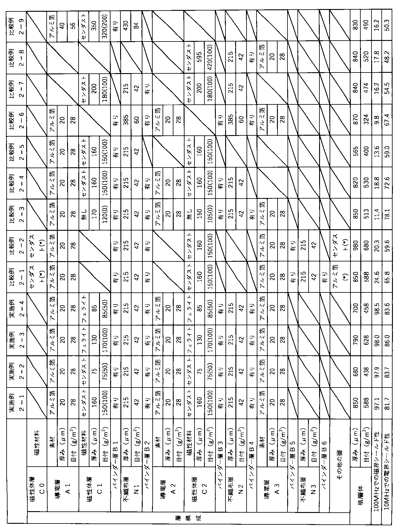
実施例1-1~1-5及び実施例2-1~2-4では積層シートが所定の層構成であるため、電磁波シールド性に優れている。 In Examples 1-1 to 1-5 and Examples 2-1 to 2-4, the laminated sheets have a specified layer structure, and therefore have excellent electromagnetic wave shielding properties.
Claims (6)
前記電磁波シールドシートの一方の主面が前記第1導電層であり、他方の主面が前記第2導電層であり、前記第1導電層と前記第2導電層との間に前記磁性体層を有し、
前記第1導電層及び前記第2導電層はいずれも導電性材料を含み、前記磁性体層は磁性材料を含むことを特徴とする電磁波シールドシート。 An electromagnetic wave shielding sheet including a first conductive layer, a second conductive layer, and a magnetic layer,
one main surface of the electromagnetic wave shielding sheet is the first conductive layer, the other main surface is the second conductive layer, and the magnetic layer is disposed between the first conductive layer and the second conductive layer;
The electromagnetic wave shielding sheet, wherein the first conductive layer and the second conductive layer each contain a conductive material, and the magnetic layer contains a magnetic material.
Priority Applications (1)
| Application Number | Priority Date | Filing Date | Title |
|---|---|---|---|
| JP2023148440A JP2025041254A (en) | 2023-09-13 | 2023-09-13 | Electromagnetic wave shielding sheet |
Applications Claiming Priority (1)
| Application Number | Priority Date | Filing Date | Title |
|---|---|---|---|
| JP2023148440A JP2025041254A (en) | 2023-09-13 | 2023-09-13 | Electromagnetic wave shielding sheet |
Publications (1)
| Publication Number | Publication Date |
|---|---|
| JP2025041254A true JP2025041254A (en) | 2025-03-26 |
Family
ID=95105095
Family Applications (1)
| Application Number | Title | Priority Date | Filing Date |
|---|---|---|---|
| JP2023148440A Pending JP2025041254A (en) | 2023-09-13 | 2023-09-13 | Electromagnetic wave shielding sheet |
Country Status (1)
| Country | Link |
|---|---|
| JP (1) | JP2025041254A (en) |
-
2023
- 2023-09-13 JP JP2023148440A patent/JP2025041254A/en active Pending
Similar Documents
| Publication | Publication Date | Title |
|---|---|---|
| CN104885587B (en) | Electromagnetic wave absorbing plate, manufacturing method thereof, and electronic device including same | |
| JP6534418B2 (en) | Antenna device comprising magnetic sheet and magnetic sheet | |
| KR102138887B1 (en) | Chip electronic component and manufacturing method thereof | |
| JP6004108B2 (en) | Electronic components | |
| CN108292804B (en) | Multifunctional composite module and portable equipment comprising same | |
| US9743566B2 (en) | Clad type electromagnetic shielding material and method for manufacturing the same | |
| JP2010153542A (en) | Electromagnetic wave suppression sheet and method of manufacturing the same | |
| JPWO2003021610A1 (en) | Laminated soft magnetic member, soft magnetic sheet, and method of manufacturing laminated soft magnetic member | |
| WO2012164925A1 (en) | Electrically conductive sheet and process for producing same, and electronic component | |
| WO2008053662A1 (en) | Process for the production of laminate-type soft magnetic sheets | |
| JP2011187559A (en) | Contactless power transmission film | |
| KR101019963B1 (en) | Electromagnetic shielding sheet and its manufacturing method | |
| JP2006210541A (en) | Inductor | |
| KR20200045604A (en) | Antenna device and preparation method thereof | |
| TWI313148B (en) | Switching power supply , electronic maching and power supply device | |
| JP2025041254A (en) | Electromagnetic wave shielding sheet | |
| JP2025041253A (en) | Electromagnetic wave shielding sheet | |
| KR20180062790A (en) | Composition for complex sheet with emi shields and absorbing and thermal dissipation, and complex sheet comprising the same | |
| JP2020113850A (en) | Laminated antenna and method of manufacturing laminated antenna | |
| CN108297502A (en) | A kind of the FCCL materials and its manufacturing method of soft magnetic materials base material | |
| KR102459013B1 (en) | Electromagnetic wave absorber and preparing method thereof | |
| KR20240060666A (en) | Electromagnetic wave shielding materials, coverings or exterior materials and electrical/electronic devices | |
| KR20240103868A (en) | Electromagnetic wave absorber and preparing method thereof | |
| JP2004281814A (en) | Manufacturing method for laminated soft magnetic member and soft magnetic sheet, and heat treatment method for laminated soft magnetic member | |
| JP2017118046A (en) | Electromagnetic wave shield material and manufacturing method thereof |