JP2025041201A - Differential device - Google Patents
Differential device Download PDFInfo
- Publication number
- JP2025041201A JP2025041201A JP2023148350A JP2023148350A JP2025041201A JP 2025041201 A JP2025041201 A JP 2025041201A JP 2023148350 A JP2023148350 A JP 2023148350A JP 2023148350 A JP2023148350 A JP 2023148350A JP 2025041201 A JP2025041201 A JP 2025041201A
- Authority
- JP
- Japan
- Prior art keywords
- gear
- differential
- cam
- cam surface
- operating
- Prior art date
- Legal status (The legal status is an assumption and is not a legal conclusion. Google has not performed a legal analysis and makes no representation as to the accuracy of the status listed.)
- Pending
Links
Images

Classifications
-
- F—MECHANICAL ENGINEERING; LIGHTING; HEATING; WEAPONS; BLASTING
- F16—ENGINEERING ELEMENTS AND UNITS; GENERAL MEASURES FOR PRODUCING AND MAINTAINING EFFECTIVE FUNCTIONING OF MACHINES OR INSTALLATIONS; THERMAL INSULATION IN GENERAL
- F16H—GEARING
- F16H48/00—Differential gearings
- F16H48/06—Differential gearings with gears having orbital motion
- F16H48/08—Differential gearings with gears having orbital motion comprising bevel gears
-
- F—MECHANICAL ENGINEERING; LIGHTING; HEATING; WEAPONS; BLASTING
- F16—ENGINEERING ELEMENTS AND UNITS; GENERAL MEASURES FOR PRODUCING AND MAINTAINING EFFECTIVE FUNCTIONING OF MACHINES OR INSTALLATIONS; THERMAL INSULATION IN GENERAL
- F16H—GEARING
- F16H48/00—Differential gearings
- F16H48/06—Differential gearings with gears having orbital motion
-
- B—PERFORMING OPERATIONS; TRANSPORTING
- B60—VEHICLES IN GENERAL
- B60K—ARRANGEMENT OR MOUNTING OF PROPULSION UNITS OR OF TRANSMISSIONS IN VEHICLES; ARRANGEMENT OR MOUNTING OF PLURAL DIVERSE PRIME-MOVERS IN VEHICLES; AUXILIARY DRIVES FOR VEHICLES; INSTRUMENTATION OR DASHBOARDS FOR VEHICLES; ARRANGEMENTS IN CONNECTION WITH COOLING, AIR INTAKE, GAS EXHAUST OR FUEL SUPPLY OF PROPULSION UNITS IN VEHICLES
- B60K17/00—Arrangement or mounting of transmissions in vehicles
- B60K17/04—Arrangement or mounting of transmissions in vehicles characterised by arrangement, location or kind of gearing
- B60K17/16—Arrangement or mounting of transmissions in vehicles characterised by arrangement, location or kind of gearing of differential gearing
-
- F—MECHANICAL ENGINEERING; LIGHTING; HEATING; WEAPONS; BLASTING
- F16—ENGINEERING ELEMENTS AND UNITS; GENERAL MEASURES FOR PRODUCING AND MAINTAINING EFFECTIVE FUNCTIONING OF MACHINES OR INSTALLATIONS; THERMAL INSULATION IN GENERAL
- F16H—GEARING
- F16H48/00—Differential gearings
- F16H48/12—Differential gearings without gears having orbital motion
- F16H48/14—Differential gearings without gears having orbital motion with cams
-
- F—MECHANICAL ENGINEERING; LIGHTING; HEATING; WEAPONS; BLASTING
- F16—ENGINEERING ELEMENTS AND UNITS; GENERAL MEASURES FOR PRODUCING AND MAINTAINING EFFECTIVE FUNCTIONING OF MACHINES OR INSTALLATIONS; THERMAL INSULATION IN GENERAL
- F16H—GEARING
- F16H48/00—Differential gearings
- F16H48/20—Arrangements for suppressing or influencing the differential action, e.g. locking devices
- F16H48/22—Arrangements for suppressing or influencing the differential action, e.g. locking devices using friction clutches or brakes
-
- F—MECHANICAL ENGINEERING; LIGHTING; HEATING; WEAPONS; BLASTING
- F16—ENGINEERING ELEMENTS AND UNITS; GENERAL MEASURES FOR PRODUCING AND MAINTAINING EFFECTIVE FUNCTIONING OF MACHINES OR INSTALLATIONS; THERMAL INSULATION IN GENERAL
- F16H—GEARING
- F16H48/00—Differential gearings
- F16H48/20—Arrangements for suppressing or influencing the differential action, e.g. locking devices
- F16H48/28—Arrangements for suppressing or influencing the differential action, e.g. locking devices using self-locking gears or self-braking gears
-
- F—MECHANICAL ENGINEERING; LIGHTING; HEATING; WEAPONS; BLASTING
- F16—ENGINEERING ELEMENTS AND UNITS; GENERAL MEASURES FOR PRODUCING AND MAINTAINING EFFECTIVE FUNCTIONING OF MACHINES OR INSTALLATIONS; THERMAL INSULATION IN GENERAL
- F16H—GEARING
- F16H48/00—Differential gearings
- F16H48/38—Constructional details
- F16H48/40—Constructional details characterised by features of the rotating cases
-
- F—MECHANICAL ENGINEERING; LIGHTING; HEATING; WEAPONS; BLASTING
- F16—ENGINEERING ELEMENTS AND UNITS; GENERAL MEASURES FOR PRODUCING AND MAINTAINING EFFECTIVE FUNCTIONING OF MACHINES OR INSTALLATIONS; THERMAL INSULATION IN GENERAL
- F16H—GEARING
- F16H57/00—General details of gearing
- F16H57/02—Gearboxes; Mounting gearing therein
- F16H57/037—Gearboxes for accommodating differential gearings
-
- F—MECHANICAL ENGINEERING; LIGHTING; HEATING; WEAPONS; BLASTING
- F16—ENGINEERING ELEMENTS AND UNITS; GENERAL MEASURES FOR PRODUCING AND MAINTAINING EFFECTIVE FUNCTIONING OF MACHINES OR INSTALLATIONS; THERMAL INSULATION IN GENERAL
- F16H—GEARING
- F16H48/00—Differential gearings
- F16H48/20—Arrangements for suppressing or influencing the differential action, e.g. locking devices
- F16H2048/204—Control of arrangements for suppressing differential actions
- F16H2048/207—Control of arrangements for suppressing differential actions using torque sensors
Landscapes
- Engineering & Computer Science (AREA)
- General Engineering & Computer Science (AREA)
- Mechanical Engineering (AREA)
- Chemical & Material Sciences (AREA)
- Combustion & Propulsion (AREA)
- Transportation (AREA)
- Retarders (AREA)
Abstract
Description
本発明は、デファレンシャル装置に関する。 The present invention relates to a differential device.
従来、デファレンシャル装置としては、回転可能に配置されたデフケースと、デフケースに自転可能に支持され、デフケースの回転によって公転する差動ギヤと、差動ギヤと噛み合い、相対回転可能な一対の出力ギヤとを備えている。また、デフケースと出力ギヤとの間で摺動摩擦可能に設けられ、一対の出力ギヤの差動を制限する差動制限部と、出力ギヤに入力する駆動トルクで差動制限部を作動させるカム部とを備えたものが知られている(特許文献1参照)。 Conventionally, a differential device includes a rotatably arranged differential case, a differential gear supported on the differential case so as to be rotatable and revolving with the rotation of the differential case, and a pair of output gears that mesh with the differential gear and can rotate relative to each other. Also known is a differential limiting section that is provided between the differential case and the output gears so as to be capable of sliding friction and that limits the differential between the pair of output gears, and a cam section that operates the differential limiting section with the driving torque input to the output gears (see Patent Document 1).
このデファレンシャル装置では、出力ギヤが、差動ギヤと噛み合うギヤ部材と、軸方向移動可能に配置されギヤ部材とカム部を介して一体回転可能に係合され差動制限部を作動させる作動部材とを有する。カム部は、ギヤ部材に設けられ軸方向に突出し周方向に複数配置されたギヤ凸部と、作動部材に設けられ軸方向に突出し周方向に複数配置され隣り合うギヤ凸部に係合可能な作動凸部とを有する。ギヤ凸部と作動凸部との互いの回転方向の対向面には、それぞれカム面が設けられている。 In this differential device, the output gear has a gear member that meshes with the differential gear, and an operating member that is arranged to be movable in the axial direction and engages with the gear member via the cam portion so as to be rotatable together, thereby operating the differential limiting portion. The cam portion has gear protrusions that are provided on the gear member, protrude in the axial direction, and are arranged in a plurality of circumferential directions, and operating protrusions that are provided on the operating member, protrude in the axial direction, and are arranged in a plurality of circumferential directions and can engage with adjacent gear protrusions. Cam surfaces are provided on the opposing surfaces of the gear protrusions and the operating protrusions in the rotational direction.
このようなデファレンシャル装置では、デフケースに駆動トルクが入力されると、差動ギヤから一対の出力ギヤに分岐して駆動トルクが入力される。一対の出力ギヤに入力された駆動トルクにより、カム部のカム面が作動して作動部材を差動制限部に向けて移動させる。作動部材の移動により、差動制限部における差動制限力である摺動摩擦が増大・強化される。 In this type of differential device, when a driving torque is input to the differential case, it is branched from the differential gear to a pair of output gears and input. The driving torque input to the pair of output gears activates the cam surface of the cam portion, moving the operating member toward the differential limiting section. The movement of the operating member increases and strengthens the sliding friction, which is the differential limiting force in the differential limiting section.
ところで、上記特許文献1のようなデファレンシャル装置では、一対の出力ギヤが回転したとき、カム部において、回転方向に対向するギヤ凸部のカム面と、作動凸部のカム面とが係合される。このとき、ギヤ凸部及び作動凸部の先端側の角部に、バリやカエリなどのエッジ状部分が僅かでも残っていると、カム面同士より先に、エッジ状部分がカム面に接触してしまう。エッジ状部分が先にカム面に接触すると、カム部で発生するカムスラスト力に影響を与え、差動制限部における差動制限特性が変化してしまう可能性があった。
In a differential device such as that disclosed in
そこで、この発明は、差動制限部における差動制限特性を安定化することができるデファレンシャル装置の提供を目的としている。 Therefore, the purpose of this invention is to provide a differential device that can stabilize the differential limiting characteristics in the differential limiting section.
本実施形態に係るデファレンシャル装置は、回転可能に配置されたデフケースと、前記デフケースに自転可能に支持され、前記デフケースの回転によって公転する差動ギヤと、前記差動ギヤと噛み合い、相対回転可能な一対の出力ギヤと、前記デフケースと前記出力ギヤとの間で摺動摩擦可能に設けられ、一対の前記出力ギヤの差動を制限する差動制限部と、前記出力ギヤに入力する駆動トルクで前記差動制限部を作動させるカム部とを備え、前記出力ギヤは、前記差動ギヤと噛み合うギヤ部材と、軸方向移動可能に配置され前記ギヤ部材と前記カム部を介して一体回転可能に係合され前記差動制限部を作動させる作動部材とを有し、前記カム部は、前記ギヤ部材に設けられ軸方向に突出し周方向に複数配置されたギヤ凸部と、前記作動部材に設けられ軸方向に突出し周方向に複数配置され隣り合う前記ギヤ凸部に係合可能な作動凸部と、前記ギヤ凸部と前記作動凸部との互いの回転方向の対向面にそれぞれ設けられたカム面とを有し、前記ギヤ凸部と前記作動凸部とのうち少なくとも一方の先端側の角部は、前記カム面の当接面積を保持して前記カム面から後退するように形成された後退部を有する。 The differential device according to this embodiment includes a rotatably arranged differential case, a differential gear supported on the differential case so as to be rotatable about its axis and revolving with the rotation of the differential case, a pair of output gears meshing with the differential gear and capable of relative rotation, a differential limiting section provided between the differential case and the output gear so as to be capable of sliding friction and limiting the differential between the pair of output gears, and a cam section that operates the differential limiting section with a driving torque input to the output gear, and the output gear includes a gear member that meshes with the differential gear, and a gear member that is arranged axially movable and a cam section that is arranged between the gear member and the cam section. and an operating member that is engaged with the gear member so as to be rotatable together via the cam portion and operates the differential limiting portion. The cam portion has gear protrusions that are provided on the gear member and protrude in the axial direction and are arranged in a circumferential direction, operating protrusions that are provided on the operating member and protrude in the axial direction and are arranged in a circumferential direction and can engage with adjacent gear protrusions, and cam surfaces that are provided on the opposing surfaces of the gear protrusions and the operating protrusions in the rotational direction, and a corner portion on the tip side of at least one of the gear protrusions and the operating protrusions has a retraction portion that is formed to retract from the cam surface while maintaining the contact area of the cam surface.
本発明によれば、差動制限部における差動制限特性を安定化することができるデファレンシャル装置を提供することができるという効果を奏する。 The present invention has the effect of providing a differential device that can stabilize the differential limiting characteristics in the differential limiting section.
以下、図面を用いて本実施形態に係るデファレンシャル装置について詳細に説明する。なお、図面の寸法比率は説明の都合上誇張されており、実際の比率と異なる場合がある。 The differential device according to this embodiment will be described in detail below with reference to the drawings. Note that the dimensional ratios in the drawings have been exaggerated for the sake of explanation and may differ from the actual ratios.
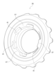
図1に示すように、本実施形態に係るデファレンシャル装置1は、例えば、エンジンや電動モータなどの駆動源(不図示)と、左右の車輪(不図示)との間に配置されている。駆動源からの駆動力は、トランスミッション(不図示)を介してデファレンシャル装置1に伝達され、一対の出力軸(不図示)を介して左右の車輪に駆動力が配分される。
As shown in FIG. 1, the
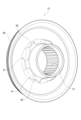
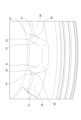
図1~図4に示すように、デファレンシャル装置1は、差動機構3と、差動制限部5とを備えている。
As shown in Figures 1 to 4, the
差動機構3は、デフケース7と、ピニオンシャフト9と、差動ギヤ11と、一対の出力ギヤ13,15とを備えている。
The
デフケース7は、軸方向両側に形成されたボス部17,19のそれぞれの外周でベアリング(不図示)を介してキャリアなどの静止系部材(不図示)に回転可能に支持されている。デフケース7には、リングギヤ(不図示)が固定されるフランジ部21が形成されている。フランジ部21に固定されたリングギヤは、駆動力を伝達する動力伝達ギヤ(不図示)と噛み合い、駆動力が伝達されてデフケース7を回転駆動させる。デフケース7内には、ピニオンシャフト9と、差動ギヤ11と、一対の出力ギヤ13,15などが収容配置されている。
The
ピニオンシャフト9は、端部をデフケース7に形成された孔部に係合してピン23で抜け止め及び回り止めされ、デフケース7と一体に回転駆動される。ピニオンシャフト9の両軸端側には、差動ギヤ11がそれぞれ支承されている。
The
差動ギヤ11は、デフケース7の周方向等間隔に複数(ここでは2つ)配置され、それぞれピニオンシャフト9の軸端部側に支承されてデフケース7の回転によって公転する。差動ギヤ11は、一対の出力ギヤ13,15に駆動力を伝達すると共に、噛み合っている一対の出力ギヤ13,15に差回転が生じると回転駆動されるようにピニオンシャフト9に自転可能に支持されている。
Multiple differential gears 11 (two in this example) are arranged at equal intervals around the circumferential direction of the
一対の出力ギヤ13,15は、デフケース7内に相対回転可能に収容されている。一対の出力ギヤ13,15は、それぞれギヤ部材25と、作動部材27とからなる。なお、一対の出力ギヤ13,15において、ギヤ部材25と作動部材27とは、左右対称に形成されているので、以下では主に一方のみについて説明し、他方については説明を省略する。
The pair of
ギヤ部材25は、環状に形成され、外周側に差動ギヤ11と噛み合うギヤ部が形成されている。ギヤ部材25は、差動ギヤ11と噛み合うことにより、差動ギヤ11から一対の出力ギヤ13,15に駆動力が伝達される。加えて、一対の出力ギヤ13,15に差回転が生じたときに、差動ギヤ11を回転させる。
The
作動部材27は、ギヤ部材25と軸方向に近接して配置可能なように、ギヤ部材25の軸方向の一部を収容可能に凹状の環状に形成されている。作動部材27のギヤ部材25の径方向外側に位置する部分には、軸方向に円錐状に傾斜された摺動面29が設けられている。作動部材27の内周側には、一対の出力ギヤ13,15において、一対の出力軸に一体回転可能に連結可能なスプライン形状の出力部31,33が形成されている。作動部材27は、デフケース7から一対の出力ギヤ13,15に入力された駆動力を、一対の出力軸を介して左右の車輪に出力する。
The actuating
ギヤ部材25と作動部材27との軸方向間には、回転トルクを軸方向スラスト力に変換するカム部35が設けられている。カム部35は、ギヤ部材25の内周側に設けられた複数のギヤ凸部37と、作動部材27の外周側に設けられ隣り合うギヤ凸部37,37の間に係合可能な複数の作動凸部39とからなる。カム部35は、ギヤ凸部37と作動凸部39とを回転方向に係合することにより、ギヤ部材25と作動部材27とを一体回転可能とさせる。
A
一方、カム部35では、複数のギヤ凸部37と複数の作動凸部39との回転方向の係合面が、それぞれ所定角度傾斜されたカム面41となっている。カム部35におけるカム面41は、デフケース7に駆動力(駆動トルク)が入力されたとき、差動ギヤ11から一対の出力ギヤ13,15に分岐して入力された駆動力により、カム部35が作動して作動部材27を軸方向外側に移動させる。カム部35による作動部材27の軸方向移動により、デフケース7と一対の出力ギヤ13,15との間に配置された差動制限部5における差動制限力を増大・強化することができる。
On the other hand, in the
差動制限部5は、デフケース7と一対の出力ギヤ13,15との間にそれぞれ配置されている。差動制限部5は、互いに摺動するテーパリング43と作動部材27とを有する。
The differential limiting
テーパリング43は、デフケース7に対して、一対の出力ギヤ13,15の作動部材27の摺動面29と対応する位置にそれぞれ配置されている。テーパリング43は、内周側に周方向に複数形成された凸部を、デフケース7の内壁面に形成された凹部に係合させることにより、デフケース7と一体に回転する。
The
テーパリング43は、デフケース7に入力される駆動力(駆動トルク)の大きさに応じて、差動ギヤ11との噛み合い反力を受けて軸方向に移動された一対の出力ギヤ13,15の作動部材27の摺動面29と摺動する。このとき、差動制限部5の差動制限力であるテーパリング43と摺動面29との摺動摩擦は、カム部35のカムスラスト力によって増大・強化される。
The
差動制限部5は、カムスラスト力の大きさに対応して、デフケース7と一対の出力ギヤ13,15との間に摩擦トルクを伝達させ、差動機構3の差動を制限する。このような差動制限部5は、トルク感応型の摩擦クラッチのうちコーンクラッチタイプとなっている。差動制限部5は、付勢部材45によって予圧が付与されている。
The differential limiting
付勢部材45は、皿バネからなり、ギヤ部材25と作動部材27との軸方向間に配置されている。付勢部材45は、ギヤ部材25を軸方向内側(差動ギヤ11側)に付勢し、作動部材27を軸方向外側(差動制限部5側)に付勢する。ギヤ部材25と作動部材27との間に付勢部材45を配置することにより、差動制限部5に対して予圧を付与し、差動制限部5の断続特性を安定化することができる。
The
このようなデファレンシャル装置1において、カム部35では、複数のギヤ凸部37と複数の作動凸部39との回転方向の係合面に形成されたカム面41が係合することにより、作動部材27を軸方向移動させるカムスラスト力を発生する。ギヤ凸部37と作動凸部39の先端側の角部には、バリやカエリなどのエッジ状部分が残っていることがあり、エッジ状部分はカム面41より回転方向に突出していることがある。ギヤ凸部37と作動凸部39のカム面41の係合において、エッジ状部分がカム面41より突出していると、エッジ状部分が、自身のカム面41より先に相手側のカム面41に接触する可能性がある。エッジ状部分が先にカム面41に接触してしまうと、カム部35で発生するカムスラスト力に影響を与え、差動制限部5における差動制限特性が変化してしまう可能性があった。
In such a
そこで、ギヤ凸部37と作動凸部39とのうち少なくとも一方の先端側の角部47は、カム面41の当接面積を保持してカム面41から後退するように形成された後退部49を有している。なお、以下では、作動凸部39の角部47に後退部49が設けられているものとして説明するが、ギヤ凸部37の先端側の角部に後退部49を設けてもよい。
Therefore, at least one of the
作動凸部39の角部47には、カム面41より回転方向に突出しないように、面取り加工などによって、カム面41から後退するように形成された後退部49が設けられている。角部47に後退部49を設けることにより、角部47において、カム面41より回転方向に突出したバリやカエリなどのエッジ状部分が発生することがない。このため、エッジ状部分が先にカム面41に接触することがなく、ギヤ凸部37と作動凸部39のカム面41を安定して接触させることができる。後退部49は、カム部35で発生する設定されたカムスラスト力に影響を与えないように、カム面41の当接面積を保持して角部47に対して設けられている。このため、ギヤ凸部37と作動凸部39のカム面41の当接面積が減少することがなく、カム部35でカムスラスト力を安定して発生することができ、差動制限部5における差動制限特性を安定化することができる。
The
作動凸部39の角部47には、3つの稜線部が連続して形成されている。3つの稜線部のうち少なくとも1つの稜線部51は、面取り加工などによって、平面又は曲面で形成されている。平面又は曲面で形成された稜線部51は、カム面41と連続していない稜線部となっている。このため、稜線部51を平面又は曲面で形成しても、カム面41の当接面積に影響を与えることがない。平面又は曲面で形成された稜線部51は、後退部49に連続して形成されている。稜線部51を後退部49に連続させることにより、稜線部51の後退部49と連続する部分にバリやカエリなどのエッジ状部分が発生することを防止することができる。なお、カム面41と連続する稜線部を後退部49と連続させる場合には、カム面41の当接面積を保持するように、平面又は曲面で形成して後退部49と連続させればよい。
Three ridges are formed continuously at the
後退部49は、角部47の最も突出した部分が、カム面41から回転方向に後退するように、平面又は曲面で形成され、カム面41と連続するように設けられている。後退部49の平面又は曲面は、カム面41との間に成す角度が鋭角となるように、カム面41との接線53を介して接続されている。後退部49がカム面41の接線53から鋭角に接続される面を有することにより、後退部49の面がカム面41より回転方向に突出することがない。このため、ギヤ凸部37と作動凸部39のカム面41を安定して接触させることができる。加えて、後退部49を平面又は曲面で形成し、カム面41と接続することにより、後退部49の広い範囲でバリやカエリなどのエッジ状部分の発生を防止することができる。
The recessed
後退部49は、ギヤ部材25と作動部材27とうち少なくとも作動部材27側に設けられている。作動部材27は、テーパリング43(デフケース7)との間で摺動摩擦するので、軸方向及び径方向に微小な振動に対する位置ずれの悪影響を受けやすい。悪影響を受けやすい作動部材27側に後退部49を設けることにより、ギヤ凸部37と作動凸部39のカム面41の当接状態を適正に維持することができる。このため、ギヤ凸部37と作動凸部39のカム面41の当接面積を確保することができ、差動制限部5における差動制限特性を安定化することができる。
The
このようなデファレンシャル装置1では、回転可能に配置されたデフケース7と、デフケース7に自転可能に支持され、デフケース7の回転によって公転する差動ギヤ11と、差動ギヤ11と噛み合い、相対回転可能な一対の出力ギヤ13,15とを備えている。また、デフケース7と出力ギヤ13,15との間で摺動摩擦可能に設けられ、一対の出力ギヤ13,15の差動を制限する差動制限部5と、出力ギヤ13,15に入力する駆動トルクで差動制限部5を作動させるカム部35とを備えている。さらに、出力ギヤ13,15は、差動ギヤ11と噛み合うギヤ部材25と、軸方向移動可能に配置されギヤ部材25とカム部35を介して一体回転可能に係合され差動制限部5を作動させる作動部材27とを有する。また、カム部35は、ギヤ部材25に設けられ軸方向に突出し周方向に複数配置されたギヤ凸部37と、作動部材27に設けられ軸方向に突出し周方向に複数配置され隣り合うギヤ凸部37,37に係合可能な作動凸部39とを有する。さらに、カム部35は、ギヤ凸部37と作動凸部39との互いの回転方向の対向面にそれぞれ設けられたカム面41を有する。そして、ギヤ凸部37と作動凸部39とのうち少なくとも一方の先端側の角部47は、カム面41の当接面積を保持してカム面41から後退するように形成された後退部49を有する。
Such a
角部47が後退部49を有することにより、角部47において、カム面41より回転方向に突出したバリやカエリなどのエッジ状部分が発生することがない。このため、エッジ状部分が先にカム面41に接触することがなく、ギヤ凸部37と作動凸部39のカム面41を安定して接触させることができる。角部47に後退部49を形成しても、カム面41の当接面積は保持されている。このため、ギヤ凸部37と作動凸部39のカム面41の当接面積が減少することがなく、カム部35でカムスラスト力を安定して発生することができ、差動制限部5における差動制限特性を安定化することができる。
By having the recessed
従って、このようなデファレンシャル装置1では、差動制限部5における差動制限特性を安定化することができる。
Therefore, in such a
また、角部47に接続される少なくとも1つの稜線部51は、後退部49に連続している。
In addition, at least one
このため、稜線部51の後退部49と連続する部分にバリやカエリなどのエッジ状部分が発生することを防止することができる。
This makes it possible to prevent the occurrence of edge-like parts such as burrs and burrs at the part of the
また、後退部49は、カム面41の接線53から鋭角に接続される面を有する。
In addition, the
このため、後退部49の面がカム面41より回転方向に突出することがなく、ギヤ凸部37と作動凸部39のカム面41を安定して接触させることができる。
As a result, the surface of the
また、後退部49は、平面又は曲面で形成され、カム面41と接続されている。
The recessed
このため、平面又は曲面で形成された後退部49の広い範囲でバリやカエリなどのエッジ状部分の発生を防止することができる。
This makes it possible to prevent the occurrence of burrs and other edge-like parts over a wide area of the recessed
また、後退部49は、作動部材27側に形成されている。
In addition, the
悪影響を受けやすい作動部材27側に後退部49を形成することにより、ギヤ凸部37と作動凸部39のカム面41の当接状態を適正に維持することができる。このため、ギヤ凸部37と作動凸部39のカム面41の当接面積を確保することができ、差動制限部5における差動制限特性を安定化することができる。
By forming the recessed
以上、本実施形態を説明したが、本実施形態はこれらに限定されるものではなく、本実施形態の要旨の範囲内で種々の変形が可能である。 Although the present embodiment has been described above, the present embodiment is not limited to these, and various modifications are possible within the scope of the gist of the present embodiment.
例えば、本実施形態に係るデファレンシャル装置では、デフケースと一体回転可能に配置されたテーパリングと作動部材とが摺動しているが、これに限らず、テーパリングを用いずに、デフケースの内壁面と作動部材とが摺動するようにしてもよい。 For example, in the differential device according to this embodiment, the tapered ring that is arranged so as to be rotatable integrally with the differential case slides against the actuating member, but this is not limited thereto, and the actuating member may slide against the inner wall surface of the differential case without using a tapered ring.
1 デファレンシャル装置
5 差動制限部
7 デフケース
11 差動ギヤ
13,15 出力ギヤ
25 ギヤ部材
27 作動部材
35 カム部
37 ギヤ凸部
39 作動凸部
41 カム面
47 角部
49 後退部
51 稜線部
53 接線
REFERENCE SIGNS
Claims (5)
前記デフケースに自転可能に支持され、前記デフケースの回転によって公転する差動ギヤと、
前記差動ギヤと噛み合い、相対回転可能な一対の出力ギヤと、
前記デフケースと前記出力ギヤとの間で摺動摩擦可能に設けられ、一対の前記出力ギヤの差動を制限する差動制限部と、
前記出力ギヤに入力する駆動トルクで前記差動制限部を作動させるカム部と、
を備え、
前記出力ギヤは、前記差動ギヤと噛み合うギヤ部材と、軸方向移動可能に配置され前記ギヤ部材と前記カム部を介して一体回転可能に係合され前記差動制限部を作動させる作動部材とを有し、
前記カム部は、前記ギヤ部材に設けられ軸方向に突出し周方向に複数配置されたギヤ凸部と、前記作動部材に設けられ軸方向に突出し周方向に複数配置され隣り合う前記ギヤ凸部に係合可能な作動凸部と、前記ギヤ凸部と前記作動凸部との互いの回転方向の対向面にそれぞれ設けられたカム面とを有し、
前記ギヤ凸部と前記作動凸部とのうち少なくとも一方の先端側の角部は、前記カム面の当接面積を保持して前記カム面から後退するように形成された後退部を有するデファレンシャル装置。 A rotatably disposed differential case;
A differential gear that is rotatably supported by the differential case and revolves with the rotation of the differential case;
a pair of output gears meshing with the differential gear and relatively rotatable;
A differential limiting unit that is provided between the differential case and the output gear so as to be capable of sliding and frictionally moving and limits the differential between the pair of output gears;
a cam portion that operates the differential limiting portion by a driving torque input to the output gear;
Equipped with
the output gear has a gear member that meshes with the differential gear, and an operating member that is arranged to be movable in the axial direction, is engaged with the gear member via the cam portion so as to be integrally rotatable with the gear member, and operates the differential limiting portion,
the cam portion includes a gear protrusion provided on the gear member, protruding in the axial direction and arranged in a circumferential direction; an operating protrusion provided on the operating member, protruding in the axial direction and arranged in a circumferential direction and capable of engaging with adjacent gear protrusions; and a cam surface provided on each of the opposing surfaces of the gear protrusion and the operating protrusion in the rotational direction;
A differential device in which a corner portion on the tip side of at least one of the gear convex portion and the operating convex portion has a retraction portion formed to retract from the cam surface while maintaining the contact area of the cam surface.
Priority Applications (5)
| Application Number | Priority Date | Filing Date | Title |
|---|---|---|---|
| JP2023148350A JP2025041201A (en) | 2023-09-13 | 2023-09-13 | Differential device |
| US18/786,723 US12385557B2 (en) | 2023-09-13 | 2024-07-29 | Differential apparatus |
| CN202411031397.0A CN119617087A (en) | 2023-09-13 | 2024-07-30 | Differential device |
| DE102024125846.2A DE102024125846A1 (en) | 2023-09-13 | 2024-09-09 | Differential device |
| KR1020240122920A KR20250039286A (en) | 2023-09-13 | 2024-09-10 | Differential apparatus |
Applications Claiming Priority (1)
| Application Number | Priority Date | Filing Date | Title |
|---|---|---|---|
| JP2023148350A JP2025041201A (en) | 2023-09-13 | 2023-09-13 | Differential device |
Publications (1)
| Publication Number | Publication Date |
|---|---|
| JP2025041201A true JP2025041201A (en) | 2025-03-26 |
Family
ID=94691403
Family Applications (1)
| Application Number | Title | Priority Date | Filing Date |
|---|---|---|---|
| JP2023148350A Pending JP2025041201A (en) | 2023-09-13 | 2023-09-13 | Differential device |
Country Status (5)
| Country | Link |
|---|---|
| US (1) | US12385557B2 (en) |
| JP (1) | JP2025041201A (en) |
| KR (1) | KR20250039286A (en) |
| CN (1) | CN119617087A (en) |
| DE (1) | DE102024125846A1 (en) |
Family Cites Families (4)
| Publication number | Priority date | Publication date | Assignee | Title |
|---|---|---|---|---|
| US6849021B2 (en) * | 2003-02-19 | 2005-02-01 | Visteon Global Technologies, Inc. | Limited slip differential |
| JP6993242B2 (en) | 2018-01-15 | 2022-01-13 | ジーケーエヌ オートモーティブ リミテッド | Differential device |
| KR102769435B1 (en) * | 2019-01-10 | 2025-02-19 | 이턴 인텔리전트 파워 리미티드 | Clutch pack with lock plates |
| WO2021192048A1 (en) * | 2020-03-24 | 2021-09-30 | ジーケーエヌ オートモーティブ リミテッド | Differential device |
-
2023
- 2023-09-13 JP JP2023148350A patent/JP2025041201A/en active Pending
-
2024
- 2024-07-29 US US18/786,723 patent/US12385557B2/en active Active
- 2024-07-30 CN CN202411031397.0A patent/CN119617087A/en active Pending
- 2024-09-09 DE DE102024125846.2A patent/DE102024125846A1/en active Pending
- 2024-09-10 KR KR1020240122920A patent/KR20250039286A/en active Pending
Also Published As
| Publication number | Publication date |
|---|---|
| US20250084918A1 (en) | 2025-03-13 |
| US12385557B2 (en) | 2025-08-12 |
| CN119617087A (en) | 2025-03-14 |
| KR20250039286A (en) | 2025-03-20 |
| DE102024125846A1 (en) | 2025-03-13 |
Similar Documents
| Publication | Publication Date | Title |
|---|---|---|
| US9494223B2 (en) | Harmonic drive apparatus | |
| CN108474454B (en) | Combination has the rotary transfer apparatus of planetary gear mechanism | |
| JP6993242B2 (en) | Differential device | |
| JP2025041201A (en) | Differential device | |
| JP6846319B2 (en) | Power transmission device | |
| JP7132836B2 (en) | Differential device | |
| JP2013072473A (en) | Differential device | |
| CN113551033B (en) | Method for manufacturing drive drum | |
| WO2018078921A1 (en) | Friction clutch | |
| JP2025041198A (en) | Differential device | |
| JP2025021942A (en) | Differential device | |
| JP7850771B2 (en) | Differential device | |
| JP3242853U (en) | Differential device | |
| JP6194834B2 (en) | Automatic transmission | |
| JP6713217B2 (en) | Cylindrical member assembly structure | |
| JP2005344745A (en) | Vehicular driving force transmission device | |
| JP2025128745A (en) | Differential device | |
| JP5953977B2 (en) | Toroidal continuously variable transmission | |
| JP4284992B2 (en) | Toroidal continuously variable transmission | |
| JP7057137B2 (en) | Differential device | |
| JP2017044248A (en) | Differential device | |
| JP2025007742A (en) | Differential device | |
| JP2010223335A (en) | Differential gear unit | |
| JP2024115861A (en) | Limited slip differential | |
| JP6517947B2 (en) | Transmission mechanism |