JP2024166310A - Mold unit and blow molding device - Google Patents
Mold unit and blow molding device Download PDFInfo
- Publication number
- JP2024166310A JP2024166310A JP2024156554A JP2024156554A JP2024166310A JP 2024166310 A JP2024166310 A JP 2024166310A JP 2024156554 A JP2024156554 A JP 2024156554A JP 2024156554 A JP2024156554 A JP 2024156554A JP 2024166310 A JP2024166310 A JP 2024166310A
- Authority
- JP
- Japan
- Prior art keywords
- layer
- mold
- preform
- injection molding
- section
- Prior art date
- Legal status (The legal status is an assumption and is not a legal conclusion. Google has not performed a legal analysis and makes no representation as to the accuracy of the status listed.)
- Granted
Links
Images



Classifications
-
- B—PERFORMING OPERATIONS; TRANSPORTING
- B29—WORKING OF PLASTICS; WORKING OF SUBSTANCES IN A PLASTIC STATE IN GENERAL
- B29C—SHAPING OR JOINING OF PLASTICS; SHAPING OF MATERIAL IN A PLASTIC STATE, NOT OTHERWISE PROVIDED FOR; AFTER-TREATMENT OF THE SHAPED PRODUCTS, e.g. REPAIRING
- B29C49/00—Blow-moulding, i.e. blowing a preform or parison to a desired shape within a mould; Apparatus therefor
- B29C49/02—Combined blow-moulding and manufacture of the preform or the parison
- B29C49/06—Injection blow-moulding
-
- B—PERFORMING OPERATIONS; TRANSPORTING
- B29—WORKING OF PLASTICS; WORKING OF SUBSTANCES IN A PLASTIC STATE IN GENERAL
- B29C—SHAPING OR JOINING OF PLASTICS; SHAPING OF MATERIAL IN A PLASTIC STATE, NOT OTHERWISE PROVIDED FOR; AFTER-TREATMENT OF THE SHAPED PRODUCTS, e.g. REPAIRING
- B29C49/00—Blow-moulding, i.e. blowing a preform or parison to a desired shape within a mould; Apparatus therefor
- B29C49/02—Combined blow-moulding and manufacture of the preform or the parison
- B29C49/06—Injection blow-moulding
- B29C49/061—Injection blow-moulding with parison holding means displaceable between injection and blow stations
- B29C49/062—Injection blow-moulding with parison holding means displaceable between injection and blow stations following an arcuate path, e.g. rotary or oscillating-type
-
- B—PERFORMING OPERATIONS; TRANSPORTING
- B29—WORKING OF PLASTICS; WORKING OF SUBSTANCES IN A PLASTIC STATE IN GENERAL
- B29C—SHAPING OR JOINING OF PLASTICS; SHAPING OF MATERIAL IN A PLASTIC STATE, NOT OTHERWISE PROVIDED FOR; AFTER-TREATMENT OF THE SHAPED PRODUCTS, e.g. REPAIRING
- B29C45/00—Injection moulding, i.e. forcing the required volume of moulding material through a nozzle into a closed mould; Apparatus therefor
- B29C45/16—Making multilayered or multicoloured articles
-
- B—PERFORMING OPERATIONS; TRANSPORTING
- B29—WORKING OF PLASTICS; WORKING OF SUBSTANCES IN A PLASTIC STATE IN GENERAL
- B29C—SHAPING OR JOINING OF PLASTICS; SHAPING OF MATERIAL IN A PLASTIC STATE, NOT OTHERWISE PROVIDED FOR; AFTER-TREATMENT OF THE SHAPED PRODUCTS, e.g. REPAIRING
- B29C45/00—Injection moulding, i.e. forcing the required volume of moulding material through a nozzle into a closed mould; Apparatus therefor
- B29C45/16—Making multilayered or multicoloured articles
- B29C45/1615—The materials being injected at different moulding stations
-
- B—PERFORMING OPERATIONS; TRANSPORTING
- B29—WORKING OF PLASTICS; WORKING OF SUBSTANCES IN A PLASTIC STATE IN GENERAL
- B29C—SHAPING OR JOINING OF PLASTICS; SHAPING OF MATERIAL IN A PLASTIC STATE, NOT OTHERWISE PROVIDED FOR; AFTER-TREATMENT OF THE SHAPED PRODUCTS, e.g. REPAIRING
- B29C45/00—Injection moulding, i.e. forcing the required volume of moulding material through a nozzle into a closed mould; Apparatus therefor
- B29C45/16—Making multilayered or multicoloured articles
- B29C45/1615—The materials being injected at different moulding stations
- B29C45/1625—Injecting parison-like articles
-
- B—PERFORMING OPERATIONS; TRANSPORTING
- B29—WORKING OF PLASTICS; WORKING OF SUBSTANCES IN A PLASTIC STATE IN GENERAL
- B29C—SHAPING OR JOINING OF PLASTICS; SHAPING OF MATERIAL IN A PLASTIC STATE, NOT OTHERWISE PROVIDED FOR; AFTER-TREATMENT OF THE SHAPED PRODUCTS, e.g. REPAIRING
- B29C45/00—Injection moulding, i.e. forcing the required volume of moulding material through a nozzle into a closed mould; Apparatus therefor
- B29C45/17—Component parts, details or accessories; Auxiliary operations
- B29C45/26—Moulds
-
- B—PERFORMING OPERATIONS; TRANSPORTING
- B29—WORKING OF PLASTICS; WORKING OF SUBSTANCES IN A PLASTIC STATE IN GENERAL
- B29C—SHAPING OR JOINING OF PLASTICS; SHAPING OF MATERIAL IN A PLASTIC STATE, NOT OTHERWISE PROVIDED FOR; AFTER-TREATMENT OF THE SHAPED PRODUCTS, e.g. REPAIRING
- B29C45/00—Injection moulding, i.e. forcing the required volume of moulding material through a nozzle into a closed mould; Apparatus therefor
- B29C45/17—Component parts, details or accessories; Auxiliary operations
- B29C45/26—Moulds
- B29C45/2628—Moulds with mould parts forming holes in or through the moulded article, e.g. for bearing cages
-
- B—PERFORMING OPERATIONS; TRANSPORTING
- B29—WORKING OF PLASTICS; WORKING OF SUBSTANCES IN A PLASTIC STATE IN GENERAL
- B29C—SHAPING OR JOINING OF PLASTICS; SHAPING OF MATERIAL IN A PLASTIC STATE, NOT OTHERWISE PROVIDED FOR; AFTER-TREATMENT OF THE SHAPED PRODUCTS, e.g. REPAIRING
- B29C45/00—Injection moulding, i.e. forcing the required volume of moulding material through a nozzle into a closed mould; Apparatus therefor
- B29C45/17—Component parts, details or accessories; Auxiliary operations
- B29C45/72—Heating or cooling
- B29C45/7207—Heating or cooling of the moulded articles
-
- B—PERFORMING OPERATIONS; TRANSPORTING
- B29—WORKING OF PLASTICS; WORKING OF SUBSTANCES IN A PLASTIC STATE IN GENERAL
- B29C—SHAPING OR JOINING OF PLASTICS; SHAPING OF MATERIAL IN A PLASTIC STATE, NOT OTHERWISE PROVIDED FOR; AFTER-TREATMENT OF THE SHAPED PRODUCTS, e.g. REPAIRING
- B29C45/00—Injection moulding, i.e. forcing the required volume of moulding material through a nozzle into a closed mould; Apparatus therefor
- B29C45/17—Component parts, details or accessories; Auxiliary operations
- B29C45/72—Heating or cooling
- B29C45/73—Heating or cooling of the mould
-
- B—PERFORMING OPERATIONS; TRANSPORTING
- B29—WORKING OF PLASTICS; WORKING OF SUBSTANCES IN A PLASTIC STATE IN GENERAL
- B29C—SHAPING OR JOINING OF PLASTICS; SHAPING OF MATERIAL IN A PLASTIC STATE, NOT OTHERWISE PROVIDED FOR; AFTER-TREATMENT OF THE SHAPED PRODUCTS, e.g. REPAIRING
- B29C49/00—Blow-moulding, i.e. blowing a preform or parison to a desired shape within a mould; Apparatus therefor
- B29C49/22—Blow-moulding, i.e. blowing a preform or parison to a desired shape within a mould; Apparatus therefor using multilayered preforms or parisons
-
- B—PERFORMING OPERATIONS; TRANSPORTING
- B29—WORKING OF PLASTICS; WORKING OF SUBSTANCES IN A PLASTIC STATE IN GENERAL
- B29C—SHAPING OR JOINING OF PLASTICS; SHAPING OF MATERIAL IN A PLASTIC STATE, NOT OTHERWISE PROVIDED FOR; AFTER-TREATMENT OF THE SHAPED PRODUCTS, e.g. REPAIRING
- B29C49/00—Blow-moulding, i.e. blowing a preform or parison to a desired shape within a mould; Apparatus therefor
- B29C49/42—Component parts, details or accessories; Auxiliary operations
- B29C49/48—Moulds
-
- B—PERFORMING OPERATIONS; TRANSPORTING
- B65—CONVEYING; PACKING; STORING; HANDLING THIN OR FILAMENTARY MATERIAL
- B65D—CONTAINERS FOR STORAGE OR TRANSPORT OF ARTICLES OR MATERIALS, e.g. BAGS, BARRELS, BOTTLES, BOXES, CANS, CARTONS, CRATES, DRUMS, JARS, TANKS, HOPPERS, FORWARDING CONTAINERS; ACCESSORIES, CLOSURES, OR FITTINGS THEREFOR; PACKAGING ELEMENTS; PACKAGES
- B65D1/00—Rigid or semi-rigid containers having bodies formed in one piece, e.g. by casting metallic material, by moulding plastics, by blowing vitreous material, by throwing ceramic material, by moulding pulped fibrous material or by deep-drawing operations performed on sheet material
- B65D1/02—Bottles or similar containers with necks or like restricted apertures, designed for pouring contents
- B65D1/0207—Bottles or similar containers with necks or like restricted apertures, designed for pouring contents characterised by material, e.g. composition, physical features
- B65D1/0215—Bottles or similar containers with necks or like restricted apertures, designed for pouring contents characterised by material, e.g. composition, physical features multilayered
-
- B—PERFORMING OPERATIONS; TRANSPORTING
- B29—WORKING OF PLASTICS; WORKING OF SUBSTANCES IN A PLASTIC STATE IN GENERAL
- B29C—SHAPING OR JOINING OF PLASTICS; SHAPING OF MATERIAL IN A PLASTIC STATE, NOT OTHERWISE PROVIDED FOR; AFTER-TREATMENT OF THE SHAPED PRODUCTS, e.g. REPAIRING
- B29C45/00—Injection moulding, i.e. forcing the required volume of moulding material through a nozzle into a closed mould; Apparatus therefor
- B29C45/16—Making multilayered or multicoloured articles
- B29C2045/1601—Making multilayered or multicoloured articles the injected materials not being adhered or bonded to each other
-
- B—PERFORMING OPERATIONS; TRANSPORTING
- B29—WORKING OF PLASTICS; WORKING OF SUBSTANCES IN A PLASTIC STATE IN GENERAL
- B29C—SHAPING OR JOINING OF PLASTICS; SHAPING OF MATERIAL IN A PLASTIC STATE, NOT OTHERWISE PROVIDED FOR; AFTER-TREATMENT OF THE SHAPED PRODUCTS, e.g. REPAIRING
- B29C45/00—Injection moulding, i.e. forcing the required volume of moulding material through a nozzle into a closed mould; Apparatus therefor
- B29C45/16—Making multilayered or multicoloured articles
- B29C45/1615—The materials being injected at different moulding stations
- B29C45/1625—Injecting parison-like articles
- B29C2045/1626—Injecting parison-like articles using a cooling station
-
- B—PERFORMING OPERATIONS; TRANSPORTING
- B29—WORKING OF PLASTICS; WORKING OF SUBSTANCES IN A PLASTIC STATE IN GENERAL
- B29C—SHAPING OR JOINING OF PLASTICS; SHAPING OF MATERIAL IN A PLASTIC STATE, NOT OTHERWISE PROVIDED FOR; AFTER-TREATMENT OF THE SHAPED PRODUCTS, e.g. REPAIRING
- B29C45/00—Injection moulding, i.e. forcing the required volume of moulding material through a nozzle into a closed mould; Apparatus therefor
- B29C45/16—Making multilayered or multicoloured articles
- B29C2045/167—Making multilayered or multicoloured articles injecting the second layer through the first layer
-
- B—PERFORMING OPERATIONS; TRANSPORTING
- B29—WORKING OF PLASTICS; WORKING OF SUBSTANCES IN A PLASTIC STATE IN GENERAL
- B29C—SHAPING OR JOINING OF PLASTICS; SHAPING OF MATERIAL IN A PLASTIC STATE, NOT OTHERWISE PROVIDED FOR; AFTER-TREATMENT OF THE SHAPED PRODUCTS, e.g. REPAIRING
- B29C45/00—Injection moulding, i.e. forcing the required volume of moulding material through a nozzle into a closed mould; Apparatus therefor
- B29C45/17—Component parts, details or accessories; Auxiliary operations
- B29C45/72—Heating or cooling
- B29C45/7207—Heating or cooling of the moulded articles
- B29C2045/7214—Preform carriers for cooling preforms
-
- B—PERFORMING OPERATIONS; TRANSPORTING
- B29—WORKING OF PLASTICS; WORKING OF SUBSTANCES IN A PLASTIC STATE IN GENERAL
- B29C—SHAPING OR JOINING OF PLASTICS; SHAPING OF MATERIAL IN A PLASTIC STATE, NOT OTHERWISE PROVIDED FOR; AFTER-TREATMENT OF THE SHAPED PRODUCTS, e.g. REPAIRING
- B29C49/00—Blow-moulding, i.e. blowing a preform or parison to a desired shape within a mould; Apparatus therefor
- B29C49/02—Combined blow-moulding and manufacture of the preform or the parison
- B29C2049/023—Combined blow-moulding and manufacture of the preform or the parison using inherent heat of the preform, i.e. 1 step blow moulding
-
- B—PERFORMING OPERATIONS; TRANSPORTING
- B29—WORKING OF PLASTICS; WORKING OF SUBSTANCES IN A PLASTIC STATE IN GENERAL
- B29C—SHAPING OR JOINING OF PLASTICS; SHAPING OF MATERIAL IN A PLASTIC STATE, NOT OTHERWISE PROVIDED FOR; AFTER-TREATMENT OF THE SHAPED PRODUCTS, e.g. REPAIRING
- B29C49/00—Blow-moulding, i.e. blowing a preform or parison to a desired shape within a mould; Apparatus therefor
- B29C49/22—Blow-moulding, i.e. blowing a preform or parison to a desired shape within a mould; Apparatus therefor using multilayered preforms or parisons
- B29C2049/222—Blow-moulding, i.e. blowing a preform or parison to a desired shape within a mould; Apparatus therefor using multilayered preforms or parisons only parts of the preforms or parisons are layered
-
- B—PERFORMING OPERATIONS; TRANSPORTING
- B29—WORKING OF PLASTICS; WORKING OF SUBSTANCES IN A PLASTIC STATE IN GENERAL
- B29C—SHAPING OR JOINING OF PLASTICS; SHAPING OF MATERIAL IN A PLASTIC STATE, NOT OTHERWISE PROVIDED FOR; AFTER-TREATMENT OF THE SHAPED PRODUCTS, e.g. REPAIRING
- B29C2949/00—Indexing scheme relating to blow-moulding
- B29C2949/07—Preforms or parisons characterised by their configuration
- B29C2949/0715—Preforms or parisons characterised by their configuration the preform having one end closed
-
- B—PERFORMING OPERATIONS; TRANSPORTING
- B29—WORKING OF PLASTICS; WORKING OF SUBSTANCES IN A PLASTIC STATE IN GENERAL
- B29C—SHAPING OR JOINING OF PLASTICS; SHAPING OF MATERIAL IN A PLASTIC STATE, NOT OTHERWISE PROVIDED FOR; AFTER-TREATMENT OF THE SHAPED PRODUCTS, e.g. REPAIRING
- B29C2949/00—Indexing scheme relating to blow-moulding
- B29C2949/30—Preforms or parisons made of several components
- B29C2949/3012—Preforms or parisons made of several components at flange portion
- B29C2949/3014—Preforms or parisons made of several components at flange portion partially
-
- B—PERFORMING OPERATIONS; TRANSPORTING
- B29—WORKING OF PLASTICS; WORKING OF SUBSTANCES IN A PLASTIC STATE IN GENERAL
- B29C—SHAPING OR JOINING OF PLASTICS; SHAPING OF MATERIAL IN A PLASTIC STATE, NOT OTHERWISE PROVIDED FOR; AFTER-TREATMENT OF THE SHAPED PRODUCTS, e.g. REPAIRING
- B29C2949/00—Indexing scheme relating to blow-moulding
- B29C2949/30—Preforms or parisons made of several components
- B29C2949/3016—Preforms or parisons made of several components at body portion
-
- B—PERFORMING OPERATIONS; TRANSPORTING
- B29—WORKING OF PLASTICS; WORKING OF SUBSTANCES IN A PLASTIC STATE IN GENERAL
- B29C—SHAPING OR JOINING OF PLASTICS; SHAPING OF MATERIAL IN A PLASTIC STATE, NOT OTHERWISE PROVIDED FOR; AFTER-TREATMENT OF THE SHAPED PRODUCTS, e.g. REPAIRING
- B29C2949/00—Indexing scheme relating to blow-moulding
- B29C2949/30—Preforms or parisons made of several components
- B29C2949/302—Preforms or parisons made of several components at bottom portion
-
- B—PERFORMING OPERATIONS; TRANSPORTING
- B29—WORKING OF PLASTICS; WORKING OF SUBSTANCES IN A PLASTIC STATE IN GENERAL
- B29C—SHAPING OR JOINING OF PLASTICS; SHAPING OF MATERIAL IN A PLASTIC STATE, NOT OTHERWISE PROVIDED FOR; AFTER-TREATMENT OF THE SHAPED PRODUCTS, e.g. REPAIRING
- B29C2949/00—Indexing scheme relating to blow-moulding
- B29C2949/30—Preforms or parisons made of several components
- B29C2949/3032—Preforms or parisons made of several components having components being injected
- B29C2949/3034—Preforms or parisons made of several components having components being injected having two or more components being injected
-
- B—PERFORMING OPERATIONS; TRANSPORTING
- B29—WORKING OF PLASTICS; WORKING OF SUBSTANCES IN A PLASTIC STATE IN GENERAL
- B29C—SHAPING OR JOINING OF PLASTICS; SHAPING OF MATERIAL IN A PLASTIC STATE, NOT OTHERWISE PROVIDED FOR; AFTER-TREATMENT OF THE SHAPED PRODUCTS, e.g. REPAIRING
- B29C2949/00—Indexing scheme relating to blow-moulding
- B29C2949/30—Preforms or parisons made of several components
- B29C2949/3086—Interaction between two or more components, e.g. type of or lack of bonding
- B29C2949/3094—Interaction between two or more components, e.g. type of or lack of bonding preform having at least partially loose components, e.g. at least partially loose layers
-
- B—PERFORMING OPERATIONS; TRANSPORTING
- B29—WORKING OF PLASTICS; WORKING OF SUBSTANCES IN A PLASTIC STATE IN GENERAL
- B29C—SHAPING OR JOINING OF PLASTICS; SHAPING OF MATERIAL IN A PLASTIC STATE, NOT OTHERWISE PROVIDED FOR; AFTER-TREATMENT OF THE SHAPED PRODUCTS, e.g. REPAIRING
- B29C45/00—Injection moulding, i.e. forcing the required volume of moulding material through a nozzle into a closed mould; Apparatus therefor
- B29C45/0053—Injection moulding, i.e. forcing the required volume of moulding material through a nozzle into a closed mould; Apparatus therefor combined with a final operation, e.g. shaping
- B29C45/0055—Shaping
-
- B—PERFORMING OPERATIONS; TRANSPORTING
- B29—WORKING OF PLASTICS; WORKING OF SUBSTANCES IN A PLASTIC STATE IN GENERAL
- B29C—SHAPING OR JOINING OF PLASTICS; SHAPING OF MATERIAL IN A PLASTIC STATE, NOT OTHERWISE PROVIDED FOR; AFTER-TREATMENT OF THE SHAPED PRODUCTS, e.g. REPAIRING
- B29C45/00—Injection moulding, i.e. forcing the required volume of moulding material through a nozzle into a closed mould; Apparatus therefor
- B29C45/03—Injection moulding apparatus
- B29C45/04—Injection moulding apparatus using movable moulds or mould halves
- B29C45/06—Injection moulding apparatus using movable moulds or mould halves mounted on a turntable, i.e. on a rotating support having a rotating axis parallel to the mould opening, closing or clamping direction
-
- B—PERFORMING OPERATIONS; TRANSPORTING
- B29—WORKING OF PLASTICS; WORKING OF SUBSTANCES IN A PLASTIC STATE IN GENERAL
- B29C—SHAPING OR JOINING OF PLASTICS; SHAPING OF MATERIAL IN A PLASTIC STATE, NOT OTHERWISE PROVIDED FOR; AFTER-TREATMENT OF THE SHAPED PRODUCTS, e.g. REPAIRING
- B29C45/00—Injection moulding, i.e. forcing the required volume of moulding material through a nozzle into a closed mould; Apparatus therefor
- B29C45/14—Injection moulding, i.e. forcing the required volume of moulding material through a nozzle into a closed mould; Apparatus therefor incorporating preformed parts or layers, e.g. injection moulding around inserts or for coating articles
- B29C45/14336—Coating a portion of the article, e.g. the edge of the article
- B29C45/14344—Moulding in or through a hole in the article, e.g. outsert moulding
-
- B—PERFORMING OPERATIONS; TRANSPORTING
- B29—WORKING OF PLASTICS; WORKING OF SUBSTANCES IN A PLASTIC STATE IN GENERAL
- B29L—INDEXING SCHEME ASSOCIATED WITH SUBCLASS B29C, RELATING TO PARTICULAR ARTICLES
- B29L2031/00—Other particular articles
- B29L2031/712—Containers; Packaging elements or accessories, Packages
- B29L2031/7158—Bottles
Landscapes
- Engineering & Computer Science (AREA)
- Mechanical Engineering (AREA)
- Manufacturing & Machinery (AREA)
- Ceramic Engineering (AREA)
- Blow-Moulding Or Thermoforming Of Plastics Or The Like (AREA)
- Processing And Handling Of Plastics And Other Materials For Molding In General (AREA)
- Moulds For Moulding Plastics Or The Like (AREA)
- Injection Moulding Of Plastics Or The Like (AREA)
Abstract
【課題】外層、内層の順で複数段階の射出成形を行ってプリフォームを成形するとともに、ホットパリソン式のブロー成形法を適用して樹脂製容器を製造する製造方法で適用される金型ユニットを提供する。【解決手段】ホットパリソン式の樹脂製容器の製造方法に適用され、射出成形金型から離型された保有熱を有する有底形状の樹脂製のプリフォームを収容し、プリフォームを冷却するための金型ユニットは、プリフォームの内部形状に対応する外形を有し、プリフォームの内部に挿入可能なコア金型と、プリフォームを収容し、プリフォームの温度を調整するキャビティ型と、プリフォームの底部に臨む可動部材と、を備える。金型ユニットは、コア金型または可動部材のいずれかに、プリフォームの底部を貫通する開口を形成する穿孔部を有する。【選択図】図5[Problem] To provide a mold unit applicable to a manufacturing method for manufacturing a resin container by molding a preform through multiple stages of injection molding in the order of an outer layer and an inner layer, and applying a hot parison blow molding method. [Solution] Applied to the manufacturing method for a hot parison resin container, the mold unit for accommodating a bottomed resin preform having retained heat released from an injection molding mold and for cooling the preform includes a core mold having an outer shape corresponding to the internal shape of the preform and capable of being inserted into the preform, a cavity mold for accommodating the preform and adjusting the temperature of the preform, and a movable member facing the bottom of the preform. The mold unit has a perforated portion in either the core mold or the movable member that forms an opening penetrating the bottom of the preform. [Selected Figure] Figure 5
Description
本発明は、樹脂製容器の製造に適用される金型ユニットおよびブロー成形装置に関する。 The present invention relates to a mold unit and a blow molding device that are used to manufacture resin containers.
従来から樹脂製容器は様々な用途に適用されており、複数の樹脂層を有する樹脂製容器も種々実用化されている。例えば、内層および外層の二層構造を有し、内容物の排出に応じて内層が外層から剥離してゆく樹脂製の剥離容器が知られている。この種の剥離容器は、デラミボトルまたはエアレスボトルとも称され、例えば醤油などの調味液や化粧品の化粧液、シャンプーやハンドソープなどの液状洗剤、消毒・殺菌などで用いられる液状薬剤の容器に利用されている。
現状、この種の剥離容器の製造では、押出ブロー方式の利用が一般的であって、延伸ブロー方式の利用は少ない(特許文献1参照)。
Resin containers have been used for various purposes, and various resin containers having multiple resin layers have been put into practical use. For example, a peelable resin container is known that has a two-layer structure of an inner layer and an outer layer, and the inner layer peels off from the outer layer as the contents are discharged. This type of peelable container is also called a delaminated bottle or an airless bottle, and is used as a container for liquid seasonings such as soy sauce, cosmetic liquids, liquid detergents such as shampoo and hand soap, and liquid medicines used for disinfection and sterilization.
At present, in the manufacture of this type of peelable container, the extrusion blow method is generally used, and the stretch blow method is rarely used (see Patent Document 1).
例えば、剥離容器の外観、寸法精度、物性強度などの向上や、無駄な材料の抑制による環境負荷の低減の観点から、剥離容器の製造において、射出成形工程からブロー成形工程までを連続して行う1ステージのホットパリソン式のブロー成形法を適用することが検討されている。 For example, from the perspective of improving the appearance, dimensional accuracy, and physical strength of peelable containers, as well as reducing the environmental impact by reducing waste of materials, the use of a one-stage hot parison blow molding method that performs the injection molding process and the blow molding process in succession is being considered for the manufacture of peelable containers.
しかしながら、剥離容器は、水分バリア性やガスバリア性などの機能面、耐座屈性(耐荷重性)や耐衝撃性(落下強度)などの物性面、外観デザイン面といった要望に全て応えるよう設計すると、外層用の樹脂材料の融点が内層用の樹脂材料の融点より高く設定される場合がある。二層構造のプリフォームを成形する射出成形工程において、内層を形成した後に高温の外層の樹脂材料を充填すると、外層の樹脂材料に接触した内層の表面が溶融して熱変形してしまう。このため、ホットパリソン式のブロー成形法を適用して剥離容器を製造すること自体が極めて困難である。 However, when a peelable container is designed to meet all of the requirements, including functional aspects such as moisture barrier properties and gas barrier properties, physical properties such as buckling resistance (load resistance) and impact resistance (drop strength), and exterior design, the melting point of the resin material for the outer layer may be set higher than that of the resin material for the inner layer. In the injection molding process for molding a two-layer preform, if the inner layer is formed and then filled with high-temperature resin material for the outer layer, the surface of the inner layer that comes into contact with the resin material for the outer layer will melt and be thermally deformed. For this reason, it is extremely difficult to manufacture peelable containers using the hot parison blow molding method.
そこで、本発明はこのような課題に鑑みてなされたものであり、外層、内層の順で複数段階の射出成形を行ってプリフォームを成形するとともに、ホットパリソン式のブロー成形法を適用して樹脂製容器を製造する製造方法で適用される金型ユニットを提供することを目的とする。 The present invention was made in consideration of these problems, and aims to provide a mold unit that can be used in a manufacturing method for producing a resin container by performing multiple injection molding steps in the order of an outer layer and an inner layer to mold a preform, and applying a hot parison blow molding method.
本発明の一態様の金型ユニットは、ホットパリソン式の樹脂製容器の製造方法に適用され、射出成形金型から離型された保有熱を有する有底形状の樹脂製のプリフォームを収容し、プリフォームを冷却するための金型ユニットであって、プリフォームの内部形状に対応する外形を有し、プリフォームの内部に挿入可能なコア金型と、プリフォームを収容し、プリフォームの温度を調整するキャビティ型と、プリフォームの底部に臨む可動部材と、を備える。金型ユニットは、コア金型または可動部材のいずれかに、プリフォームの底部を貫通する開口を形成する穿孔部を有する。 The mold unit of one aspect of the present invention is applied to a method for manufacturing a resin container using a hot parison method, and is a mold unit for accommodating a bottomed resin preform having retained heat that has been released from an injection molding mold and cooling the preform, and is equipped with a core mold having an outer shape corresponding to the internal shape of the preform and capable of being inserted into the preform, a cavity mold for accommodating the preform and adjusting the temperature of the preform, and a movable member facing the bottom of the preform. The mold unit has a perforation portion in either the core mold or the movable member that forms an opening that penetrates the bottom of the preform.
本発明の一態様によれば、外層、内層の順で複数段階の射出成形を行ってプリフォームを成形するとともに、ホットパリソン式のブロー成形法を適用して樹脂製容器を製造する製造方法で適用される金型ユニットが提供される。 According to one aspect of the present invention, a mold unit is provided that is used in a manufacturing method for producing a resin container by performing multiple injection molding steps in the order of an outer layer and an inner layer to mold a preform, and applying a hot parison blow molding method.
以下、本発明の実施形態について図面を参照して説明する。以下の実施形態では、多層構造のプリフォームを用いたホットパリソン式のブロー成形法による容器の製造例として、剥離容器を製造する場合について説明する。 The following describes an embodiment of the present invention with reference to the drawings. In the following embodiment, the case of producing a peelable container will be described as an example of container production using a hot parison blow molding method that uses a multi-layered preform.
実施形態では説明を分かり易くするため、本発明の主要部以外の構造や要素については、簡略化または省略して説明する。また、図面において、同じ要素には同じ符号を付す。なお、図面に示す各要素の形状、寸法などは模式的に示したもので、実際の形状、寸法などを示すものではない。 In the embodiments, in order to make the explanation easier to understand, the structure and elements other than the main parts of the present invention are simplified or omitted. In addition, in the drawings, the same elements are given the same symbols. Note that the shape, dimensions, etc. of each element shown in the drawings are shown diagrammatically and do not represent the actual shape, dimensions, etc.
<プリフォームの構成例>
まず、図1を参照して、本実施形態に係る剥離容器用のプリフォームの構成例を説明する。図1は本実施形態のプリフォーム10の縦断面図である。プリフォーム10の全体形状は、一端側が開口され、他端側が閉塞された有底円筒形状である。プリフォーム10は、円筒状に形成された胴部14と、胴部14の他端側を閉塞する底部15と、胴部14の一端側の開口に形成された首部13とを備えている。
<Example of preform configuration>
First, referring to Fig. 1, a configuration example of a preform for a peeling container according to this embodiment will be described. Fig. 1 is a vertical cross-sectional view of a
プリフォーム10は、第1層(外層)11の内側に第2層(内層)12が積層された二層構造を有している。この第1層11と第2層12は、後述のように2段階の射出成形によりそれぞれ異なる熱可塑性の樹脂材料で形成される。第1層11は、成形性や透明性に優れた性質を有し、容器に求められる耐座屈性や耐衝撃性を付与できる合成樹脂で構成される。一方、第2層12は、容器の内容物の安定的な保管や内容物の劣化(酸化)の抑制に資する性質(例えば、水分バリア性、ガスバリア性、耐熱性、耐薬品性)を有する合成樹脂で構成される。また、第1層11の樹脂材料には、第2層12の樹脂材料よりも融点が高いものが選択される。なお、第1層11も内容物の安定的な保管や内容物の劣化の抑制に資する性質を備えていてもよい。さらに、第1層11と第2層12とがそれぞれ異なる性質を備えていてもよい。例えば、第1層11が水分バリア性を担う材料で形成され、第2層12がガスバリア性を担う材料で形成されていてもよい。さらに、第1層11と第2層12は同種の合成樹脂で構成されてもよい(第1層11と第2層12の樹脂材料の融点は同じでもよい)。この場合、第1層11と第2層12の少なくとも一方には、内容物の安定的な保管や内容物の劣化(酸化)の抑制に資する添加剤を含有させることが好ましい。
The
以下、第1層11の樹脂材料を第1の樹脂材料とも称し、第2層12の樹脂材料を第2の樹脂材料とも称する。
第1の樹脂材料と第2の樹脂材料の組み合わせは、剥離容器の仕様に応じて適宜選択できる。具体的な材料の種類としては、例えば、PET(ポリエチレンテレフタレート)、PEN(ポリエチレンナフタレート)、PCTA(ポリシクロヘキサンジメチレンテレフタレート)、Tritan(トライタン(登録商標):イーストマンケミカル社製のコポリエステル)、PP(ポリプロピレン)、PE(ポリエチレン)、PC(ポリカーボネート)、PES(ポリエーテルスルホン)、PPSU(ポリフェニルスルホン)、PS(ポリスチレン)、COP/COC(環状オレフィン系ポリマー)、PMMA(ポリメタクリル酸メチル:アクリル)、PLA(ポリ乳酸)などが挙げられる。
Hereinafter, the resin material of the
The combination of the first resin material and the second resin material can be appropriately selected according to the specifications of the peeling container. Specific types of materials include, for example, PET (polyethylene terephthalate), PEN (polyethylene naphthalate), PCTA (polycyclohexane dimethylene terephthalate), Tritan (Tritan (registered trademark): a copolyester manufactured by Eastman Chemical Co.), PP (polypropylene), PE (polyethylene), PC (polycarbonate), PES (polyethersulfone), PPSU (polyphenylsulfone), PS (polystyrene), COP/COC (cyclic olefin polymer), PMMA (polymethyl methacrylate: acrylic), and PLA (polylactic acid).
一例として、第1の樹脂材料は、PET(ポリエチレンテレフタレート)であり、第2の樹脂材料は、PP(ポリプロピレン)である。PPの融点は160~170℃程度であり、PETの融点はPPの融点よりも高く、245~260℃程度である。 As an example, the first resin material is PET (polyethylene terephthalate) and the second resin material is PP (polypropylene). The melting point of PP is about 160-170°C, and the melting point of PET is higher than that of PP, at about 245-260°C.
また、プリフォーム10の胴部14において、第2層12の厚さt2に対する第1層11の厚さt1の比(t1/t2)は1.5以上であることが好ましい。当該厚さの比は、成形される剥離容器の透明性を確保する観点から3.0以下であることが好ましい。
In addition, in the
また、プリフォーム10の底部15において、第1層11の底部の中心には第1層11を貫通して開口部16が形成されている。第1層11の開口部16は、第2層12によって内側から塞がれている。また、プリフォーム10において、開口部16の外側には、第2層12からなる露出部が形成されている。露出部の直径は、開口部16の直径より大きく形成されている。
In addition, in the
また、プリフォーム10の底部15には、剥離容器に空気導入孔を形成するための凹部17が形成されている。凹部17は、例えば円形状であって、プリフォーム10の底部15の中心から径方向に間隔を空けて少なくとも1か所形成されるが、周方向に沿って凹部17が複数形成されていてもよい。容器の厚さ方向における凹部17の深さは、少なくとも凹部17が第1層11を貫通して、第2層12の表面が凹部17内に露出する寸法に設定されている。
The
<剥離容器の構成例>
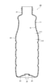
次に、図2を参照して、本実施形態に係る樹脂製の剥離容器20の構成例を説明する。図2は、本実施形態の剥離容器20の縦断面図である。
<Configuration example of peeling container>
Next, a configuration example of the
剥離容器20は、プリフォーム10を延伸ブロー成形することで得られるボトル形状の樹脂製容器であり、例えば、例えば醤油などの調味液が収容される。なお、剥離容器20の用途は、化粧品の化粧液やシャンプー(液状洗剤)または消毒・殺菌液(薬剤)など、他の内容物を収容するものでもよい。
The
剥離容器20は、プリフォーム10と同様に、第1層11の内側に第2層12が積層された二層構造を有している。剥離容器20の胴部22において、第2層12の厚さt12に対する第1層11の厚さt11の比(t11/t12)は、プリフォーム10の胴部14における厚さの比(t1/t2)とほぼ同様である。
The
剥離容器20は、上端に開口を有する首部21と、首部21から連続する円筒状の胴部22と、胴部22から連続する底部23とを有している。剥離容器20の製造においては、プリフォーム10の胴部14および底部15が延伸ブローで膨らむことで、剥離容器20の胴部22および底部23に賦形される。また、延伸ブローの際には、プリフォーム10の凹部17が延伸されることで、剥離容器20の底部23には第1層11を貫通する空気導入孔24が形成される。なお、首部21には、不図示の栓体が気密状態で係合される。栓体は、プッシュ式のポンプ機構または外気の流入を遮断/抑制する吐出機構を備えている。首部21に栓体を係合させることで、内容物の吐出時以外には、首部21から胴部22への外気の流入が抑制されて内容物の劣化(酸化)が抑制できる。さらに、栓体により、第1層11と第2層12との間にも首部21から外気が流入することもない。
The
剥離容器20においては、第2層12の内側の空間に内容物が充填される。剥離容器20では、第2層12から内容物が排出される際に空気導入孔24から第1層11と第2層12の間に徐々に空気が流入し、第1層11と第2層12が剥離していく。これにより、第2層12の内容物を空気に触れさせずに容器内で内容物の占める容積を空気に置き換えることができ、第2層12に充填された内容物を容器外に排出できる。さらに、剥離容器20では、第2層12の容積が内容物の消費に応じ自動的に小さくなり、内容物が少なくなったときは内容物を栓体のポンプ機構や吐出機構の側に集約させることが可能になる。そのため、剥離容器20では、吐出不能となる内容物の残量を最小限にすることができる。
In the peeling
また、剥離容器20の底部23の中心には、プリフォーム10と同様に第1層11を貫通する開口部25(非積層部25、単層部25)が形成されている。開口部25には第2層12の材料が開口部25を塞いで充填され、剥離容器20の底部23の開口部25近傍においては第1層11の外側に第2層12が露出した状態となっている。この第2層12の露出部(膨出部)は径方向の外側に向けて張り出しており、開口部25の直径より大きく形成されている。剥離容器20の露出部は、プリフォーム10の露出部が延伸されることで形成される。剥離容器20の開口部25において第2層12が第1層11の外側に露出することで第2層12が第1層11に部分的に固定(係止)され、第1層11に対する第2層12の位置ずれが抑止される。
In addition, an opening 25 (
<剥離容器の製造装置の説明>
図3は、本実施形態のブロー成形装置の構成を模式的に示す図である。本実施形態のブロー成形装置30は、容器の製造装置の一例であって、プリフォーム10を室温まで冷却せずに射出成形時の保有熱(内部熱量)を活用して剥離容器20をブロー成形するホットパリソン方式(1ステージ方式または1ステップ方式とも称する)を採用する。
<Description of the peeled container manufacturing device>
3 is a diagram showing a schematic configuration of a blow molding apparatus according to the present embodiment. The
ブロー成形装置30は、第1射出成形部31と、第1温度調整部32と、第2射出成形部33と、第2温度調整部34と、ブロー成形部35と、取り出し部36と、搬送機構37とを備える。第1射出成形部31、第1温度調整部32、第2射出成形部33、第2温度調整部34、ブロー成形部35および取り出し部36は、搬送機構37を中心として所定角度(例えば60度)ずつ回転した位置に配置されている。
The
(搬送機構37)
搬送機構37は、図3の紙面垂直方向の軸を中心に回転する回転板(移送板)37aを備える。回転板37aには、プリフォーム10の首部13(または剥離容器20の首部21)を保持するネック型37b(図3では不図示)が、所定角度ごとにそれぞれ1つ以上配置されている。搬送機構37は、回転板37aを回転させることで、ネック型37bで保持されたプリフォーム10(または剥離容器20)を、第1射出成形部31、第1温度調整部32、第2射出成形部33、第2温度調整部34、ブロー成形部35、取り出し部36の順に搬送する。なお、搬送機構37は、回転板37aを昇降させることもでき、第1射出成形部31や第2射出成形部33における型閉じや型開き(離型)に係る動作も行う。
(Transport mechanism 37)
The
(第1射出成形部31)
第1射出成形部31は、キャビティ型40、コア型41、ホットランナー型42を備え、成形時に搬送されるネック型37bと協働し、プリフォーム10の第1層11を製造する。キャビティ型40は、開口側(上方側)の第1のキャビティ型40Aと底面側(下方側)の第2のキャビティ型40Bから構成される。図3に示すように、第1射出成形部31には、ホットランナー型42に第1の樹脂材料を供給する第1射出装置38が接続されている。キャビティ型40とホットランナー型42は、一体化した状態で、ブロー成形装置30の機台に固定されている。コア型41は、コア型昇降機構に固定されている。
(First injection molding section 31)
The first
キャビティ型40は、第1層11の外周の形状を規定する。第1のキャビティ型40Aは、キャビティ型40の開口側に臨む金型であって、第1層11の胴部外周の形状を規定する。第2のキャビティ型40Bは、キャビティ型40の底面側に臨む金型であって、第1層11の底部外周の形状を規定する。また、ホットランナー型42は、第1射出装置38から第1の樹脂材料を導入する樹脂供給部42aを有する。コア型41は、第1層11の内周側の形状を規定する金型であって、キャビティ型40の内周側に上側から挿入される。ネック型37bはプリフォーム10(第1層11)の首部13の外形を規定する。図4では、キャビティ型40が第1のキャビティ型40Aと第2のキャビティ型40Bに分割されている例を示したが、キャビティ型40は分割されずに一体的に構成されていてもよい。
The
また、キャビティ型40のホットランナー型42は、コア型41に近接する位置まで軸方向に移動可能な不図示のバルブピン(樹脂供給部42aを開閉する棒状部材)を内部に有していてもよい。ホットランナー型42のバルブピンは、例えば、第1の樹脂材料が型空間に充填されるまではホットランナー型42の内部に収容され、第1の樹脂材料が型空間に充填された後、第2のキャビティ型40Bの底面よりもコア型41に近接する位置まで突出する。
The
図4に示すように、第1射出成形部31においては、上記のキャビティ型40、コア型41と、搬送機構37のネック型37bとを型閉じして第1層11の型空間を形成する。そして、上記の型空間の底部からホットランナー型42を介して第1の樹脂材料を流し込むことで、第1射出成形部31においてプリフォーム10の第1層11が製造される。なお、ホットランナー型42が上記のバルブピンを有する場合は、第1層11の型空間に第1の樹脂材料を流し込んだ後にバルブピンを上昇させ、第2のキャビティ型40Bの底面より突出しコア型41に近接する位置まで移動させてもよい。これにより、第1層11の底部中央を周辺部より肉厚の薄い薄膜状に成形できるため、後述する第1温度調整部32における開口部16の形成がより確実に行える。
As shown in FIG. 4, in the first
第1層11の底部外周に臨む第2のキャビティ型40Bの上面側には、所定位置に第1の突起部44が設けられている。例えば、第1の突起部44は、円柱形状、円錐状(テーパ円柱状)、角柱状、角錐状であって、樹脂供給部42aの位置する底部中央から径方向に間隔を空けて少なくとも1つ配置されている。
第1の突起部44の形状は、例えば軸方向に延長するリブ形状などの他の形状であってもよく、底部中央を基準として回転対称をなすように複数形成されていてもよい。また、第1の突起部44の数は、複数であってもよい。その際に、各々の第1の突起部44は中心軸を基準として点対称の位置関係で配置されていてもよい。
A
The shape of the
図4に示すように、第1層11の底部外周面(または第2のキャビティ型40Bのキャビティ基準面)からの第1の突起部44の突出量h1は、第1層11の厚さとほぼ同じ寸法である。そのため、第1射出成形部31を型閉じしたときには、第1の突起部44の先端はコア型41の表面に臨む(すなわち、第1の突起部44の先端はコア型41の表面近傍に配置される)。これにより、第1射出成形部31の射出成形においては、第1の突起部44により、プリフォーム10の凹部17に対応する位置に円形等の凹部11aが第1層11に形成される。第1層11の凹部11aは、第1層11を貫通していてもよく、コア型41と第1の突起部44に挟まれて形成された薄膜を有するものであってもよい。
As shown in FIG. 4, the protrusion amount h1 of the
また、第1射出成形部31の型開きをしたときにも、搬送機構37のネック型37bは開放されずにそのままプリフォーム10の第1層11を保持して搬送する。第1射出成形部31で同時に成形されるプリフォーム10の数(すなわち、ブロー成形装置30で同時に成形できる剥離容器20の数)は、適宜設定できる。なお、図3では、4つのプリフォームを同時に搬送する構成を示している。
In addition, even when the first
(第1温度調整部32)
第1温度調整部32は、後述する第1例の金型ユニット50aまたは第2例の金型ユニット50bのいずれかを備える。第1温度調整部32は、射出成形後の保有熱を備えた(高温状態にある)プリフォーム10の第1層11を、所定温度に保たれた金型ユニット50a,50bに収容することで温度調整する(第1層11が加熱または冷却される)。また、第1温度調整部32は、第2射出成形部33に搬送される前に、プリフォーム10の第1層11の温度分布を所定の状態に調整する機能も担う。
さらに、第1温度調整部32は、プリフォーム10の第1層11を金型ユニット50a,50bに収容する際に、第1層11の底部中心に開口部16を形成する。
(First temperature adjustment section 32)
The first
Furthermore, the first
図5は、第1温度調整部32の第1例の金型ユニット50aを示す図である。
第1例の金型ユニット50aは、キャビティ型(ポット型)51と、コア型52aと、可動型53aとを備える。
FIG. 5 is a diagram showing a
The
キャビティ型51は、第1射出成形部31で製造されたプリフォーム10の第1層11を収容可能な温調空間を有する金型である。キャビティ型51は、プリフォーム10の軸方向に沿って上下3段に分割された構成であり、上から順に、上段型51a、中段型51b、下段型51cを有する。キャビティ型51の下段型51cは、支持台56に載置されている。また、プリフォーム10の底部15に臨む下段型51cの底部中央と、支持台56には、可動型53aを挿通する空間が軸方向に沿って形成されている。
The
上段型51a、中段型51b、下段型51cのそれぞれには、ヒーターが設けられていたり、内部に温度調整媒体(冷却媒体)の流れる流路(不図示)が形成されていたりする。そのため、キャビティ型51の温度は、ヒーターや温度調整媒体により所定の温度に保たれる。なお、上段型51a、中段型51b、下段型51cのヒーターや温度調整媒体の温度を変更することで、プリフォーム10の温度分布を軸方向において変化させてもよい。なお、ヒーターが設けられたキャビティ型はプリフォーム10を非接触で加熱し、温度調整媒体の流路が設けられたキャビティ型はプリフォーム10に接触して温調または冷却を行う。
Each of the
コア型52aは、キャビティ型51に対して軸方向に移動可能な金型であって、キャビティ型51に収容される第1層11の内側に挿入される。コア型52aの内部には温度調整媒体(冷却媒体)の流れる流路(温調部材または冷却部材(不図示))が形成または内蔵され、上記の温度調整媒体によりコア型52aは所定の温度に保たれる。また、コア型52aの形状は、第1層11の内周面に対応する形状に形成されている。そのため、第1層11にコア型52aを挿入したときには、第1層の内周面はコア型52aの表面と面接触して両者の間で効率的に熱交換が行われる。
The
また、第1層11の底部15に臨むコア型52aの先端中心には、下側に向けて軸方向に突出する円錐形状の穿孔部(パンチングニードル)54が設けられている。穿孔部54は、コア型52aが第1層11に挿入されたときに第1層11の底部を貫通し、第1層11の底部中心に開口部16を形成する機能を担う。
In addition, a cone-shaped perforation section (punching needle) 54 that protrudes axially downward is provided at the center of the tip of the core die 52a facing the bottom 15 of the
可動型53aは、第1層11の底部中心に下側から臨む金型であって、下段型51cおよび支持台56に昇降可能に挿通される。可動型53aの表面には、コア型52aの穿孔部54の形状に対応し、型閉時に穿孔部54を受ける凹部55aが形成されている。
The
次に、図6を参照しつつ、第2例の金型ユニット50bの構成を説明する。第2例の金型ユニット50bの説明において、第1例の金型ユニット50aと同様の構成については同一符号を付して重複説明を省略する。
Next, the configuration of the
第2例の金型ユニット50bは、キャビティ型(ポット型)51と、コア型52bと、可動型53bとを備える。
The second
第2例の金型ユニット50bのコア型52bは、キャビティ型51に対して軸方向に移動可能な金型であって、キャビティ型51に収容される第1層11の内側に挿入される。コア型52bの内部には温度調整媒体(冷却媒体)の流れる流路(不図示)が形成または内蔵され、上記の温度調整媒体によりコア型52bは所定の温度に保たれる。また、コア型52bの形状は、第1層11の内周面に対応する形状に形成されている。そのため、第1層11にコア型52bを挿入したときには、第1層の内周面はコア型52bの表面と面接触して両者の間で効率的に熱交換が行われる。
また、第1層11の底部15に臨むコア型52bの先端中心には、可動型53bに設けられた後述の穿孔部54bの形状に対応し、型閉時に穿孔部54bを受ける凹部55bが形成されている。
The
In addition, a
可動型53bは、第1層11の底部中心に下側から臨む金型であって、下段型51cおよび支持台56に昇降可能に挿通される。可動型53bには、上側に向けて軸方向に突出する円錐形状の穿孔部54b(パンチングニードル)が設けられている。穿孔部54bは、可動型53bが上昇して型閉されたときに、コア型52bが挿入された状態の第1層11の底部15を貫通し、第1層11の底部中心に開口部16を形成する機能を担う。
The
また、図5、図6に示す金型ユニット50a、50bは、キャビティ型51からの放射熱(輻射熱)で第1層11を外側から加熱しつつ、温度調整媒体の流れるコア型52a、52bを接触させることで第1層11を内側から冷却している。
The
第2射出成形部33では、後述のように、第1層11の外側がキャビティ型60との接触により冷却されて温度が低下する。そのため、ブロー成形時にプリフォーム10が膨らみにくくなることを抑制するために、第1温度調整部32では外側から第1層11を加熱して保有熱を確保することが好ましい。
In the second
また、第2射出成形部33では、後述のように第1層11の内側が第2の樹脂材料で加熱されるため、第1層11の白化が生じやすくなる。そのため、第1温度調整部32では内側から第1層11を冷却して第1層11の白濁化(結晶化)を抑制することが好ましい。
In addition, in the second
(第2射出成形部33)
第2射出成形部33は、図7に示すように、キャビティ型60、コア型61、ホットランナー型62を備え、成形時に搬送されるネック型37bと協働し、第1層11の内周部に第2層12を射出成形する。キャビティ型60は、開口側(上方側)の第1のキャビティ型60Aと底面側(下方側)の第2のキャビティ型60Bから構成される。また、図3に示すように、第2射出成形部33には、ホットランナー型62に第2の樹脂材料を供給する第2射出装置39が接続されている。
(Second injection molding section 33)
As shown in FIG. 7, the second
キャビティ型60は、第1層11を収容する金型である。第1のキャビティ型60Aは、キャビティ型60の開口側に臨む金型であって、第1層11の胴部14を収容する。第2のキャビティ型60Bは、キャビティ型60の底面側に臨む金型であって、第1層11の底部15を収容する。また、ホットランナー型62は、第2射出装置39から第2の樹脂材料を導入する樹脂供給部62aを有する。コア型61は、第2層12の内周側の形状を規定する金型であって、キャビティ型60の内周側に上側から挿入される。ネック型37bはプリフォーム10(第2層12)の首部13の上部形状を規定する。なお、キャビティ型60は、第1のキャビティ型60Aと第2のキャビティ型60Bが分割されずに一体的に構成されていてもよい。
The
図7に示すように、第2射出成形部33は、第1射出成形部31で射出成形されたプリフォーム10の第1層11を収容する。第2射出成形部33を型閉じした状態では、第1層11の内周側と、コア型61の表面との間に型空間が形成される。第2射出成形部33においては、上記の型空間の底部からホットランナー型62を介して第2の樹脂材料を流し込むことで、第1層11の内周側に第2層12が積層されたプリフォーム10が形成される。
As shown in FIG. 7, the second
また、第1層11の底部外周に臨む第2のキャビティ型60Bの上面側には、第1射出成形部31の第1の突起部44と対応する所定位置に、プリフォーム10の凹部17の形状に対応した円柱状等の第2の突起部64が設けられている。第2の突起部64は、第2射出成形部33に第1層11が収容されたときに、第1層11の凹部11aに挿通される。
In addition, a
図7に示すように、第1層11の底部外周面(または第2のキャビティ型60Bのキャビティ基準面)からの第2の突起部64の突出量h2は、第1層11の厚さよりも大きい寸法である。つまり、第2の突起部64の突出量h2は、第1の突起部44の突出量h1よりも大きい(h2>h1)。そのため、第2射出成形部33を型閉じしたときには、第2の突起部64の先端は第1層11の凹部11aを貫通して第1層11の内周側まで突出する。第2射出成形部33の第2のキャビティ型60Bに第2の突起部64を設けることで、プリフォーム10の底部15に凹部17を形成することができる。
As shown in FIG. 7, the protrusion amount h2 of the
また、第2の突起部64の突出量h2は、プリフォーム10の厚さよりも小さく設定されている。つまり、第2射出成形部33での射出成形では、コア型61と第2の突起部64の間に第2の樹脂材料が流れ込むので、第2の突起部64により第2層12を貫通する孔は形成されない。
The protrusion amount h2 of the
なお、第2射出成形部33において、第1層11を収容するキャビティ型60の型空間の軸方向深さは、第1層11の軸方向長さよりも短くしてもよい。これにより、キャビティ型60に第1層11を収容したときに、第1層11の底部がキャビティ型60の底面に押し当てられて両者が接触し、第1層11の底部とキャビティ型60の間に隙間が生じることを抑制できる。また、第2層12が第1層11の開口部16から露出できるよう、第2のキャビティ型60Bの底部中央領域に凹部形状の成形空間を設け、底部中央領域において第1層11と第2のキャビティ型60Bとの間に僅かな隙間が形成されるようにしてもよい。
In the second
(第2温度調整部34)
第2温度調整部34は、第2射出成形部33で製造されたプリフォーム10の均温化や偏温除去を行い、プリフォーム10の温度を最終ブローに適した温度(例えば約90℃~105℃)に調整する。また、第2温度調整部34は、射出成形後の高温状態のプリフォーム10を冷却する機能も担う。さらに、第2温度調整部34はプリフォーム10を加熱する機能を有していてもよい。
(Second temperature adjustment section 34)
The second
(ブロー成形部35)
ブロー成形部35は、第2温度調整部34で温度調整されたプリフォーム10に対してブロー成形を行い、剥離容器20を製造する。
ブロー成形部35は、剥離容器20の形状に対応した一対の割型であるブローキャビティ型と、底型と、延伸ロッドおよびエア導入部材(いずれも不図示)を備える。ブロー成形部35は、プリフォーム10を延伸しながらブロー成形する。これにより、プリフォーム10がブローキャビティ型の形状に賦形されて剥離容器20を製造することができる。
(Blow molding section 35)
The
The
(取り出し部36)
取り出し部36は、ブロー成形部35で製造された剥離容器20の首部21をネック型37bから開放し、剥離容器20をブロー成形装置30の外部へ取り出すように構成されている。
(Removal section 36)
The
<容器の製造方法の説明>
次に、本実施形態のブロー成形装置30による剥離容器20の製造方法について説明する。図8は、容器20の製造方法の工程を示すフローチャートである。
<Explanation of container manufacturing method>
Next, a method for manufacturing the peeled
(ステップS101:第1射出成形工程)
まず、図4に示すように、第1射出成形部31において、キャビティ型40、コア型41および搬送機構37のネック型37bで形成された型空間に第1射出装置38から第1の樹脂材料が射出され、プリフォーム10の第1層11が成形される。このとき、第1の突起部44により、第1層11の底部には凹部11aが形成される。
(Step S101: First injection molding process)
4, in the first
その後、第1射出成形部31が型開きされると、搬送機構37の回転板37aが所定角度回転し、ネック型37bに保持されたプリフォーム10の第1層11が、射出成形時の保有熱を含んだ状態で第1温度調整部32に搬送される。
After that, when the first
(ステップS102:第1温度調整工程)
次に、第1温度調整部32において、第1例の金型ユニット50aまたは第2例の金型ユニット50bにプリフォーム10の第1層11が収容され、第1層11の冷却と温度分布の調整(均温化や偏温除去)が行われる。
(Step S102: First temperature adjustment step)
Next, in the first
第1例の金型ユニット50aが採用される場合、第1層11の内側にコア型52aを挿入するとコア型52aの先端に設けられた穿孔部54aが第1層11の底部15と接触する。このとき、可動型53aを第1層11に向けて上昇させると、第1層11がコア型52aに押し付けられることで穿孔部54aが第1層11の底部15を貫通し、第1層11の底部中心に開口部16が形成される。
When the first
第2例の金型ユニット50bが採用される場合、第1層11の内側にコア型52bを挿入するとコア型52bが第1層11の底部15の内面と接触する。このとき、可動型53bを第1層11に向けて上昇させると、可動型53bの穿孔部54aが第1層11の底部15を貫通し、第1層11の底部中心に開口部16が形成される。
When the second
また、第1温度調整部32での第1層11は射出成形時の保有熱を有し、比較的変形しやすい状態にある。そのため、第1層11に開口部16を形成すると、第1層11の底部中心にあった第1の樹脂材料は、穿孔部54a,54bに押しのけられて開口部16の周囲の材料と一体化する。したがって、本実施形態では、開口部16の形成の際に廃材を生じさせずに済む。
その後、搬送機構37の回転板37aが所定角度回転し、ネック型37bに保持されたプリフォーム10の第1層11が、第2射出成形部33に搬送される。
Furthermore, the
Thereafter, the rotating
(ステップS103:第2射出成形工程)
続いて、第2射出成形部33にプリフォーム10の第1層11が収容され、第2層12の射出成形が行われる。
第2射出成形部33においては、図7に示すように、第1層11の内周側と、第1層11の内周に臨むコア型61の表面との間に型空間が形成され、上記の型空間内にホットランナー型62から第2の樹脂材料を充填する。なお、射出成形のときには、第1層11の開口部16から第2の樹脂材料が第1層11の内周側に導かれる。
(Step S103: Second injection molding process)
Next, the
7, in the second
ここで、第2射出成形部33で充填する第2の樹脂材料の温度は、第1の樹脂材料の融点よりも低い温度に設定される。また、第2射出成形部33で第2の樹脂材料を充填するときの第1層11の表面温度は、第2の樹脂材料の融点以下の温度に冷却されている。
Here, the temperature of the second resin material filled in the second
第2射出成形部33では、第1層11の外周側にはキャビティ型60が臨み、キャビティ型60によって第1層11の形状が外周側から保持される。このため、第2の樹脂材料が第1層11と接触しても第1層11の熱変形を抑制できる。
In the second
また、第2射出成形部33では、第2の突起部64が第1層11の凹部11aを貫通して塞いでいるので、プリフォーム10の凹部17が第2の樹脂材料で塞がれることはない。また、第2射出成形部33における第2の突起部64は第1層の内周側まで先端が突出するので、第2の突起部64により形成されるプリフォーム10の凹部17は、第1層11を貫通して第2層12の表面が凹部17内に露出する形状となる。
In addition, in the second
また、第2射出成形部33において、第1層11を収容するキャビティ型60の型空間の軸方向深さは第1層11の軸方向長さよりも短い。そのため、第1層11の底部15がキャビティ型60の底面に押し当てられ、第1層11の底部15とキャビティ型60の間に隙間が生じることが抑制される。したがって、第1層11とキャビティ型60の間に第2の樹脂材料が流れ込みにくくなり、第2の樹脂材料が第1層11の外周を被覆する成形不良の発生が抑制される。
In addition, in the second
以上のようにして、第1射出成形工程および第2射出成形工程により、第1層11の内周側に第2層12が積層されたプリフォーム10が製造される。
その後、第2射出成形部33が型開きされると、搬送機構37の回転板37aが所定角度回転し、ネック型37bに保持されたプリフォーム10が、射出成形時の保有熱を含んだ状態で第2温度調整部34に搬送される。
In the manner described above, the
Thereafter, when the second
(ステップS104:第2温度調整工程)
続いて、第2温度調整部34にプリフォーム10が収容され、プリフォーム10の温度を最終ブローに適した温度に近づけるための温度調整が行われる。
その後、搬送機構37の回転板37aが所定角度回転し、ネック型37bに保持された温度調整後のプリフォーム10が、ブロー成形部35に搬送される。
(Step S104: Second temperature adjustment step)
Next, the
Thereafter, the rotating
(ステップS105:ブロー成形工程)
続いて、ブロー成形部35において、剥離容器20のブロー成形が行われる。
まず、ブローキャビティ型を型閉じしてプリフォーム10を型空間に収容し、エア導入部材(ブローコア)を下降させることで、プリフォーム10の首部13にエア導入部材が当接される。そして、延伸ロッドを降下させてプリフォーム10の底部15を内面から抑えて、必要に応じて縦軸延伸を行いつつ、エア導入部材からブローエアを供給することで、プリフォーム10を横軸延伸する。これにより、プリフォーム10は、ブローキャビティ型の型空間に密着するように膨出して賦形され、剥離容器20にブロー成形される。なお、プリフォーム10が剥離容器20より長い場合、底型は、ブローキャビティ型の型閉じ前はプリフォーム10の底部15と接触しない下方の位置で待機させ、型閉じ後に成形位置まで素早く上昇させる。
(Step S105: Blow molding process)
Next, in the
First, the blow cavity mold is closed to accommodate the
なお、本実施形態では、底部15に凹部17が形成されたプリフォーム10をブロー成形することで、剥離容器20において、第1層11を貫通し第2層12の表面まで至る空気導入孔24を確実に形成することができる。
In this embodiment, by blow molding a
(ステップS106:容器取り出し工程)
ブロー成形が終了すると、ブローキャビティ型が型開きされる。これにより、ブロー成形部35から剥離容器20が移動可能となる。
続いて、搬送機構37の回転板37aが所定角度回転し、剥離容器20が取り出し部36に搬送される。取り出し部36において、剥離容器20の首部21がネック型37bから開放され、剥離容器20がブロー成形装置30の外部へ取り出される。
(Step S106: container removal process)
When the blow molding is completed, the blow cavity mold is opened, which allows the peeling
Next, the
以上で、剥離容器20の製造方法における1つのサイクルが終了する。その後、搬送機構37の回転板37aを所定角度回転させることで、上記のS101からS106の各工程が繰り返される。なお、ブロー成形装置30の運転時には、1工程ずつの時間差を有する6組分の容器の製造が並列に実行される。
This completes one cycle in the manufacturing method for the peeled
また、ブロー成形装置30の構造上、第1射出成形工程、第1温度調整工程、第2射出成形工程、第2温度調整工程、ブロー成形工程および容器取り出し工程の各時間はそれぞれ同じ長さになる。同様に、各工程間の搬送時間もそれぞれ同じ長さになる。
In addition, due to the structure of the
以下、本実施形態のブロー成形装置およびブロー成形方法の効果を説明する。
本実施形態では、第1射出成形工程でプリフォーム10の第1層11(外層)を成形し、第2射出成形工程で第1層11の開口部16から第1層11の内側に第2層12(内層)を射出成形して二層構造のプリフォーム10が製造される。本実施形態によれば、融点の高い樹脂材料で外層を先に形成し、その後に外層よりも融点の低い樹脂材料で内層を形成できる。つまり、外層が射出成形時の保有熱を有する状態のまま内層の射出成形を連続的に行って、剥離容器20の仕様に適した二層構造のプリフォーム10を製造できる。本実施形態では、外層および内層がいずれも射出成形時の保有熱を有する状態で二層構造のプリフォーム10が離型されるので、ホットパリソン式のブロー成形法で剥離容器20を製造するときに好適なプリフォーム10を得ることができる。
The effects of the blow molding apparatus and the blow molding method of the present embodiment will be described below.
In this embodiment, the first layer 11 (outer layer) of the
そして、本実施形態では、射出成形時の保有熱を有する状態で、上記の二層構造のプリフォーム10を延伸ブロー成形して剥離容器20を製造する。そのため、本実施形態では、ホットパリソン式のブロー成形法によって、美的外観や物性強度等に優れた剥離容器20を製造できる。コールドパリソン式のブロー成形と比べると、本実施形態では製造されたプリフォーム10を常温近くまで冷却せずにすみ、プリフォーム10の再加熱の工程も不要となる。そのため、本実施形態によれば、プリフォーム10の射出成形から剥離容器20のブロー成形までの一連の工程を比較的短時間で完了させることができ、剥離容器20をより短いサイクルで製造できる。
In this embodiment, the above-mentioned two-
また、本実施形態では、第1射出成形工程と第2射出成形工程の間に第1温度調整工程を設け、この第1温度調整工程で第1層11に開口部16を形成する。第1温度調整工程を経ることで、第1射出成形工程での金型内での冷却時間を短縮できるとともに、第2層12を成形する前に第1層11の偏温を抑制できる。また、第1温度調整工程で第1層11に開口部16を形成することで、射出金型内に開口部16を形成する機構を組み込まずにすむので、射出成形装置の構成を簡素化することができる。
In addition, in this embodiment, a first temperature adjustment process is provided between the first injection molding process and the second injection molding process, and an
本発明は、上記実施形態に限定されることなく、本発明の趣旨を逸脱しない範囲において、種々の改良並びに設計の変更を行ってもよい。 The present invention is not limited to the above-described embodiment, and various improvements and design changes may be made without departing from the spirit of the present invention.
上記実施形態では、積層構造のプリフォームを用いたホットパリソン式のブロー成形法で剥離容器を製造する場合について説明した。しかし、本発明のブロー成形方法は、剥離容器の製造に限定されず、他の樹脂製容器の製造にも適用可能である。例えば、異なる色の樹脂材料を用いて外層、内層の順で射出成形を行ってグラデーションや色分け模様を有するプリフォームを成形し、ホットパリソン式のブロー成形法で樹脂製の装飾容器を製造する場合にも本発明を適用できる。 In the above embodiment, a case where a peelable container is manufactured by a hot parison type blow molding method using a preform with a laminated structure has been described. However, the blow molding method of the present invention is not limited to the manufacture of peelable containers, and can also be applied to the manufacture of other resin containers. For example, the present invention can be applied to a case where a preform with a gradation or color-coded pattern is molded by injection molding an outer layer and then an inner layer using resin materials of different colors, and a decorative resin container is manufactured by a hot parison type blow molding method.
加えて、今回開示された実施形態は、全ての点で例示であって制限的なものではないと考えられるべきである。本発明の範囲は、上記した説明ではなくて特許請求の範囲によって示され、特許請求の範囲と均等の意味及び範囲内での全ての変更が含まれることが意図される。例えば、ブロー成形装置30の成形ステーション数は適宜増減させてもよい(例えば第2温度調整部34や取り出し部36などを省略して5つにする、など)。また、金型ユニット50a、50bはブロー成形部35を備えない射出成形装置に搭載して剥離容器用プリフォームを成形する目的で利用してもよい。
In addition, the embodiments disclosed herein should be considered to be illustrative and not restrictive in all respects. The scope of the present invention is defined by the claims, not the above description, and is intended to include all modifications equivalent to the claims and within the scope of the claims. For example, the number of molding stations in the
10…プリフォーム、11…第1層、12…第2層、15…底部、16…開口部、20…剥離容器、30…ブロー成形装置、31…第1射出成形部、32…第1温度調整部、33…第2射出成形部、34…第2温度調整部、35…ブロー成形部、38…第1射出装置、39…第2射出装置、50a,50b…金型ユニット、51…キャビティ型、52a,52b…コア型、53a,53b…可動型、54a,54b…穿孔部、55a,55b…凹部
10...preform, 11...first layer, 12...second layer, 15...bottom, 16...opening, 20...peeling container, 30...blow molding device, 31...first injection molding section, 32...first temperature adjustment section, 33...second injection molding section, 34...second temperature adjustment section, 35...blow molding section, 38...first injection device, 39...second injection device, 50a, 50b...mold unit, 51...cavity mold, 52a, 52b...core mold, 53a, 53b...movable mold, 54a, 54b...perforation section, 55a, 55b...recess
Claims (4)
前記プリフォームの内部形状に対応する外形を有し、前記プリフォームの内部に挿入可能なコア金型と、
前記プリフォームを収容し、前記プリフォームの温度を調整するキャビティ型と、
前記プリフォームの底部に臨む可動部材と、を備え、
前記コア金型または前記可動部材のいずれかに、前記プリフォームの底部を貫通する開口を形成する穿孔部を有する
金型ユニット。 A mold unit that is applied to a manufacturing method of a hot parison type resin container, contains a bottomed resin preform having retained heat that has been released from an injection molding mold, and cools the preform,
a core mold having an outer shape corresponding to an internal shape of the preform and capable of being inserted into the preform;
a cavity mold for accommodating the preform and adjusting the temperature of the preform;
A movable member facing the bottom of the preform,
A mold unit having a perforation portion in either the core mold or the movable member that forms an opening through the bottom of the preform.
前記可動部材は、前記穿孔部を受ける凹部を有する
請求項1に記載の金型ユニット。 The perforated portion is formed to protrude from a tip of the core mold in an axial direction of the preform,
The mold unit according to claim 1 , wherein the movable member has a recess for receiving the perforation.
前記コア金型は、前記穿孔部を受ける凹部を有する
請求項1に記載の金型ユニット。 The perforated portion is formed in the movable member so as to protrude in an axial direction of the core die,
The die unit according to claim 1 , wherein the core die has a recess for receiving the perforation.
請求項1から請求項3のいずれか一項に記載の金型ユニットを有し、前記第1射出成形部で製造された前記第1層の温度調整を行うとともに、前記第1層の底部に開口部を形成する温度調整部と、
前記開口部から前記第1層の内周側に第2の樹脂材料を射出し、前記第1層の内周に第2層を積層する第2射出成形部と、
前記第2射出成形部で得られた多層のプリフォームを、射出成形時の保有熱を有する状態でブロー成形して樹脂製容器を製造するブロー成形部と、を備える
ブロー成形装置。
a first injection molding section for injection molding a first layer of a bottomed cylindrical preform with a first resin material;
a temperature adjustment section having the mold unit according to any one of claims 1 to 3, adjusting the temperature of the first layer produced in the first injection molding section and forming an opening in a bottom portion of the first layer;
a second injection molding unit that injects a second resin material from the opening onto an inner periphery side of the first layer and laminates a second layer on the inner periphery of the first layer;
a blow molding section that blow molds the multi-layer preform obtained in the second injection molding section while the multi-layer preform has the heat retained during injection molding to manufacture a resin container.
Applications Claiming Priority (4)
| Application Number | Priority Date | Filing Date | Title |
|---|---|---|---|
| JP2020131764 | 2020-08-03 | ||
| JP2020131764 | 2020-08-03 | ||
| PCT/JP2021/028666 WO2022030461A1 (en) | 2020-08-03 | 2021-08-02 | Resin container manufacturing method, die unit, and blow molding device |
| JP2022541546A JP7555417B2 (en) | 2020-08-03 | 2021-08-02 | Manufacturing method for resin container and blow molding device |
Related Parent Applications (1)
| Application Number | Title | Priority Date | Filing Date |
|---|---|---|---|
| JP2022541546A Division JP7555417B2 (en) | 2020-08-03 | 2021-08-02 | Manufacturing method for resin container and blow molding device |
Publications (2)
| Publication Number | Publication Date |
|---|---|
| JP2024166310A true JP2024166310A (en) | 2024-11-28 |
| JP7705994B2 JP7705994B2 (en) | 2025-07-10 |
Family
ID=80118049
Family Applications (2)
| Application Number | Title | Priority Date | Filing Date |
|---|---|---|---|
| JP2022541546A Active JP7555417B2 (en) | 2020-08-03 | 2021-08-02 | Manufacturing method for resin container and blow molding device |
| JP2024156554A Active JP7705994B2 (en) | 2020-08-03 | 2024-09-10 | Mold unit and blow molding device |
Family Applications Before (1)
| Application Number | Title | Priority Date | Filing Date |
|---|---|---|---|
| JP2022541546A Active JP7555417B2 (en) | 2020-08-03 | 2021-08-02 | Manufacturing method for resin container and blow molding device |
Country Status (5)
| Country | Link |
|---|---|
| US (1) | US20230321889A1 (en) |
| EP (1) | EP4190528A4 (en) |
| JP (2) | JP7555417B2 (en) |
| CN (1) | CN116323140A (en) |
| WO (1) | WO2022030461A1 (en) |
Families Citing this family (1)
| Publication number | Priority date | Publication date | Assignee | Title |
|---|---|---|---|---|
| EP4190528A4 (en) * | 2020-08-03 | 2024-09-18 | Nissei ASB Machine Co., Ltd. | METHOD FOR MANUFACTURING RESIN CONTAINER, DIE UNIT AND BLOW MOLDING DEVICE |
Citations (7)
| Publication number | Priority date | Publication date | Assignee | Title |
|---|---|---|---|---|
| JPH0382522A (en) * | 1989-08-25 | 1991-04-08 | Dainippon Printing Co Ltd | Method and device for molding bottle with hole |
| JPH06263133A (en) * | 1993-03-11 | 1994-09-20 | Nissei Asb Mach Co Ltd | Refillable container of polypropylene for drinking water and method for manufacture |
| JP2001105477A (en) * | 1999-10-08 | 2001-04-17 | Taisei Kako Co Ltd | Method for producing laminated release container, apparatus for producing parison for blow molding of laminated release container, and method for forming holes only in outer layer of laminated injection molded article |
| JP2001105478A (en) * | 1999-10-08 | 2001-04-17 | Taisei Kako Co Ltd | Method for producing laminated bottle and production apparatus for laminated release container |
| WO2001026881A1 (en) * | 1999-10-08 | 2001-04-19 | Taisei Kako Co., Ltd. | Method of producing laminated bottles having peelable inner layer |
| JP2002104362A (en) * | 2000-09-29 | 2002-04-10 | Taisei Kako Co Ltd | Laminated resin bottle and manufacturing method for laminated resin molded product |
| WO2022030461A1 (en) * | 2020-08-03 | 2022-02-10 | 日精エー・エス・ビー機械株式会社 | Resin container manufacturing method, die unit, and blow molding device |
Family Cites Families (9)
| Publication number | Priority date | Publication date | Assignee | Title |
|---|---|---|---|---|
| JP2931428B2 (en) * | 1990-03-30 | 1999-08-09 | 株式会社青木固研究所 | Injection stretch blow molding method |
| JP2000043126A (en) * | 1998-07-31 | 2000-02-15 | Toppan Printing Co Ltd | Two-layer preform for stretch blow molding |
| JP4357183B2 (en) * | 2003-02-14 | 2009-11-04 | 大成化工株式会社 | Delaminated bottle and method for producing the same |
| WO2008125698A1 (en) * | 2007-04-11 | 2008-10-23 | Molmasa Aplicaciones Técnicas, S.L. | Mould and method for manufacturing bicomponent preforms by overmoulding, and thus obtained bicomponent preform |
| JP5267901B2 (en) | 2007-06-29 | 2013-08-21 | 株式会社吉野工業所 | Synthetic resin double container by direct blow molding method |
| JP5697885B2 (en) * | 2009-09-11 | 2015-04-08 | 日精エー・エス・ビー機械株式会社 | Blow molding machine |
| CN121733792A (en) * | 2017-10-19 | 2026-03-27 | 日精Asb机械株式会社 | Method for manufacturing resin container, mold unit, and molding machine |
| WO2019075702A1 (en) * | 2017-10-19 | 2019-04-25 | Tencent Technology (Shenzhen) Company Limited | Methods and systems for processing graphics |
| WO2020138292A1 (en) * | 2018-12-28 | 2020-07-02 | 日精エー・エス・ビー機械株式会社 | Blow molding device, blow molding method, and mold unit |
-
2021
- 2021-08-02 EP EP21852928.7A patent/EP4190528A4/en active Pending
- 2021-08-02 WO PCT/JP2021/028666 patent/WO2022030461A1/en not_active Ceased
- 2021-08-02 JP JP2022541546A patent/JP7555417B2/en active Active
- 2021-08-02 US US18/019,157 patent/US20230321889A1/en active Pending
- 2021-08-02 CN CN202180063227.9A patent/CN116323140A/en active Pending
-
2024
- 2024-09-10 JP JP2024156554A patent/JP7705994B2/en active Active
Patent Citations (7)
| Publication number | Priority date | Publication date | Assignee | Title |
|---|---|---|---|---|
| JPH0382522A (en) * | 1989-08-25 | 1991-04-08 | Dainippon Printing Co Ltd | Method and device for molding bottle with hole |
| JPH06263133A (en) * | 1993-03-11 | 1994-09-20 | Nissei Asb Mach Co Ltd | Refillable container of polypropylene for drinking water and method for manufacture |
| JP2001105477A (en) * | 1999-10-08 | 2001-04-17 | Taisei Kako Co Ltd | Method for producing laminated release container, apparatus for producing parison for blow molding of laminated release container, and method for forming holes only in outer layer of laminated injection molded article |
| JP2001105478A (en) * | 1999-10-08 | 2001-04-17 | Taisei Kako Co Ltd | Method for producing laminated bottle and production apparatus for laminated release container |
| WO2001026881A1 (en) * | 1999-10-08 | 2001-04-19 | Taisei Kako Co., Ltd. | Method of producing laminated bottles having peelable inner layer |
| JP2002104362A (en) * | 2000-09-29 | 2002-04-10 | Taisei Kako Co Ltd | Laminated resin bottle and manufacturing method for laminated resin molded product |
| WO2022030461A1 (en) * | 2020-08-03 | 2022-02-10 | 日精エー・エス・ビー機械株式会社 | Resin container manufacturing method, die unit, and blow molding device |
Also Published As
| Publication number | Publication date |
|---|---|
| JPWO2022030461A1 (en) | 2022-02-10 |
| JP7555417B2 (en) | 2024-09-24 |
| JP7705994B2 (en) | 2025-07-10 |
| EP4190528A1 (en) | 2023-06-07 |
| WO2022030461A1 (en) | 2022-02-10 |
| EP4190528A4 (en) | 2024-09-18 |
| CN116323140A (en) | 2023-06-23 |
| US20230321889A1 (en) | 2023-10-12 |
Similar Documents
| Publication | Publication Date | Title |
|---|---|---|
| JP7705994B2 (en) | Mold unit and blow molding device | |
| JP7353471B2 (en) | Manufacturing method and manufacturing device for peelable containers | |
| WO2024101420A1 (en) | Peelable container, preform, and manufacturing method and manufacturing device for peelable container | |
| WO2019146701A1 (en) | Manufacturing method of a plastic container component, mold unit, and blow molding machine provided with mold unit | |
| JP7524312B2 (en) | Peeling container and method for manufacturing the same | |
| JP7536847B2 (en) | Container manufacturing method and blow molding device | |
| JP7642892B2 (en) | Method and device for manufacturing peeling container | |
| EP4257330B1 (en) | Method and apparatus for manufacturing resin container | |
| WO2024225433A1 (en) | Separable container, and separable container production method and production device | |
| WO2023171603A1 (en) | Resin container manufacturing method, mold unit for temperature adjustment, and resin container manufacturing apparatus | |
| CN114981066A (en) | Method and apparatus for manufacturing resin container, and mold assembly |
Legal Events
| Date | Code | Title | Description |
|---|---|---|---|
| A621 | Written request for application examination |
Free format text: JAPANESE INTERMEDIATE CODE: A621 Effective date: 20240910 |
|
| TRDD | Decision of grant or rejection written | ||
| A977 | Report on retrieval |
Free format text: JAPANESE INTERMEDIATE CODE: A971007 Effective date: 20250528 |
|
| A01 | Written decision to grant a patent or to grant a registration (utility model) |
Free format text: JAPANESE INTERMEDIATE CODE: A01 Effective date: 20250603 |
|
| A61 | First payment of annual fees (during grant procedure) |
Free format text: JAPANESE INTERMEDIATE CODE: A61 Effective date: 20250630 |
|
| R150 | Certificate of patent or registration of utility model |
Ref document number: 7705994 Country of ref document: JP Free format text: JAPANESE INTERMEDIATE CODE: R150 |