JP2023020958A - Device for adjusting length of bracelet - Google Patents
Device for adjusting length of bracelet Download PDFInfo
- Publication number
- JP2023020958A JP2023020958A JP2022113920A JP2022113920A JP2023020958A JP 2023020958 A JP2023020958 A JP 2023020958A JP 2022113920 A JP2022113920 A JP 2022113920A JP 2022113920 A JP2022113920 A JP 2022113920A JP 2023020958 A JP2023020958 A JP 2023020958A
- Authority
- JP
- Japan
- Prior art keywords
- adjusting
- cover
- bracelet
- length
- actuator
- Prior art date
- Legal status (The legal status is an assumption and is not a legal conclusion. Google has not performed a legal analysis and makes no representation as to the accuracy of the status listed.)
- Pending
Links
- 238000006073 displacement reaction Methods 0.000 claims abstract description 30
- 230000000694 effects Effects 0.000 claims description 7
- 230000008878 coupling Effects 0.000 claims description 6
- 238000010168 coupling process Methods 0.000 claims description 6
- 238000005859 coupling reaction Methods 0.000 claims description 6
- 238000006243 chemical reaction Methods 0.000 description 16
- 238000000034 method Methods 0.000 description 11
- 230000008569 process Effects 0.000 description 11
- 239000011295 pitch Substances 0.000 description 6
- 230000000630 rising effect Effects 0.000 description 2
- 238000004904 shortening Methods 0.000 description 2
- 230000002463 transducing effect Effects 0.000 description 2
- 230000008859 change Effects 0.000 description 1
- 230000000295 complement effect Effects 0.000 description 1
- 238000010276 construction Methods 0.000 description 1
- 230000009467 reduction Effects 0.000 description 1
- 230000000284 resting effect Effects 0.000 description 1
- 230000003068 static effect Effects 0.000 description 1
- 230000001131 transforming effect Effects 0.000 description 1
- 210000000707 wrist Anatomy 0.000 description 1
Images


Classifications
-
- A—HUMAN NECESSITIES
- A44—HABERDASHERY; JEWELLERY
- A44C—PERSONAL ADORNMENTS, e.g. JEWELLERY; COINS
- A44C5/00—Bracelets; Wrist-watch straps; Fastenings for bracelets or wrist-watch straps
- A44C5/18—Fasteners for straps, chains or the like
- A44C5/22—Fasteners for straps, chains or the like for closed straps
- A44C5/24—Fasteners for straps, chains or the like for closed straps with folding devices
- A44C5/246—Fasteners for straps, chains or the like for closed straps with folding devices having size adjusting means
Landscapes
- Buckles (AREA)
- Measuring Pulse, Heart Rate, Blood Pressure Or Blood Flow (AREA)
Abstract
Description
本発明は、ブレスレットの長さを調節するための装置に関し、特にブレスレットの二つの端の間に設けられた展開留め金を有する腕時計に適したものに関する。本発明はまた、上述したようなブレスレットの長さを調節するための装置を採用する留め金及びブレスレット自体に関し、及び上述したような装置を含む小型時計、例えば腕時計自体に関する。 The present invention relates to a device for adjusting the length of a bracelet, particularly suitable for watches having a deployment clasp provided between two ends of the bracelet. The invention also relates to a clasp and the bracelet itself employing a device for adjusting the length of a bracelet as described above, and to a small timepiece, eg a wristwatch itself, including a device as described above.
従来技術に基づく、装着者の腕の周りに時計のブレスレットの二つの鎖を留めるために設けられた展開留め金は、ブレードが互いに重なり合うよう折りたたまれた第1の、閉位置と、各ブレードが重なりあうことなく展開されることにより時計を装着及び取り外し可能とする第2の、開位置と、を占めることが可能な、複数の連接式ブレードを含む。このような留め金は一般的に、ブレスレットの及びまたはブレスレット鎖の長さを調節するための手段を有する。 A prior art deployment clasp provided for fastening two chains of a watch bracelet around the arm of the wearer has a first, closed position in which the blades are folded over one another and each blade is It includes a plurality of articulated blades that can occupy a second, open position that allows the watch to be worn and removed by being unfolded without overlapping. Such clasps generally have means for adjusting the length of the bracelet and/or the bracelet chain.
そのため、既存の留め金は、ブレスレットの長さを一回または複数回調節することを可能とする解決策を有する。例として、特許文献1、2および3は、ブレスレットの長さを調節する解決策であって、ブレスレットの調節リンク要素が当該ブレスレットの留め金のカバーに対して変位可能であるものを開示する。これら既存の解決策は、一般的に、ブレスレットの長さを調整する際に、ユーザが可動要素を適切に配置するという特定の操作を行うことを必要とする。 Therefore, existing clasps have solutions that allow the bracelet length to be adjusted once or multiple times. By way of example, US Pat. Nos. 6,001,000, 6,000,000 and 6,000,000 disclose solutions for adjusting the length of a bracelet, in which the adjustment link elements of the bracelet are displaceable with respect to the cover of the clasp of the bracelet. These existing solutions generally require the user to perform certain manipulations to properly position the movable elements when adjusting the length of the bracelet.
本発明の概括的な目的は、ブレスレットの長さの調節性をさらに向上させることである。 A general object of the invention is to further improve the adjustability of the length of the bracelet.
より詳細には、本発明の目的は、動作に信頼性があり、操作が直感的で便利である、ブレスレットの長さを調節するための解決策を提案することである。以下に示す本発明の利点は、特に、腕から時計を取り外すことを必要とすることなく調節可能である事実に由来する。 More particularly, the object of the invention is to propose a solution for adjusting the length of the bracelet, which is reliable in operation, intuitive and convenient to operate. The following advantages of the invention stem in particular from the fact that it can be adjusted without having to remove the watch from the wrist.
加えて、本発明の目的は、特に審美的な目的で、それが取り付けられたブレスレットまたは留め金に対して最適に組み込まれている、ブレスレットの長さを調節するための解決策を提案することである。 In addition, it is an object of the present invention to propose a solution for adjusting the length of a bracelet, especially for aesthetic purposes, which is optimally integrated to the bracelet or clasp to which it is attached. is.
そのため、本発明はブレスレットの長さを調節するための装置に基づき、その調節リンク要素は、ブレスレットを伸ばすまたは縮めるためにブレスレット鎖の一端を駆動するよう、カバーに対して長手方向に移動可能なように取り付けられ、当該調節リンク要素は、長手方向に移動可能なようにカバーの表面に取り付けられ、第一運動学的連結を介して調節リンク用に接続された、作動装置の作動により変位される。 Therefore, the invention is based on a device for adjusting the length of a bracelet, the adjusting link element of which is longitudinally displaceable relative to the cover to drive one end of the bracelet chain to extend or shorten the bracelet. , wherein the adjusting link element is displaced by actuation of an actuating device mounted for longitudinal movement on the surface of the cover and connected for the adjusting link via a first kinematic connection. be.
本発明は、請求項によってより詳細に定義される。 The invention is defined in more detail by the claims.
本発明のこれら目的、特徴及び有利点は、添付の図面を参照しつつ、以下に示す特定の実施形態についての非限定的な説明においてより詳細に開示される。 These objects, features and advantages of the present invention are disclosed in more detail in the following non-limiting description of specific embodiments with reference to the accompanying drawings.
以下の説明を簡単にするため、「長手方向」とは、ブレスレットまたはブレスレット鎖の長さに関連して定義され使用される。この定義は、調節装置及び留め金自体に対しても、当該調節装置または当該留め金が接続されるブレスレット鎖の長手方向を考慮して、解釈される。 For ease of discussion below, "longitudinal" is defined and used in relation to the length of the bracelet or bracelet chain. This definition is also interpreted for the adjustment device and the clasp itself, taking into account the longitudinal direction of the bracelet chain to which the adjustment device or the clasp is connected.
加えて、「上」という形容詞は、ブレスレットが装着された際、ユーザの腕から離れた配置を取り続けるよう意図される表面またはあらゆる部分を指すと定義され使用される。例えば、留め金のカバーの上面は、留め金が腕に対して閉じた際に、腕に向かって配置され隠された表面とは離れて、ユーザが見ることのできる表面である。 Additionally, the adjective "top" is defined and used to refer to a surface or any part intended to remain in a displaced configuration from the user's arm when the bracelet is worn. For example, the top surface of the clasp cover is the surface visible to the user when the clasp is closed against the arm, apart from the hidden surface positioned toward the arm.
「垂直方向」とは、ユーザの腕に対して接することを意図される領域から反対側の領域に向かう、長手方向に直角な方向と定義される。そのため、当該方向は、後述する説明から明らかになる通り、例えばカバーの上面に直角または実質的に直角である。 "Vertical" is defined as the direction perpendicular to the longitudinal direction from the area intended to contact the user's arm to the opposite area. Therefore, the direction is, for example, perpendicular or substantially perpendicular to the upper surface of the cover, as will become apparent from the description below.
最後に、「横方向」とは、長手方向と垂直方向の二つの方向に対して直角な方向であると定義される。 Finally, "lateral" is defined as the direction perpendicular to the two directions, the longitudinal direction and the vertical direction.
説明を簡単にするため、以下に説明される二つの実施形態における同一の符号は、同一の部品、または類似の、または同等の部品を示すのに使用される。 For ease of explanation, the same reference numerals in the two embodiments described below are used to denote identical or similar or equivalent parts.
本発明の第一実施形態に係る、ブレスレットの長さを調節するための装置を、図1から9を参照しつつ、以下に説明する。 A device for adjusting the length of a bracelet according to a first embodiment of the invention will now be described with reference to FIGS.
当該実施形態によると、ブレスレットの長さを調節するための装置は、互いに連接された二つのブレード2、3を含む留め金1の中に配置される。そのため、第二ブレード3はその二つの端部がそれぞれ、第一ブレード2及びカバー10の第一部分4に、それぞれ第一回転ピン5及び第二回転ピン6を介して連接される。第一ブレード2は、第一ブレスレット鎖7とカバー8の第二部分とに固定するための、第二ブレード3の連結とは反対の端に配置された、装置を含む。カバー10は、以下に詳述するブレスレットの長さを調節するための装置を含む。既知の方法によって、留め金1は、二つのブレードが重なり合った状態で折りたたまれ、その位置に、特にカバーを介して係止され、ブレスレットがユーザによって装着された閉鎖構造、及び、ブレードが展開され、ブレスレットを腕から取り外すことを可能とする開放構造を占めることができる。図1は、留め金が展開途中の中間位置にある状態を示す。
According to this embodiment, the device for adjusting the length of the bracelet is arranged in a
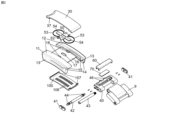
図2は、当該第一実施形態に係るブレスレットの長さを調節するための装置をより詳細に示す、分解斜視図である。当該調節装置は、より詳細には、留め金1のカバー10内に配置される。
Figure 2 is an exploded perspective view showing in more detail the device for adjusting the length of the bracelet according to the first embodiment; Said adjustment device is more particularly arranged in the
カバー10は、垂直長手正中面に対して対称的な二つの側面部分を含む、本体11を含む。側面部分はそれぞれ、上面部分12及び上面部分12に実質的に直角な側壁13を含む。長手溝14が各側壁13の内側面に配置される。有利には角形断面形状を有する歯列の形を取る、割出し及び係止要素15が、これらの溝14内に追加的に配置される。当該歯列は鉛直長手面に延びる。高さの中間または実施的に中間において、中間基部16がカバー10の二つの側面部分を連結する。中間基部16は中央開口17を含む横板の形状を取る。
The
ブレスレットの長さを調節するための装置は、第一運動学的連結を介して調節リンク要素40に接続された作動装置30を含む。
A device for adjusting the length of the bracelet includes an
作動装置30は、カバー10に対して長手方向に移動可能な面の形状を取る。この面は、カバー10を補完するためにその上面に配置されて、上面部分12を補完し、それにより、従来からの既知の他の留め金と類似の外観を有する実質的に連続した面を形成する。
調節リンク要素40は、カバーに関する調節リンク要素40の長手方向の変位を許容するため、カバー10の各長手溝14の中にそれぞれ配置される二つの側面キャップ41を含む。当該実施形態において、これら二つのキャップ41はそれぞれ横断ロッド42の二つの端に配置される。調節リンク要素40は追加的に、ブレスレット鎖のための固定装置を含む。この実施形態において、当該固定装置は、その周りに第二ブレスレット鎖9の第一リンク要素が取り付けられた、ピン43の形を取る。調節リンク要素40は追加的に、それが長手方向に駆動されることを許容することを意図される、少なくとも一つの駆動戻り止め46を含む。当該実施形態においては、二つの実質的に垂直な駆動戻り止め46を含む。そのため、その長手方向への変位によって、調節リンク要素40は当該長手方向に第二ブレスレット鎖9を駆動可能であり、それにより、第二ブレスレット鎖9の長さ及びより一般的にはブレスレットの長さを調整することを可能とする。
The
第一運動学的連結は作動装置30を調節リンク要素40に接続することを可能とすることにより、作動装置30の作動により調節リンク要素40を駆動することを可能とする。この作動について以下に詳細に説明する。
The first kinematic connection allows the
当該第一運動学的連結は、作動装置30の下面とカバー10の基部16との間に設けられた第一特定ばねの形を取る、第一弾性戻し要素50を含む。当該実施形態において、この第一ばねは、一方では長手方向の双方向に、他方では垂直方向に、作動装置30の複数の弾性戻し力を発揮するよう設計される。そのため、第一ばねは、切り取られ、カバー10の基部16に形成された二つの突出部18によって中央部分に囲い込まれた、ばねの形を取る。第一ばねは、基部16の中央開口17に実質的に重なる中央開口52を含む。第一ばねは追加的に、ばねの本体の断面より小さな断面を有する二つの円形に湾曲された弾性部分53を含み、それにより上述した様々な方向への戻し機能を実施する。さらに、当該第一ばねはさらに、同じように作動装置30の垂直方向における弾性戻しに貢献する、二つの別の延長湾曲可撓部分54を含む。当該第一弾性戻し要素50はより詳細には、作動装置30をその静止位置に、好ましくは基部16の中央に並んだ状態で、より一般的にはカバー10に対して、戻し保持することを可能とする。第一運動学的連結は追加的に、長手方向に均等に並んだ孔106の形を取る戻り止めシステムを含む平面板の形を取るラック100、及び二つの駆動戻り止め46を含む。本実施形態において、戻り止めシステムは、二つの駆動戻り止め46の間隔に対応して配置される二つの平行した連続の孔106を含む。二つの長手端において、ラック100は、ラックに実質的に直角な上向き傾斜部107を含み、それらは作動装置の対応する結合部37に固定されるように、作動装置30に向かって立ち上がる。この結合は、作動装置30の動きに連動してラック100が長手方向に移動可能であるという効果を有する。
Said first kinematic connection comprises a first
この実施例において、ブレスレットの長さを調節するための装置は追加的に、二つの構成を占めることができる係止装置を含む。二つの構成とは、カバー10に対する変位を防止するよう調節リンク要素40に作用する第一の、係止構成と、調節を有効とする目的で、調節リンク要素40を解放することにより、カバー10に対して移動可能とする係止解除構成である。この実施例において、当該係止装置は、調節リンク要素の横断ロッド42の二つの端にそれぞれ配置された、好ましくは角形断面形状を有する、係止戻り止め44によって実現され、係止戻り止め44は長手溝14内に配置された割出し及び係止要素15と協働するよう設計される。ロッド42は有利にはばね棒の形状を取る。本実施形態において、係止装置は作動装置30によって作動される。
In this embodiment, the device for adjusting the length of the bracelet additionally comprises a locking device that can occupy two configurations. The two configurations are a first, locking configuration which acts on the
係止装置は追加的に、作動装置30を係止装置に連結する第二の運動学的連結を含み、それにより作動装置30の作動を介して係止及び係止解除が可能となる。当該第二の運動学的連結は、中間要素60と、その幅全体にわたって変形、特にその凸形状が変化することを意図される、平面状のまたは実質的に平面状のばね板の形を取る第二弾性戻り要素70とを含む。ロッド42を形成するばね棒は、中間要素60に対してばね板によって弾性的に戻り、係止戻り止め44を二つの割出し及び係止要素15の間に位置させることにより、係止装置をその係止構成に位置させる。押しボタンの形を取る中間要素60も同様に、垂直方向に変位可能である。中間要素60は、ばね棒を下向きに変位するよう第二弾性戻り要素70に対して作動するよう意図され、それにより割出し及び係止要素15の係止戻り止め44を解除する(図6)。
The locking device additionally includes a second kinematic connection connecting the
このブレスレットの長さを調節するための装置の動作について、図3から10を参照しつつ説明する。 The operation of this device for adjusting the length of the bracelet will now be described with reference to FIGS.
図3及び図4は、ブレスレットの長さを調節するための装置の、垂直長手正中面を通る断面図である。 3 and 4 are cross-sectional views through the vertical longitudinal median plane of the device for adjusting the length of the bracelet.
図3は、係止構成において静止した、調節装置を示す。要素の係止戻り止め44は二つの割出し及び係止要素15の間に位置され、駆動戻り止め46はラック100内の孔106から係合解除されている。図4は、係止解除構成にある調節装置を示す。作動装置30がその上面31に対する簡単な中央への接触により、下向きの垂直な圧力によって作動されたことがわかる。この圧力は、基部16に対して第一弾性戻し要素50を形成する第一ばねを圧縮する効果を有する。この作動により、ラック100の戻り止めシステムは駆動戻り止め46と係合される。より詳細には、これらの駆動戻り止め46はラック100の孔106内に位置される。同時に、ラック100は接触を中間要素60に伝え、中間要素60は同様に接触をロッド42に伝え、それによりロッド42は第二弾性戻り要素70に接して下向きに変位し、第二弾性戻り要素70は変形する。ロッド42は、その係止戻り止め44が割出し及び係止要素15から外れるよう、垂直に変位する。このように、調節リンク要素40はもはや係止されておらず、長手方向に変位するよう作動可能となる。調節装置はそれにより係止解除構成を取る。
FIG. 3 shows the adjustment device stationary in the locked configuration.
調節装置の作用の明確な理解のため、ブレスレットを縮める元となる調節装置の様々な構成を示す断面斜視図である図5から図9を参照しつつ、ブレスレットを縮める作業について説明する。 For a clear understanding of the operation of the adjuster, the operation of shortening the bracelet will be described with reference to FIGS.
図5は、上記で説明した図3と同じ構成にある、静止した状態の調節装置を示す。ラック100が調節リンク要素40の駆動戻り止め46と係合していないことがわかる。加えて、係止戻り止め44は割出し及び係止要素15と係合され、調節リンク要素40をその長手方向位置に係止し、それによりブレスレットの長さを調節するための装置を係止する。第一弾性戻し要素50が作動装置30をその静止位置に安定的に保持しているため、この静止位置は安定している。
FIG. 5 shows the adjustment device at rest, in the same configuration as in FIG. 3 described above. It can be seen that
図6は、図4に示される位置と同様の、ブレスレットの長さを調節するための装置がその係止解除構成にある、中間調節位置を示す。この構成において、図4に関して説明されたとおり、作動装置30は下向きに駆動される。
FIG. 6 shows an intermediate adjustment position, similar to the position shown in FIG. 4, in which the device for adjusting the length of the bracelet is in its unlocked configuration. In this configuration,
図7は、ブレスレットの長さを縮めるよう長さ調節を実施することを示す。作動装置30に対する下向きの垂直圧力が維持され、作動装置30は長手方向に、図7における左向きに、変位する。これらの作動により、第一運動学的連結を介して調節リンク要素40が同じ長手方向変位をするよう駆動される。
FIG. 7 illustrates making length adjustments to reduce the length of the bracelet. A downward vertical pressure on the
有利には、作動装置30の長手方向への移動は、一つ以上の止め部により制限される。この実施形態において、当該移動は基部16の中央開口17の長さにより定義され、中央開口17は作動装置30の突起33の変位に対する止め部を形成する。この作動装置30の最大長手方向移動は、有利には、調節リンク要素40を、連続する二つの割出し及び係止要素15の間のピッチに対応する1ピッチまたは数ピッチずつスライド可能なように提供される。これにより、ブレスレットの長さ調節は、その静止位置から長手方向の止め部に達するまでの、作動装置30の直進運動または連続直進運動に対応可能である。加えて、好ましくは、ラック100のピッチ、言い換えるなら二つの孔106の間のピッチは、二つの割出し及び係止要素15の間のピッチと同一である。この配置は、係止戻り止め44が割出し及び係止要素15のために提供されるケーシングに面する際に、ラック100の孔106に駆動戻り止め46が常に面するよう設計される。
Advantageously, longitudinal movement of
長さ調節の後、ユーザは作動装置30への圧力を緩める。二つの弾性戻し要素50、70の二重弾性戻りにより、作動装置30及び第一、第二運動学的連結の各要素は垂直方向に立ち上がる。調節リンク要素の係止戻り止め44も、ロッド42の立ち上がりの効果により、同様に立ち上がり、二つの割出し及び係止要素15の間に収容される。この新しい構成により、ラック100はその頂点位置にあり、調節リンク要素40の駆動戻り止め46の範囲外にあることを注記する。図8は、当該構成にある装置を示す。
After adjusting the length, the user releases pressure on
最後に、ユーザは完全に作動装置30を解放し、それにより作動装置30は第一弾性戻し要素50、つまり第一ばねによって与えられた戻り力によってその初期静止位置に戻る。特に、図8に関して説明されたその立ち上がりのほかに、作動装置30はさらに、第一バネの垂直方向及び長手方向の二つの方向における弾性戻りによって、好ましくは中央において、長手方向における静止位置を再度取る。図9はこの静止構成を示す。
Finally, the user completely releases the
当該ブレスレットの使用可能長さを増加させることからなる調節は、当然、作動装置30を長手方向の反対側、つまり図5から図9における右側に向かって変位することにより類似した方法で実施可能である。
An adjustment consisting in increasing the usable length of the bracelet can of course be carried out in a similar way by displacing the
調節リンク要素40は、カバー10内の溝14の中の端部位置に達した際にそれに当接し、長手方向の一方向にのみ変位可能となることを注記する。
Note that the adjusting
また、同じ構成により、作動装置30を長手方向にスライドさせることによって開始され、その後垂直方向の圧力をかけることにより装置を係止解除して調節リンク要素を係合させ、その後作動装置がその初期位置に戻るまでこの接触を維持する、ブレスレットの使用可能長さの調節の実施が可能であることを注記する。その結果、作動装置がその初期位置に戻る際に、調節リンク要素は並進移動される。
The same arrangement also allows the
実施形態の一変形例において、作動装置は、上述の実施形態における長手方向と垂直方向の移動の代わりに、長手方向及び横方向の二つの変位によって移動可能なように設計されてよい。第一運動学的連結はそのような実施のために変更される。 In one variant of the embodiment, the actuator may be designed to be movable by two displacements, longitudinal and lateral, instead of the longitudinal and vertical movements in the above-described embodiment. The first kinematic link is modified for such implementation.
一般的に、実施形態の他の変形例において、第一及び第二運動学的連結は、例示されたものとは異なることができる。 Generally, in other variations of the embodiment, the first and second kinematic connections can differ from those illustrated.
図10から図17は、第二実施形態に係るブレスレットの長さを調節するための装置を示す。当該調節装置もまた、図1に示されるように、留め金1の中に配置される。
Figures 10 to 17 show a device for adjusting the length of a bracelet according to a second embodiment. The adjusting device is also arranged in the
説明を簡単にするため、図10及び図11に基づいて、まず第一実施形態との主たる相違点を詳細に示す。 To simplify the explanation, the main differences from the first embodiment will first be shown in detail based on FIGS. 10 and 11. FIG.
第一に、作動装置30は長手方向の双方向にのみ移動可能であり、垂直方向及び横方向には移動不可能である。それゆえ作動装置は、第一実施形態におけるような二つの方向ではなく、一つの方向にのみ移動可能である。そのため、当該ブレスレットの長さを調節するための装置は、作動装置30の長手方向のみにおける変位によって、ブレスレットの長さを調節するための、調節リンク要素40の係止解除と調節リンク要素40の長手方向の変位という二つの機能を十分に伝える、という点で第一実施形態と異なる。
First, the
第一運動学的連結は、基部16の開口内において長手方向に配置された二つのコイルばねを含む、第一弾性要素50を含み、その第一端は基部16に固定され、第二端は作動装置30の下部突起32に支持される。当該構成は、二つのコイルバネが、長手方向の双方向において、作動装置に対して戻り力を発揮することにより、作動装置がカバー10に対して中央にある静止位置に戻ることを可能とすることを意味する。
The first kinematic connection includes a first
第一運動学的連結は、追加的に、作動装置に対して長手方向に固定されるが横方向には移動可能であるように作動装置30の下面に配置される、変換要素80と、以下に単に第一カム面110と呼ぶ、作動装置30に固定され変換要素80の下に設置されたカム面を形成する要素とを含む。
The first kinematic connection is additionally arranged on the lower surface of the
変換要素80は、基部16が配置される横長手面において、基部16の中央開口17の横側面に形成された第二カム面19と協働することを意図される、その側面に配置されたガイド形状82を含む。基部16の当該第二カム面19は、特に、変換要素80が横方向にガイドされることを可能とするよう、横方向に延びる突出部を含む。第三ばね120が変換要素80に作用し、横方向の弾性ばね力を介して、変換要素80のガイド形状82を基部16の第二カム面19に対して保持する。例示される実施形態において、この第三ばね120は、動装置30に固定された突出部に支持された線ばねの形を取る。
The transforming
このように、変換要素80の当該横位置は、カバーの本体11の基部16に対する作動装置30の長手方向位置に依拠して、基部16の第二カム面19によって規定される。
This lateral position of the
変換要素80は、追加的に、その下面の下に配置され駆動戻り止め46と協働するよう意図される、ガイド要素86を含む。第一実施形態との違いは、駆動戻り止め46が調節リンク要素に直接配置されず、調節リンク要素40内に配置された中間要素60の上面の上に配置される点である。係止戻り止め44も同様に、上記中間要素の上面に配置される。加えて、第一カム面110は同様に、中央開口117内に配置された突出部112を含む外形を含み、中間要素60の駆動戻り止め46と協働可能である。
最後に、基部16、第一弾性戻し要素50、変換要素80及び第三ばね120は、作動装置30と第一カム面110との間に挟まれる。この配置により、留め金のカバー上でこれらの要素が結合した組立体を維持することを可能とする。
Finally, the
中間要素60は調節リンク要素40のケーシング47内に、横方向に移動可能なように、横方向に配置される。本実施形態においてはコイルばねである、第二弾性戻り要素70は、当該中間要素60がその静止位置に向けて横方向に弾性的に戻るよう働きかけ、従って係止戻り止め44と駆動戻り止め46の両方に対して働きかける。
The
調節リンク要素40も同様に、その両端部にキャップ41を含む、横断ロッド42を含み、キャップはカバーの両側壁13に配置された長手溝14内をスライドすることにより、ブレスレットの長さが調節される際に、調節リンク要素40の長手方向の変位をガイドする。
The adjusting
以下に詳細に説明する通り、第一運動学的連結はこのように、作動装置30の長手方向への直進運動を、ブレスレットの長さを調節するための装置内における連続運動へ変換することを可能とする、運動変換装置を形成する。
As will be described in detail below, the first kinematic coupling thus serves to convert longitudinal translational motion of the
第二運動学的連結は、作動装置30を介して、係止機能を実施可能とする。第一実施形態とは異なり、係止機能は、長手溝14の中ではなく基部16の側面に配置された割出し及び係止要素15を介して保証される。これらの割出し及び係止要素15は、基部16がその中に配置される横長手面に配置される。これらの割出し及び係止要素15は、上述した通り、一つ以上の係止戻り止め44と協働する。
A second kinematic connection enables a locking function to be performed via the
図12から図17は、作用をより明確に示すため、運動学的連結の各要素を強調した上面図において、この第二実施形態に係るブレスレットの長さを調節するための装置の作用をより詳細に示す。 Figures 12 to 17 better illustrate the operation of the device for adjusting the length of the bracelet according to this second embodiment in a top view highlighting the elements of the kinematic coupling to show the operation more clearly. Shown in detail.
図12は、中間のブレスレット長さ調節位置において静止した、ブレスレットの長さを調節するための装置を示す。駆動戻り止め46は、第一カム面110及び変換要素80の駆動形状から離される。中間要素60は追加的に、その係止戻り止め44が割出し及び係止要素15と係合される位置に配置され、その位置で係止される。
Figure 12 shows the device for adjusting the length of the bracelet, resting in an intermediate bracelet length adjustment position. The
ブレスレット長さの調節を行うため、ユーザは作動装置30をその長手方向に、選択された例においては図12から図17における左側に、変位することにより作動させる。この作動により変換要素80は、図13に示すように、中間要素60の駆動戻り止め46に対してガイド要素86が係合するまで、変位される。同時に、変換要素80のガイド形状82が基部16の第二カム面19の突出部に当接する。中間構成が図13に示される。
To effect the bracelet length adjustment, the user actuates the
この作動装置30の動きを続けることにより、変換要素80のガイド形状82と第二カム面19の突出部との協働から、変換要素80の横への変位がもたらされる。この動きによって、ガイド要素86と中間要素60の駆動戻り止め46との協働により、中間要素60が同じ横への変位に駆動される。この中間要素60の変位により、係止戻り止め44が基部16において横方向に配置された割出し及び係止要素15から離れる。この新しい中間構成が図14に示される。
Continuing this movement of the
作動装置30の長手方向への変位は、装置の組み立てに依拠してその最大移動をあらかじめ規定する、止め部に達するまで続けられる。この移動は、割出し及び係止要素15のピッチに対応する。同時に、変換要素80のガイド形状82は第二カム面19の突出部を横切り、変換要素80は反対側において、変換要素80の反対側にあるガイド形状82と協働する第二カム面19の別の突出部によって、及び第二弾性戻り要素70と第三ばね120との影響の下で、横方向に変位される。この全体的な変位における長手方向止め部は、変換要素80のガイド形状82とカム面110との間で実現されることを注記する。当該変位によって係止戻り止め44は、割出し及び係止要素15を新しい戻り止めに再配置し、それにより中間要素60が、及び間接的に調節リンク要素が、ブレスレットの長さ、より詳細にはブレスレットの第二鎖を短縮するのに対応する、この新しい位置に再度係止される。当該構成は図15に示される。
The longitudinal displacement of the
その後、ユーザは作動装置30を解放し、作動装置30は第一弾性戻し要素50の弾性戻りによって、自動的にその静止位置に戻る。図16は戻り変位の途中にある作動装置30の中間位置を示す。この中間構成において、変換要素80のガイド形状82は第二カム面19の突出部と接触する状態に戻る。当該戻りガイダンスは駆動戻り止め46を横方向に駆動し、それにより中間要素60の駆動戻り止め46の係合を解放する。この動きは、図17に示すように、作動装置30がその静止位置に戻るまで継続される。
The user then releases the
図17に示されるこの新位置は、ブレスレットの使用可能長さの最大限の縮小に対応することを注記する。その結果、作動装置がさらに縮ませる方向に押されても、第一運動学的連結は単に、それ以上調節リンク要素が駆動されることを許可しない。 Note that this new position, shown in Figure 17, corresponds to the maximum reduction in the usable length of the bracelet. As a result, if the actuator is pushed further in the direction of retraction, the first kinematic connection simply does not allow the adjusting link element to be driven any further.
ブレスレットの伸長はよく似た方法により、作動装置30を長手方向の反対側に(図12から図17における右に向けて)駆動することにより、得られる。
Elongation of the bracelet is obtained in a similar manner by driving the
もちろん、本発明は上述した二つの実施形態に限定されない。様々な実施形態の変形例が上述した二つの実施形態から考案可能である。 Of course, the invention is not limited to the two embodiments described above. Various embodiment variants can be devised from the two embodiments described above.
説明された有利な実施において、作動装置は均等かつ連続的にカバーの上面に組み込まれている。作動装置は、静止位置において、好ましくはカバー上面上の中央に配置される、及びまたはカバーの中央部分を形成する。作動装置は有利には、カバーの長さ全体にわたって延びる。当該上面はこれにより、調節リンク要素に固定されたブレスレット鎖の上面に実質的に平行なカバーの連続面を形成する。もちろん、変形例として、作動装置はカバーの上面に配置されたあらゆる形を取ることができる。 In the preferred implementation described, the actuating device is evenly and continuously incorporated into the upper surface of the cover. In the rest position, the actuator is preferably centrally located on the top surface of the cover and/or forms a central portion of the cover. The actuator advantageously extends over the entire length of the cover. The top surface thereby forms a continuous surface of the cover substantially parallel to the top surface of the bracelet chain fixed to the adjusting link element. Of course, as a variant, the actuating device can take any form placed on the upper surface of the cover.
変形例として、作動装置をカバーの上面ではなく、例えば側面に配置し、その動きは依然として長手方向及び任意で別の方向とすることが可能である。 As a variant, it is possible to arrange the actuating device not on the top side of the cover, but on the side, for example, and whose movement is still longitudinal and optionally in another direction.
実施例の別の変形例において、調節装置は係止装置を含まず、係止装置は任意であってよい。その理由として、作動装置及びまたは第一運動学的連結は、係止装置を有さずに、長さ調節が意図せず変更されるリスクを減じることを十分に可能とするからである。変形例として、作動装置の動きを安全装置によって係止することが可能である。この安全装置は、留め金の意図しない開放を防ぐものと同じであってよい。 In another variant of embodiment, the adjustment device does not include a locking device, which may be optional. This is because the actuating device and/or the first kinematic connection make it sufficiently possible to reduce the risk of unintentionally changing the length adjustment without having a locking device. As a variant, it is possible to lock the movement of the actuating device by means of a safety device. This safety device may be the same that prevents unintentional opening of the clasp.
別の変形例において、係止装置は、第一作動装置とは別の、第二作動装置、係止/係止解除要素、によって作動されてよく、それにより長さ調整が、上述した実施例のように第一作動装置と同時に作動する代わりに、単身で実施可能となる。この第二作動装置は、第一作動装置のそれとは異なる動き、特に別の方向、に伝達可能である。さらなる変形例によると、係止装置はあらゆる形の係止要素を含んでよく、説明された戻り止めシステムである必要はなく、例えば単純な摩擦ブレーキシステムであってもよい。 In another variant, the locking device may be actuated by a second actuating device, the locking/unlocking element, separate from the first actuating device, whereby the length adjustment is similar to that of the embodiment described above. Instead of operating simultaneously with the first actuator as in , it can be implemented independently. This second actuation device can transmit a different movement, in particular another direction, than that of the first actuation device. According to further variants, the locking device may comprise any form of locking element and need not be the described detent system, but may for example be a simple friction brake system.
調節装置は、二つまたは三つの弾性戻り要素を有するものとして説明された。もちろん、異なる数の弾性戻り要素も可能である。 The adjustment device has been described as having two or three elastic return elements. Of course, different numbers of elastic return elements are also possible.
加えて、調節装置は、留め金のカバー内に組み込まれているものとして説明された。変形例として、調整装置は留め金のカバーではなく、あらゆるカバーに組み込まれてよい。このカバーはあらゆる形を取ってよく、非常に簡単な形でもよい。 Additionally, the adjustment device has been described as being incorporated within the cover of the clasp. Alternatively, the adjustment device may be incorporated into any cover rather than the clasp cover. This cover may take any form, even very simple forms.
調節リンク要素はここまで、ブレスレット鎖用の固定装置、特に連接された方法で固定する装置を含む、ブレスレットとは独立した要素として説明された。変形例として、この固定は、自由度を有さないなど、異なってもよい。さらなる変形例によると、調節リンク要素は完全にブレスレット鎖に組み込まれてよい。調整リンク要素はブレスレット鎖と一つのパーツを形成してもよい。つまり全体として、これらの実施をすべて包含するため、調節リンク要素はブレスレット鎖に連結されるよう設計されると認識される。 The adjustment link elements have so far been described as elements independent of the bracelet, including the fixing devices for the bracelet chain, in particular the devices for fixing in an articulated manner. Alternatively, this fixation may be different, such as having no degrees of freedom. According to a further variant, the adjustment link elements may be completely integrated into the bracelet chain. The adjustment link element may form one part with the bracelet chain. It is thus recognized that the adjustment link elements are designed to be connected to the bracelet chain in order to encompass all of these implementations as a whole.
調節装置は、例えば小型時計ケース、固定手段、端部リンク、ブレスレットリンク要素または鎖、ケース胴またはケース底部の突出部に配置可能である。より一般的には、当該調節装置はブレスレットを小型時計ケースに構成または結合するのに直接または間接的に貢献する小型時計のあらゆる要素の中に配置可能である。 The adjustment device can be arranged, for example, on a miniature watch case, on a fixing means, on an end link, on a bracelet link element or chain, on a projection on the case barrel or on the case bottom. More generally, the adjusting device can be placed in any element of the miniature watch which directly or indirectly contributes to the construction or connection of the bracelet to the miniature watch case.
7、9 ブレスレット鎖
10 カバー
30 作動装置
40 調節リンク要素
44 係止戻り止め
46 駆動戻り止め
50 第一弾性戻り要素
70 第二弾性戻り要素
100 ラック
7, 9
Claims (15)
ブレスレット鎖(9)に連結されるよう設計された調節リンク要素(40)であって、前記カバー(10)に対して、前記調節リンク要素(40)の前記カバー(10)に対する変位がブレスレット鎖の長さを伸ばすまたは縮めることができるように、前記調節リンク要素に連結されるブレスレット鎖が伸びる長手方向に移動可能に取り付けられた、調節リンク要素(40)と;
少なくとも前記長手方向に前記カバーに対して移動可能なように前記カバー(10)に配置された、作動装置(30)と;
前記作動装置(30)の前記カバー(10)に対する少なくとも前記長手方向への作動により、前記カバー(10)に対する前記調節リンク要素(40)の長手方向への変位をもたらすことを可能とする、前記作動装置(30)と前記調節リンク要素(40)とを連結する第一運動学的連結と;
を含む、ブレスレットの長さを調節するための装置。 a cover (10);
An adjusting link element (40) designed to be connected to a bracelet chain (9), wherein relative to said cover (10) the displacement of said adjusting link element (40) relative to said cover (10) is an adjustment link element (40) mounted movably in the longitudinal direction along which the bracelet chain connected to said adjustment link element extends so that it can be lengthened or shortened;
an actuator (30) disposed on said cover (10) movably relative to said cover in at least said longitudinal direction;
said at least said longitudinal actuation of said actuating device (30) relative to said cover (10) to effect a longitudinal displacement of said adjusting link element (40) relative to said cover (10); a first kinematic connection connecting the actuator (30) and the adjusting link element (40);
A device for adjusting the length of the bracelet, including
請求項1に記載のブレスレットの長さを調節するための装置。 At least in the rest position, the actuating device (30) is arranged on the top surface (12) of the cover, in particular extends over the entire length of the cover and/or forms a central portion of the cover and/or forming a continuous surface of said cover substantially parallel to the upper surface of the bracelet chain connected to said adjusting link element, comprising an upper surface (31) arranged contiguously with said upper surface;
A device for adjusting the length of a bracelet according to claim 1.
を含む、請求項1または2に記載のブレスレットの長さを調節するための装置。 a first elastic return element (50) connected to said actuator (30) and acting on said actuator (30) to return to a rest position after being actuated by a user;
A device for adjusting the length of a bracelet according to claim 1 or 2, comprising:
ユーザによって作動可能であり、作動により前記係止装置の前記係止構成を前記係止装置の前記係止解除構成へ切り替え可能なように、第二運動学的連結を介して前記係止装置に連結される、係止/係止解除要素と
をさらに含む、請求項1から3のいずれか一項に記載のブレスレットの長さを調節するための装置。 A locking device, a first locking arrangement acting on said adjusting link element (40) and preventing its displacement with respect to said cover (10) and said adjusting link element being movable with respect to said cover a locking device that can occupy two configurations: an unlocking configuration that releases (40);
to the locking device via a second kinematic connection, actuatable by a user such that actuation can switch the locked configuration of the locking device to the unlocked configuration of the locking device; 4. A device for adjusting the length of a bracelet according to any one of claims 1 to 3, further comprising an interlocking locking/unlocking element.
請求項4に記載のブレスレットの長さを調節するための装置。 The locking/unlocking element and the actuating device are one and the same part and at least one actuation of the actuating device moves the locking device from the locked configuration to the unlocked configuration. switching and longitudinal displacement of the adjusting link element is effected;
A device for adjusting the length of a bracelet according to claim 4.
請求項5に記載のブレスレットの長さを調節するための装置。 Said actuating device (30) moves relative to said cover (10) at least in a second direction different from said longitudinal direction, e.g. 40) in a direction perpendicular to said longitudinal direction of the bracelet chain connected to said wherein said actuation of said actuator (30) in a second direction effects switching of said locking device from said locked configuration to said unlocked configuration;
A device for adjusting the length of a bracelet according to claim 5.
請求項5に記載のブレスレットの長さを調節するための装置。 Said first kinematic connection between said actuating device (30) and said adjusting link element (40) is actuated in said longitudinal direction by actuation of said actuating device (30) in said locked configuration of said locking device. to the unlocked configuration,
A device for adjusting the length of a bracelet according to claim 5.
を含む、請求項1から7のいずれか一項に記載のブレスレットの長さを調節するための装置。 a second resilient return element (70) coupled to said locking device and acting on said locking device to return said locking device to a locked configuration;
A device for adjusting the length of a bracelet according to any one of claims 1 to 7, comprising:
請求項1から8のいずれか一項に記載のブレスレットの長さを調節するための装置。 Said actuator (30) is movable in both longitudinal directions with respect to said cover (10) and said first kinematic coupling connecting said actuator (30) and said adjustment link element (40). The connection is such that when the locking device is in the unlocked configuration, actuation of the actuator (30) in the first longitudinal direction with respect to the cover (10) causes the adjustment link to the cover (10). effecting a longitudinal displacement of element (40) in said first direction, said longitudinal displacement of said actuator (30) relative to said cover (10) when said locking device is in said unlocked configuration; actuation in a second direction opposite to one direction results in a longitudinal displacement of said adjusting link element (40) relative to said cover (10) in said second direction,
A device for adjusting the length of a bracelet according to any one of claims 1-8.
請求項1から9のいずれか一項に記載のブレスレットの長さを調節するための装置。 Said locking device comprises a detent system in at least one side wall (13) or base (16) of said cover (10) and a locking detent (44) connected to said adjustment link element (40). including,
A device for adjusting the length of a bracelet according to any one of claims 1-9.
請求項10に記載のブレスレットの長さを調節するための装置。 including at least one stop limiting said longitudinal displacement of said actuator (30), said longitudinal displacement of said actuator (30) from a rest position to a position opposite said stop; produces said displacements along a length corresponding to multiples of the distance between the two teeth of said detent system of said actuator (30), whereby said adjusting link element (40) has a finite number of positions and displaced by one position for each actuation of said actuator (30),
A device for adjusting the length of a bracelet according to claim 10.
請求項1から11のいずれか一項に記載のブレスレットの長さを調節するための装置。 Said first kinematic connection comprises at least one rack (100) and at least one drive detent (46), said actuation of said actuator (30) causing said at least one drive detent (46) to move. cooperates with said rack (100) to effect displacement of said adjusting link element (40),
A device for adjusting the length of a bracelet according to any one of claims 1-11.
Applications Claiming Priority (2)
| Application Number | Priority Date | Filing Date | Title |
|---|---|---|---|
| EP21188694.0A EP4124256B1 (en) | 2021-07-30 | 2021-07-30 | Device for adjusting the length of a bracelet |
| EP21188694.0 | 2021-07-30 |
Publications (1)
| Publication Number | Publication Date |
|---|---|
| JP2023020958A true JP2023020958A (en) | 2023-02-09 |
Family
ID=77155623
Family Applications (1)
| Application Number | Title | Priority Date | Filing Date |
|---|---|---|---|
| JP2022113920A Pending JP2023020958A (en) | 2021-07-30 | 2022-07-15 | Device for adjusting length of bracelet |
Country Status (4)
| Country | Link |
|---|---|
| US (1) | US20230030001A1 (en) |
| EP (1) | EP4124256B1 (en) |
| JP (1) | JP2023020958A (en) |
| CN (1) | CN115670085A (en) |
Family Cites Families (17)
| Publication number | Priority date | Publication date | Assignee | Title |
|---|---|---|---|---|
| US1985835A (en) * | 1932-02-16 | 1934-12-25 | Gemex Co | Extensible buckle |
| CH690116A5 (en) | 1996-07-17 | 2000-05-15 | Rolex Montres | Device for adjusting the length of a wristband with a clasp with unfolding blades. |
| EP1908366B1 (en) | 2006-10-06 | 2009-06-17 | Rolex Sa | Bracelet fastener |
| JP2010510844A (en) * | 2006-12-01 | 2010-04-08 | タグ・ホイヤー・ソシエテ・アノニム | Bracelet clasp with length adjuster |
| EP2248437A1 (en) * | 2009-05-08 | 2010-11-10 | Dexel S.A. | Device for adjusting the useful length of a bracelet and corresponding bracelet clasp |
| CH701804B1 (en) * | 2009-09-10 | 2014-03-31 | Oreade Manufacture De Boites Sa | Clasp of bracelet with setting feature length. |
| CH702061A1 (en) * | 2009-10-26 | 2011-04-29 | Thi Technologies Horlogeres Ind S A | Stretch bracelet clasp. |
| ES2602080T3 (en) * | 2013-11-25 | 2017-02-17 | Dexel S.A. | Bracelet closure that includes a device for fine adjustment of the effective length of the bracelet |
| EP3527101B1 (en) * | 2018-02-16 | 2024-03-06 | Rolex Sa | Timepiece device such as a cover with movable components |
| EP3758542A1 (en) * | 2018-03-02 | 2021-01-06 | Dexel S.A. | Band clasp comprising a device for adjusting band length |
| CH716201B1 (en) * | 2019-05-20 | 2022-04-14 | Boucledor Sa | Bracelet clasp. |
| EP3769640B1 (en) * | 2019-07-26 | 2022-03-30 | Omega SA | Watch strap clasp |
| CH717459A1 (en) * | 2020-05-28 | 2021-11-30 | G Et F Chatelain Succursale De Chanel Sarl | Extendable clasp with folding clasp for a bracelet, in particular a watch. |
| EP4059374A1 (en) * | 2021-03-18 | 2022-09-21 | Dexel S.A. | Bracelet clasp comprising a device for adjusting the length of the bracelet allowing rapid fitting |
| JP2023007088A (en) * | 2021-07-01 | 2023-01-18 | セイコーエプソン株式会社 | Clasp and watch |
| CH719354A2 (en) * | 2022-01-12 | 2023-07-31 | Pfyffer Von Altishofen Benjamin | Closure with length adjustment device. |
| EP4226806A1 (en) * | 2022-02-14 | 2023-08-16 | Montres Tudor S.A. | Device for adjusting the length of a bracelet |
-
2021
- 2021-07-30 EP EP21188694.0A patent/EP4124256B1/en active Active
-
2022
- 2022-07-15 US US17/865,793 patent/US20230030001A1/en active Pending
- 2022-07-15 JP JP2022113920A patent/JP2023020958A/en active Pending
- 2022-07-29 CN CN202210907482.3A patent/CN115670085A/en active Pending
Also Published As
| Publication number | Publication date |
|---|---|
| US20230030001A1 (en) | 2023-02-02 |
| EP4124256A1 (en) | 2023-02-01 |
| CN115670085A (en) | 2023-02-03 |
| EP4124256B1 (en) | 2024-04-24 |
Similar Documents
| Publication | Publication Date | Title |
|---|---|---|
| KR102105758B1 (en) | Bracelet clasp | |
| US11786017B2 (en) | Band clasp comprising a device for adjusting band length | |
| US9526305B2 (en) | Device for adjusting the usable length of a bracelet and corresponding bracelet clasp | |
| RU2392838C2 (en) | Safety system intended for installation on bracelet of wrist watch | |
| JP6289806B2 (en) | Clasps with different wristband length adjustment mechanism | |
| US10945497B2 (en) | Adjustable bracelet clasp | |
| US9149093B2 (en) | Extensible clasp for a bracelet, in particular a watchstrap | |
| CN107019297B (en) | Watch buckle, watch band and watch | |
| JP5848315B2 (en) | Bracelet brace with a device for adjusting the usable length of the bracelet | |
| WO2002074124A9 (en) | Length adjustment device of band-shaped ornament | |
| JP2009045231A (en) | Buckle for band | |
| JP6703589B2 (en) | Bracelet clasp | |
| JP2013000597A (en) | Triple folding clasp | |
| JP7021305B2 (en) | Bracelet with adjustable links for portable watches or jewelery | |
| US11051593B2 (en) | Adjustable bracelet clasp | |
| JP2023020958A (en) | Device for adjusting length of bracelet | |
| US10609991B2 (en) | Clasp and timepiece | |
| JP2023118123A (en) | Device for adjusting length of bracelet | |
| US20230240415A1 (en) | Band, Watch, And Band Length Adjustment Mechanism | |
| CN110769716B (en) | Bracelet clasp with means for adjusting the length of the bracelet | |
| JP5031882B2 (en) | Device for fixing straps or bracelets | |
| JP3061906U (en) | Wristwatch case with control means | |
| CN114073361A (en) | Timepiece assembly provided with a cover | |
| JP2022514556A (en) | Folding buckle fasteners for bracelets |