JP2021172995A - Support structure for erection part - Google Patents
Support structure for erection part Download PDFInfo
- Publication number
- JP2021172995A JP2021172995A JP2020075407A JP2020075407A JP2021172995A JP 2021172995 A JP2021172995 A JP 2021172995A JP 2020075407 A JP2020075407 A JP 2020075407A JP 2020075407 A JP2020075407 A JP 2020075407A JP 2021172995 A JP2021172995 A JP 2021172995A
- Authority
- JP
- Japan
- Prior art keywords
- erection
- supported
- sliding bearing
- main beam
- height
- Prior art date
- Legal status (The legal status is an assumption and is not a legal conclusion. Google has not performed a legal analysis and makes no representation as to the accuracy of the status listed.)
- Pending
Links
Images

Abstract
Description
本発明は、第1躯体側から張り出された架設部の先端側の被支持部が、第2躯体側から張り出された受部上に滑り支承を介して支持される架設部支持構造に関する。 The present invention relates to a erection portion support structure in which a supported portion on the tip end side of an erection portion overhanging from the first skeleton side is supported on a receiving portion overhanging from the second skeleton side via a sliding bearing. ..
特許文献1(図6等)には、この種の架設部支持構造として、第1躯体(建物b)側から張り出された架設部(架設体d)の先端側の被支持部(架設体側連結部f)が、第2躯体(建物a)側から張り出された受部(建物側連結部e)上に滑り支承を介して支持する架設部設置構造が開示されている。 In Patent Document 1 (FIG. 6 and the like), as this type of erection portion support structure, the supported portion (erection body side) on the tip end side of the erection portion (erection body d) projecting from the first skeleton (building b) side. A erection portion installation structure in which a connecting portion f) is supported on a receiving portion (building side connecting portion e) projecting from the second skeleton (building a) side via a sliding bearing is disclosed.
特許文献1記載の架設部設置構造では、架設部の先端側の被支持部が、架設部の他の部位と同じ高さ寸法に構成され、受部及び滑り支承が架設部よりも低い位置に配置されている。そのため、被支持部と受部とそれらの間に介在する滑り支承とで構成される滑り支承部が、架設部の底面から下方に大きく出っ張ることになり、下から見上げられる架設部の底面の意匠性が低下するとともに、その架設部の底面に対し波板鋼板等の仕上げ材を取り付けるのが難しいという問題がある。
In the erection portion installation structure described in
この実情に鑑み、本発明の主たる課題は、下から見上げられる架設部の底面の意匠性を向上することができるとともに、その架設部の底面に対し簡単に波板鋼板等の仕上げ材を取り付けることができる架設部支持構造を提供する点にある。 In view of this situation, the main problem of the present invention is to improve the design of the bottom surface of the erection portion looking up from below, and to easily attach a finishing material such as a corrugated steel plate to the bottom surface of the erection portion. The point is to provide an erection support structure that can be used.
本発明の第1特徴構成は、第1躯体側から張り出された架設部の先端側の被支持部が、第2躯体側から張り出された受部上に滑り支承を介して支持される架設部支持構造であって、
前記被支持部と前記受部とそれらの間に介在する前記滑り支承とで構成される滑り支承部において、前記架設部において張り出し方向に延びる主梁が配置される高さ領域に少なくとも前記滑り支承が配置されるように、前記被支持部及び前記受部の夫々の高さ寸法と高さ位置とが設定される点にある。
In the first characteristic configuration of the present invention, the supported portion on the tip end side of the erection portion protruding from the first skeleton side is supported on the receiving portion protruding from the second skeleton side via a sliding bearing. It is a support structure for the erection part,
In a sliding bearing portion composed of the supported portion, the receiving portion, and the sliding bearing interposed between them, at least the sliding bearing is provided in a height region where a main beam extending in an overhanging direction is arranged in the erection portion. The height dimension and the height position of the supported portion and the receiving portion are set so as to be arranged.
本構成によれば、被支持部及び受部の夫々の高さ寸法と高さ位置の設定により、滑り支承部が、架設部の主梁が配置される高さ領域に少なくとも滑り支承が配置される高さ位置(上方側に変位させた高さ位置)に配置されるので、その分、架設部の底面において滑り支承部が主梁よりも下方に出っ張ることを抑制することができる。
よって、下から見上げられる架設部の底面の意匠性を向上することができるとともに、その架設部の底面に対し簡単に波板鋼板等の仕上げ材を取り付けることができる。
According to this configuration, the sliding bearing is arranged at least in the height region where the main beam of the erection is arranged by setting the height dimension and the height position of the supported portion and the receiving portion, respectively. Since it is arranged at the height position (height position displaced upward), it is possible to prevent the sliding bearing portion from protruding below the main beam on the bottom surface of the erection portion.
Therefore, the design of the bottom surface of the erection portion viewed from below can be improved, and a finishing material such as a corrugated steel plate can be easily attached to the bottom surface of the erection portion.
本発明の第2特徴構成は、前記滑り支承部において、前記主梁が配置される高さ領域に前記受部も配置されるように、前記被支持部及び前記受部の夫々の高さ寸法と高さ位置とが設定される点にある。 The second characteristic configuration of the present invention is the height dimension of each of the supported portion and the receiving portion so that the receiving portion is also arranged in the height region where the main beam is arranged in the sliding bearing portion. And the height position are set.
本構成によれば、被支持部及び受部の夫々の高さ寸法と高さ位置の設定により、滑り支承部が、架設部の主梁が配置される高さ領域に滑り支承の下方の受部も配置される高さ位置(更に上方側に変位させた高さ位置)に配置されるので、その分、架設部の底面において滑り支承部が主梁よりも下方に出っ張ることを更に抑制することができる。 According to this configuration, by setting the height dimensions and height positions of the supported portion and the receiving portion, the sliding bearing portion receives the lower bearing of the sliding bearing in the height region where the main beam of the erection portion is arranged. Since the portion is also arranged at the height position (the height position displaced further upward), the sliding bearing portion is further suppressed from protruding below the main beam on the bottom surface of the erection portion. be able to.
本発明の第3特徴構成は、前記滑り支承部の全体又は略全体が、前記主梁が配置される高さ領域に配置されるように、前記被支持部及び前記受部の夫々の高さ寸法と高さ位置とが設定される点にある。 The third characteristic configuration of the present invention is the height of each of the supported portion and the receiving portion so that the entire or substantially the entire sliding bearing portion is arranged in the height region where the main beam is arranged. It is at the point where the dimensions and height position are set.
本構成によれば、被支持部及び受部の夫々の高さ寸法と高さ位置の設定により、滑り支承部の全体又は略全体が架設部の主梁の高さ領域に配置されるので、架設部の底面において滑り支承部が主梁よりも下方に出っ張ることを無くす又は略無くすことができる。
よって、下から見上げられる架設部の底面の意匠性を大きく向上することができるとともに、その架設部の底面に対し極めて簡単に波板鋼板等の仕上げ材を取り付けることができる。
According to this configuration, the entire or substantially the entire sliding bearing portion is arranged in the height region of the main beam of the erection portion by setting the height dimension and the height position of the supported portion and the receiving portion, respectively. It is possible to eliminate or substantially eliminate the sliding bearings protruding below the main beam on the bottom surface of the erection.
Therefore, the design of the bottom surface of the erection portion looked up from below can be greatly improved, and a finishing material such as a corrugated steel plate can be attached to the bottom surface of the erection portion extremely easily.
本発明の第4特徴構成は、前記被支持部が、前記架設部の先端側において平面視で前記主梁に交差する交差方向に延びて前記主梁に接続される被支持梁にて構成され、当該被支持梁が、前記主梁の略半分以下の梁成に設定されて前記主梁の略上半分が配置される高さ領域に配置され、
前記受部が、前記第2躯体側から張り出された受梁にて構成され、当該受梁が、前記主梁の略半分以下の梁成に設定されて前記主梁の略下半分が配置される高さ領域に配置される点にある。
The fourth characteristic configuration of the present invention is composed of a supported beam in which the supported portion extends in a crossing direction intersecting the main beam in a plan view on the tip end side of the erection portion and is connected to the main beam. , The supported beam is set in a beam formation of about half or less of the main beam and arranged in a height region where the substantially upper half of the main beam is arranged.
The receiving portion is composed of a receiving beam overhanging from the second skeleton side, the receiving beam is set to a beam formation of about half or less of the main beam, and the substantially lower half of the main beam is arranged. It is at the point where it is placed in the height area to be.
本構成によれば、被支持部としての被支持梁を主梁の略上半分が配置される高さ領域に配置し、受部としての受梁を主梁の略下半分が配置される高さ領域に配置することにより、被支持部と受部とそれらの間に介在する滑り支承とで構成される滑り支承部の全体又は略全体を、架設部の主梁が配置される高さ領域に適切に配置することできる。 According to this configuration, the supported beam as the supported portion is arranged in the height region where the substantially upper half of the main beam is arranged, and the receiving beam as the receiving portion is arranged at the height where the substantially lower half of the main beam is arranged. By arranging in the support region, the entire or substantially the entire slide bearing portion composed of the supported portion, the receiving portion, and the sliding bearings interposed between them is the height region in which the main beam of the erection portion is arranged. Can be properly placed in.
本発明の第5特徴構成は、前記滑り支承部が、前記架設部の前記主梁を含まずに構成されて前記主梁の近傍位置に配置される点にある。 The fifth characteristic configuration of the present invention is that the sliding bearing portion is configured not to include the main beam of the erection portion and is arranged at a position in the vicinity of the main beam.
本構成によれば、滑り支承部が架設部の主梁を含まずに構成されるので、主梁の耐力を落とすことなく、滑り支承部を、架設部の主梁が配置される高さ領域に少なくとも滑り支承が配置される高さ位置に配置することができる。
しかも、滑り支承部が主梁の近傍位置に配置されるので、滑り支承部の支持力を、架設部の主要な構造体である主梁に良好に伝達させることができ、架設部の先端側を滑り支承部にて適切に支持することができる。
According to this configuration, since the sliding bearing portion does not include the main beam of the erection portion, the sliding bearing portion can be placed in the height area where the main beam of the erection portion is arranged without reducing the yield strength of the main beam. It can be placed at least at a height position where the sliding bearings are placed.
Moreover, since the sliding bearing is arranged near the main beam, the bearing capacity of the sliding bearing can be satisfactorily transmitted to the main beam, which is the main structure of the erection, and the tip side of the erection can be satisfactorily transmitted. Can be properly supported by the sliding bearing.
本発明の架設部設置構造の実施形態について図面に基づいて説明する。
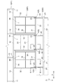
図1、図2に示すように、架設部支持構造は、第1躯体1側から張り出された架設部3の先端側の被支持梁31(被支持部の一例)が、第2躯体2側から張り出された受梁23(受部の一例)上に滑り支承4を介して支持されるもので、地震時等における第1躯体1と第2躯体2の挙動の違いを滑り支承4にて吸収しながら架設部3を支持することができる。
An embodiment of the erection portion installation structure of the present invention will be described with reference to the drawings.
As shown in FIGS. 1 and 2, in the erection portion support structure, the supported beam 31 (an example of the supported portion) on the tip end side of the
図1に示すように、第1躯体1は、複数層を有する第1建物B1の骨組を構成するもので、柱11や梁12、床スラブ(図示省略)、架設部3等から構成される。第2躯体2は、複数層を有して第1建物B1と間隔を空けて構築される第2建物B2の骨組を構成するもので、柱21や梁22、受梁23、床スラブ24(図2〜図4参照)等から構成される。
As shown in FIG. 1, the
架設部3は、第1躯体1の所定階から張り出して第2躯体2の所定階にエクスパンションジョイント(図示省略)を介して接続されるものとして構成される。図示例では、架設部3は、渡り廊下の床の骨組を構成する床構成部位3Aと、その床構成部位3Aの廊下幅方向(図1中のX方向)の両外側に配置されて下階に対する屋根の骨組を構成する屋根構成部位3Bとを有するものを例示している。架設部3は、梁成や高さ位置の異なる複数種の梁31〜34や床材35(図2参照)、屋根材36(図3、図4参照)等から構成される。
The
架設部3には、平面視でY方向(架設部3の張り出し方向)に沿って延びる複数本の主梁32が備えられる。複数本の主梁32は、平面視でY方向に直交するX方向(張り出し方向に交差する交差方向)に間隔を空けて配置される。複数本の主梁32は、基端部が第1躯体1のX方向に沿う梁(大梁)12の外側面に溶接やボルト等で接合される。主梁32の梁成(高さ寸法)H32は、架設部3の複数種の梁31〜34のうちで最も大きく設定される。
The
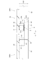
架設部3の床構成部位3A及び屋根構成部位3Bの先端側には、平面視でX方向に沿って延びて複数本の主梁32の先端部に接合手段で溶接やボルト等で接合される被支持梁31が備えられる。図2〜図4に示すように、被支持梁31は、その梁成H31が主梁32の梁成H32よりも小さく設定され、架設部3の床構成部位3A及び屋根構成部位3Bの高位側(上方側)に配置される。
The tip side of the
図1に戻り、架設部3の床構成部位3Aには、平面視でX方向やY方向に沿って延びて主梁32や被支持梁31や第1躯体1のX方向に沿う梁(大梁)12に溶接やボルト等で接合される複数本の床支持梁33が備えられる。図示は省略するが、複数本の床支持梁33は、その梁成が主梁32の梁成H32よりも小さく設定され、架設部3の床構成部位3Aの高位側(上方側)に配置される。そして、当該床支持梁33の上部にコンクリート製等の床材35(図4参照)が支持される。
Returning to FIG. 1, the
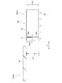
架設部3の屋根構成部位3Bには、平面視でX方向やY方向に沿って延びて主梁32や被支持梁31や第1躯体1のX方向に沿う梁(大梁)12に接続される複数本の屋根支持梁34が備えられる。図4に示すように、複数本の屋根支持梁34は、その梁成H34が主梁32の梁成H32よりも小さく設定され、架設部3の屋根構成部位3Bの低位側(下方側)に配置される。そして、当該屋根支持梁34の下部に折版屋根等の屋根材36が支持される。
The
図1、図2に示すように、第2躯体2側から張り出された複数本の受梁23は、基端部が第2躯体2のX方向に沿う梁22の外側面等に接合されて第1躯体1側に延びる片持ち梁として構成され、平面視でX方向に設定配置間隔を空けて配置される。受梁23の設定配置間隔は、第2躯体2の柱21の配置間隔よりも小で、架設部3の主梁32の配置間隔と同等に設定される。また、受梁23は、第2躯体2のY方向に沿う梁22に連続するように配置される。
As shown in FIGS. 1 and 2, the plurality of receiving
そして、図1、図2に示すように、受梁23の長さ方向の中間部の上面に滑り支承4が設置され、その滑り支承4の上に架設部3の被支持梁31が載置される。滑り支承4は、受梁23の上面に取り付けられる滑り材と、被支持梁31の下面側のベースプレート31aの下面に取り付けられた滑り板等を備えて構成され、受梁23と被支持梁31の水平方向の滑動を許容するようになっている。
Then, as shown in FIGS. 1 and 2, a sliding
被支持梁31と受梁23とそれらの間に介在する滑り支承4とで構成される滑り支承部Sは、架設部3の主梁32を含まずに構成され、夫々の主梁32の近傍位置に配置される。各滑り支承部Sは、各主梁32に対して架設部3の横幅方向(X方向)の中央側(内側)で隣接する位置に配置される。
The sliding bearing portion S composed of the supported
被支持梁31と受梁23とそれらの間に介在する滑り支承4とで構成される滑り支承部Sにおいて、架設部3の主梁32が配置される高さ領域(主梁32の梁成H32が存在する高さ領域)に被支持梁31と滑り支承4と受梁23が配置されるように、被支持梁31及び受梁23の夫々の梁成H31,H23(高さ寸法)と高さ位置とが設定される。本実施形態では、滑り支承部Sの略全体(全体又は略全体の一例)が、主梁32が配置される高さ領域に配置されるように、被支持梁31及び受梁23の夫々の梁成H31,H23(高さ寸法)と高さ位置とが設定される。
In the sliding support portion S composed of the supported
具体的には、被支持梁31は、それの梁成H31が主梁32の梁成H32の略半分(略半分以下の一例)に設定されて主梁32の略上半分の高さ領域に配置される。また、受梁23は、それの梁成H23が滑り支承4の厚み寸法(高さ寸法)を考慮して主梁32の半分よりも若干小さな寸法(略半分以下の一例)に設定されて主梁32の略下半分の高さ領域に配置される。
Specifically, in the supported
このように被支持梁31及び受梁23の夫々の梁成H31,H23と高さ位置とが設定されることで、滑り支承部Sは、架設部3の主梁32の高さ領域から屋根材36の取り付けに略影響しない僅かな範囲で下方にはみ出すものの、略全体が架設部3の主梁32が配置される高さ領域に配置される。
そのため、架設部3の底面において滑り支承部Sが主梁32よりも下方に出っ張ることを略無くすことができ、主梁32や屋根支持梁34の下部に支持される屋根材36を滑り支承部Sに邪魔されることなく簡単且つ意匠性良く設置することができる。
By setting the beam formations H31 and H23 of the supported
Therefore, it is possible to substantially eliminate the sliding support portion S protruding below the
なお、架設部3の主梁32の高さ領域から滑り支承部Sが全く下方にはみ出さないように、主梁32の高さ領域の一部領域に滑り支承部Sの全体が配置されるようにしてもよい。ちなみに、図示例では、滑り支承部Sは、第2躯体2の梁22の全体と同じ高さ寸法で同じ高さ位置に配置される。
The entire sliding bearing portion S is arranged in a part of the height region of the
受梁23の先端部には、被支持梁31の脱落を防止するためのストッパー23aが備えられる。当該ストッパー23Aは、受梁23の先端部の上面に接合された鉄骨部材から構成される。また、受梁23の基端部と第2躯体2の梁22との接合部、被支持梁31の滑り支承4の直上部位、受梁23のストッパー23Aの直下部位には、鉛直姿勢や水平姿勢のリブやプレート等の鉄骨製の補強部材R1が備えられる。
The tip of the receiving
ちなみに、図3に示すように、被支持梁31は、架設部3の横幅方向(X方向)の外側の主梁32の先端部に対しては、その側面における略上半分にガゼットプレート32aによるボルト接合や溶接接合等により接合される。被支持梁31と主梁32との接合部には、鉄骨製のリブやプレート等の適宜の補強部材R2が備えられる。
Incidentally, as shown in FIG. 3, the supported
また、図4に示すように、被支持梁31は架設部3の高位側(上方側)に配置され、屋根支持梁34は架設部3の屋根構成部位3Bの低位側(下方側)に配置されるので、被支持梁31の下部には、鉛直姿勢や水平姿勢のプレート等の鉄骨部材で構成されて下向きに突出する接続ブラケット31Aが備えられ、その接続ブラケット31Aに屋根支持梁34が接合される。この接続ブラケット31Aには、ガゼットプレート31bが備えられ、屋根支持梁34は、当該ガゼットプレート31bによるボルト接合により被支持梁31に接合される。
Further, as shown in FIG. 4, the supported
〔別実施形態〕
本発明の他の実施形態について説明する。尚、以下に説明する各実施形態の構成は、それぞれ単独で適用することに限らず、他の実施形態の構成と組み合わせて適用することも可能である。
[Another Embodiment]
Other embodiments of the present invention will be described. It should be noted that the configurations of the respective embodiments described below are not limited to being applied independently, but can also be applied in combination with the configurations of other embodiments.
(1)前述の実施形態では、滑り支承部Sにおいて、架設部3の主梁32が配置される高さ領域に被支持梁31と滑り支承4と受梁23が配置されるように、被支持梁31及び受梁23の夫々の梁成H31,H23と高さ位置とが設定される場合を例に示したが、架設部3の主梁32が配置される高さ領域に少なくとも滑り支承4が配置されるように、被支持梁31及び受梁23の夫々の梁成H31,H23(高さ寸法)と高さ位置とが設定されてもよく、更には、架設部3の主梁32が配置される高さ領域に少なくとも滑り支承4及び受梁23が配置されるように、被支持梁31及び受梁23の夫々の梁成H31,H23(高さ寸法)と高さ位置とが設定されてもよい。
(1) In the above-described embodiment, in the sliding support portion S, the supported
(2)前述の実施形態では、滑り支承部Sが、主梁32の近傍位置に配置される場合を例に示したが、場合によっては隣り合う主梁32の中間位置等に配置されてもよい。
(2) In the above-described embodiment, the case where the sliding bearing portion S is arranged in the vicinity of the
(3)滑り支承部Sを構成する被支持部や受部は、前述の実施形態で示した被支持梁31や受梁23に限らず、各種の構成を採用することができる。
(3) The supported portion and the receiving portion constituting the sliding bearing portion S are not limited to the supported
1 第1躯体
2 第2躯体
3 架設部
4 滑り支承
23 受梁(受部)
31 被支持梁(被支持部)
32 主梁
H23 受梁の梁成
H31 被支持梁の梁成
H32 主梁の梁成
S 滑り支承部
1
31 Supported beam (supported part)
32 Main beam H23 Beam formation of receiving beam H31 Beam formation of supported beam H32 Beam formation of main beam S Sliding bearing
Claims (5)
前記被支持部と前記受部とそれらの間に介在する前記滑り支承とで構成される滑り支承部において、前記架設部において張り出し方向に延びる主梁が配置される高さ領域に少なくとも前記滑り支承が配置されるように、前記被支持部及び前記受部の夫々の高さ寸法と高さ位置とが設定される架設部支持構造。 The supported portion on the tip end side of the erection portion overhanging from the first skeleton side is a erection portion support structure supported via a sliding bearing on the receiving portion overhanging from the second skeleton side.
In a sliding bearing portion composed of the supported portion, the receiving portion, and the sliding bearing interposed between them, at least the sliding bearing is provided in a height region where a main beam extending in an overhanging direction is arranged in the erection portion. An erection portion support structure in which the height dimensions and height positions of the supported portion and the receiving portion are set so as to be arranged.
前記受部が、前記第2躯体側から張り出された受梁にて構成され、当該受梁が、前記主梁の略半分以下の梁成に設定されて前記主梁の略下半分が配置される高さ領域に配置される請求項3記載の架設部支持構造。 The supported portion is composed of a supported beam extending in a crossing direction intersecting the main beam in a plan view on the tip end side of the erection portion and connected to the main beam, and the supported beam is the main beam. It is set in the beam formation of about half or less of the beam and is arranged in the height area where the upper half of the main beam is arranged.
The receiving portion is composed of a receiving beam overhanging from the second skeleton side, the receiving beam is set to a beam formation of about half or less of the main beam, and the substantially lower half of the main beam is arranged. The erection portion support structure according to claim 3, which is arranged in a height region to be formed.
Priority Applications (1)
| Application Number | Priority Date | Filing Date | Title |
|---|---|---|---|
| JP2020075407A JP2021172995A (en) | 2020-04-21 | 2020-04-21 | Support structure for erection part |
Applications Claiming Priority (1)
| Application Number | Priority Date | Filing Date | Title |
|---|---|---|---|
| JP2020075407A JP2021172995A (en) | 2020-04-21 | 2020-04-21 | Support structure for erection part |
Publications (1)
| Publication Number | Publication Date |
|---|---|
| JP2021172995A true JP2021172995A (en) | 2021-11-01 |
Family
ID=78279267
Family Applications (1)
| Application Number | Title | Priority Date | Filing Date |
|---|---|---|---|
| JP2020075407A Pending JP2021172995A (en) | 2020-04-21 | 2020-04-21 | Support structure for erection part |
Country Status (1)
| Country | Link |
|---|---|
| JP (1) | JP2021172995A (en) |
-
2020
- 2020-04-21 JP JP2020075407A patent/JP2021172995A/en active Pending
Similar Documents
| Publication | Publication Date | Title |
|---|---|---|
| KR101878607B1 (en) | Modular unit having opening hole beam and modular unit structure using the same | |
| JP6990979B2 (en) | Framing structure of a building | |
| KR102200236B1 (en) | Wall module and wall structure | |
| JP2021172995A (en) | Support structure for erection part | |
| JP6274792B2 (en) | Building ramen frame | |
| JP6962753B2 (en) | Building unit and unit type building | |
| JP7032051B2 (en) | Floor structure construction method and floor structure reuse method | |
| JP7434067B2 (en) | steel building | |
| JP6286164B2 (en) | Frame structure | |
| JP7415475B2 (en) | overhang floor structure | |
| KR102627366B1 (en) | Non-welding channel system | |
| JPH11131663A (en) | Frame body | |
| JP5320498B1 (en) | Attached units and unit buildings | |
| WO2023182318A1 (en) | Joint structure and method for constructing joint structure | |
| JP5301700B1 (en) | Attached units and unit buildings | |
| JP2023168863A (en) | Building floor structure and building | |
| JP4804869B2 (en) | Building unit | |
| KR101687408B1 (en) | Prefabricated Steel floor structure for buildings | |
| JP7045214B2 (en) | Frame structure | |
| JP2021183765A (en) | roof | |
| JPH0853812A (en) | Horizontal joint construction of main girder in temporary bridge, and horizontal joint material | |
| JPH11140972A (en) | Building | |
| JP3574625B2 (en) | Unit building and its construction method | |
| JP4205884B2 (en) | Unit building | |
| JP2024057262A (en) | Object Support Structure |