JP2020534636A - アークブラストユニットが設けられた電気スイッチ - Google Patents
アークブラストユニットが設けられた電気スイッチ Download PDFInfo
- Publication number
- JP2020534636A JP2020534636A JP2020504723A JP2020504723A JP2020534636A JP 2020534636 A JP2020534636 A JP 2020534636A JP 2020504723 A JP2020504723 A JP 2020504723A JP 2020504723 A JP2020504723 A JP 2020504723A JP 2020534636 A JP2020534636 A JP 2020534636A
- Authority
- JP
- Japan
- Prior art keywords
- movable
- piston
- contact
- electric switch
- enclosure
- Prior art date
- Legal status (The legal status is an assumption and is not a legal conclusion. Google has not performed a legal analysis and makes no representation as to the accuracy of the status listed.)
- Granted
Links
Images

Classifications
-
- H—ELECTRICITY
- H01—ELECTRIC ELEMENTS
- H01H—ELECTRIC SWITCHES; RELAYS; SELECTORS; EMERGENCY PROTECTIVE DEVICES
- H01H33/00—High-tension or heavy-current switches with arc-extinguishing or arc-preventing means
- H01H33/70—Switches with separate means for directing, obtaining, or increasing flow of arc-extinguishing fluid
- H01H33/88—Switches with separate means for directing, obtaining, or increasing flow of arc-extinguishing fluid the flow of arc-extinguishing fluid being produced or increased by movement of pistons or other pressure-producing parts
- H01H33/90—Switches with separate means for directing, obtaining, or increasing flow of arc-extinguishing fluid the flow of arc-extinguishing fluid being produced or increased by movement of pistons or other pressure-producing parts this movement being effected by or in conjunction with the contact-operating mechanism
- H01H33/91—Switches with separate means for directing, obtaining, or increasing flow of arc-extinguishing fluid the flow of arc-extinguishing fluid being produced or increased by movement of pistons or other pressure-producing parts this movement being effected by or in conjunction with the contact-operating mechanism the arc-extinguishing fluid being air or gas
-
- H—ELECTRICITY
- H01—ELECTRIC ELEMENTS
- H01H—ELECTRIC SWITCHES; RELAYS; SELECTORS; EMERGENCY PROTECTIVE DEVICES
- H01H1/00—Contacts
- H01H1/12—Contacts characterised by the manner in which co-operating contacts engage
- H01H1/36—Contacts characterised by the manner in which co-operating contacts engage by sliding
- H01H1/38—Plug-and-socket contacts
- H01H1/385—Contact arrangements for high voltage gas blast circuit breakers
-
- H—ELECTRICITY
- H01—ELECTRIC ELEMENTS
- H01H—ELECTRIC SWITCHES; RELAYS; SELECTORS; EMERGENCY PROTECTIVE DEVICES
- H01H33/00—High-tension or heavy-current switches with arc-extinguishing or arc-preventing means
- H01H33/70—Switches with separate means for directing, obtaining, or increasing flow of arc-extinguishing fluid
- H01H33/72—Switches with separate means for directing, obtaining, or increasing flow of arc-extinguishing fluid having stationary parts for directing the flow of arc-extinguishing fluid, e.g. arc-extinguishing chamber
- H01H33/74—Switches with separate means for directing, obtaining, or increasing flow of arc-extinguishing fluid having stationary parts for directing the flow of arc-extinguishing fluid, e.g. arc-extinguishing chamber wherein the break is in gas
-
- H—ELECTRICITY
- H01—ELECTRIC ELEMENTS
- H01H—ELECTRIC SWITCHES; RELAYS; SELECTORS; EMERGENCY PROTECTIVE DEVICES
- H01H33/00—High-tension or heavy-current switches with arc-extinguishing or arc-preventing means
- H01H33/70—Switches with separate means for directing, obtaining, or increasing flow of arc-extinguishing fluid
- H01H33/88—Switches with separate means for directing, obtaining, or increasing flow of arc-extinguishing fluid the flow of arc-extinguishing fluid being produced or increased by movement of pistons or other pressure-producing parts
- H01H33/90—Switches with separate means for directing, obtaining, or increasing flow of arc-extinguishing fluid the flow of arc-extinguishing fluid being produced or increased by movement of pistons or other pressure-producing parts this movement being effected by or in conjunction with the contact-operating mechanism
- H01H33/905—Switches with separate means for directing, obtaining, or increasing flow of arc-extinguishing fluid the flow of arc-extinguishing fluid being produced or increased by movement of pistons or other pressure-producing parts this movement being effected by or in conjunction with the contact-operating mechanism the compression volume being formed by a movable cylinder and a semi-mobile piston
-
- H—ELECTRICITY
- H01—ELECTRIC ELEMENTS
- H01H—ELECTRIC SWITCHES; RELAYS; SELECTORS; EMERGENCY PROTECTIVE DEVICES
- H01H33/00—High-tension or heavy-current switches with arc-extinguishing or arc-preventing means
- H01H33/70—Switches with separate means for directing, obtaining, or increasing flow of arc-extinguishing fluid
- H01H33/88—Switches with separate means for directing, obtaining, or increasing flow of arc-extinguishing fluid the flow of arc-extinguishing fluid being produced or increased by movement of pistons or other pressure-producing parts
- H01H33/90—Switches with separate means for directing, obtaining, or increasing flow of arc-extinguishing fluid the flow of arc-extinguishing fluid being produced or increased by movement of pistons or other pressure-producing parts this movement being effected by or in conjunction with the contact-operating mechanism
- H01H2033/906—Switches with separate means for directing, obtaining, or increasing flow of arc-extinguishing fluid the flow of arc-extinguishing fluid being produced or increased by movement of pistons or other pressure-producing parts this movement being effected by or in conjunction with the contact-operating mechanism with pressure limitation in the compression volume, e.g. by valves or bleeder openings
-
- H—ELECTRICITY
- H01—ELECTRIC ELEMENTS
- H01H—ELECTRIC SWITCHES; RELAYS; SELECTORS; EMERGENCY PROTECTIVE DEVICES
- H01H33/00—High-tension or heavy-current switches with arc-extinguishing or arc-preventing means
- H01H33/70—Switches with separate means for directing, obtaining, or increasing flow of arc-extinguishing fluid
- H01H33/88—Switches with separate means for directing, obtaining, or increasing flow of arc-extinguishing fluid the flow of arc-extinguishing fluid being produced or increased by movement of pistons or other pressure-producing parts
- H01H33/90—Switches with separate means for directing, obtaining, or increasing flow of arc-extinguishing fluid the flow of arc-extinguishing fluid being produced or increased by movement of pistons or other pressure-producing parts this movement being effected by or in conjunction with the contact-operating mechanism
- H01H2033/908—Switches with separate means for directing, obtaining, or increasing flow of arc-extinguishing fluid the flow of arc-extinguishing fluid being produced or increased by movement of pistons or other pressure-producing parts this movement being effected by or in conjunction with the contact-operating mechanism using valves for regulating communication between, e.g. arc space, hot volume, compression volume, surrounding volume
-
- H—ELECTRICITY
- H01—ELECTRIC ELEMENTS
- H01H—ELECTRIC SWITCHES; RELAYS; SELECTORS; EMERGENCY PROTECTIVE DEVICES
- H01H33/00—High-tension or heavy-current switches with arc-extinguishing or arc-preventing means
- H01H33/02—Details
- H01H33/022—Details particular to three-phase circuit breakers
Landscapes
- Circuit Breakers (AREA)
- Arc-Extinguishing Devices That Are Switches (AREA)
Abstract
Description
2 可動接点
6 前部空洞
9 ブローパイプ
10 ノズル
11 湾曲、エルボードリル
12 分離場所
13 ピストン
14 開口部
15 可動接点チューリップ
16 管状接点ユニット
17 キャリッジ
18 軸
19 長手方向スロット
20 中央ボア
25 圧縮シリンダ、エンクロージャ
26 開口部
27 圧縮チャンバ
28 バルブ
29 圧縮ばね、ばねセット
32 スロット
X−X 移動方向
Claims (8)
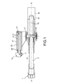
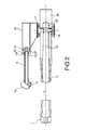
- 少なくとも1つの固定接点(1)と、前記固定接点(1)の前で、前記固定接点(1)と接合される閉位置と前記固定接点(1)から分離される開位置との間を移動方向(X−X)にスライドする少なくとも1つの可動接点(2)とを備える電気スイッチであって、前記移動方向(X−X)に平行な少なくとも1つの固定ブローパイプ(9)であって、前記ブローパイプ(9)は、前端のノズル(10)であって、前記可動接点(2)が前記固定接点(1)から分離する場所(12)に向けられるノズル(10)、および後端のピストン(13)を備えるブローパイプ(9)と、前記可動接点(2)に接続され、前記ブローパイプ(9)の周りおよび前記ピストン(13)の周りをスライドする可動エンクロージャ(25)と、前記ノズル(10)と連通し、前記エンクロージャ(25)、前記ピストン(13)および前記ブローパイプ(9)によって画定される圧縮チャンバ(27)とを備えることを特徴とする、電気スイッチ。
- 前記圧縮チャンバ(27)は、前記圧縮チャンバ(27)内の1バール未満の負圧で開くバルブ(28)が設けられることを特徴とする、請求項1に記載の電気スイッチ。
- 前記バルブ(28)は、前記ピストン(13)に設けられることを特徴とする、請求項2に記載の電気スイッチ。
- 前記ピストン(13)は、細長い形状を有し、前記エンクロージャ(25)は、対応する細長い断面を有することを特徴とする、請求項1乃至3のいずれか1項に記載の電気スイッチ。
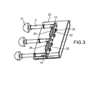
- 複数の前記固定接点(1)および前記可動接点(2)であって、前記可動接点(2)は、共に可動式である複数の前記固定接点(1)および前記可動接点(2)と、複数の前記ブローパイプ(9)であって、ブローパイプ(9)の各々は、前記固定接点(1)および前記可動接点(2)のそれぞれに関連付けられるが、前記ピストン(13)は、単一であり、すべての前記ブローパイプ(9)に共通であり、前記エンクロージャ(25)もまた、単一である複数の前記ブローパイプ(9)とを備えることを特徴とする、請求項1乃至4のいずれか1項に記載の電気スイッチ。
- 前記ブローパイプ(9)は、前記ピストンに沿って一列に配置され、前記固定接点(1)および前記可動接点(2)は、ブローパイプ(9)の前記列に平行な列に配置されることを特徴とする、請求項4および5に記載の電気スイッチ。
- 前記エンクロージャ(25)は、キャリッジ(17)に固着され、前記可動接点(2)も変位させることを特徴とする、請求項1乃至6のいずれか1項に記載の電気スイッチ。
- 前記エンクロージャ(25)と前記ブローパイプ(9)の両方は、前記移動方向(X−X)に沿って前記可動接点(2)と重なるように配置されることを特徴とする、請求項1乃至7のいずれか1項に記載の電気スイッチ。
Applications Claiming Priority (1)
| Application Number | Priority Date | Filing Date | Title |
|---|---|---|---|
| PCT/EP2017/069350 WO2019024978A1 (en) | 2017-07-31 | 2017-07-31 | ELECTRIC SWITCH COMPRISING A ARC BLOWING UNIT |
Publications (2)
| Publication Number | Publication Date |
|---|---|
| JP2020534636A true JP2020534636A (ja) | 2020-11-26 |
| JP6980090B2 JP6980090B2 (ja) | 2021-12-15 |
Family
ID=59677189
Family Applications (1)
| Application Number | Title | Priority Date | Filing Date |
|---|---|---|---|
| JP2020504723A Active JP6980090B2 (ja) | 2017-07-31 | 2017-07-31 | アークブラストユニットが設けられた電気スイッチ |
Country Status (5)
| Country | Link |
|---|---|
| US (1) | US10984973B2 (ja) |
| JP (1) | JP6980090B2 (ja) |
| KR (1) | KR102466070B1 (ja) |
| CN (1) | CN110914947B (ja) |
| WO (1) | WO2019024978A1 (ja) |
Families Citing this family (3)
| Publication number | Priority date | Publication date | Assignee | Title |
|---|---|---|---|---|
| EP3709335B1 (en) * | 2019-03-12 | 2022-06-22 | ABB Schweiz AG | Earthing module |
| DE102019212109A1 (de) | 2019-08-13 | 2021-02-18 | Siemens Aktiengesellschaft | Elektrische Schalteinrichtung |
| CN119170431B (zh) * | 2024-09-30 | 2025-06-03 | 浙江正泰电气科技有限公司 | 快速接地开关及gis设备 |
Citations (3)
| Publication number | Priority date | Publication date | Assignee | Title |
|---|---|---|---|---|
| JPS49103171A (ja) * | 1973-02-05 | 1974-09-30 | ||
| US4046979A (en) * | 1974-11-25 | 1977-09-06 | Siemens Aktiengesellschaft | Arc quenching arrangement for a gas-flow type circuit breaker |
| JPS62234825A (ja) * | 1986-03-26 | 1987-10-15 | アルストム | 圧縮誘電ガスブレ−カ− |
Family Cites Families (16)
| Publication number | Priority date | Publication date | Assignee | Title |
|---|---|---|---|---|
| GB434501A (en) | 1934-03-08 | 1935-09-06 | Gerald John Sutton | Improvements in or relating to means for delivering material in quantities of predetermined weight |
| DE2108871B2 (de) | 1971-02-25 | 1980-05-29 | Calor-Emag Elektrizitaets-Aktiengesellschaft, 4030 Ratingen | Druckgasschalter mit einem geschlossenen Gaskreis |
| DE2316009B2 (de) * | 1973-03-30 | 1977-11-10 | Zusatz in: 24 55 674 Siemews A.G, tOOQ Betlm \md 8000 München | Gasstroemungsschalter |
| FR2327626A1 (fr) * | 1975-10-09 | 1977-05-06 | Alsthom Cgee | Appareil de coupure electrique a soufflage d'arc |
| FR2619246B1 (fr) * | 1987-08-03 | 1989-11-17 | Alsthom | Disjoncteur a haute ou moyenne tension a gaz sous pression a energie de coupure prelevee sur celle de l'arc |
| US4780581A (en) * | 1987-10-30 | 1988-10-25 | Rte Corporation | Suicide switch/interrupter with variable volume chamber and puffer action |
| FR2641409B1 (fr) * | 1989-01-02 | 1996-04-26 | Alsthom Gec | Disjoncteur a haute et moyenne tension a gaz de soufflage |
| FR2651065B1 (fr) * | 1989-08-18 | 1996-07-05 | Alsthom Gec | Disjoncteur a moyenne tension a autosoufflage |
| JPH04284319A (ja) | 1991-03-13 | 1992-10-08 | Hitachi Ltd | ガス遮断器 |
| JP2910582B2 (ja) * | 1994-10-31 | 1999-06-23 | 日新電機株式会社 | 電力用ガス遮断器 |
| DE29509015U1 (de) | 1995-05-24 | 1995-08-03 | Siemens AG, 80333 München | Hochspannungs-Leistungsschalter mit einem feststehenden Heizvolumen |
| DE29620027U1 (de) * | 1996-11-06 | 1997-01-16 | Siemens AG, 80333 München | Hochspannungsdruckgasschalter mit einer Löscheinrichtung |
| DE29716152U1 (de) * | 1997-08-28 | 1997-10-30 | Siemens AG, 80333 München | Hochspannungsschalter mit einem Kompressionszylinder |
| DE19928080C5 (de) * | 1999-06-11 | 2006-11-16 | Siemens Ag | Hochspannungsleistungsschalter mit einem Abströmkanal |
| EP1939910A1 (de) * | 2006-12-27 | 2008-07-02 | ABB Technology AG | Druckgasschalter mit einer radialen Durchströmöffnung |
| US8063333B2 (en) | 2008-02-05 | 2011-11-22 | Southern States, Inc. | Limited flash-over electric power switch |
-
2017
- 2017-07-31 JP JP2020504723A patent/JP6980090B2/ja active Active
- 2017-07-31 KR KR1020207005519A patent/KR102466070B1/ko active Active
- 2017-07-31 US US16/635,386 patent/US10984973B2/en active Active
- 2017-07-31 CN CN201780093577.3A patent/CN110914947B/zh active Active
- 2017-07-31 WO PCT/EP2017/069350 patent/WO2019024978A1/en not_active Ceased
Patent Citations (3)
| Publication number | Priority date | Publication date | Assignee | Title |
|---|---|---|---|---|
| JPS49103171A (ja) * | 1973-02-05 | 1974-09-30 | ||
| US4046979A (en) * | 1974-11-25 | 1977-09-06 | Siemens Aktiengesellschaft | Arc quenching arrangement for a gas-flow type circuit breaker |
| JPS62234825A (ja) * | 1986-03-26 | 1987-10-15 | アルストム | 圧縮誘電ガスブレ−カ− |
Also Published As
| Publication number | Publication date |
|---|---|
| CN110914947B (zh) | 2021-12-28 |
| KR20200029585A (ko) | 2020-03-18 |
| US20200161066A1 (en) | 2020-05-21 |
| CN110914947A (zh) | 2020-03-24 |
| WO2019024978A1 (en) | 2019-02-07 |
| JP6980090B2 (ja) | 2021-12-15 |
| KR102466070B1 (ko) | 2022-11-10 |
| US10984973B2 (en) | 2021-04-20 |
Similar Documents
| Publication | Publication Date | Title |
|---|---|---|
| US8030590B2 (en) | Gas-circuit breaker | |
| US6437273B2 (en) | Hybrid circuit breaker | |
| US9299507B2 (en) | Gas circuit breaker | |
| JP6980090B2 (ja) | アークブラストユニットが設けられた電気スイッチ | |
| US2933575A (en) | Circuit interrupters | |
| US4086461A (en) | High-voltage circuit-interrupters | |
| CN104143472B (zh) | 压气式灭弧装置及使用该灭弧装置的高压断路器 | |
| CN107564751B (zh) | 负荷开关设备 | |
| US2668217A (en) | Liquid switch | |
| JP5218449B2 (ja) | ガス遮断器 | |
| CN104124086B (zh) | 一种电气灭弧装置 | |
| CN112908771B (zh) | 一种断路器及其灭弧室 | |
| US5587571A (en) | Combined-action puffer circuit-breaker | |
| US2913559A (en) | Fluid-blast circuit interrupter | |
| CN207165455U (zh) | 负荷开关设备 | |
| GB516532A (en) | Improvements in or relating to electric circuit-breaking devices of the gas-blast type | |
| EP3273463B1 (en) | Electric switch provided with an arc-blasting unit | |
| JP6639692B2 (ja) | ガス遮断器 | |
| US2228232A (en) | Expulsion circuit breaker | |
| US20130265693A1 (en) | Circuit breaker | |
| US1959183A (en) | Electrical switching apparatus | |
| CN202474794U (zh) | 一种用于40.5kV 带有直动压气式负荷开关的电缆分支箱 | |
| JP6834277B2 (ja) | ガス絶縁開閉装置 | |
| US2811614A (en) | Circuit breaker employing sickle shaped contact, engaging stationary contact and impulse grid | |
| CN108766828A (zh) | 一种用于高压sf6断路器带有圆柱凸起的喷口 |
Legal Events
| Date | Code | Title | Description |
|---|---|---|---|
| A521 | Request for written amendment filed |
Free format text: JAPANESE INTERMEDIATE CODE: A523 Effective date: 20200512 |
|
| A621 | Written request for application examination |
Free format text: JAPANESE INTERMEDIATE CODE: A621 Effective date: 20200717 |
|
| A977 | Report on retrieval |
Free format text: JAPANESE INTERMEDIATE CODE: A971007 Effective date: 20210611 |
|
| A131 | Notification of reasons for refusal |
Free format text: JAPANESE INTERMEDIATE CODE: A131 Effective date: 20210618 |
|
| A521 | Request for written amendment filed |
Free format text: JAPANESE INTERMEDIATE CODE: A523 Effective date: 20210916 |
|
| TRDD | Decision of grant or rejection written | ||
| A01 | Written decision to grant a patent or to grant a registration (utility model) |
Free format text: JAPANESE INTERMEDIATE CODE: A01 Effective date: 20211019 |
|
| A61 | First payment of annual fees (during grant procedure) |
Free format text: JAPANESE INTERMEDIATE CODE: A61 Effective date: 20211116 |
|
| R150 | Certificate of patent or registration of utility model |
Ref document number: 6980090 Country of ref document: JP Free format text: JAPANESE INTERMEDIATE CODE: R150 |
|
| R250 | Receipt of annual fees |
Free format text: JAPANESE INTERMEDIATE CODE: R250 |