JP2020508944A - Automatic storage and retrieval system - Google Patents
Automatic storage and retrieval system Download PDFInfo
- Publication number
- JP2020508944A JP2020508944A JP2019546017A JP2019546017A JP2020508944A JP 2020508944 A JP2020508944 A JP 2020508944A JP 2019546017 A JP2019546017 A JP 2019546017A JP 2019546017 A JP2019546017 A JP 2019546017A JP 2020508944 A JP2020508944 A JP 2020508944A
- Authority
- JP
- Japan
- Prior art keywords
- storage container
- storage
- connector
- vehicle
- container
- Prior art date
- Legal status (The legal status is an assumption and is not a legal conclusion. Google has not performed a legal analysis and makes no representation as to the accuracy of the status listed.)
- Pending
Links
Images


Classifications
-
- B—PERFORMING OPERATIONS; TRANSPORTING
- B65—CONVEYING; PACKING; STORING; HANDLING THIN OR FILAMENTARY MATERIAL
- B65G—TRANSPORT OR STORAGE DEVICES, e.g. CONVEYORS FOR LOADING OR TIPPING, SHOP CONVEYOR SYSTEMS OR PNEUMATIC TUBE CONVEYORS
- B65G1/00—Storing articles, individually or in orderly arrangement, in warehouses or magazines
- B65G1/02—Storage devices
- B65G1/04—Storage devices mechanical
- B65G1/0492—Storage devices mechanical with cars adapted to travel in storage aisles
-
- B—PERFORMING OPERATIONS; TRANSPORTING
- B65—CONVEYING; PACKING; STORING; HANDLING THIN OR FILAMENTARY MATERIAL
- B65G—TRANSPORT OR STORAGE DEVICES, e.g. CONVEYORS FOR LOADING OR TIPPING, SHOP CONVEYOR SYSTEMS OR PNEUMATIC TUBE CONVEYORS
- B65G1/00—Storing articles, individually or in orderly arrangement, in warehouses or magazines
- B65G1/02—Storage devices
- B65G1/04—Storage devices mechanical
- B65G1/0407—Storage devices mechanical using stacker cranes
- B65G1/0435—Storage devices mechanical using stacker cranes with pulling or pushing means on either stacking crane or stacking area
-
- B—PERFORMING OPERATIONS; TRANSPORTING
- B65—CONVEYING; PACKING; STORING; HANDLING THIN OR FILAMENTARY MATERIAL
- B65G—TRANSPORT OR STORAGE DEVICES, e.g. CONVEYORS FOR LOADING OR TIPPING, SHOP CONVEYOR SYSTEMS OR PNEUMATIC TUBE CONVEYORS
- B65G1/00—Storing articles, individually or in orderly arrangement, in warehouses or magazines
- B65G1/02—Storage devices
- B65G1/04—Storage devices mechanical
- B65G1/137—Storage devices mechanical with arrangements or automatic control means for selecting which articles are to be removed
- B65G1/1373—Storage devices mechanical with arrangements or automatic control means for selecting which articles are to be removed for fulfilling orders in warehouses
-
- B—PERFORMING OPERATIONS; TRANSPORTING
- B65—CONVEYING; PACKING; STORING; HANDLING THIN OR FILAMENTARY MATERIAL
- B65G—TRANSPORT OR STORAGE DEVICES, e.g. CONVEYORS FOR LOADING OR TIPPING, SHOP CONVEYOR SYSTEMS OR PNEUMATIC TUBE CONVEYORS
- B65G1/00—Storing articles, individually or in orderly arrangement, in warehouses or magazines
- B65G1/02—Storage devices
- B65G1/04—Storage devices mechanical
- B65G1/10—Storage devices mechanical with relatively movable racks to facilitate insertion or removal of articles
-
- B—PERFORMING OPERATIONS; TRANSPORTING
- B65—CONVEYING; PACKING; STORING; HANDLING THIN OR FILAMENTARY MATERIAL
- B65G—TRANSPORT OR STORAGE DEVICES, e.g. CONVEYORS FOR LOADING OR TIPPING, SHOP CONVEYOR SYSTEMS OR PNEUMATIC TUBE CONVEYORS
- B65G2201/00—Indexing codes relating to handling devices, e.g. conveyors, characterised by the type of product or load being conveyed or handled
- B65G2201/02—Articles
- B65G2201/0235—Containers
-
- B—PERFORMING OPERATIONS; TRANSPORTING
- B65—CONVEYING; PACKING; STORING; HANDLING THIN OR FILAMENTARY MATERIAL
- B65G—TRANSPORT OR STORAGE DEVICES, e.g. CONVEYORS FOR LOADING OR TIPPING, SHOP CONVEYOR SYSTEMS OR PNEUMATIC TUBE CONVEYORS
- B65G2814/00—Indexing codes relating to loading or unloading articles or bulk materials
- B65G2814/03—Loading or unloading means
- B65G2814/0347—Loading or unloading means for cars or linked car-trains with individual load-carriers
- B65G2814/0352—Feeding or discharging devices operated by cars
Abstract
複数の目的地領域との間でアイテムを格納又は取得する方法及び装置が提供される。アイテムは、独立制御される複数の運搬車両の1つに積み込まれる。運搬車両は、経路に沿って配置された目的地領域との間の経路をたどる。目的地領域は、複数の格納コンテナを水平方向に互いに前後に収容するための奥行きを有するように構成される。複数の格納コンテナは、解放可能に相互接続されてもよく、相互接続された格納コンテナの1つを取得することで、接続された1つ以上の格納コンテナを移動させる。A method and apparatus for storing or retrieving items to and from a plurality of destination areas is provided. Items are loaded into one of a plurality of independently controlled transport vehicles. The transport vehicle follows a route to and from a destination area located along the route. The destination area is configured to have a depth for accommodating a plurality of storage containers in front of and behind each other in the horizontal direction. The plurality of storage containers may be releasably interconnected, and acquiring one of the interconnected storage containers moves one or more connected storage containers.
Description
本出願は、2017年2月24日に出願された米国仮特許出願第62/463,352号及び2018年2月26に出願された米国特許出願第15/905,810号の優先権を主張する。
これにより、前述の各出願の開示全体を本明細書で引用により援用する。
This application claims priority to US Provisional Patent Application No. 62 / 463,352 filed February 24, 2017 and US Patent Application No. 15 / 905,810 filed February 26, 2018. I do.
The entire disclosure of each of the aforementioned applications is hereby incorporated by reference herein.
本発明は、1つ又は複数の物体を第1の位置から第2の位置に搬送する材料取り扱いシステムに関し、より具体的には、複数の格納コンテナが複数の格納場所に格納される自動格納及び取得システムに関し、これらの格納場所では、いくつかの格納コンテナは、他の格納コンテナの後ろに位置する。 The present invention relates to a material handling system for transporting one or more objects from a first location to a second location, and more particularly to automatic storage and storage where multiple storage containers are stored in multiple storage locations. With respect to the acquisition system, at these storage locations, some storage containers are located behind other storage containers.
多くの大規模組織は、例えば、顧客注文を履行するために、無数かつ多様なアイテムを格納し取得する広大な格納領域を有している。
数百又は数千の格納領域に対してアイテムを手動で仕分け及び取得するには、膨大な労力を要する。
多くの分野では、人件費を削減し、顧客注文の履行に必要な時間を減らして顧客サービスを向上させるために、自動採取が開発されている。
多くの場合、格納密度、アクセスしやすさ、フットプリント、コスト等のような、システムをセットアップする際の変数の間には、トレードオフが存在する。
たとえば、自動格納及び取得(ASR)システムの格納密度を向上させることで、このような自動格納及び取得システムのコスト及びスペース要件(フットプリント)の両方を削減可能である。
ただし、自動格納及び取得システムの格納密度が高すぎる場合、個々のアイテムを格納及び取得可能な容易さと速度とが低下し、自動格納及び取得システムが多くの用途に適さない場合がある。
Many large organizations have vast storage areas for storing and retrieving countless and diverse items, for example, to fulfill customer orders.
Manually sorting and acquiring items for hundreds or thousands of storage areas requires enormous effort.
In many areas, automatic picking is being developed to reduce labor costs, reduce the time required to fulfill customer orders, and improve customer service.
In many cases, there is a trade-off between variables in setting up the system, such as storage density, accessibility, footprint, cost, and the like.
For example, increasing the storage density of an automatic storage and retrieval (ASR) system can reduce both the cost and space requirements (footprint) of such automatic storage and retrieval systems.
However, if the storage density of the automatic storage and retrieval system is too high, the ease and speed with which individual items can be stored and retrieved decreases, and the automatic storage and retrieval system may not be suitable for many applications.
例として、自動格納及び取得システムは、複数の独立動作車両を含む。
このような自動格納及び取得システムは、両側に格納場所を備えた通路として構成され、車両が通路内の経路に沿って移動する。
自動格納及び取得システムの容量は、通路を高く又は長くすることで増やすことができる。
また、通路を追加してもよい。
しかし、多くの状況では、そのような自動格納及び取得システムをスペース上利用できない場合や、容量の増加という利点をコストが上回る場合がある。
したがって、一部の用途では、システムのスループットに大きな影響を与えることなく、低コスト、かつ、小さなフットプリントで格納密度を向上させるASRシステムが必要となっている。
As an example, an automatic storage and retrieval system includes a plurality of independently operating vehicles.
Such an automatic storage and acquisition system is configured as a passage with storage places on both sides, and the vehicle moves along a path in the passage.
The capacity of the automatic storage and acquisition system can be increased by increasing or decreasing the length of the aisle.
Further, a passage may be added.
However, in many situations, such automatic storage and retrieval systems may not be available in space, or the cost may outweigh the benefits of increased capacity.
Therefore, in some applications, there is a need for an ASR system that increases storage density with a low cost and small footprint without significantly affecting system throughput.
上記に照らして、自動格納及び取得システムは、アイテムを格納及び取得する方法及び装置を提供する。
本自動格納及び取得システムは、複数の格納場所又は目的地領域と、目的地領域へのアイテムの配送又は目的地領域からのアイテムの取得のための複数の運搬車両と、を含む。
運搬車両は、目的地領域への経路をたどる。
In light of the above, an automatic storage and retrieval system provides a method and apparatus for storing and retrieving items.
The automatic storage and acquisition system includes a plurality of storage locations or destination areas and a plurality of transport vehicles for delivering items to or obtaining items from the destination areas.
The transport vehicle follows a route to the destination area.
また、本発明は、改良された材料取り扱い自動格納及び取得システムも提供してもよい。
この自動格納及び取得システムでは、独立動作可能な車両が、格納コンテナを格納場所に配送し、かつ、格納場所から取得するよう動作可能であり、格納場所は、複数の格納コンテナを水平方向に前後配置で収容するのに充分な奥行きを有する。
この自動格納及び取得システムは、車両を軌道に沿って格納場所に案内する軌道を含んでもよい。
加えて、複数の格納場所が互いに垂直方向に隔てられるように、格納場所が配置されてもよい。
例えば、格納場所は、複数の行又は列状の格納場所の配列として構成されてもよい。
また、格納コンテナは、隣接する格納コンテナと解放可能に接続可能であってもよく、そうすることで、第1格納場所内の第1格納コンテナを移動させると、第1格納場所内で第2格納コンテナが移動する。
The present invention may also provide an improved material handling automatic storage and acquisition system.
In this automatic storage and acquisition system, an independently operable vehicle is operable to deliver a storage container to a storage location and obtain the storage container from the storage location, and the storage location is configured to move a plurality of storage containers back and forth horizontally. It has enough depth to accommodate the arrangement.
The automatic storage and acquisition system may include a track that guides the vehicle along a track to a storage location.
In addition, the storage locations may be arranged such that the plurality of storage locations are vertically separated from one another.
For example, the storage locations may be configured as an array of a plurality of rows or columns of storage locations.
Also, the storage container may be releasably connectable to an adjacent storage container, so that when the first storage container in the first storage location is moved, the second storage location in the first storage location is changed. The storage container moves.
また、本発明は、アイテムを目的地に配送及び取得するための複数の独立動作可能な車両を含む、複数のアイテムを格納又は取得する材料取り扱いシステムも提供する。
オプションで、本自動格納及び取得システムは、車両を案内する軌道を含む。
本システムは、複数の格納場所を含み、複数の格納場所は、互いに垂直方向に離れて配置されている。
格納場所は、軌道に沿って配置されてもよい。
本自動格納及び取得システムは、複数の格納コンテナも含む。
1つ以上の格納場所が、複数の格納コンテナを収容するよう構成されている。
格納コンテナは、格納場所内で互いに隣接して格納される複数の格納コンテナを接続する、相互接続のためのコネクタを含む。
コネクタが複数の格納コンテナを接続することで、格納場所にある格納コンテナの1つを移動させると、同じ格納場所にある相互接続された格納コンテナが露わになる。
車両は、車両と格納場所との間で格納コンテナを輸送するように構成された輸送機構を含んでもよい。
輸送機構は、第1コンテナ又は第2格納コンテナが車両に対して移動する際、相互接続された第1コンテナ及び第2格納コンテナを移動するよう動作可能であってもよい。
The present invention also provides a material handling system for storing or retrieving a plurality of items, including a plurality of independently operable vehicles for delivering and retrieving items to a destination.
Optionally, the automatic storage and acquisition system includes a track to guide the vehicle.
The system includes a plurality of storage locations, wherein the plurality of storage locations are vertically spaced apart from each other.
The storage locations may be arranged along a track.
The automatic storage and acquisition system also includes a plurality of storage containers.
One or more storage locations are configured to accommodate a plurality of storage containers.
The storage container includes a connector for interconnecting a plurality of storage containers stored adjacent to each other in the storage location.
When the connector connects a plurality of storage containers and moves one of the storage containers at the storage location, the interconnected storage containers at the same storage location are exposed.
The vehicle may include a transport mechanism configured to transport a storage container between the vehicle and a storage location.
The transport mechanism may be operable to move the interconnected first and second storage containers as the first or second storage container moves relative to the vehicle.
別の態様によれば、材料取り扱いシステムは、互いに離れて配置された複数の全般的に水平な軌道区画を有する軌道システムを含んでもよい。
また、本軌道システムは、互いに離れて配置された複数の全般的に垂直な軌道区画を含んでもよい。
垂直及び水平な軌道区画を相互接続して、環状軌道を形成してもよい。
According to another aspect, a material handling system may include a track system having a plurality of generally horizontal track sections spaced apart from each other.
The track system may also include a plurality of generally vertical track sections spaced apart from each other.
Vertical and horizontal track sections may be interconnected to form an annular track.
さらに、別の態様によれば、本発明は、第1コネクタ及び第2コネクタを有する、材料取り扱いシステムのための格納コンテナを提供する。
これらのコネクタによって、第2格納コンテナに対する第1格納コンテナの水平方向の移動を阻止する接続を提供可能である。
第1コネクタと第2コネクタとの接続が、水平移動の間の前記第2格納コンテナの重量を支持するのに充分であってもよく、それにより、第1コネクタと第2コネクタとが接続されている際に、第1格納コンテナを水平に移動させると、第2格納コンテナが水平に移動する。
さらに、第1コネクタと第2コネクタとの接続は、第2格納コンテナに対する第1格納コンテナの垂直方向の移動を許容してもよい。
According to yet another aspect, the present invention provides a storage container for a material handling system having a first connector and a second connector.
These connectors can provide a connection that prevents the first storage container from moving horizontally relative to the second storage container.
The connection between the first connector and the second connector may be sufficient to support the weight of the second storage container during horizontal movement, whereby the first connector and the second connector are connected. In this case, when the first storage container is moved horizontally, the second storage container is moved horizontally.
Further, the connection between the first connector and the second connector may allow vertical movement of the first storage container relative to the second storage container.
別の態様によれば、自動格納及び取得システムは、第1格納コンテナ及び第2格納コンテナを解放可能に接続するための第1コネクタ及び第2コネクタを有する格納コンテナを提供してもよく、第1コネクタが第2コネクタに対して垂直に移動することで、第1コネクタが第2コネクタから切り離されるように、第1コネクタと第2コネクタとが構成される。 According to another aspect, an automatic storage and retrieval system may provide a storage container having a first connector and a second connector for releasably connecting a first storage container and a second storage container, The first connector and the second connector are configured such that the first connector is separated from the second connector by moving the one connector vertically with respect to the second connector.
さらに、本発明は、格納コンテナを互いに相互接続するための第1コネクタ及び第2コネクタを有する格納コンテナを提供し、第1コネクタが舌部を備え、第2コネクタが舌部を収容するように構成される溝部を備える。 Further, the invention provides a storage container having a first connector and a second connector for interconnecting the storage containers with each other, wherein the first connector comprises a tongue and the second connector receives the tongue. It has a groove configured.
別の態様によれば、本発明は、第1格納コンテナと第2格納コンテナとが配置される格納場所を提供し、この格納場所は、第1格納コンテナと第2格納コンテナとを水平方向に倣って収容するよう構成され、第1格納コンテナが、第2格納コンテナの前に配置される。
オプションで、運搬車両が第1格納コンテナに倣う際、第1格納コンテナが第2格納コンテナを運搬車両から隔てるように、この格納場所が構成されてもよい。
According to another aspect, the present invention provides a storage location where a first storage container and a second storage container are located, wherein the storage location horizontally connects the first storage container and the second storage container. The first storage container is configured to accommodate the copy, and the first storage container is disposed in front of the second storage container.
Optionally, the storage location may be configured such that when the transport vehicle follows the first storage container, the first storage container separates the second storage container from the transport vehicle.
さらに、本発明は、各々の格納場所が複数の格納コンテナを格納するように構成されている、複数の格納場所を有する材料取り扱いシステムを提供する。
オプションで、格納場所は、それぞれ奥行きを有し、格納コンテナのうちの第1格納コンテナ及び第2格納コンテナは、それぞれ長さを有し、格納場所の奥行きは、第1格納コンテナと第2格納コンテナとの合計長さと少なくとも同じ長さを有する。
Further, the present invention provides a material handling system having a plurality of storage locations, wherein each storage location is configured to store a plurality of storage containers.
Optionally, the storage locations each have a depth, the first storage container and the second storage container of the storage containers each have a length, and the depth of the storage location is the first storage container and the second storage container. It has at least the same length as the total length with the container.
別の態様によれば、本発明は、材料取り扱いシステム用の運搬車両を提供し、各車両は、格納コンテナを収容するほぼ平面のプラットフォームを有する。 According to another aspect, the invention provides a transport vehicle for a material handling system, wherein each vehicle has a substantially planar platform for housing a storage container.
さらに、別の態様によれば、本発明は、格納場所の第2格納ラックから離れて位置している格納場所の第1格納ラックを備え、第1格納ラックと第2格納ラックとの間に通路が形成される、材料取り扱いシステムを提供する。 Further, according to another aspect, the present invention comprises a first storage rack at a storage location remote from the second storage rack at the storage location, wherein the first storage rack is located between the first storage rack and the second storage rack. A material handling system is provided wherein a passage is formed.
オプションで、本材料取り扱いシステムは、通路の端部に配置された採取所を含んでもよい。
車両は、格納コンテナを採取所に配送し、動作者が採取所で格納コンテナからアイテムを取得可能である。
Optionally, the material handling system may include a collection station located at the end of the passage.
The vehicle delivers the storage container to the collection site, where the operator can obtain items from the storage container at the collection site.
別の態様によれば、本システムは、通路内で移動可能な車両を含んでもよい。
車両は、軌道に係合する駆動車輪を備えてもよく、格納場所の格納ラックは、格納コンテナが軌道を越えて通路内に水平に突出するように、軌道に対して位置してもよい。
According to another aspect, the system may include a vehicle movable within the aisle.
The vehicle may include drive wheels that engage the track, and the storage rack at the storage location may be positioned relative to the track such that the storage container projects horizontally across the track and into the aisle.
さらなる態様によれば、本発明は、材料取り扱いシステム用の格納コンテナを提供し、格納コンテナが、格納コンテナを配送する車両の輸送機構と係合するように構成されている1つ以上の係合要素を含む。 According to a further aspect, the present invention provides a storage container for a material handling system, wherein the storage container comprises one or more engagements configured to engage a transport mechanism of a vehicle delivering the storage container. Contains elements.
さらなる態様によれば、本発明は、複数のアイテムを格納又は取得する材料取り扱いシステムで使用するための格納コンテナを提供する。
格納コンテナは、複数の壁と第1コネクタと第2コネクタとを含む。
第1コネクタと第2コネクタとは、2つの格納コンテナの間で解放可能な接続を形成して接続ができるように構成されている。
格納コンテナは、材料取扱いシステムの輸送機構と協働して格納コンテナを水平に移動させるよう構成されている、係合要素を含んでもよい。
さらに、材料取り扱いシステムは、格納場所を含んでもよく、格納コンテナの長さは、格納場所の奥行きの半分以下であってもよい。
これにより、2つの格納コンテナが共に接続されている際、2つの格納コンテナが格納場所内に収まる。
また、第1コネクタと第2コネクタとは、解放可能な接続を形成するよう接続可能であってもよい。
According to a further aspect, the present invention provides a storage container for use in a material handling system for storing or retrieving a plurality of items.
The storage container includes a plurality of walls, a first connector, and a second connector.
The first connector and the second connector are configured to form a releasable connection between the two storage containers for connection.
The storage container may include an engagement element configured to cooperate with the transport mechanism of the material handling system to move the storage container horizontally.
Further, the material handling system may include a storage location, and the length of the storage container may be less than half the depth of the storage location.
Thus, when the two storage containers are connected together, the two storage containers fit within the storage location.
Also, the first connector and the second connector may be connectable to form a releasable connection.
さらに、本発明は、材料取り扱いシステムで使用するための第1格納コンテナと第2格納コンテナとの組み合わせを提供してもよい。
2つの格納コンテナは、同様に構成されてもよく、第1格納コンテナの第1コネクタが第2格納コンテナの第2コネクタと接続可能であることで2つの格納コンテナを接続し、運搬車両の輸送機構によって第1格納コンテナを水平方向に移動させることで、第2格納コンテナを移動させる。
オプションで、第1格納コンテナの第1コネクタと第2格納コンテナの第2コネクタとの接続によって、第2格納コンテナに対する第1格納コンテナの水平方向の移動が阻止される。
Further, the present invention may provide a combination of a first storage container and a second storage container for use in a material handling system.
The two storage containers may be similarly configured, wherein the first connector of the first storage container is connectable with the second connector of the second storage container to connect the two storage containers and transport the transport vehicle. The second storage container is moved by moving the first storage container in the horizontal direction by the mechanism.
Optionally, the connection between the first connector of the first storage container and the second connector of the second storage container prevents horizontal movement of the first storage container relative to the second storage container.
また、本発明は、複数の格納場所から格納コンテナを格納及び取得する方法を提供する。
本方法は、複数の格納場所の間の移送経路に沿って、第1格納コンテナを有する第1車両を駆動するステップを含む。
第1格納コンテナは、第1車両から第1格納場所に積み下ろされる。
第1格納コンテナは、第1格納場所内で第2格納コンテナと解放可能に接続される。
そして、積み下ろすステップの後、第1車両を第1格納場所から移動させる。
The present invention also provides a method for storing and obtaining a storage container from a plurality of storage locations.
The method includes driving a first vehicle having a first storage container along a transfer path between the plurality of storage locations.
The first storage container is unloaded from the first vehicle to the first storage location.
The first storage container is releasably connected to the second storage container in the first storage location.
Then, after the unloading step, the first vehicle is moved from the first storage location.
別の態様によれば、格納コンテナを格納及び取得する方法は、格納場所内の第1格納コンテナを格納場所内の第2格納コンテナから切り離すステップを含む。
オプションで、解放可能に接続するステップが、第1格納コンテナを第2格納コンテナに対して垂直方向に移動させるステップを含む。
According to another aspect, a method of storing and retrieving a storage container includes disconnecting a first storage container in the storage location from a second storage container in the storage location.
Optionally, releasably connecting comprises moving the first storage container vertically relative to the second storage container.
さらなる態様によれば、車両を使用して格納コンテナを格納及び取得する方法は、第1格納コンテナを第2格納コンテナに対して垂直方向に移動させることにより、接続された第1格納コンテナと第2格納コンテナとを切り離すステップを含む。 According to a further aspect, a method for storing and retrieving a storage container using a vehicle includes moving the first storage container vertically with respect to the second storage container so that the first storage container is connected to the first storage container. Disconnecting from the two storage containers.
さらに別の態様によれば、車両を使用して格納コンテナを格納及び取得する方法は、第1格納コンテナと第2格納コンテナとを解放可能に接続するステップの後に、第1格納コンテナを車両上に積み込むステップを含み、これにより、積み込むステップの間、第1格納コンテナが、第2格納コンテナを車両に向かって引っ張る。 According to yet another aspect, a method for storing and retrieving a storage container using a vehicle includes, after the step of releasably connecting the first storage container and the second storage container, placing the first storage container on the vehicle. , Whereby the first storage container pulls the second storage container toward the vehicle during the loading step.
さらなる態様によれば、車両を使用して格納コンテナを格納及び取得する方法は、第1格納コンテナを格納場所に積み下ろすステップを含む。
積み下ろすステップは、第1格納コンテナを第2格納コンテナに向かって押すことで第2格納コンテナを格納場所のより奥に動かす、第1格納コンテナを第2格納コンテナに向かって押すステップを含む。
積み下ろすステップは、第1車両上の積み下ろし機構を動作することで第1格納コンテナを第1車両の外へと動かす、第1車両上の積み下ろし機構を動作するステップを含んでもよい。
According to a further aspect, a method of storing and obtaining a storage container using a vehicle includes unloading a first storage container to a storage location.
Loading and unloading includes pushing the first storage container toward the second storage container by pushing the first storage container toward the second storage container to move the second storage container further into the storage location.
The step of unloading may include the step of operating the unloading mechanism on the first vehicle by operating the unloading mechanism on the first vehicle to move the first storage container out of the first vehicle.
前述の概要及び本発明の実施形態の以下の詳細な説明は、添付の図面と併せて読むことで最良に理解される。 The foregoing summary, as well as the following detailed description of embodiments of the invention, is best understood when read in conjunction with the appended drawings.
図1は、格納及び取得装置の斜視図。 FIG. 1 is a perspective view of a storage and acquisition device.
図2は、図1に示す格納及び取得装置の軌道の部分側面図。 FIG. 2 is a partial side view of the track of the storage and acquisition device shown in FIG.
図3は、図1に示す格納及び取得装置の車両の拡大斜視図。 FIG. 3 is an enlarged perspective view of a vehicle of the storage and acquisition device shown in FIG.
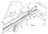
図4は、図2に示す軌道のゲートの拡大斜視図。 FIG. 4 is an enlarged perspective view of a track gate shown in FIG. 2.
図5は、図2に示す軌道のゲートの拡大斜視図。 FIG. 5 is an enlarged perspective view of the track gate shown in FIG. 2.
図6は、図2に示す軌道のゲートの拡大斜視図。 FIG. 6 is an enlarged perspective view of the track gate shown in FIG. 2.
図7は、図3に示す車両の車輪及び図2に示す軌道の一部の部分拡大図。 7 is a partially enlarged view of a wheel of the vehicle shown in FIG. 3 and a part of a track shown in FIG. 2;
図8は、図1に示す装置の複数の格納場所の概略側面図。 FIG. 8 is a schematic side view of a plurality of storage locations of the device shown in FIG.
図9は、図1に示す装置の格納場所内の格納コンテナの概略側面図。 9 is a schematic side view of a storage container in a storage location of the device shown in FIG.
図10Aは、図9の格納コンテナをある場所から別の場所に移動するプロセスのステップを示す概略図。 FIG. 10A is a schematic diagram illustrating the steps of the process of moving the storage container of FIG. 9 from one location to another.
図10Bは、図9の格納コンテナをある場所から別の場所に移動するプロセスのステップを示す概略図。 FIG. 10B is a schematic diagram illustrating the steps of the process of moving the storage container of FIG. 9 from one location to another.
図10Cは、図9の格納コンテナをある場所から別の場所に移動するプロセスのステップを示す概略図。 FIG. 10C is a schematic diagram illustrating steps in a process of moving the storage container of FIG. 9 from one location to another.
図10Dは、図9の格納コンテナをある場所から別の場所に移動するプロセスのステップを示す概略図。 FIG. 10D is a schematic diagram illustrating steps in a process of moving the storage container of FIG. 9 from one location to another.
図10Eは、図9の格納コンテナをある場所から別の場所に移動するプロセスのステップを示す概略図。 FIG. 10E is a schematic diagram showing the steps of the process of moving the storage container of FIG. 9 from one location to another.
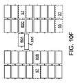
図10Fは、図9の格納コンテナをある場所から別の場所に移動するプロセスのステップを示す概略図。 FIG. 10F is a schematic diagram illustrating the steps of the process of moving the storage container of FIG. 9 from one location to another.
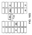
図10Gは、図9の格納コンテナをある場所から別の場所に移動するプロセスのステップを示す概略図。 FIG. 10G is a schematic diagram illustrating the steps of the process of moving the storage container of FIG. 9 from one location to another.
図10Hは、図9の格納コンテナをある場所から別の場所に移動するプロセスのステップを示す概略図。 FIG. 10H is a schematic diagram showing the steps of the process of moving the storage container of FIG. 9 from one location to another.
図11は、図1に示す材料取り扱い装置の格納ラックの部分斜視図。 FIG. 11 is a partial perspective view of a storage rack of the material handling device shown in FIG.
図12は、図1に示す材料取り扱い装置の格納ラックの車両を含む部分斜視図。 FIG. 12 is a partial perspective view including a vehicle of a storage rack of the material handling apparatus shown in FIG. 1.
図13は、図1に示す材料取り扱い装置の解放可能な複数の格納コンテナが接続されている部分側面図。 FIG. 13 is a partial side view of the material handling apparatus shown in FIG. 1 to which a plurality of releasable storage containers are connected.
図14は、図1に示す材料取り扱い装置の解放可能な複数の格納コンテナが切り離されている部分側面図。 FIG. 14 is a partial side view of the material handling apparatus shown in FIG. 1 with a plurality of releasable storage containers separated.
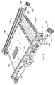
ここで、図1を参照すると、アイテムを格納及び/又は取得するように適用された材料取り扱い装置が、全体として10で示されている。
材料取り扱い装置10は、第1の場所と第2の場所との間の移送経路に沿ってアイテムを移送する複数の車両200を含む。
第1の場所は、1つ以上の格納ラック内の複数の格納場所50の中から選択可能な格納場所であり、第2の場所は、アイテムを採取、仕分け及び/又は格納コンテナ80のような格納用の容器に輸送する、採取所である物品輸送所300である。
材料取り扱い装置10は、アイテム(又は、アイテムを収容する格納コンテナ)を運搬経路に沿って移動させる。
Referring now to FIG. 1, a material handling apparatus adapted to store and / or retrieve items is indicated generally at 10.
The first location is a storage location that can be selected from a plurality of
The
材料取り扱い装置10は、複数の移送車両又は車両200を含み、これらの車両200は、1つ以上の格納ラック35、格納ラック40に隣接する通路20内の、1つ以上の経路に沿って移動する。
格納ラック35、格納ラック40は、複数の格納コンテナ80を格納するよう構成されている。
例えば、図1に示すように、通路20は、車両200が1つ以上の経路に沿って通路20内を移動するように、一対の格納ラック35、格納ラック40の間に形成された細長い通路であってもよい。
軌道110は、車両200が格納ラック内の格納場所に移動するための1つ以上の経路を、通路20内に提供してもよい。
例えば、実施形態は、通路20の片側の前方の格納ラック35に隣接する前方軌道115を含んでもよい。
後方の格納ラック40に隣接する後方軌道120を前方軌道115から間隔を空けて配置することで、通路20を形成してもよい。
車両200は、軌道110に沿って通路20内を移動してもよい。
例えば、車両200は、前方軌道115と係合する1つ以上の前方車輪と、後方軌道120と係合する1つ以上の後方車輪と、によって支持されてもよい。
The
The
For example, as shown in FIG. 1, the
The
For example, embodiments may include a
The
The
For example,
各格納ラック35、格納ラック40は、様々なアイテムを格納する格納コンテナ80を格納するための複数の格納場所50を提供する。
車両200は、軌道110に沿って格納場所50に移動する。
格納場所50では、車両200は、車両200から格納場所50の1つにアイテムを輸送可能である。
同様に、車両200は、格納場所50の1つから車両200上にアイテムを輸送可能である。
さらに、車両200がこの車両200から格納場所50にアイテムを輸送すると同時に、異なる格納場所50から車両200上にアイテムを輸送するように構成されてもよい。
格納場所50は、通路20に隣接する場所の配列として配置されてもよい。
加えて、以下でさらに説明するように、格納ラック35、格納ラック40は、これらの格納ラック内の格納コンテナ80の格納密度を向上させるために、格納コンテナ80を2つ以上の奥行きで格納可能なように格納奥行きを提供してもよい。
<格納ラック>
Each
The
At
Similarly, the
Further, the
The
In addition, as described further below, storage racks 35 and 40 can store
<Storage rack>
格納ラック35、格納ラック40及びこれらの格納ラック35、40内の格納場所50について、ここで、さらに詳細に説明する。
図1を参照すると、システムは、1つ又は複数の格納ラック35、格納ラック40を含んでもよい。
格納ラック35と格納ラック40とは、アイテムを受け取るための目的地領域又は格納場所50の配列を提供してもよい。
格納場所50は、列状に配置されてもよいが、格納場所50は、(行状のように)様々な構成の任意の形態で配置されてもよい。
システムは、アイテムの格納領域50への配送及び/又は格納領域50からの取得を行う。
アイテムは、個々のアイテムが格納場所50に格納されるように構成されてもよい。
ただし、一般的な動作環境では、アイテムは、格納コンテナやプラットフォームなどの格納機構に格納される。
The storage racks 35, storage racks 40 and the
Referring to FIG. 1, the system may include one or
The
The system delivers items to the
Items may be configured such that individual items are stored in
However, in a general operating environment, items are stored in a storage mechanism such as a storage container or a platform.
ここで、図8から図12を参照して、格納ラック35、格納ラック40と、特に、格納場所50とについて、より詳細に説明する。
格納場所50は、様々な構成のうちの任意のものであってもよい。
たとえば、最も単純な構成は、アイテム又はアイテムを保持する格納コンテナ80を支持するための棚である。
同様に、格納場所50は、格納機構と協働することで、格納場所50で格納機構を支持する、1つ以上のブラケットを含んでもよい。
Here, with reference to FIGS. 8 to 12, the
For example, the simplest configuration is a shelf for supporting an item or
Similarly,
図8及び図11から図12に示すように、格納ラック35は、水平梁のような複数の水平支持体と相互接続されている、垂直支持梁のような複数の垂直支持体130を含んでもよい。
本例では、軌道110は、垂直支持梁及び水平支持梁の一部を形成してもよい。
例えば、格納ラック35は、コラムの配列を備えていてもよい。
ここで、各コラムは、複数の支持体によって形成されている。
各コラムは、2つの前方の垂直支持梁と2つの後方の垂直支持梁によって定義されてもよい。
図11に示されるように、前方の垂直支持梁からなる垂直支持体130は、軌道110の垂直区画を備えてもよい。
各コラムは、複数の格納場所50を含んでもよい。
具体的には、各コラムは、複数の格納領域又はセル50に分けられる。
各セル50は、格納コンテナ80をセルに格納できるように格納コンテナ80を支持する支持要素を含む。
支持要素は、格納場所50で格納コンテナ80を支持するための様々な要素のうちの任意のものであってもよい。
たとえば、各格納場所50には、格納コンテナ80を置くことができる、棚又は他の水平支持体が含まれてもよい。
例えば、図8及び図11、図12に示すように、格納ラック35は、垂直支持体130に取り付けられたLチャネル52などの複数のブラケットを含んでもよい。
このLチャネル52からなるブラケットは、各格納場所50の奥まで実質的に延在してもよい。
このようにして、各格納場所50は、隣接する複数の垂直支持体130の間で延在し、一対の水平支持要素52に隣接する位置から、一対の上方の水平支持体に隣接する位置又は格納ラックの上部に隣接する位置まで、上方に延在する領域として定義されてもよい。
As shown in FIGS. 8 and 11-12, the
In this example, the
For example, the
Here, each column is formed by a plurality of supports.
Each column may be defined by two front vertical support beams and two rear vertical support beams.
As shown in FIG. 11, a
Each column may include a plurality of
Specifically, each column is divided into a plurality of storage areas or
Each
The support element may be any of a variety of elements for supporting
For example, each
For example, as shown in FIGS. 8, 11 and 12, the
The bracket made up of the
In this manner, each
さらに、図11に示すように、各格納場所50は、格納コンテナ80が通路に向かって内側に突出し、格納コンテナ80の内側端部が垂直支持体を越えて内側に突出するように構成されてもよい。
言い換えると、格納コンテナ80は、(通路20に対して)格納コンテナ80の内側端部が通路20内に超えて出るように、格納場所50に格納されてもよい。
Further, as shown in FIG. 11, each
In other words, the
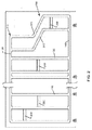
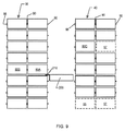
ここで、図9を参照すると、格納ラックは、1つ以上の格納場所50が複数の格納コンテナ80を収容するのに充分な奥行きとなるように構成されてもよい。
例えば、1つ以上の格納場所50が、格納コンテナ80の少なくとも約2倍の奥行きを有し、2つの格納コンテナ80を格納することができ、一方の格納コンテナ80は、他方の格納コンテナ80の後ろに格納される。
格納場所50は、任意の数の格納コンテナ80を収容するように構成されてもよい。
例えば、格納ラック35、格納ラック40は、1つ以上の格納場所50が3つの格納コンテナ80を収容できるように構成されてもよく、その結果、格納コンテナ80は、3層の奥行きで配置される。
そのような実施形態では、格納場所50は、格納コンテナ80の長さの約3倍の奥行きがある。
同様に、格納ラックの奥行きを、格納コンテナ80の長さの約「n」倍と増大させると、奥行き「n」に格納される「n」個の格納コンテナ80を収容することができる。
ここで、「n」は、整数である。
Referring now to FIG. 9, the storage rack may be configured such that one or
For example, one or
For example,
In such an embodiment, the
Similarly, when the depth of the storage rack is increased to about “n” times the length of the
Here, “n” is an integer.
図9の配置では、「n」の奥行き配置で格納コンテナ80を格納する配置に関連して示されている。
ここでは、「n」=2である。
材料取り扱い装置10は、片側に1つの格納ラックのみを含んでいてもよいが、図9では、2つの格納ラック、つまり、前方の格納ラック35と後方の格納ラック40とを有する。
さらに、前方の格納ラック35と後方の格納ラック40は、格納コンテナ80を2層の奥行き配置で収容するように構成されている。
ただし、格納ラック35、格納ラック40を、同じ数の格納コンテナ80を収容するように構成する必要はない。
例えば、前方の格納ラック35は、奥行き2基の格納ラックとして構成されてもよく、後方の格納ラック40は、奥行き1基の格納ラックとして構成されてもよい。
The arrangement of FIG. 9 is shown in relation to an arrangement in which the
Here, “n” = 2.
The
Further, the
However, it is not necessary to configure the
For example, the
以下の説明では、図8から図9に示す配置に関連して格納場所を説明する。
各格納場所50は、内側の格納場所55及び外側の格納場所57を含む。
内側の格納場所55及び外側の格納場所57のそれぞれは、格納コンテナ80を収容するように構成される。
内側の格納場所55は、通路20に隣接している。
外側の格納場所57は、内側の格納場所55の後方にあり、したがって、内側の格納場所55は、外側の格納場所57を通路20及び車両200から隔てている。
本例では、内側の格納場所55は、格納コンテナ80の長さとほぼ同じ奥行きを有している。
同様に、外側の格納場所57は、格納コンテナ80の長さとほぼ同じ奥行きを有している。
外側の格納場所57は、内側の格納場所55によって通路20から隔てられているため、遠隔の格納場所とみなす。
奥行きが2基を超えるシステムでは、遠隔場所には、内側の格納場所55と1つ以上の外側の格納場所57によって通路20から隔てられた格納場所が含まれる。
In the following description, storage locations will be described in relation to the arrangements shown in FIGS.
Each
Each of the
The
The
In this example, the
Similarly, the
Since the
In systems with more than two depths, remote locations include storage locations separated from the
前述のように、システムは、格納場所50に運搬され、格納場所50との間でアイテムを輸送する複数の車両200を含んでもよい。
特に、車両200は、アイテムを格納場所50に輸送するか、又は、格納場所50からアイテムを引き出すための積み込み/積み下ろし機構210を含んでもよい。
格納コンテナ80が2つ基以上の奥行きに格納される実施形態では、車両200が遠隔の格納場所57の1つに格納された格納コンテナ80を取得することができるように構成される。
たとえば、各車両200は、遠隔の格納場所57に外向きに伸びて遠隔の格納場所57の格納コンテナ80に係合し、格納コンテナ80を内側の格納場所55に移動する、かつ/又は、格納コンテナ80を遠隔の格納場所57から車両200に積み込む、積み込み要素を含んでもよい。
あるいは、別の機構を利用して、格納コンテナ80を遠隔の格納場所57から内側の格納場所55に移動してもよい。
例えば、格納ラックが、遠隔の格納場所57から通路20に向かって格納コンテナ80を駆動するように動作可能な駆動機構を含んでもよい。
駆動機構は、別個に動力を供給されてもよいし、車両200の1つの駆動機構と相互作用してもよい。
さらに別の代替案は、格納コンテナ80の一方を移動すると両方の格納コンテナ80が移動するように、遠隔の格納場所57内の格納コンテナ80をこれと隣接する格納コンテナ80と相互接続することである。
例えば、遠隔の格納場所57内の格納コンテナ80は、内側の格納場所55内の格納コンテナ80と解放可能に接続されてもよい。
内側の格納場所55内の格納コンテナ80が通路20に向かって移動すると、遠隔の格納場所57内の格納コンテナ80は、内側の格納場所55に向かって移動する。
As described above, the system may include a plurality of
In particular, the
In embodiments where the
For example, each
Alternatively, another mechanism may be used to move
For example, the storage rack may include a drive mechanism operable to drive the
The drive mechanism may be separately powered or may interact with one drive mechanism of
Yet another alternative is to interconnect a
For example, a
When the
ここで、図11から図14を参照すると、格納コンテナ80は、隣接する格納コンテナと接続するよう構成されている。
具体的には、格納コンテナ80は、1つ以上の隣接する格納コンテナ80と解放可能に接続するように構成される。
例えば、図13に示すように、解放可能なコネクタ90が、2つの隣接する格納コンテナ80A、格納コンテナ80Bを接続する。
解放可能なコネクタ90は、2つの格納コンテナ80A、80Bを選択的に接続する。
このようにすることで、格納コンテナ80Aを水平方向に移動させると、格納コンテナ80Bも移動する。
加えて、解放可能なコネクタ90は、1つの方向の相対運動を阻止する一方で、第2の方向又は横方向の相対運動を可能にしてもよい。
例えば、接続部は、一方の格納コンテナ80が水平方向に移動することで、他方の格納コンテナ80も移動するように、格納コンテナ80Aと格納コンテナ80Bを接続してもよい。
同時に、一方の格納コンテナを他方の格納コンテナに対して垂直に移動できるように、解放可能なコネクタ90を構成してもよい。
図11及び図13から図14に示す実施形態では、解放可能なコネクタ90は、以下でさらに説明するように、2つの隣接する格納コンテナ80A、80Bを接続又は切り離すための相対的な垂直移動を可能にするように構成される。
Here, referring to FIG. 11 to FIG. 14, the
Specifically,
For example, as shown in FIG. 13, a
A
In this way, when the
In addition,
For example, the connection unit may connect the
At the same time, the
In the embodiment shown in FIGS. 11 and 13-14, the
以下の議論では、格納コンテナ80の詳細が説明される。
格納コンテナ80は、蓋のないカートン又は箱のようなものであってもよく、動作者は、採取所で格納コンテナ80に容易に手を伸ばしてアイテムを取得できる。
本システムは、格納コンテナ80を使用するものとして説明されるが、パレットや類似のプラットフォームなど、さまざまな格納機構の任意のものを使用できることを理解する必要がある。
したがって、以下の説明では、格納コンテナ80という用語は、パレット、プラットフォーム、トレイ、カートン、ボックス、容器又は同様の構造を含むがこれらに限定されない、アイテムを格納及び/又は支持することを目的とするアイテムを含むことが意図される。
In the following discussion, details of the
The
Although the system is described as using a
Accordingly, in the following description, the
格納コンテナ80は、ほぼ平坦な底部83を有する直方体であってもよい。
底部83は、実質的に水平であり、アイテムを取得するためのプラットフォームを形成する。
格納コンテナ80は、底部83から上方に延在する複数のほぼ垂直な壁も含んでいてもよい。
例えば、格納コンテナ80は、ほぼ平行な複数の側壁82を含んでもよい。
格納コンテナは、底部83から上方に突出する前壁84を含んでもよい。
前面は、側壁82を接続するために複数の側壁82の間を延在していてもよい。
さらに、格納コンテナ80は、底部83から上方に突出する後壁86を含んでもよい。
後壁86は、前壁84とほぼ平行であってもよい。
後壁86は、複数の側壁82の間を延在し、側壁82を接続してもよい。
したがって、格納コンテナ80の壁(82、83、84、86)は、アイテムを格納可能な内部空間を定義する。
The
The bottom 83 is substantially horizontal and forms a platform for obtaining items.
The
For example, the
The storage container may include a
The front surface may extend between the plurality of sidewalls 82 to connect the sidewalls 82.
Further, the
The rear wall 86 may be substantially parallel to the
The rear wall 86 may extend between and connect the plurality of side walls 82.
Thus, the walls (82, 83, 84, 86) of the
格納コンテナ80は、車両200と協働して格納コンテナ80を車両200の内外に輸送するように構成される、1つ以上の要素を含んでもよい。
例えば、格納コンテナ80は、車両200と協働するよう構成されるフックや、戻り止めや、ソケットや、他の物理的構造を含んでもよい。
本例では、格納コンテナ80は、車両200の積み込み/積み下ろし要素212と協働するように構成される、保持スロット又は保持溝88を含んでもよい。
保持溝88は、格納コンテナ80の下側で、底部83のよりも下に形成されてもよい。
保持溝88は、図11及び図13に示されるように、格納コンテナ80の前面84の後方に位置していてもよい。
保持溝88は、格納コンテナ80の幅全体に広がるよう延在してもよい。
また、溝88は、図11及び図13に示されるように、保持溝88が貫通溝となるように、両側壁82に開放端部を有してもよい。
図13に示されるように、保持溝88は、車両200の積み込み/積み下ろし要素212の厚さよりも深くてもよく、積み込み/積み下ろし要素212が水平方向に移動する際、積み込み/積み下ろし要素212は、保持溝88B内に入れ子状に留まり、格納コンテナ80を内側又は外側に駆動してもよい。
また、格納コンテナ80は、後壁86の近くに第2の溝又はスロットからなる保持溝88を含んでもよい。
第2の保持溝88は、第1の壁と実質的に同様に構成されてもよく、後壁86の近傍で、後壁86の前方に位置して形成されていてもよい。
For example,
In this example,
The holding groove 88 may be formed below the
The holding groove 88 may be located behind the
The holding groove 88 may extend so as to extend over the entire width of the
Further, as shown in FIGS. 11 and 13, the groove 88 may have open ends on both side walls 82 so that the holding groove 88 becomes a through groove.
As shown in FIG. 13, the retaining groove 88 may be deeper than the thickness of the loading /
The
The second holding groove 88 may be configured substantially similarly to the first wall, and may be formed near the rear wall 86 and in front of the rear wall 86.
図13及び図14を参照すると、隣接する格納コンテナ80A、格納コンテナ80Bを解放可能に接続するための解放可能なコネクタ90が示されている。
コネクタ90を用いることで、遠隔の格納場所57から内側の格納場所55への格納コンテナ80の移動を容易にすることができる。
解放可能なコネクタ90は、協働するフック又はラッチであってもよい。
例えば、解放可能なコネクタ90は、一対の協働可能な前方コネクタ92B、後方コネクタ96Aから形成されてもよい。
前方コネクタ92Bは、格納コンテナ80の前方端部84と接続されていてもよく、後方コネクタ96Aは、格納コンテナ80の後方端部86と接続されていてもよい。
このように、第1格納コンテナ80Bの前方コネクタ92Bは、第2格納コンテナ80Aの後方コネクタ96Aに解放可能に接続可能であることで、2つの格納コンテナ80A、80Bを接続する。
前方コネクタ92Bは、ほぼ垂直に下向きに延びる舌状のフックである(図14の92Bを参照)。
前方コネクタ92Bは、格納コンテナ80の前方端部84に隣接する凹部から下方に突出している。
この例では、前方コネクタ92Bは、L字型ブラケットである。
L字型ブラケットは、格納コンテナ80の底部83にしっかりと固定接続された本体部分を有してもよい。
例えば、前方コネクタ92Bの本体部分は、実質的に水平に延びていてもよく、コネクタ92を通って格納コンテナ80内に延びる留め具によって格納コンテナ80に固定されてもよい。
前方コネクタ92Bの舌部94は、舌部が下方に突出することで第2コネクタ96と係合する垂直フック又はフランジを形成するように、本体部分を横切って突出してもよい。
図13に示すように、前方コネクタ92Bは、保持溝88の前方で、格納コンテナ80に接続されてもよい。
保持溝88は、車両200の積み込み/積み下ろし機構212と係合するために使用される。
Referring to FIGS. 13 and 14, a
By using the
The
For example, the
The front connector 92B may be connected to the
As described above, the front connector 92B of the
The front connector 92B is a tongue-shaped hook that extends substantially vertically downward (see 92B in FIG. 14).
The front connector 92B protrudes downward from a recess adjacent to the
In this example, the front connector 92B is an L-shaped bracket.
The L-shaped bracket may have a body portion that is securely connected to the bottom 83 of the
For example, the body portion of the front connector 92B may extend substantially horizontally and may be secured to the
The tongue 94 of the front connector 92B may protrude across the body portion such that the tongue protrudes downward to form a vertical hook or flange that engages the second connector 96.
As shown in FIG. 13, the front connector 92B may be connected to the
Retaining groove 88 is used to engage loading /
後方コネクタからなる第2コネクタ96は、第1フック92と協働する第2フックであってもよい。
後方コネクタ96は、格納コンテナ80の後方端部86から後方に突出してもよい。
本例では、後方コネクタからなる第2コネクタ96は、垂直上向きに突出するフック又はフランジを組み込んでいる。
具体的には、第2コネクタ96は、第1コネクタ92の舌部94を受け入れるように構成される溝又はチャネル98を含んでもよい。
チャネル98は、このチャネル98が後方端部86から後方に突出するように格納コンテナ80の後方端部86に接続していてもよい。
第2コネクタ96は、格納コンテナ80の底部83にしっかりと固定接続された本体部分を有してもよい。
例えば、後方コネクタ96の本体部分は、実質的に水平に延在するほぼ平坦な部分であり、後方コネクタ96を通って格納コンテナ80内に延在する留め具によって格納コンテナ80に固定されてもよい。
The second connector 96 including the rear connector may be a second hook that cooperates with the
The rear connector 96 may project rearward from a rear end 86 of the
In this example, the second connector 96, which is a rear connector, incorporates a hook or flange that projects vertically upward.
Specifically, second connector 96 may include a groove or
The
The second connector 96 may have a body portion that is securely connected to the bottom 83 of the
For example, the body portion of the rear connector 96 is a substantially flat portion that extends substantially horizontally and may be secured to the
図13に示すように、第1格納コンテナ80Bの前方コネクタ92Bの舌部94Bは、第2格納コンテナ80Aの後方コネクタ96Aのスロット98Aに挿入され、第1格納コンテナ80B及び第2格納コンテナ80Aを接続する。
以下でさらに説明するように、2つの格納コンテナ80A、80B間の接続により、格納コンテナ80の1つが移動した際にこれらの格納コンテナ80A、80Bが一緒に移動できるようになる。
このようにして、第1格納コンテナ80Bを内側の格納場所55から車両200上に引っ張ると、これに接続された格納コンテナ80Aが、遠隔の格納場所57から内側の格納場所55に向かって引っ張られる。
<軌道>
As shown in FIG. 13, the tongue 94B of the front connector 92B of the
As described further below, the connection between the two
Thus, when the
<Orbit>
図1及び図12から理解できるように、軌道110は、格納場所50に隣接して配置されてもよく、車両200を格納場所50に向かわせる。
軌道110は、前方軌道115と後方軌道120とを含んでもよい。
前方軌道115及び後方軌道120は、軌道110に沿って車両200を案内する、互いに平行な軌道である。
図3に示すように、各車両200は、2つの前方車輪と2つの後方車輪の計4つの車輪220を含む。
前方車輪220は、前方軌道115に乗り、後方車輪220は、後方軌道120に乗る。
軌道110の説明で、前方軌道115及び後方軌道120は、車両200の前方車輪220及び後方車輪220を支持する、同様に構成された対向する軌道110であることを理解する必要がある。
よって、前方軌道115又は後方軌道120のいずれか一方の一部についての説明は、対向する前方軌道115又は後方軌道120にも当てはまる。
As can be seen from FIGS. 1 and 12, the
The
The
As shown in FIG. 3, each
The
In describing
Therefore, the description of a part of either the
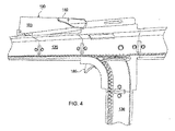
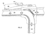
図4から図7を参照しながら、軌道110についてより詳細に説明する。
しかし、上述したように、図示の軌道110は、システムと共に使用可能な軌道にすぎない。
正確な構成は、用途に応じて様々であってもよく、上記のように、システム10は、軌道110を含んでいなくてもよい。
The
However, as mentioned above, the illustrated
The exact configuration may vary depending on the application, and as described above,
軌道110は、外壁152と、外壁152から平行に離間する内壁154とを含んでもよい。
さらに、軌道110は、内壁154と外壁152との間に延在している後壁160を含んでもよい。
図7からわかるように、外壁152と内壁154と後壁160とは、チャネルを形成する。
車両200の車輪220は、このチャネルに乗る。
The
Further, track 110 may include a rear wall 160 extending between
As can be seen from FIG. 7, the
軌道110は、駆動面156と、案内面158とを含んでもよい。
駆動面156は、車両200に積極的に係合して、車両200を軌道に沿って移動可能にする。
案内面158は、車両200を案内して、車両200と駆動面156との動作可能な係合を維持する。
本例では、駆動面156は、以下にさらに説明するように、車両200の車輪に係合するラックを形成する一連の歯で形成される。
案内面158は、ラック156に隣接する略平坦な面である。
ラック156は、軌道110の約半分に延在し、案内面158は、軌道110の残り半分に延在している。
図4から図7に示すように、ラック156は、軌道110の内壁154に形成されてもよい。
対向する外壁152は、内壁の案内面158に対して平行な略平坦な面であってもよい。
The
The
In this example, drive
The
The
As shown in FIGS. 4 to 7, the
The opposing
上述したように、軌道110は、上方の水平レール135と下方の水平レール140との間に延在している複数の垂直区間を含んでもよい。
いずれかの垂直区画といずれかの水平区画とが交差する軌道110の各区画に、交差部170が形成されてもよい。
各交差部170は、湾曲した内側分岐172と、略直線の外側分岐176とを含んでもよい。
垂直区画が下方レールと交差する部分は、同様の交差部170を含んでいるが、これらの交差部170は、反転している。
As mentioned above, track 110 may include a plurality of vertical sections extending between upper
An intersection 170 may be formed in each section of the
Each intersection 170 may include a curved inner branch 172 and a substantially straight outer branch 176.
The portions where the vertical sections intersect the lower rail include similar intersections 170, but these intersections 170 are inverted.
各交差部170は、滑らかに湾曲した内側レースと、軌道110の駆動面156の歯に対応する歯を備えた平坦な外側レースとを有する枢動可能なゲート180を含んでよい。
ゲート180は、第1の位置と、第2の位置との間で枢動してもよい。
第1の位置では、ゲート180は、閉じられ、ゲート180の直線状の外側レース184が交差部170の直線状の外側分岐176と揃う。
第2の位置では、ゲート180が開き、ゲート180の湾曲した内側レース182が、交差部170の湾曲した分岐172と揃う。
Each intersection 170 may include a
In the first position, the
In the second position, the
よって、閉位置では、ゲート180が下方に枢動して、ゲート180の外側レース184が駆動面156と揃う。
この位置では、ゲート180は、車両200が湾曲部で下方に曲がるのを阻止し、よって、車両200は、交差部170を直進する。
これに対し、図5に示すように、ゲート180が開位置に枢動した場合、ゲート180は、車両200が交差部170を直進するのを阻止する。
代わりに、ゲート180の湾曲した内側レース182が、内側分岐172の湾曲面と揃い、車両200は、交差部170で曲がる。
言い換えると、ゲート180が閉じている場合、交差部170の位置に応じて、車両200は、上方レール135又は下方レール135のいずれかに沿って交差部170を直進する。
ゲート180が開いている場合、交差部170の位置に応じて、ゲート180は、車両200を、垂直レール130から水平レール135に、又は、水平レール135から垂直レール130に送る。
Thus, in the closed position, the
In this position, the
In contrast, as shown in FIG. 5, when the
Instead, the curved inner race 182 of the
In other words, when the
When
上述した説明では、ゲート180により、車両200の1つが同じ方向(たとえば、水平方向)に進み続けるか、又は、一方向(たとえば、垂直方向)に曲がる。
ただし、一部の用途では、システム10は、垂直コラムと交差する3つ以上の水平レール135を含んでもよい。
そのような構成では、車両200を複数の方向に曲がらせる異なるレールを含むことが望ましい場合がある。
たとえば、車両200がコラムを下方に移動している場合、ゲート180によって車両200を水平レール135に沿って左方向又は右方向に曲がらせるか、又は、垂直コラムに沿って直進させることが可能であってもよい。
加えて、一部の例では、車両200は、上方に移動してもよい。
In the above description, the
However, for some applications,
In such a configuration, it may be desirable to include different rails that cause the
For example, if the
Additionally, in some examples,
システム10は、複数の車両200を含むため、車両200どうしが衝突しないように、車両200の位置が制御される。
実施形態では、システム10は、各車両200の位置を追跡し、各車両200に制御信号を提供して車両200の軌道110に沿った進行を制御する中央制御装置を使用する。
中央制御装置は、ゲート180など、軌道110に沿ったさまざまな要素の動作も制御してもよい。
あるいは、車両200が、ゲート180を動作してもよい。
図4から図5に示されるように、ゲート180は、車両200上のアクチュエータ230に応答する受動アクチュエータ190を含んでもよい。
車両200のアクチュエータがゲートアクチュエータ190に係合すると、ゲート180は、第1の位置から第2の位置に移動する。
例えば、図4に示すように、車両200を水平レール135に沿ったままにするために、ゲート180は、第1の位置をとる。
車両200のゲートアクチュエータ230が、ゲート180のアクチュエータ190に係合すると、ゲート180は、第2の位置に上向きに枢動し、車両200は、方向転換して垂直レール130に沿って下向きに移動する。
Since the
In an embodiment, the
The central controller may also control the operation of various elements along
Alternatively,
As shown in FIGS. 4-5,
When the actuator of
For example, as shown in FIG. 4,
When the
ゲート180上のアクチュエータ190は、リンケージによってゲート180に接続された、移動可能な作動面192であってもよい。
例えば、作動面192は、枢動可能なアーム193に取り付けられてもよい。
ゲート180を作動させて第1の位置から第2の位置に動かすために、車両200のゲートアクチュエータ230は、作動面192に接触する。
作動面192は、傾斜面の様に角度付き、車両200がゲート180に向かって前進すると、車両200のゲートアクチュエータが作動面192に係合し、アーム193を徐々に上方に移動させる。
アーム193は、リンケージによってゲート180に接続されてもよい。
したがって、アーム193が、枢動すると、ゲート180も枢動する。
このようにして、図4から図5に示すように、車両200のアクチュエータ230は、ゲート180上のアクチュエータと係合して、ゲート180を第1の位置から第2の位置に移動させる。
車両200が、図5に示すような開いたゲート180を通過した後、ゲート180は、図4に示す閉じた位置に戻ってもよい。
ゲート180は、付勢要素又はゲート180及び/もしくはアクチュエータの重量などにより、自動で閉じてもよい。
<運搬車両>
The actuator 190 on the
For example, the working surface 192 may be mounted on a pivotable arm 193.
To activate
The working surface 192 is angled like a sloped surface, and when the
Arm 193 may be connected to
Thus, when arm 193 pivots,
In this way, as shown in FIGS. 4 and 5, the
After the
<Transportation vehicle>
図3を参照して、運搬車両となる車両200の細部について詳細に説明する。
各運搬車両200は、車載電源を含む車載駆動システムを備えてもよい準自動型の車両である。
各車両200は、運搬用のアイテムの積み込み及び積み下ろしのための機構210も備えてもよい。
オプションで、各車両200は、ゲート180を選択的に作動させて車両200を選択的に方向転換させるゲートアクチュエータ230も備えてもよい。
With reference to FIG. 3, the detail of the
Each
Each
Optionally, each
車両200は、車両200へのアイテムの積み込みと、車両200からいずれかの容器へのアイテムの排出のためのさまざまな機構のいずれかを含んでもよい。
加えて、積み込み/積み下ろし機構210は、特定の用途向けに特別に調整されてもよい。
積み込み/積み下ろし機構210は、格納場所に格納されたアイテムに係合し、アイテムを車両200に引き込むように構成された移動可能要素を含んでもよい。
本例では、車両200は、格納場所50の格納コンテナ80に向かって移動するように構成された移動可能要素を含む。
格納コンテナ80に係合した後、移動可能要素は、格納場所50から離れ、それによって、格納コンテナ80を車両200に引き込む。
In addition, the loading /
The loading /
In this example,
After engaging the
本例では、積み込み/積み下ろし機構210は、移動可能なロッド又はバーからなる積み込み/積み下ろし要素212を含んでもよい。
バー212は、車両200の幅にまたがって延在し、車両200の側面に沿って延在している駆動チェーン214に両端が連結されていてもよい。
モーターが、駆動チェーン214を駆動して、この駆動チェーン214を格納場所50に向かう方向又は離れる方向に選択的に動かしてもよい。
たとえば、車両200が、格納場所に近づいて格納コンテナ80を取得する際、駆動チェーン214が、ロッドからなる積み込み/積み下ろし要素212を格納場所50に向けて駆動し、それによって、格納コンテナ80の底部83の溝又はノッチからなる保持溝88にバー212を係合させてもよい。
その後、駆動チェーン214は、反転し、それによって、バーからなる積み込み/積み下ろし要素212が格納場所50から移動する。
バーからなる積み込み/積み下ろし要素212は、格納コンテナ80のノッチ88に係合しているため、バー212が、格納場所50から離れるときに、バー212は、格納コンテナを車両200上に引っ張る。
これにより、積み込み/積み下ろし機構210は、アイテムを格納場所50から取得することができる。
同様に、アイテムを格納場所50に格納するには、積み込み/積み下ろし機構210の駆動チェーン214が、アイテムが格納場所50内に位置するまで、バー212を格納場所50に向けて駆動する。
その後、車両200は、下方に移動してバー212を格納コンテナ80から係合解除し、それによって、格納コンテナを解放してもよい。
あるいは、積み込み/積み下ろし機構210は、ノッチ88との係合を外して、バー212が下方に駆動されるように構成されてもよい。
In this example, the loading /
The
A motor may drive the
For example, as the
The
The bar loading /
Thus, the loading /
Similarly, to store an item in the
Thereafter, the
Alternatively, the loading /
加えて、システム10は、軌道110の前方側に隣接する格納場所50の配列と、軌道110の後方側に隣接する格納場所50の第2配列とを備えているため、積み込み/積み下ろし機構210は、前方側の配列と後方側の配列内の格納コンテナ80を取得及び格納するように動作可能である。
詳細には、図3に示すように、積み込み/積み下ろし機構210は、相互に離間した2本のバー212を含む。
一方のバー212は、前方の配列の格納コンテナ80と係合可能な一方で、第2のバー212は、格納場所50の後方の配列の格納コンテナ80と係合可能である。
In addition, the
In particular, as shown in FIG. 3, the loading /
One
車両200は、車両200を軌道110に沿って移送するために使用される4つの車輪220を備えてもよい。
車輪220は、2つの車輪が車両200の前端に沿って設置され、2つの車輪が車両200の後端に沿って設置されるように、2本の平行に離間した軸215に取り付けられてもよい。
The
車両200は、車輪220を駆動する車載モーターを備えてもよい。
より詳細には、駆動モーターは、軸215に動作可能に連結されて軸を回転させ、それによって車輪220の歯車222を回転させてもよい。
車両200の駆動システムは、車両200を軌道110に沿って同期的に駆動するように構成されてもよい。
本例では、駆動システムは、各歯車222が同期的な態様で駆動されるように構成されている。
More specifically, a drive motor may be operatively connected to
The drive system of
In this example, the drive system is configured such that each
車両200は、車両200を駆動するために必要な電力を提供するレール沿いの接触子などの、外部の電源により動かすこともできる。
しかし、本例では、車両200は、駆動モーターと積み込み/積み下ろし機構210を駆動するモーターとの両方に必要な電力を提供する車載電源を備える。
さらに、本例では、電源は、再充電可能である。
電源は、再充電可能な電池等の電源を含んでもよいが、本例では、電源は、1つ又は複数のウルトラキャパシタで構成される。
ウルトラキャパシタは、きわめて高いアンペア数を受け入れて再充電できる。
高い電流を使用することで、ウルトラキャパシタを数秒以下等の極めて短い時間で再充電できる。
However, in this example,
Further, in this example, the power supply is rechargeable.
The power source may include a power source such as a rechargeable battery, but in this example, the power source is comprised of one or more ultracapacitors.
Ultracapacitors can accept and recharge very high amps.
By using a high current, the ultracapacitor can be recharged in a very short time, such as several seconds or less.
車両200は、電源を再充電するための1つ又は複数の接触子を含む。
本例では、車両200は、外側に付勢されるようにばね加圧された銅ブラシ等の複数のブラシを含む。
ブラシは、充電レールと連動して、電源を再充電する。
In this example, the
The brush works in conjunction with the charging rail to recharge the power supply.
各車両200は、アイテムが車両200上に積み込まれたことを検出する積み込みセンサを含んでもよい。
この積み込みセンサを使用することで、アイテムが車両200に適切に配置されているかどうかを検出可能である。
たとえば、積み込みセンサは、重量の変化を検出する力検出器又はアイテムの存在を検出する赤外線センサを含んでもよい。
Each
By using this loading sensor, it is possible to detect whether the item is properly arranged in the
For example, a stow sensor may include a force detector that detects a change in weight or an infrared sensor that detects the presence of an item.
車両200は、システムの中央プロセッサから受信した信号に応じて車両200の動作を制御するプロセッサをさらに含んでもよい。
さらに、車両200は、車両200が軌道110に沿って移動する際に中央プロセッサと継続的に通信できるようにする無線トランシーバを含んでもよい。
あるいは、一部の用途では、軌道沿いに配置された複数のセンサ又は指示器を組み込むことが望ましい場合がある。
車両200は、センサ信号及び/又は指示器を感知する読み取り装置と、センサ又は指示器に応じて車両200の動作を制御する中央プロセッサとを含んでもよい。
<採取所と軌道>
Further,
Alternatively, for some applications, it may be desirable to incorporate multiple sensors or indicators located along the track.
<Sampling station and track>
前述のように、システム10は、車両200が格納場所50からアイテムを取得し、アイテムを採取所300に移送するように構成されてもよい。
ここで、図1から図2を参照して、採取所300をより詳細に説明する。
As described above, the
Here, the
システム10は、注文の履行に必要なアイテムを取得するために使用される。
注文は、異なる部署での製造工程に必要な部品等の内部注文である場合や、顧客に対して履行及び出荷される顧客注文である場合がある。
いずれの場合も、システム10は、格納領域からアイテムを自動的に取得し、採取所300にアイテムを運んで、動作者が必要な数のアイテムを格納コンテナ80から採取できるようにする。
アイテムが格納コンテナ80から採取された後、車両200は前進し、注文に必要な次のアイテムを前進させる。
システム10は、この態様で動作を継続して、動作者が注文に必要なすべてのアイテムを採取できるようにする。
The order may be an internal order for parts or the like required for a manufacturing process in a different department, or a customer order fulfilled and shipped to a customer.
In either case, the
After the items have been removed from the
The
本例では、採取所300は、格納場所50の配列の一端に配置される。
しかし、複数の採取所300を軌道110に沿って配置するのが望ましい場合がある。
たとえば、第2採取所300を、格納場所50の配列の他端に沿って配置することができる。
あるいは、複数の採取所300を一端に設けることもできる。
例えば、第2採取所300が、通路20の一端の第1採取所300の上に位置していてもよい。
In this example, the
However, it may be desirable to arrange
For example, the
Alternatively, a plurality of
For example, the
採取所300は、車両200が上方に移動して動作者に中身を提示し、それによって、動作者が格納コンテナ80からアイテムを容易に取得できるように構成されていてもよい。
図1から図2を参照すると、採取所300では、上方に湾曲して動作者から離間する湾曲区画315が軌道110に含まれている。
これにより、車両200は、上方に移動し、動作者が格納コンテナ80からアイテムを取り出しやすい高さで停止する。
動作者が格納コンテナ80からアイテムを取り出した後、車両200は、横方向で動作者から離れ、垂直方向で上方の水平レール135に向けて移動する。
The
Referring to FIGS. 1-2, at the
Thereby, the
After the operator removes the item from the
システムは、車両200が採取所300で傾斜し、それによって、動作者が格納コンテナ80からアイテムを取得しやすくするように構成可能である。
たとえば、車両200が、採取所300に近づいたときに、制御装置で、前方の車輪220が停止した後も後方の車輪220が移動し続けるように車両200を制御できる。
これにより、(動作者の視点で)車両200の後端が持ち上がる。
動作者が、アイテムを格納コンテナ80から採取した後、(動作者に対して)前方の車輪220が、まず、移動して、車両200を水平にする。
水平になった後、4つの車輪220は、同期して駆動する。
The system can be configured such that the
For example, when
This raises the rear end of the vehicle 200 (from the point of view of the operator).
After the operator has removed the item from the
After leveling, the four
車両200の動作を制御することにより車両200を傾けることが可能であるが、車両200の車輪が、上述したように軌道110の歯にかみ合う歯付き車輪220のように、軌道110の駆動要素にしっかりと噛み合っている場合、後方車輪220が前方車輪220と異なる速度で駆動されると、車輪220が動かなくなる可能性がある。
よって、軌道110が、移動して格納コンテナを動作者の方へ傾けるように、軌道システムを改良してもよい。
It is possible to tilt the
Thus, the track system may be modified such that the
図1及び図2を参照して、採取所300における軌道システムの詳細について、より詳しく説明する。
格納場所50のコラムの端部で、軌道110は、システムの垂直コラムから外側に向けて湾曲し、採取所300の湾曲軌道315を形成する。
採取所300のこの軌道区画は、車両200の前方の軸215を支持及び案内する平行な前方軌道区画と、車両200の後方の軸215を支持及び案内する平行な後方軌道区画と、を含む。
前方軌道区画は、上方に垂直に延在し、次に湾曲して格納場所の垂直コラムに戻る。
後方軌道区画は、前方軌道区画と実質的に平行であり、前方軌道区画と実質的に同じように湾曲する。
これにより、前方軌道区画及び後方軌道区画は、車両200が湾曲軌道315に沿って移動するときに実質的に水平な向きを維持できるように車両200を案内する。
With reference to FIG. 1 and FIG. 2, the details of the track system in the
At the end of the column of the
This track section of the
The forward track section extends vertically upward and then curves back to the vertical column of the storage location.
The rear track section is substantially parallel to the front track section and curves substantially the same as the front track section.
Thereby, the front track section and the rear track section guide the
後方軌道区画は、車両200が採取所300で停止している間に、車両200の後方の軸を上昇させることができるように構成されてもよい。
車両200の後方の軸を上昇させることで、車両200の格納コンテナ80が傾斜して、動作者の採取作業を容易にするように格納コンテナの中身が提示される。
The rear track section may be configured to allow the rear axle of the
By raising the axle behind the
採取所300は、採取所300の効率を向上させるために、複数のアイテムを備えてもよい。
たとえば、採取所300は、動作者を支援するために、情報を表示するモニタを備えてもよい。
車両200が採取所300に近づくときに、システム10は、注文に対して格納コンテナ80から取得する必要があるアイテムの数などの情報を表示してもよい。
加えて、動作者は複数の注文のアイテムを取得する場合があるため、システムは、各注文に対して取得する必要があるアイテムの数に加えて、取得するアイテムの対象の注文を表示してもよい。
さらに、システムは、動作者が適切な数のアイテムを格納コンテナから取得した後に格納コンテナに残っているべきアイテムの数などの情報もまた表示してもよい。
The
For example, the
As the
In addition, because an operator may retrieve items for multiple orders, the system will display the number of items that need to be retrieved for each order, plus the target order for the items to retrieve. Is also good.
Further, the system may also display information such as the number of items that should remain in the storage container after the operator has obtained an appropriate number of items from the storage container.
上述したシステムの利点の1つは、車両200が(上方レール又は下方レールに沿った)水平移動から(コラムのいずれかを下降する)垂直移動に移行する際に、車両200の向きが実質的に変わらないことである。
詳細には、車両200が水平に移動しているとき、前方の2つの歯付き車輪220は、前方軌道115の上方水平レール135又は下方水平レール140と連携し、後方の2つの歯付き車輪220は、後方軌道120の対応する上方レール135又は下方レール140と連携する。
車両200がゲートを通過してコラムに入ると、前方の2つの歯付き車輪220が、前方軌道115の一対の垂直区間130と係合し、後方の2つの歯付き車輪が、後方軌道120の対応する垂直区間と係合する。
なお、車両200の水平方向に対する向きが変化しないというのは、車両200が軌道110に沿って移動することを意味している。
車両200は、採取所300で水平方向に対して傾斜していても、軌道110に沿って移動する際は、水平方向に対して実質的に一定の向きを維持するといえる。
One of the advantages of the system described above is that when the
Specifically, when the
As the
The fact that the orientation of the
Even when the
車両200が、上方水平レール135又は下方水平レール140から垂直コラムへ、又は垂直コラムから上方水平レール135又は下方水平レール140へ移動するとき、軌道110は、4つの歯付き車輪220のすべてを同じ高さに位置させる。
これにより、車両200が、軌道110を移動して水平移動と垂直移動とを移行するときに、歪んだり傾斜したりしない。
加えて、車両200を単一の軸と共に構成するのが望ましい場合がある。
そのような構成では、車両200は、上述した実質的に水平な向きではなく、実質的に垂直な向きになる。
単一軸の構成では、車両200の重量により、車両200の向きが維持される。
ただし、単一軸の車両200を使用する場合、格納場所50の向きは、車両200の垂直の向きに合わせて再構成される。
<動作>
When the
Thereby, when the
In addition, it may be desirable to configure the
In such a configuration, the
In a single axis configuration, the weight of the
However, when using the single-
<Operation>
中央制御装置が、アイテムの適切な格納場所50を決定すると、採取所300を離れる車両200の経路が決定されてもよい。
具体的には、中央制御装置は、車両200の経路を決定し、アイテムの配送先の格納場所50に関する情報を車両200に伝えてもよい。
次に、中央制御装置は、車両200の動作を制御し、アイテムの配送先となる格納場所50に車両200を向かわせるために必要になる、軌道110に沿うゲート180を動作させる。
車両200が適切な格納場所50に到着すると、車両200は、格納場所50で停止し、格納コンテナ80は、適切な格納場所50に移動する。
例えば、車両200が適切な格納場所50で停止し、車両200上の車載コントローラが、バー212を前進させる駆動チェーン214を駆動する適切な信号を車両200に送ってもよい。
バー212は、格納コンテナ80のスロット88に係合するので、バー212は、格納コンテナ80を車両200から離れる方向に駆動し、適切な格納場所50へと駆動する。
Once the central controller has determined the
Specifically, the central control device may determine the route of the
Next, the central controller controls the operation of the
When the
For example,
As the
アイテムを排出した後、車両200は、第2格納場所に移動して、採取所300に運ぶ次のアイテムを取得してもよい。
アイテムを取得した後、車両200は、コラムの垂直区間130を下方に移動して下方レール140に到達してもよい。
ゲート180が、車両200を下方レール140に沿って送ってもよく、車両200は、下方レール140をたどって採取所300に戻って別のアイテムを配送してもよい。
After discharging the item, the
After acquiring the item, the
車両200が空の格納場所に格納コンテナ80を配送する場合、車両200は、上述のように動作する。
同様に、別の格納コンテナ80に接続されていない格納コンテナ80を車両200が取得する場合にも、車両200は、上述のように動作する。
具体的には、車両200は、格納コンテナに隣接して停止する。
積み込み/積み下ろし機構210が前進して格納コンテナ80と係合した後、格納コンテナ80を車両200上に引き寄せる。
反対に、既に、格納コンテナ80を収容している格納場所50に置かれる格納コンテナ80を車両200が運ぶ場合、車両200の動作は、変更される。
同様に、車両200が遠隔の格納場所50の格納コンテナ80に接続されている格納コンテナ80を取得中である場合、車両200の動作は変更される。
When the
Similarly, also when the
Specifically, the
After the loading /
Conversely, if the
Similarly, if the
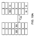
ここで、図9及び図10Aから図10Hを参照して、格納コンテナ「n」個分の奥行きを有する格納場所50から格納コンテナ80を取得する際の車両200の動作について、説明する。
図9は、格納コンテナ80の2つの格納ラック35、格納ラック40が示されている実施形態を示す。
格納ラック35、40は、通路20によって互いに隔てられており、車両200は、格納ラック35、格納ラック40間の空間内を移動する。
図示の実施形態では、格納ラックは、2つの格納コンテナ80を格納するのに充分な奥行きを有する格納場所50を含む。
格納コンテナ80を収容する格納場所50の、通路20に隣接する部分を、この説明では、内側セルと呼び、55で示す。
内側セル55の背後の格納場所50の部分を、遠隔セルと呼び、57で示す。
Here, with reference to FIGS. 9 and 10A to 10H, an operation of the
FIG. 9 shows an embodiment in which two
The storage racks 35 and 40 are separated from each other by the
In the illustrated embodiment, the storage rack includes a
The portion of the
The portion of the
図示された実施形態では、格納コンテナ80A、80Bは、格納コンテナ80の前端部に接続された前方コネクタ92と、格納コンテナ80の後端部に接続された後方コネクタ96とを含む。
遠隔セル内の格納コンテナ80Bの前方コネクタ92は、内側セル内の格納コンテナ80Aの後方コネクタ96と接続して、90で示される解放可能な接続を形成する。
In the illustrated embodiment,
The
図9では、格納コンテナ80Bは、内側セルに格納されている格納コンテナ80Aの後ろの遠隔セルに格納されている。
格納コンテナ80A、格納コンテナ80Bは、コネクタ90などのコネクタによって互いに解放可能に接続されている。
格納コンテナ80Aと格納コンテナ80Bとは、水平方向から見て全般的に整列している。
車両200は、第1の格納コンテナ80Aを収容している格納場所50に隣接する位置で停止する。
車両200は、空である(すなわち、車両200には格納コンテナ80が搭載されていない)。
積み込み/積み下ろし機構210は、図9に示されるように、格納コンテナ80Aに係合する。
例えば、図11及び図12に示されるように、格納コンテナ80の前端部は、軌道(例えば、垂直軌道区間130)を越えて通路20内に延在してもよい。
具体的には、格納コンテナ80の輸送溝88は、通路20内に延在してもよい。
積み込みバー212は、積み込みバー212が輸送溝88に挿入されるまで、車両200のプラットフォームから離れて、格納コンテナ80に向かって外向きに延伸する。
In FIG. 9, the
The
The
The
The
The loading /
For example, as shown in FIGS. 11 and 12, the front end of the
Specifically, the transport channel 88 of the
The
図10Aを参照すると、積み込み機構210は、格納コンテナ80Aを車両200上に引っ張る。
内側セルの格納コンテナ80Aが車両200上に引っ張られると、格納コンテナ80Aは、遠隔セルの第2の格納コンテナ80Bを内側セルに向かって引っ張る。
具体的には、コネクタ90が、内側セルの格納コンテナ80Aと遠隔セルの格納コンテナ80Bとを接続しているので、格納コンテナは、共に水平に移動する。
Referring to FIG. 10A, the
When the inner
Specifically, since the
図10Bを参照すると、格納コンテナ80Aが、その上部の格納場所内の格納コンテナ80から離れるまで、車両200は、格納コンテナ80Aを車両200のプラットフォーム上に移動し続ける。
格納コンテナ80Aが移動することで、遠隔の格納コンテナ80Bが内側セル内に引き込まれる。
その結果、格納ラック内で格納コンテナ80Aが占めていた場所を、格納コンテナ80Bが占めるようにする。
図10Bでは、格納コンテナ80Bを内側セルに引き込むことにより、格納コンテナ80Bの背後の遠隔セル57が空になっていることが分かる。
Referring to FIG. 10B,
As the
As a result, the
In FIG. 10B, it can be seen that the
上述のように、車両200の積み込み機構210は、内側の格納コンテナ80Aを車両200上に積み込み、次に、遠隔の格納コンテナ80Bが異なる格納場所(この場合は、内側セル)に移動するまで遠隔の格納コンテナ80Bを水平に移動させる。
格納コンテナ80Aを車両200上に移動し続けると、2つの格納コンテナ80A、格納コンテナ80Bは、接続されたままであるため、格納コンテナ80Bを通路内に、場合によっては、車両200上に引き込む。
したがって、格納コンテナ80Bを新しい格納場所(すなわち内側セル)に移動すると、解放可能な接続90を切り離し、それにより、2つの格納コンテナ80A、格納コンテナ80Bが切り離される。
As described above, the
If the
Thus, moving
格納コンテナ80A、格納コンテナ80Bは、これらの格納コンテナ80A、80Bを相互接続する機構に応じて、さまざまな方法で切り離されてもよい。
前述のように、コネクタ92、コネクタ96は、2つの格納コンテナ80A、80Bの間の解放可能な接続を提供するさまざまなコネクタのいずれでもよい。
コネクタは、機械式でも電気機械式でもよい。
例えば、コネクタ92、コネクタ96は、磁気素子であってもよく、その一方は、電磁石を含んでもよい。
電磁石は、消磁して格納コンテナ80A、80Bを切り離すことで、格納コンテナ80Bに対する格納コンテナ80Aの相対運動を容易にしてもよい。
あるいは、上述のように、コネクタ92、コネクタ96は、一対のフック又は舌部と溝部による構成などの機械的コネクタであってもよい。
したがって、格納コンテナ80A、格納コンテナ80Bを切り離すために、コネクタ92、コネクタ96の係合が解除される。
実施形態では、格納コンテナ80の1つを他の格納コンテナ80に対して垂直に変位させることにより、コネクタ92、コネクタ96の係合が解除される。
The
As mentioned above, the
The connector may be mechanical or electromechanical.
For example,
The electromagnet may be demagnetized to separate the
Alternatively, as described above, the
Therefore, the engagement between the
In the embodiment, by displacing one of the
図10Cを参照すると、格納コンテナ80Aが車両200上に積み込まれ、格納コンテナ80Aが、コラム内の直上又は下の格納コンテナ80から離れると、格納コンテナ80Aは、垂直に移動して格納コンテナ80Aを格納コンテナ80Bから切り離す。
図13から図14に示されるように、コネクタ92Bの舌部94Bは、コネクタ96Aの溝98A内に下向きに突出してもよい。
したがって、図14に示すように、コネクタ92Bの舌部94Bが、溝98Aから外れるまで、車両200は、下方に移動して格納コンテナ80Aを垂直方向下方に移動させる。
このように、車両200を変位させると、格納コンテナ80Aが、格納コンテナ80Bから垂直方向に切り離される。
コネクタ92、コネクタ96は、車両200を下降させるのではなく、車両200を上方に移動させることによりコネクタを切り離すように、異なる構成が可能であることを理解されたい。
Referring to FIG. 10C, when the
As shown in FIGS. 13 and 14, the tongue 94B of the connector 92B may project downward into the groove 98A of the
Therefore, as shown in FIG. 14, the
As described above, when the
It should be understood that the
ここで、図10Dを参照すると、格納コンテナ80Aが、格納コンテナ80Bから切り離された後、格納コンテナ80Aは、格納コンテナ80Bから離れて車両200上で水平に移動する。
車両200が、コラム内で垂直方向に上下に移動するときに、格納コンテナ80が、格納ラック内の車両200のいずれにも干渉又は係合しないように、格納コンテナ80Aは、通路20内の中央にくるまで水平に移動する。
格納コンテナ80Aが、車両200に完全に搭載されると、車両200は、採取所300又は他の輸送場所に、又は、異なる格納場所に進んでもよい。
例えば、車両200は、下方水平レールまで下降し、次に水平レールに沿って移動することで、格納コンテナ80Aを採取所300に配送してもよい。
あるいは、格納コンテナ80Aを別の格納場所に移送し、その格納場所に積み下ろしてもよい。
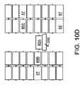
Here, referring to FIG. 10D, after the
When the
Once the
For example, the
Alternatively, the
車両200上の格納コンテナ80Aを、格納コンテナ80Cが位置する格納場所に積み下ろすステップの詳細が、図10Eから図10Hに関連して、以下に説明される。
車両200は、格納コンテナ80Cが格納されている格納ラック40の内側セルに隣接する位置に移動する。
格納コンテナ80Aは、車両200から格納コンテナ80Cに積み下ろされる。
格納コンテナ80Aが積み下ろされると、格納コンテナ80Aは、格納コンテナ80Cを格納ラック内の格納場所のより奥に押し込む。
そうすることにより、格納コンテナ80Cが内側セルから遠隔セル57に水平に移動する。
格納コンテナ80Aを下ろし、格納コンテナ80Cを移動させるプロセスの間、格納コンテナ80Aは、格納コンテナ80Cに接続される。
前述のように、2つの格納コンテナ80A、80Cのコネクタは、さまざまな方法で接続されてもよい。
本例では、格納コンテナ80A、80Cは、格納コンテナ80の一方を他方に対して移動することで接続される。
具体的には、格納コンテナ80Aが格納コンテナ80Cに対して垂直に変位することで、2つの格納コンテナ80A、80Cを接続する。
The details of loading and unloading the
The
The
When the
By doing so, the
During the process of lowering
As described above, the connectors of the two
In this example, the
Specifically, the two
再び、図10Eを参照すると、格納コンテナ80Aを積み下ろすために、格納コンテナ80Aが格納コンテナ80Cよりも垂直に高く配置されるまで、車両200は、軌道に沿って移動する。
具体的には、格納コンテナ80Aの前方コネクタ92が格納コンテナ80Cの後方コネクタ96の上に位置するように、車両200は、格納コンテナ80に隣接する位置に駆動される。
次に、図10Fに示すように、格納コンテナ80Aを格納コンテナ80Cに向かって水平に移動させることで、車両200から格納コンテナ80を部分的に積み下ろす。
本例では、格納コンテナ80Aの前方コネクタ92が格納コンテナ80Cの後方コネクタ96に倣うまで、格納コンテナ80Aを移動する。
具体的には、車両200の積み下ろし機構210は、前方コネクタ92の舌部94が格納コンテナ80Cの後方コネクタ96の溝98に倣うまで、格納コンテナ80Aを水平方向に移動させる。
Referring again to FIG. 10E, to unload
Specifically,
Next, as shown in FIG. 10F, the
In this example, the
Specifically, the loading /
格納コンテナ80Aと格納コンテナ80Cのコネクタが位置合わせされると、車両200は、格納コンテナ80を接続するために垂直に移動する。
具体的には、図10Gを参照すると、車両200は、下方に移動することで、格納コンテナ80Aと格納コンテナ80Cとを水平方向に整列させ、2つの格納コンテナ80A、80Cを相互接続する。
格納コンテナ80Aが、格納場所と水平に整列すると、図10Hに示すように、格納コンテナ80Aは、車両200から格納場所に積み下ろされる。
例えば、本実施形態では、車両200の積み込み/積み下ろし機構210は、第1格納コンテナ80Aを車両200から動かし、第3格納コンテナ80Cが配置されていた内側セルに移動させる。
格納コンテナ80Aを内側セル内に移動させると、格納コンテナ80Aは、格納コンテナ80Cを格納場所の奥に押し込み、格納コンテナ80Cが(図10Gに57で示される)遠隔セル内に移動する。
When the connectors of the
Specifically, referring to FIG. 10G,
When the
For example, in the present embodiment, the loading /
When the
上述のように、格納コンテナ80Aは、格納コンテナ80Cに隣接する位置に移動される。
そして、格納コンテナ80Aを格納ラックに積み下ろす前に、2つの格納コンテナ80A、80Cを接続する。
このようにして、その後、格納コンテナ80Aが取得される際、遠隔セル内の格納コンテナ80Cを通路20に向かって引っ張ることが可能になるように、格納コンテナ80A、80Cは、接続される(例えば、図10Aから図10D及び上記の説明を参照)。
しかしながら、格納コンテナ80Aを積み下ろして格納コンテナ80Cを遠隔セルに移動するために格納コンテナ80を接続する必要がないことを理解すべきである。
具体的には、格納コンテナ80Aが、格納コンテナ80Cを後方セルに後方に押し込むので、格納コンテナ80Aを積み下ろす前に格納コンテナ80を接続する必要はない。
したがって、前方コネクタ92と後方コネクタ96の構成によっては、第1格納コンテナ80Aが車両200から積み下ろされた後に、格納コンテナ80が互いに接続される場合がある。
As described above, the
Then, before unloading the
In this manner, the
However, it should be understood that it is not necessary to connect
Specifically, since the
Therefore, depending on the configuration of the
したがって上述のように、システムは、複数奥行きの格納場所を組み込むように構成されてもよい。
複数奥行きの格納場所では、複数の格納コンテナ80が共通の水平格納場所で、前後に格納される。
共通の水平格納場所にある格納コンテナ80は、相互接続されてもよく、共通の格納場所にある格納コンテナ80の1つを取得すると、共通の格納場所にある他の格納コンテナ80が車両200に向かって前方に移動する。
上述の説明では、格納コンテナ80Aが運搬車両上に積み込まれ、それにより、格納コンテナ80を遠隔セルから内側セルに引き込むことで、その格納コンテナ80が内側セルから取得可能になる動作を説明した。
その後、車両200は、格納コンテナ80Aを別の格納場所に配送し、その後に戻って内側セルに移動した格納コンテナ80Bを取得可能である。
あるいは、特定の例では、(図9に示す格納コンテナ80A及び格納コンテナ80Bのような)2つの格納コンテナ80A、80Bを収容する格納場所は、その2つの格納コンテナ80と垂直及び水平に整列した空の格納場所の向かい側に位置してもよい。
そのような場合、格納コンテナ80Aは、車両200上に積み込まれ、それにより、格納コンテナ80Bを車両200に引っ張ってもよい。
上述のように、2つの格納コンテナ80を切り離すのではなく、格納コンテナ80Aをさらに水平方向に移動させて、格納コンテナ80を対向する格納ラックの格納場所に積み下ろす。
格納コンテナ80Aが、格納場所に積み下ろされると、格納コンテナ80Bが、車両200上に引っ張られる。
次に、車両200が、採取所又は別の格納場所に格納コンテナ80Bを配送できるように、格納コンテナ80Bを格納コンテナ80Aから切り離すことができる。
たとえば、車両200を垂直方向に移動して、格納コンテナ80Bを格納コンテナ80Aから切り離すことができる。
Thus, as described above, the system may be configured to incorporate multiple depth storage locations.
In a storage location with a plurality of depths, a plurality of
The
In the above description, the operation has been described in which the
After that, the
Alternatively, in a particular example, a storage location containing two
In such a case, the
As described above, instead of separating the two
When the
The
For example, the
前述の説明では、格納コンテナ80が複数奥行きの格納場所に格納されるシステムについて説明した。
遠隔セル内の格納コンテナ80の前にある格納コンテナ80を最初に取得する車両200によって、複数奥行きの格納場所の遠隔の格納コンテナ80が取得されてもよい。
取得された格納コンテナ80は、その後、車両200によって移送される。
取得された格納コンテナ80は、次に別の場所に格納され、車両200が戻って来て遠隔セルにあった格納コンテナ80を取得可能であってもよい。
あるいは、第1車両が遠隔セル内の格納コンテナ80の前にある格納コンテナ80を取得し、第2車両が来て、遠隔セル内に位置していた格納コンテナ80を取得してもよい。
In the above description, a system in which the
A
The obtained
The acquired
Alternatively, the first vehicle may acquire the
本発明の広範な発明概念から逸脱することなく、上述の実施形態に変更又は修正を加えることができる。
したがって、本発明は、本明細書に記載の実施形態に限定されず、特許請求の範囲に記載の内にあるすべての変更及び修正を含む。
Changes or modifications may be made to the above-described embodiments without departing from the broad inventive concept of the present invention.
Accordingly, the invention is not limited to the embodiments described herein, but includes all changes and modifications that fall within the scope of the appended claims.
Claims (30)
アイテムを配送及び取得する車両を駆動させる車載モーターを含む、複数の独立動作可能な車両と、
前記複数の独立動作可能な車両を案内する軌道と、
垂直方向に互いに離れて位置して前記軌道に沿って配置されていることで前記軌道が前記複数の独立動作可能な車両を該複数の格納場所に案内するように構成されている複数の格納場所と、
各格納場所が該複数の格納コンテナを収容するように構成される複数の格納コンテナと、を備え、
前記複数の格納コンテナの1つ目である第1格納コンテナが、第1端部に第1コネクタを含み、
前記複数の格納コンテナの2つ目である第2格納コンテナが、第2端部に第2コネクタを含み、
前記第2コネクタが前記第1コネクタに解放可能に接続されることで、前記複数の格納場所の1つで前記第1格納コンテナと前記第2格納コンテナとが解放可能に接続され、
各独立動作可能な車両が、該各独立動作可能な車両と前記複数の格納場所の一つとの間で前記第1格納コンテナと前記第2格納コンテナとを輸送する、輸送機構を含み、
前記輸送機構が前記第1格納コンテナを移動する際に、前記第1格納コンテナと前記第2格納コンテナとの間の前記解放可能な接続が、前記第2格納コンテナを移動するように動作可能である、自動格納及び取得システム。 An automatic storage and retrieval system that defines a plurality of storage locations for containing items,
A plurality of independently operable vehicles, including an in-vehicle motor that drives a vehicle that delivers and acquires items;
A track for guiding the plurality of independently operable vehicles;
A plurality of storage locations arranged vertically along the track at a distance from each other so that the track guides the plurality of independently operable vehicles to the plurality of storage locations; When,
A plurality of storage containers, wherein each storage location is configured to house the plurality of storage containers,
A first storage container that is the first of the plurality of storage containers includes a first connector at a first end;
A second storage container that is a second one of the plurality of storage containers includes a second connector at a second end;
When the second connector is releasably connected to the first connector, the first storage container and the second storage container are releasably connected at one of the plurality of storage locations,
Each independently operable vehicle includes a transport mechanism for transporting the first storage container and the second storage container between each independently operable vehicle and one of the plurality of storage locations;
When the transport mechanism moves the first storage container, the releasable connection between the first storage container and the second storage container is operable to move the second storage container. There is an automatic storage and retrieval system.
互いに離れて配置されて全般的に水平方向に延在する複数の水平軌道区画と、
互いに離れて配置されて全般的に垂直方向に延在するとともに前記水平軌道区画と交差して環状経路を形成する複数の垂直軌道区画と、
前記水平軌道区画の1つが前記垂直軌道区画の1つと交差するとともに全般的に水平方向の第1経路と全般的に垂直方向の第2経路とを提供する交差部と、
を備えている、請求項1に記載の装置。 The orbit is
A plurality of horizontal track sections disposed apart from each other and extending generally horizontally;
A plurality of vertical track sections spaced apart from each other and extending generally vertically and intersecting the horizontal track sections to form an annular path;
An intersection where one of the horizontal track sections intersects one of the vertical track sections and provides a first generally horizontal path and a second generally vertical path;
The device of claim 1 comprising:
前記第2コネクタが、前記舌部を収容するように構成される溝部を備えている、請求項1乃至請求項6のいずれかに記載の装置。 The first connector comprises a tongue;
Apparatus according to any of the preceding claims, wherein the second connector comprises a groove configured to receive the tongue.
前記第1格納コンテナが、前記第2格納コンテナの前に配置されている、請求項1乃至請求項7のいずれかに記載の装置。 The plurality of storage locations where the first storage container and the second storage container are located are configured to accommodate the first storage container and the second storage container in a horizontal direction.
Apparatus according to any of the preceding claims, wherein the first storage container is located in front of the second storage container.
前記第1格納コンテナ及び前記第2格納コンテナのそれぞれが、長さを有し、
前記複数の格納場所の奥行きが、前記第1格納コンテナと前記第2格納コンテナとの合計の長さと少なくとも同じ長さを有している、請求項1乃至請求項9のいずれかに記載の装置。 The storage location has a depth,
Each of the first storage container and the second storage container has a length,
Apparatus according to any of the preceding claims, wherein the depth of the plurality of storage locations has at least the same length as the total length of the first storage container and the second storage container. .
前記第1格納ラックと前記第2格納ラックとの間に通路が、形成されている、請求項1乃至請求項11のいずれかに記載の装置。 The plurality of storage locations comprises a first storage rack at a storage location located away from a second storage rack at the storage location;
The apparatus according to claim 1, wherein a passage is formed between the first storage rack and the second storage rack.
前記複数の独立動作可能な車両が、格納コンテナを前記採取所に配送し、
動作者が、前記採取所で前記格納コンテナからアイテムを取得可能である、請求項12に記載の装置。 A sampling station is located at the end of the passage;
The plurality of independently operable vehicles deliver a storage container to the collection site;
13. The apparatus of claim 12, wherein an operator can obtain items from the storage container at the collection site.
前記第1格納ラックと前記第2格納ラックとが、前記格納コンテナが前記軌道を越えて前記通路内に水平に突出するように前記軌道に対して位置している、請求項14に記載の装置。 The plurality of independently operable vehicles includes drive wheels that engage the track.
15. The apparatus of claim 14, wherein the first storage rack and the second storage rack are positioned relative to the track such that the storage container projects horizontally beyond the track into the passage. .
アイテムを配送及び取得する各車両が該各車両を駆動させる車載モーターを含む複数の車両と、
格納場所の第1格納ラックと、
前記第1格納ラックから離れて位置するとともに前記第1格納ラックと該第2格納ラックとの間に通路を有して前記複数の車両が前記通路内を垂直方向と水平方向とに移動可能である格納場所の第2格納ラックと、
各格納場所が複数の格納コンテナを収容するように構成される複数の格納コンテナと、を備え、
前記複数の格納コンテナの1つ目である第1格納コンテナが、第1端部に第1コネクタを含み、
前記複数の格納コンテナの2つ目である第2格納コンテナが、第2端部に第2コネクタを含み、
前記第1コネクタが前記第2コネクタに解放可能に接続されることで、前記格納場所の1つで前記第1格納コンテナと前記第2格納コンテナとが解放可能に接続され、
各車両が、該各車両と前記複数の格納場所の一つとの間で前記第1格納コンテナと前記第2格納コンテナとを輸送する輸送機構を含み、前記輸送機構が前記第1格納コンテナを移動する際に、前記第1格納コンテナと前記第2格納コンテナとの間の前記解放可能な接続が、前記第2格納コンテナを移動するように動作可能である、材料取り扱いシステム。 A material handling system for storing or acquiring a plurality of items,
A plurality of vehicles, each vehicle delivering and acquiring the item including an in-vehicle motor that drives each vehicle;
A first storage rack at the storage location;
The plurality of vehicles are located apart from the first storage rack and have a passage between the first storage rack and the second storage rack, and the plurality of vehicles can move vertically and horizontally in the passage. A second storage rack at a storage location;
A plurality of storage containers, each storage location configured to accommodate a plurality of storage containers;
A first storage container that is a first of the plurality of storage containers includes a first connector at a first end;
A second storage container that is a second one of the plurality of storage containers includes a second connector at a second end;
When the first connector is releasably connected to the second connector, the first storage container and the second storage container are releasably connected at one of the storage locations,
Each vehicle includes a transport mechanism for transporting the first storage container and the second storage container between each vehicle and one of the plurality of storage locations, the transport mechanism moving the first storage container. Wherein the releasable connection between the first storage container and the second storage container is operable to move the second storage container.
前記軌道が、
互いに離れて配置されて全般的に水平方向に延在する複数の水平軌道区画と、
互いに離れて配置されて全般的に垂直方向に延在するとともに前記水平軌道区画と交差して環状経路を形成する、複数の垂直軌道区画と、
前記水平軌道区画の1つが前記垂直軌道区画の1つと交差するとともに全般的に水平方向の第1経路と全般的に垂直方向の第2経路とを提供する交差部と、
を含む、請求項17に記載の装置。 A track for guiding the plurality of vehicles,
The orbit is
A plurality of horizontal track sections disposed apart from each other and extending generally horizontally;
A plurality of vertical track sections spaced apart from each other and extending generally vertically and intersecting the horizontal track sections to form an annular path;
An intersection where one of the horizontal track sections intersects one of the vertical track sections and provides a first generally horizontal path and a second generally vertical path;
18. The device of claim 17, comprising:
前記第2コネクタが、前記舌部を収容するように構成される溝部を備えている、請求項17乃至請求項22のいずれかに記載の装置。 The first connector comprises a tongue;
23. Apparatus according to any of claims 17 to 22, wherein the second connector comprises a groove configured to receive the tongue.
前記第1格納コンテナが、前記第2格納コンテナの前に配置されている、請求項17乃至請求項23のいずれかに記載の装置。 The storage location where the first storage container and the second storage container are located is configured to accommodate the first storage container and the second storage container in a horizontal direction.
24. Apparatus according to any of claims 17 to 23, wherein the first storage container is located in front of the second storage container.
前記第1格納コンテナ及び前記第2格納コンテナのそれぞれが、長さを有し、
前記複数の格納場所の奥行きが、前記第1格納コンテナと前記第2格納コンテナとの合計の長さと少なくとも同じ長さを有している、請求項17乃至請求項25のいずれかに記載の装置。 The storage location has a depth,
Each of the first storage container and the second storage container has a length,
26. The apparatus according to any of claims 17 to 25, wherein the depth of the plurality of storage locations has at least the same length as the total length of the first storage container and the second storage container. .
前記複数の車両が、格納コンテナを前記採取所に配送し、
動作者が、前記採取所で前記格納コンテナからアイテムを取得可能である、請求項17乃至請求項27のいずれかに記載の装置。 A sampling station is located at the end of the passage;
The plurality of vehicles deliver a storage container to the collection site;
28. The apparatus according to any of claims 17 to 27, wherein an operator is able to obtain items from the storage container at the collection site.
前記第1格納ラックと前記第2格納ラックとが、前記格納コンテナが前記軌道を越えて前記通路内に水平に突出するように前記軌道に対して位置している、請求項18に記載の装置。 The plurality of vehicles includes drive wheels that engage the track,
19. The apparatus of claim 18, wherein the first storage rack and the second storage rack are positioned relative to the track such that the storage container projects horizontally beyond the track into the passage. .
Priority Applications (1)
| Application Number | Priority Date | Filing Date | Title |
|---|---|---|---|
| JP2022197321A JP2023025242A (en) | 2017-02-24 | 2022-12-09 | Automatic storage and retrieval system |
Applications Claiming Priority (5)
| Application Number | Priority Date | Filing Date | Title |
|---|---|---|---|
| US201762463352P | 2017-02-24 | 2017-02-24 | |
| US62/463,352 | 2017-02-24 | ||
| US15/905,810 US10940998B2 (en) | 2017-02-24 | 2018-02-26 | Automated storage and retrieval system |
| US15/905,810 | 2018-02-26 | ||
| PCT/US2018/019791 WO2018157095A1 (en) | 2017-02-24 | 2018-02-26 | Automated storage and retrieval system |
Related Child Applications (1)
| Application Number | Title | Priority Date | Filing Date |
|---|---|---|---|
| JP2022197321A Division JP2023025242A (en) | 2017-02-24 | 2022-12-09 | Automatic storage and retrieval system |
Publications (2)
| Publication Number | Publication Date |
|---|---|
| JP2020508944A true JP2020508944A (en) | 2020-03-26 |
| JP2020508944A5 JP2020508944A5 (en) | 2021-04-30 |
Family
ID=61627174
Family Applications (2)
| Application Number | Title | Priority Date | Filing Date |
|---|---|---|---|
| JP2019546017A Pending JP2020508944A (en) | 2017-02-24 | 2018-02-26 | Automatic storage and retrieval system |
| JP2022197321A Pending JP2023025242A (en) | 2017-02-24 | 2022-12-09 | Automatic storage and retrieval system |
Family Applications After (1)
| Application Number | Title | Priority Date | Filing Date |
|---|---|---|---|
| JP2022197321A Pending JP2023025242A (en) | 2017-02-24 | 2022-12-09 | Automatic storage and retrieval system |
Country Status (8)
| Country | Link |
|---|---|
| US (2) | US10940998B2 (en) |
| JP (2) | JP2020508944A (en) |
| KR (1) | KR102563655B1 (en) |
| AU (1) | AU2018224297B2 (en) |
| CA (1) | CA3052302A1 (en) |
| MX (3) | MX2019010119A (en) |
| SG (1) | SG11201907621PA (en) |
| WO (1) | WO2018157095A1 (en) |
Families Citing this family (10)
| Publication number | Priority date | Publication date | Assignee | Title |
|---|---|---|---|---|
| US7861844B2 (en) * | 2007-01-12 | 2011-01-04 | Opex Corporation | Method and apparatus for sorting items |
| US10940998B2 (en) | 2017-02-24 | 2021-03-09 | Opex Corporation | Automated storage and retrieval system |
| MX2019010117A (en) | 2017-02-24 | 2019-12-19 | Opex Corp | Automated storage and retrieval systems and methods. |
| US10459450B2 (en) | 2017-05-12 | 2019-10-29 | Autonomy Squared Llc | Robot delivery system |
| AT520965B1 (en) * | 2018-03-12 | 2019-12-15 | Knapp Ag | Shelf warehouse for storing articles in storage spaces on shelves |
| GB2590248A (en) | 2018-07-12 | 2021-06-23 | Walmart Apollo Llc | Automated storage retrieval system connection and communication protocol |
| CN110371600A (en) * | 2018-08-30 | 2019-10-25 | 天津京东深拓机器人科技有限公司 | Cargo transportation system and cargo delivery method |
| US20200226539A1 (en) * | 2018-12-06 | 2020-07-16 | Walmart Apollo, Llc | Systems and Methods for Object Storage and Retrieval |
| CN112024414B (en) | 2019-06-03 | 2023-09-22 | 北京京东乾石科技有限公司 | Sorting machine |
| AU2021325977A1 (en) | 2020-08-14 | 2023-04-13 | Opex Corporation | Material handling apparatus having separate workstation and method of use |
Citations (2)
| Publication number | Priority date | Publication date | Assignee | Title |
|---|---|---|---|---|
| JP2006290594A (en) * | 2005-04-13 | 2006-10-26 | Nippon Filing Co Ltd | Container storage device |
| JP2015522492A (en) * | 2012-04-09 | 2015-08-06 | オペックス コーポレーション | Method and apparatus for sorting or obtaining items |
Family Cites Families (25)
| Publication number | Priority date | Publication date | Assignee | Title |
|---|---|---|---|---|
| US3547282A (en) | 1967-04-24 | 1970-12-15 | Corwn Zellerback Corp | Apparatus for transient handling and storing of articles |
| DE2223561A1 (en) | 1972-05-15 | 1974-01-17 | Aplitec Ltd | AUTOMATIC STORAGE SYSTEM |
| DE3318015A1 (en) | 1983-05-18 | 1984-11-29 | Klaus 2070 Ahrensburg Engelking | CONTINUOUS / INSERTED BEARINGS FOR ROLLING PALLETS, GRID BOXES AND THE LIKE. |
| JPS61150908A (en) | 1984-12-21 | 1986-07-09 | Nippon Filing Co Ltd | Goods storing device |
| DE3805712A1 (en) | 1988-02-24 | 1989-09-07 | Pantzer Gerhard | Positioning apparatus for rolling trucks of a rolling truck storage installation |
| IT1318932B1 (en) * | 2000-09-27 | 2003-09-19 | Fata Handling S P A | CELL WAREHOUSE WITH FACILITATED HANDLING OF LOADING UNIT. |
| US7991505B2 (en) * | 2003-08-29 | 2011-08-02 | Casepick Systems, Llc | Materials-handling system using autonomous transfer and transport vehicles |
| ITMO20040236A1 (en) | 2004-09-17 | 2004-12-17 | System Spa | AUTOMATED WAREHOUSE. |
| DE102006049411A1 (en) | 2006-10-16 | 2008-04-17 | Psb Intralogistics Gmbh | Containers and/or bulk goods transporting device, has lifting device with lifting units, whose masses are coordinated with base grid of container, and transverse conveyor moving non-lifted containers from one lifting unit to another unit |
| US7861844B2 (en) | 2007-01-12 | 2011-01-04 | Opex Corporation | Method and apparatus for sorting items |
| US8417373B2 (en) | 2007-10-29 | 2013-04-09 | Hen S.R.L. | Automatic warehouse |
| DE102008010060B4 (en) | 2008-02-20 | 2009-12-31 | Accurro Gmbh | Transport frame for the automated transport of containers (vials) |
| DE102008064533A1 (en) | 2008-12-19 | 2010-07-01 | Viastore Systems Gmbh | Load-receiving device for a stacker crane, conveyor with a stacker crane and method for operating a stacker crane |
| DE202010003476U1 (en) | 2010-01-28 | 2011-06-01 | Servus Robotics Gmbh | bay warehouse |
| DE102012107176A1 (en) | 2012-08-06 | 2014-02-06 | Dematic Accounting Services Gmbh | Method for providing transport units from a warehouse |
| AU2014265193A1 (en) | 2013-05-17 | 2015-12-03 | fybr | Distributed remote sensing system gateway |
| JP6233032B2 (en) | 2013-06-05 | 2017-11-22 | デクセリアルズ株式会社 | Method for producing optically active compound |
| EP2826730A1 (en) | 2013-07-17 | 2015-01-21 | Dematic Accounting Services GmbH | Method of order fulfilling by preparing storage units at a picking station |
| US9187245B2 (en) * | 2014-01-15 | 2015-11-17 | Sergey N. Razumov | Transferring containers in storage system |
| MX2017013574A (en) | 2015-04-21 | 2018-11-09 | Opex Corp | Method and apparatus for storing or retrieving items. |
| JP6937022B2 (en) | 2015-06-09 | 2021-09-22 | ゲット ファブリック リミテッド | Robot inventory processing |
| US9790001B2 (en) * | 2015-12-11 | 2017-10-17 | Amazon Technologies, Inc. | Storage totes |
| US10947036B2 (en) * | 2017-01-11 | 2021-03-16 | Biosphere Aerospace, Llc | Modular container transport systems |
| MX2019010117A (en) | 2017-02-24 | 2019-12-19 | Opex Corp | Automated storage and retrieval systems and methods. |
| US10940998B2 (en) | 2017-02-24 | 2021-03-09 | Opex Corporation | Automated storage and retrieval system |
-
2018
- 2018-02-26 US US15/905,810 patent/US10940998B2/en active Active
- 2018-02-26 WO PCT/US2018/019791 patent/WO2018157095A1/en unknown
- 2018-02-26 CA CA3052302A patent/CA3052302A1/en active Pending
- 2018-02-26 JP JP2019546017A patent/JP2020508944A/en active Pending
- 2018-02-26 SG SG11201907621PA patent/SG11201907621PA/en unknown
- 2018-02-26 AU AU2018224297A patent/AU2018224297B2/en active Active
- 2018-02-26 MX MX2019010119A patent/MX2019010119A/en unknown
- 2018-02-26 KR KR1020197027854A patent/KR102563655B1/en active IP Right Grant
-
2019
- 2019-08-23 MX MX2023003790A patent/MX2023003790A/en unknown
- 2019-08-23 MX MX2023003791A patent/MX2023003791A/en unknown
-
2021
- 2021-01-15 US US17/150,750 patent/US11820596B2/en active Active
-
2022
- 2022-12-09 JP JP2022197321A patent/JP2023025242A/en active Pending
Patent Citations (2)
| Publication number | Priority date | Publication date | Assignee | Title |
|---|---|---|---|---|
| JP2006290594A (en) * | 2005-04-13 | 2006-10-26 | Nippon Filing Co Ltd | Container storage device |
| JP2015522492A (en) * | 2012-04-09 | 2015-08-06 | オペックス コーポレーション | Method and apparatus for sorting or obtaining items |
Also Published As
| Publication number | Publication date |
|---|---|
| JP2023025242A (en) | 2023-02-21 |
| US20180251302A1 (en) | 2018-09-06 |
| US11820596B2 (en) | 2023-11-21 |
| AU2018224297B2 (en) | 2023-11-30 |
| WO2018157095A1 (en) | 2018-08-30 |
| AU2018224297A1 (en) | 2019-08-22 |
| CA3052302A1 (en) | 2018-08-30 |
| MX2023003790A (en) | 2023-04-26 |
| MX2023003791A (en) | 2023-04-26 |
| SG11201907621PA (en) | 2019-09-27 |
| US20210139241A1 (en) | 2021-05-13 |
| MX2019010119A (en) | 2019-10-14 |
| KR102563655B1 (en) | 2023-08-03 |
| KR20190116506A (en) | 2019-10-14 |
| US10940998B2 (en) | 2021-03-09 |
Similar Documents
| Publication | Publication Date | Title |
|---|---|---|
| US11332312B2 (en) | Automated storage and retrieval system and methods | |
| JP2020508944A (en) | Automatic storage and retrieval system | |
| US10947044B2 (en) | Method and apparatus for storing or retrieving items | |
| CN110325462B (en) | Automated storage and retrieval system and method for operating same | |
| CN113911612A (en) | Automated storage and retrieval system | |
| NZ737239B2 (en) | Method and apparatus for storing or retrieving items |
Legal Events
| Date | Code | Title | Description |
|---|---|---|---|
| A521 | Request for written amendment filed |
Free format text: JAPANESE INTERMEDIATE CODE: A523 Effective date: 20210218 |
|
| A621 | Written request for application examination |
Free format text: JAPANESE INTERMEDIATE CODE: A621 Effective date: 20210218 |
|
| A521 | Request for written amendment filed |
Free format text: JAPANESE INTERMEDIATE CODE: A523 Effective date: 20210308 |
|
| A977 | Report on retrieval |
Free format text: JAPANESE INTERMEDIATE CODE: A971007 Effective date: 20210721 |
|
| A131 | Notification of reasons for refusal |
Free format text: JAPANESE INTERMEDIATE CODE: A131 Effective date: 20211005 |
|
| A601 | Written request for extension of time |
Free format text: JAPANESE INTERMEDIATE CODE: A601 Effective date: 20211227 |
|
| A601 | Written request for extension of time |
Free format text: JAPANESE INTERMEDIATE CODE: A601 Effective date: 20220302 |
|
| A521 | Request for written amendment filed |
Free format text: JAPANESE INTERMEDIATE CODE: A523 Effective date: 20220328 |
|
| A02 | Decision of refusal |
Free format text: JAPANESE INTERMEDIATE CODE: A02 Effective date: 20220816 |