JP2020184891A - Subsoil breaker and subsoil breaking method - Google Patents
Subsoil breaker and subsoil breaking method Download PDFInfo
- Publication number
- JP2020184891A JP2020184891A JP2019089698A JP2019089698A JP2020184891A JP 2020184891 A JP2020184891 A JP 2020184891A JP 2019089698 A JP2019089698 A JP 2019089698A JP 2019089698 A JP2019089698 A JP 2019089698A JP 2020184891 A JP2020184891 A JP 2020184891A
- Authority
- JP
- Japan
- Prior art keywords
- soil
- subsoil
- crushing
- crusher
- safety plate
- Prior art date
- Legal status (The legal status is an assumption and is not a legal conclusion. Google has not performed a legal analysis and makes no representation as to the accuracy of the status listed.)
- Granted
Links
Images


Landscapes
- Soil Working Implements (AREA)
Abstract
【課題】農業者が簡単、迅速かつ安全に農地の心土破砕を行える心土破砕機を提供する。【解決手段】心土破砕装置10と、心土破砕装置10を上方から支持する装置保持部20と、を備えた心土破砕機1において、装置保持部が、左右方向に延在する回転軸29と、回転軸の両端を回転可能に軸支する一対の外側フレーム21a、21bと、回転軸上に不動に固定されかつ心土破砕刃の上端がそれぞれ不動に固定される一対の心土破砕刃保持板28a、28bと、固定側安全板24は回転軸29に対して相対的に回転可能であるのに対し、回転側安全板25は回転軸29に対して不動に固定されている固定側安全板24および回転側安全板25と、これらを互いに固定する1または複数の安全ピン27と、固定側安全板に不動に固定されかつ心土破砕機1の本体フレームと接合される接合部材30とを有する。【選択図】図1PROBLEM TO BE SOLVED: To provide a soil crusher capable of easily, quickly and safely crushing a soil in a farmland. SOLUTION: In a heart soil crusher 1 provided with a heart soil crushing device 10 and a device holding part 20 for supporting the heart soil crushing device 10 from above, the device holding part extends in the left-right direction. 29, a pair of outer frames 21a and 21b that rotatably support both ends of the rotating shaft, and a pair of core soil crushers that are immovably fixed on the rotating shaft and the upper ends of the core soil crushing blades are fixedly fixed, respectively. The blade holding plates 28a and 28b and the fixed-side safety plate 24 are rotatable relative to the rotating shaft 29, whereas the rotating-side safety plate 25 is fixedly fixed to the rotating shaft 29. The side safety plate 24 and the rotating side safety plate 25, one or a plurality of safety pins 27 for fixing them to each other, and a joining member that is immovably fixed to the fixed side safety plate and joined to the main body frame of the subsoil crusher 1. Has 30 and. [Selection diagram] Fig. 1
Description
本発明は、農業生産の場である農地の土壌に堅密や不透水性などの物理的な欠陥があるために農産物の生産性を阻害する場合に、その阻害要因を改善することができる心土破砕刃を備えた心土破砕機および心土破砕方法に関する。 The present invention can improve the factors that impede the productivity of agricultural products when the soil of farmland, which is the place of agricultural production, has physical defects such as tightness and impermeableness. The present invention relates to a soil crusher equipped with a soil crushing blade and a soil crushing method.
近年の気候変動の影響による集中豪雨や干天によって、畑作物を中心とした湿害と干ばつの発生が顕在化している。これらの対策として、心土破砕を中心とした農地土壌の破砕による亀裂の形成と膨軟化とによる排水性、通気性、および保水性を高める土層改良を実施することが考えられる。土層改良により、農業生産面や農作業面で優位となる。 Due to torrential rains and dry weather caused by the effects of climate variability in recent years, the occurrence of moisture damage and drought, mainly in field crops, has become apparent. As these measures, it is conceivable to implement soil layer improvement to improve drainage, air permeability, and water retention by forming cracks and swelling and softening by crushing farmland soil centering on subsoil crushing. By improving the soil layer, it will be superior in terms of agricultural production and agricultural work.
特に、農地土壌の排水性、通気性、および保水性を高めることができる農地土壌の改良技術として、作業機をトラクタなどの牽引機に装着して農業者が施工できる心土破砕や弾丸暗渠の技術がある。しかし現状では、これらの各種の機械を用いても、最適な農業生産性の要求度を満たす農地土壌の改善効果が得られない場合が多い。 In particular, as a technology for improving farmland soil that can improve drainage, air permeability, and water retention of farmland soil, subsoil crushing and bullet culverts that can be constructed by farmers by attaching a work machine to a traction machine such as a tractor. There is technology. However, at present, even if these various machines are used, it is often not possible to obtain the effect of improving farmland soil that satisfies the optimum agricultural productivity requirements.
斯かる農地の心土破砕や弾丸暗渠などによる土層改良工法としては、従来、次のようなものがある。
土地改良事業により整備されることの多い暗渠排水とその機能を高める補助暗渠については、一般的に農林水産省構造改善局監修土地改良事業計画設計基準計画「暗渠排水」や同設計基準計画「土層改良」に、我が国で必要な改良の手順や標準的な工法や施工上の基準が示され、それらに基づく工法がある。
特に排水性の劣る農地土壌に対して行われる補助暗渠の工法には、透水性の高い資材を疎水材として数m〜5m程度の一定間隔で溝状に投入する工法がある(例えば、特許文献1または特許文献2)。また、土地改良事業のみならず、農業者自身が行う簡単な排水改良には、心土破砕や弾丸暗渠などの多様な土層改良工法もある(例えば、特許文献3)。また、資材を用いずに、土壌中の余剰水を排除するための破砕空隙や通水空洞を構築する穿孔暗渠の土層改良工法がある(例えば、特許文献4)。
Conventionally, there are the following methods for improving the soil layer by crushing the subsoil of such farmland or using a bullet culvert.
For culvert drainage, which is often constructed by land improvement projects, and auxiliary culverts that enhance its function, the land improvement project design standard plan "underdrain drainage" and the design standard plan "Sat" are generally supervised by the Structural Improvement Bureau of the Ministry of Agriculture, Forestry and Fisheries. "Layer improvement" shows the improvement procedures, standard construction methods, and construction standards required in Japan, and there are construction methods based on them.
In particular, as an auxiliary culvert construction method performed on farmland soil with poor drainage, there is a construction method in which a highly permeable material is used as a hydrophobic material at regular intervals of about several m to 5 m in a groove shape (for example, Patent Documents). 1 or Patent Document 2). In addition to land improvement projects, there are various soil layer improvement methods such as subsoil crushing and bullet culverts for simple drainage improvement carried out by farmers themselves (for example, Patent Document 3). In addition, there is a soil layer improvement method for perforated culverts that constructs crushing voids and water flow cavities for removing excess water in the soil without using materials (for example, Patent Document 4).
上述した従来技術には、以下のような問題点がある。
(1)心土破砕による破砕部分が小さい。
(2)面的に破砕する場合は全面破砕されすぎて、雨水により土に水が保持された場合に機械等の支持に必要な硬い部分が失われ、破砕深まで泥沼化してしまい、逆に排水不良を助長する。
(3)資材を用いる補助暗渠は、多量の資材とその準備が必要であって、高コストとなり、施工効率が低く、資材の有無により施工可能な時期が限定される。
(4)単数や複数の刃により土壌を切断する機械において、深部に存在する大きな石礫や埋木が切断刃に引っかかり、その抵抗力が直接的に施工機や牽引機にかかり、施工機や牽引機の破損が懸念される。特に複数枚の刃がつながった複式接合刃の場合、一部の変形により全ての部品の交換が必要であることも想定される。したがって、土壌を切断する刃の衝撃や抵抗を避ける機構が不可欠となる。複式接合刃のための衝撃や抵抗を回避する安全装置の機構は提案されていない。
The above-mentioned prior art has the following problems.
(1) The crushed part due to subsoil crushing is small.
(2) In the case of surface crushing, the entire surface is crushed too much, and when water is retained in the soil by rainwater, the hard part necessary for supporting machinery etc. is lost, and it becomes muddy to the crushing depth, and conversely. Promotes poor drainage.
(3) Auxiliary culverts that use materials require a large amount of materials and their preparation, are costly, have low construction efficiency, and the construction period is limited depending on the presence or absence of materials.
(4) In a machine that cuts soil with a single blade or multiple blades, large stone gravel and buried trees existing in the deep part are caught by the cutting blade, and the resistance is directly applied to the construction machine and traction machine, and the construction machine and traction machine. There is concern about damage to the machine. In particular, in the case of a double joint blade in which a plurality of blades are connected, it is assumed that all parts need to be replaced due to some deformation. Therefore, a mechanism to avoid the impact and resistance of the blade that cuts the soil is indispensable. No safety device mechanism has been proposed to avoid impacts and resistances for compound joint blades.
以上の現状に鑑み、本発明は、農業者が簡単かつ迅速に牽引機の動力のみで作業でき、高生産性の農地を創出できる、下層土を対象とした農地整備または灌漑排水の手法として、適度な堅密部分を残しつつほぼ全面的な心土破砕を行うことができる心土破砕機、および、そのような心土破砕機において心土に存在する大きな石礫や埋木との接触に対して安全な施工を実現することを目的とする。 In view of the above situation, the present invention provides a method for farmland maintenance or irrigation drainage for low-lying soil, which allows farmers to easily and quickly work only with the power of a traction machine and create highly productive farmland. For subsoil crushers that can crush almost the entire subsoil while leaving a moderately tight part, and for contact with large gravel and buried trees existing in the subsoil in such subsoil crushers. The purpose is to realize safe construction.
以上の目的を達成するために、本発明は以下の構成を提供する。なお、括弧内の数字は、後述する図面中の符号であり、参考のために付するものである。
・ 本発明の態様は、土壌中で心土破砕するための心土破砕刃を有する心土破砕装置(10)と、前記心土破砕装置(10)を上方から支持する装置保持部(20)と、を備えた心土破砕機(1)において、
前記装置保持部(20)が、
左右方向に延在する回転軸(29)と、
前記回転軸(29)の両端を回転可能に軸支する一対の外側フレーム(21a、21b)と、
前記回転軸(29)上に不動に固定されかつ前記心土破砕装置(10)の前記心土破砕刃の上端が不動に固定される心土破砕刃保持板(28a、28b)と、
互いに対向する面同士を当接させて前記回転軸(29)上に配置された固定側安全板(24)および回転側安全板(25)であって、前記固定側安全板(24)は前記回転軸(29)に対して相対的に回転可能であるのに対し、前記回転側安全板(25)は前記回転軸(29)に対して不動に固定されている、前記固定側安全板(24)および前記回転側安全板(25)と、
前記固定側安全板(24)と前記回転側安全板(25)とを互いに固定するために設けられた1または複数の安全ピン(27)と、
前記固定側安全板(24)に不動に固定されかつ前記心土破砕機(1)の本体フレームと接合される接合部材(30)とを有することを特徴とする。
・ 上記態様において、互いに当接した前記固定側安全板(24)と前記回転側安全板(25)とを貫通するように穿設された複数の安全ピン差し込み孔(26)を有し、前記安全ピン(27)の破断強度に基づいて設定された1以上の数の前記安全ピン(27)が、前記安全ピン差し込み孔(26)に差し込まれナットで締結されていることが、好適である。
・ 上記態様において、前記一対の外側フレーム(21a、21b)が、前記心土破砕機(1)の本体フレームと接合される接合面(22)を有することが、好適である。
・ 上記態様において、1つの前記心土破砕装置(10)および1つの前記装置保持部(20)を有する構成を一連として、左右方向に一連、2連または3連配置されていることが、好適である。
・ 上記態様において、前記心土破砕装置(10)の前記心土破砕刃が、前方から視て逆台形の2つの側辺にそれぞれ対応するように配置された2本の心土破砕刃(11a、11b)であり、かつ、前記2本の心土破砕刃(11a、11b)の下端同士は、前方かつ下方にそり出している土壌差し込み前刃(12)およびその後方かつ上方に延びる土塊持ち上げ板(13)により連結されていることが、好適である。
・ 本発明の別の態様は、上記態様のいずれかの心土破砕機(1)を用いた心土破砕方法であって、
前記心土破砕機(1)を進行させつつ、前記2本の心土破砕刃(11a、11b)および前記土壌差し込み前刃(12)により、断面形状が逆台形の土壌ブロック(7)を成形し、前記土塊持ち上げ板(13)による持ち上げによって前記土壌ブロック(7)を破砕した後、前記土塊持ち上げ板(13)の後端から前記土壌ブロック(7)を下方に落下させることを特徴とする。
In order to achieve the above object, the present invention provides the following configurations. The numbers in parentheses are symbols in the drawings described later and are added for reference.
An aspect of the present invention is a subsoil crushing device (10) having a subsoil crushing blade for crushing the subsoil in the soil, and an apparatus holding portion (20) for supporting the subsoil crushing device (10) from above. In the subsoil crusher (1) equipped with
The device holding unit (20)
A rotation axis (29) extending in the left-right direction and
A pair of outer frames (21a, 21b) that rotatably support both ends of the rotating shaft (29),
A soil crushing blade holding plate (28a, 28b) that is immovably fixed on the rotating shaft (29) and the upper end of the soil crushing blade of the soil crushing device (10) is immovably fixed.
The fixed side safety plate (24) and the rotating side safety plate (25) are arranged on the rotating shaft (29) by bringing the surfaces facing each other into contact with each other, and the fixed side safety plate (24) is the said. The fixed-side safety plate (25) is immovably fixed to the rotating shaft (29) while being rotatable relative to the rotating shaft (29). 24) and the rotating side safety plate (25),
One or more safety pins (27) provided for fixing the fixed side safety plate (24) and the rotating side safety plate (25) to each other, and
It is characterized by having a joining member (30) that is immovably fixed to the fixed side safety plate (24) and is joined to the main body frame of the subsoil crusher (1).
-In the above aspect, it has a plurality of safety pin insertion holes (26) bored so as to penetrate the fixed side safety plate (24) and the rotating side safety plate (25) that are in contact with each other. It is preferable that one or more of the safety pins (27) set based on the breaking strength of the safety pins (27) are inserted into the safety pin insertion holes (26) and fastened with nuts. ..
-In the above embodiment, it is preferable that the pair of outer frames (21a, 21b) have a joint surface (22) to be joined to the main body frame of the subsoil crusher (1).
-In the above aspect, it is preferable that the configuration having one subsoil crushing device (10) and one device holding portion (20) is arranged in a series in the left-right direction in a series, two or three series. Is.
In the above aspect, the two soil crushing blades (11a) arranged so that the soil crushing blades of the soil crushing device (10) correspond to the two sides of the inverted trapezoid when viewed from the front. , 11b), and the lower ends of the two subsoil crushing blades (11a, 11b) are the soil insertion front blades (12) protruding forward and downward, and the soil mass lifting extending rearward and upward. It is preferable that they are connected by a plate (13).
-Another aspect of the present invention is a soil crushing method using any of the above-described soil crushers (1).
While advancing the soil crusher (1), the soil block (7) having an inverted trapezoidal cross section is formed by the two soil crushing blades (11a, 11b) and the soil insertion front blade (12). Then, after the soil block (7) is crushed by lifting with the soil mass lifting plate (13), the soil block (7) is dropped downward from the rear end of the soil mass lifting plate (13). ..
本発明による心土破砕機は、複式接合刃による心土破砕刃を備えた心土破砕装置を有する。心土破砕機は、牽引されて進行しつつ心土破砕装置によって土壌を攪乱することなく所定の逆台形の断面形状をもつ土壌ブロックを成形し、続いて土壌ブロックを持ち上げることにより力を加えて土壌ブロックを土層の上下を変えることなく圧縮/破砕することによって土壌の透水性、通気性および保水性を改善することができる。さらに、心土破砕装置の後方に破砕された土壌ブロックを落下させることで、改善された土壌ブロックの土層を施工前の上下関係のまま戻すことができる。その結果、土壌の物理性は改善されるが、化学性を悪化させることなく施工を完了することができる。土壌ブロックが逆台形の断面形状をもつことによって堅密な土壌を残すことができるので、適度な下層の地耐力を維持しつつ改善でき、また、地表面は広範囲に改善できる。 The subsoil crusher according to the present invention has a subsoil crusher provided with a subsoil crushing blade using a double joining blade. The subsoil crusher forms a soil block with a predetermined inverted trapezoidal cross-sectional shape without disturbing the soil by the subsoil crusher while being towed and progressing, and then applies force by lifting the soil block. By compressing / crushing the soil block without changing the top and bottom of the soil layer, the permeability, air permeability and water retention of the soil can be improved. Furthermore, by dropping the crushed soil block behind the subsoil crushing device, the soil layer of the improved soil block can be returned to the hierarchical relationship before construction. As a result, the physical properties of the soil are improved, but the construction can be completed without deteriorating the chemical properties. Since the soil block has an inverted trapezoidal cross-sectional shape, it is possible to leave a firm soil, so that it can be improved while maintaining an appropriate bearing capacity of the lower layer, and the ground surface can be improved extensively.
本発明による心土破砕機は、心土破砕装置および心土破砕装置を上方から支持する装置保持部が、安全装置を備えている。安全装置によれば、施工時に心土破砕装置が石などの埋没物に衝突したとき、安全装置の安全ピンが破断することにより、心土破砕装置が心土破砕機の本体フレームに対して回転することができる。それによって、心土破砕機およびそれを牽引する牽引機の損傷を防止できる。 In the subsoil crusher according to the present invention, the subsoil crusher and the device holding portion that supports the subsoil crusher from above are provided with a safety device. According to the safety device, when the subsoil crusher collides with a buried object such as a stone during construction, the safety pin of the safety device breaks, causing the subsoil crusher to rotate with respect to the main frame of the subsoil crusher. can do. Thereby, damage to the subsoil crusher and the traction machine that pulls it can be prevented.
本発明によれば、従来の下層土への土層改良と比べて以下の効果があるため、広範な適用性を有する。
(a)施工機械に資材を積載する必要がない。
(b)心土破砕部分が大きく、かつその間隔や深さを所定の範囲内で任意に設定できる。
(c)破砕部分の土層の上下の攪乱がなく、透水性・通気性・保水性を改善することができ、化学性を悪化させるリスクが少ない。
(d)これらの施工を機械一台の走行だけで高速に施工できる。
(e)石礫などの埋没物があっても機械等を破損させない安全への対応がなされている。
According to the present invention, it has the following effects as compared with the conventional soil layer improvement to the lower soil, and therefore has a wide range of applicability.
(A) There is no need to load materials on the construction machine.
(B) The subsoil crushed portion is large, and the interval and depth thereof can be arbitrarily set within a predetermined range.
(C) There is no disturbance above and below the soil layer in the crushed portion, water permeability, air permeability, and water retention can be improved, and there is little risk of deteriorating chemical properties.
(D) These constructions can be performed at high speed by running only one machine.
(E) Even if there are buried objects such as stone gravel, safety measures are taken so as not to damage the machine or the like.
以上の効果により、本発明によれば、土壌の化学性を悪化させることなく、土壌の透水性、通気性および保水性の物理性を広範囲に任意の深さと間隔、適度な下層の地耐力を維持しつつ改善できる。よって、施工および計画の自由度が高い土層改良が可能である。本発明は、革新的な農地の整備工法を実現でき、より多くの農地を高生産性化して、優良な農地の創出に貢献できる。 Due to the above effects, according to the present invention, the physical properties of soil permeability, air permeability and water retention can be widely adjusted to any depth and interval, and the soil bearing capacity of an appropriate lower layer can be obtained without deteriorating the chemical properties of the soil. Can be improved while maintaining. Therefore, it is possible to improve the soil layer with a high degree of freedom in construction and planning. The present invention can realize an innovative farmland maintenance method, increase the productivity of more farmland, and contribute to the creation of excellent farmland.
以下、図面を参照して本発明の各実施形態を説明する。図面中、各実施形態に共通する構成要素については同一または類似の符号を用いており、説明を省略する場合がある。
(1)第1の実施形態
図1〜図5を参照して本発明の第1の実施形態に係る心土破砕機の構成及び動作を説明する。本明細書では、心土破砕機の進行方向を前方と、その反対方向を後方と称し、水平面における前後方向に垂直な方向について前方に向かって右方および左方と称する。
Hereinafter, embodiments of the present invention will be described with reference to the drawings. In the drawings, the same or similar reference numerals are used for the components common to each embodiment, and the description may be omitted.
(1) First Embodiment The configuration and operation of the subsoil crusher according to the first embodiment of the present invention will be described with reference to FIGS. 1 to 5. In the present specification, the traveling direction of the subsoil crusher is referred to as forward, the opposite direction is referred to as rear, and the direction perpendicular to the front-back direction in the horizontal plane is referred to as right and left toward the front.
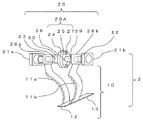
図1は、本発明の第1の実施形態に係る心土破砕機(図5に符号1で示される)の主要部である心土破砕部2の構成を示す。心土破砕部2は、心土破砕装置10と、装置保持部20とを備えている。心土破砕装置10は、心土破砕機の進行中に、土壌中で心土破砕を行う機能を有する。装置保持部20は、心土破砕機において地表上に位置する本体フレームに取り付けられており、心土破砕装置10を上方から支持する機能を有する。なお、心土破砕機は、地表上の本体フレームが牽引機に装着され、牽引機により牽引されることで前方に進行する。
FIG. 1 shows the configuration of a
心土破砕装置10は、土壌中で心土破砕を行う心土破砕刃を有する。好適には、心土破砕刃は、複式接合刃による2本の心土破砕刃11a、11bである。心土破砕刃11a、11bはそれぞれ、上方から下方に延び、力学的性質を考慮した湾曲した波刃を前側に形成されている。
The
心土破砕装置10はさらに、前方かつ下方に少しそり出している土壌差し込み前刃12と、その後方かつ上方に延びる土塊持ち上げ板13とを具備する。土壌差し込み前刃12は、心土破砕刃11a、11bの下端よりも前方に延び、土塊持ち上げ板13は、心土破砕刃11a、11bの下端よりも後方に延びている。
The
2本の心土破砕刃11a、11bは、左右方向に互いに離間して配置されており、好適にはそれらの間の距離が上方が広く下方が狭くなるようにそれぞれ傾斜している。2本の心土破砕刃11a、11bの下端同士は、土壌差し込み前刃12および土塊持ち上げ板13により連結されている。好適には、2本の心土破砕刃11a、11bは、前方から視て逆台形(上辺が下辺より長い台形)の2つの側辺にそれぞれ対応するように配置されている。その場合、土壌差し込み前刃12は、逆台形の下辺に対応するように配置されている。さらに好適には、その逆台形は左右対称である。 The two subsoil crushing blades 11a and 11b are arranged apart from each other in the left-right direction, and are preferably inclined so that the distance between them is wide in the upper direction and narrow in the lower direction. The lower ends of the two subsoil crushing blades 11a and 11b are connected to each other by the soil insertion front blade 12 and the soil mass lifting plate 13. Preferably, the two subsoil crushing blades 11a and 11b are arranged so as to correspond to two side surfaces of an inverted trapezoid (a trapezoid whose upper side is longer than the lower side) when viewed from the front. In that case, the soil insertion front blade 12 is arranged so as to correspond to the lower side of the inverted trapezoid. More preferably, its inverted trapezoid is symmetrical.
装置保持部20は、主要な構成要素として、左右一対の外側フレーム21a、21bと、回転軸29と、左右一対の心土破砕刃保持板28a、28bと、固定側安全板24と、回転側安全板25と、安全ピン27と、接合部材30とを有する。
The
外側フレーム21a、21bは、装置保持部20の左右両端にそれぞれ配置されている。外側フレーム21a、21bは、心土破砕機の本体フレームの一部である破砕機接続フレーム(図5に符号3で示される)と接合される接合面22をそれぞれ有する。図示の例では、接合面22は、前後に向いた各端面である。回転軸29は、図示の例では左右方向に延在する円柱状部材であり、その両端がそれぞれ外側フレーム21a、21bにより回転可能に軸支されている。
The outer frames 21a and 21b are arranged at both left and right ends of the
一方の心土破砕刃保持板28aは、回転軸29の中央と右端との間において回転軸29により貫通されかつ回転軸29に対して不動に固定されている。ここで、「不動に固定」とは、2つの部材が相対的に回転不能であり一体化するように接続されていることを意味する。他方の心土破砕刃保持板28bは、回転軸29の中央と左端との間において回転軸29により貫通されかつ回転軸29に対して不動に固定されている。上述した2本の心土破砕刃11a、11bの各上端は、心土破砕刃保持板28a、28bにそれぞれ不動に固定されている。
One of the subsoil crushing blade holding plates 28a is penetrated by the rotating
固定側安全板24と回転側安全板25は、図示の例では、同じ直径および同じ厚さを有する円盤状の板部材である。固定側安全板24と回転側安全板25は、互いに対向する面同士を当接させて回転軸29上の中央に配置されかつ回転軸29により貫通されている。但し、固定側安全板24は、回転軸29に対して相対的に回転可能であるのに対し、回転側安全板25は、回転軸29に対して不動に固定されている。
The fixed
固定側安全板24および回転側安全板25は、互いに当接した状態で双方を貫通する複数の安全ピン差し込み孔26をそれぞれ穿設されている。心土破砕機の通常の動作中は、固定側安全板24と回転側安全板25とを不動に固定した状態に維持するために、これらの複数の安全ピン差し込み孔26のうち、必要に応じた数の孔にボルト式の安全ピン27が差し込まれ、ナットによりそれぞれ締結されている。図示の例では、4つの安全ピン差し込み孔26が周方向に90度間隔で設けられており、それらのうちの対向する位置にある2つに2本の安全ピン27が差し込まれ締結されている。
The fixed-
さらに、固定側安全板24に対し不動に固定された略円柱状の接合部材30部材が設けられている。接合部材30も回転軸29により貫通されているが回転軸29に対して相対的に回転可能である。接合部材30は、接合面23を形成されており、接合面23は、心土破砕機の本体フレームの一部である破砕機接続フレーム(図5に符号3で示される)と接合される。
Further, a substantially columnar joining
以上の心土破砕部2の構成によれば、心土破砕装置10は、心土破砕刃保持板28a、28bを介して回転軸29に不動に固定されている。また、回転側安全板25も回転軸29に不動に固定されている。すなわち、心土破砕装置10および回転側安全板25は、回転軸29と一体に回転可能である。
According to the above configuration of the
それに対し、固定側安全板24、接合部材30、および外側フレーム21a、21bは、心土破砕機の本体フレームの一部(図5の破砕機接続フレーム3)に不動に固定されており、回転軸29に対しては相対的に回転可能である。
On the other hand, the fixed
但し、固定側安全板24は、回転側安全板25に対し安全ピン27により固定されているので、安全ピン27が破断しない限り、固定側安全板24は回転軸29に対して相対的に回転しない。安全ピン27が保持されている間は、心土破砕装置10と装置保持部20とは全体として不動に固定されている。したがって、少なくとも1つの安全ピン27が取り付けられた状態で行われる通常の動作中、心土破砕装置10および装置保持部20は一体として、心土破砕機の本体フレームと共に前方に進行する。
However, since the fixed
固定側安全板24、回転側安全板25および安全ピン27は、安全装置20Aを構成する。ここで、安全ピン27は所定の破断強度を有しており、所定の剪断力より大きい力が加わると破断する。安全ピン27の数によって所定の剪断力を設定することができる。例えば、心土破砕装置10により土壌中で心土破砕を行っているとき、埋没物に接触/衝突するなどして心土破砕装置10に大きな力が加わると、接合面22、23を介して心土破砕機の本体フレームに力が伝達され、さらに心土破砕機を装着した牽引機にまで力が伝達されて全体に影響が及ぶ。
The fixed-
その場合、所定の剪断力より大きい力が加わることで安全ピン27が破断する。それにより、固定側安全板24と回転側安全板25とが相対的に回転することが可能となる。その結果、加えられた力によって心土破砕装置10が、回転側安全板25および回転軸29と共に、固定側安全板24、接合部材30および外側フレーム21a、21bに対して回転することができる。これにより、心土破砕装置10に加えられた力の影響が大幅に緩和されることになる。その結果、心土破砕機および牽引機の変形損傷を防止することができる。
In that case, the
図2は、図1に示した心土破砕装置10が土壌中を進行する施工状況を模式的に示した斜視図である。進行するとともに、心土破砕刃11a、11bおよび土壌差し込み前刃12により土壌ブロック7を切削して成形し、この土壌ブロック7を土塊持ち上げ板13の傾斜面に沿って持ち上げる。持ち上げによって土壌ブロック7に力を加えることにより、土層の上下を変えることなく土壌ブロック7を圧縮および破砕し、土壌の透水性、通気性および保水性を改善する。さらに、破砕された土壌ブロック7を、土塊持ち上げ板13の傾斜面の後端から心土破砕装置10の後方の、下方に形成された隙間8に落下させる。これにより、透水性等が改善された土壌ブロックの土層を施工前の上下関係のまま戻す。よって、土壌の物理性は改善されるが、化学性を悪化させることなく施工を完了することができる。
FIG. 2 is a perspective view schematically showing a construction situation in which the
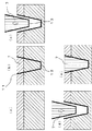
図3(a)〜(e)は、図2に示した施工状況を前方から視た場合の各工程を模式的に示した断面図である。図3(a)に示すように、地表面から下方に向かって配置された2本の心土破砕刃11a、11bと、その下端に前方かつ下方に少しそり出している土壌差し込み前刃12とを有する心土破砕装置10により、断面形状が逆台形の土壌ブロック7を成形する。図3(b)に示すように、この土壌ブロック7を土塊持ち上げ板13の傾斜面に沿って持ち上げることにより力を加えて土壌ブロック7を土層の上下を変えることなく圧縮および破砕し、土壌の透水性、通気性および保水性を改善する。図3(c)に示すように、心土破砕部10の後方に破砕された土壌ブロック7を落下させる。これにより図3(e)に示すように、改善された土壌ブロックの土層を施工前の上下関係のまま戻す。よって、土壌の物理性は改善されるが、化学性を悪化させることなく施工を完了する。
3 (a) to 3 (e) are cross-sectional views schematically showing each process when the construction state shown in FIG. 2 is viewed from the front. As shown in FIG. 3A, two subsoil crushing blades 11a and 11b arranged downward from the ground surface, and a soil insertion front blade 12 slightly protruding forward and downward at the lower end thereof. The
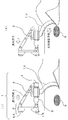
図4(a)(b)は、本発明の第1の実施形態に係る心土破砕部2の安全装置20Aの動作状況を示す。図4(a)は、図2および図3に示した通常の施工を行っているときの状態であり、図1と同じ図である。
4 (a) and 4 (b) show the operating state of the
図4(b)では、心土破砕装置10が土壌中で心土破砕を行っている時に石などの埋没物9に接触または衝突した状態を示す。このとき、心土破砕装置10から装置保持部20を介して心土破砕機の他の部分および牽引機に力が掛かる。その力が、安全装置20Aの安全ピン27の所定の耐力(安全ピン27の配置本数により設定)を超えると、安全ピン27が破断して安全ピン差し込み孔26から外れる。これにより固定側安全板24と回転側安全板25との固定が解除され、固定側安全板24に対して回転側安全板25が相対的に回転可能となる。よって、埋没物9から受ける力により心土破砕装置10、回転軸29および回転側安全板25が回転することによって、心土破砕機の他の部分および牽引機に掛かる力が緩和される。これにより、心土破砕装置10を含む心土破砕機全体並びに牽引機の変形損傷を防止することができる。
FIG. 4B shows a state in which the
図4(a)(b)に示すように、回転側安全板25の側面に位置マークMを付けることが好適である。位置マークMは、例えば、軸方向に引いた直線である。位置マークMが周方向に変位することによって、回転側安全板25が固定側安全板24に対して回転したこと、すなわち安全装置20Aが作動したことを、地表上で視認することができる。
As shown in FIGS. 4A and 4B, it is preferable to attach a position mark M to the side surface of the rotation
図5(a)(b)は、心土破砕機1の全体側面図であり、本発明の第1の実施形態に係る心土破砕部2とその安全装置の作動状況を側面から見た図である。
5 (a) and 5 (b) are overall side views of the
図5(a)に示すように、心土破砕機1は、地表上に位置する本体フレームを備えている。本体フレームは、上述した心土破砕部2が取り付けられる破砕機接続フレーム3と、牽引機(図示せず)に装着するための装着フレーム4と、持ち上げシリンダー5とを有する。装着フレーム4は、例えば、上部装着フレーム4Aと、下部装着フレーム4Bとにより牽引機と連結される。持ち上げシリンダー5は、装着フレーム4と破砕機接続フレーム3との間に接続された油圧シリンダーで構成されており、心土破砕機の姿勢を調整することができる。破砕機接続フレーム3に取り付けられる心土破砕部2は、上述した通り、地表面から下方に向かって配置された心土破砕装置10を有する。
As shown in FIG. 5A, the
図5(b)に示すように、心土破砕装置10に石などの埋没物9が接触/衝突するなどして上述した安全装置が作動すると、心土破砕装置10が後ろ上方に回転して衝撃を回避できることがわかる。
As shown in FIG. 5B, when the above-mentioned safety device is activated by contact / collision of a buried object 9 such as a stone with the
(2)第2の実施形態
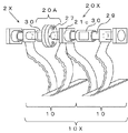
図6は、本発明の第2の実施形態に係る心土破砕機の心土破砕部2Xを概略的に示した斜視図である。心土破砕部2Xは、心土破砕装置10Xと、装置保持部20Xとを有する。心土破砕装置10Xは、図1に示した心土破砕装置10を2連備えており、すなわち4本の心土破砕刃を有する。2つの心土破砕装置10、10は、左右方向に並べられて1本の回転軸29にそれぞれ固定されている。この場合、回転軸29を回転可能に軸支する追加の保持フレーム21cが中央に設けられている。図示の例では、一方の心土破砕装置10の回転軸29上に安全装置20Aが設けられており、他方の心土破砕装置10は、回転軸29上には接合部材30のみが設けられている。図6の心土破砕機によれば、図2および図3に示した土壌ブロック7を同時に2列、隣接して配置できる。
(2) Second Embodiment FIG. 6 is a perspective view schematically showing a soil crushing portion 2X of a soil crusher according to a second embodiment of the present invention. The subsoil crushing unit 2X includes a
(3)第3の実施形態
図7は、本発明の第3の実施形態に係る心土破砕機の心土破砕部2Yを概略的に示した斜視図である。心土破砕部2Yは、心土破砕装置10Yと、装置保持部20Yとを有する。心土破砕装置10Yは、図1に示した心土破砕装置10を3連備えており、すなわち6本の心土破砕刃を有する。3つの心土破砕装置10、10、10は、左右方向に並べられて1本の回転軸29にそれぞれ固定されている。この場合、回転軸29を回転可能に軸支する追加の保持フレーム21c、21dが設けられている。図示の例では、中央の心土破砕装置10の回転軸29上に安全装置20Aが設けられており、左右2つの心土破砕装置10、10は、回転軸29上には接合部材30のみが設けられている。図7の心土破砕機によれば、図2および図3に示した土壌ブロック7を同時に3列、隣接して配置できる。
(3) Third Embodiment FIG. 7 is a perspective view schematically showing a soil crushing portion 2Y of the soil crusher according to the third embodiment of the present invention. The subsoil crushing unit 2Y has a subsoil crushing device 10Y and an apparatus holding unit 20Y. The subsoil crushing device 10Y includes three
なお、心土破砕装置を3連まで連結した心土破砕機を図示し説明したが、3連を上限とする意図ではなく、3連より多い心土破砕装置を連結することも可能である。 Although a subsoil crusher in which up to three subsoil crushers are connected is illustrated and described, it is possible to connect more than three subsoil crushers without the intention of limiting the number to three.
(4)圃場の施工例
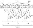
図8は、本発明の第1、第2、第3の実施形態の心土破砕機により施工した圃場の土壌断面図の例を示している。
(4) Example of field construction FIG. 8 shows an example of a soil cross-sectional view of a field constructed by the subsoil crusher of the first, second, and third embodiments of the present invention.
1連式の心土破砕装置10を用いて心土破砕を施工すると、1回の進行において1列の土壌ブロック7を構築できる。土壌ブロック7の深さすなわち改良深Dは、心土破砕刃11a、11bの到達可能深さによって設定される。隣り合う土壌ブロック7同士の間隔W1は、任意に設定できる。
When the subsoil crushing is carried out using the single-series
2連式の心土破砕装置10Xを用いて心土破砕を施工すると、1回の進行において2列の土壌ブロック7を構築できる。隣接する土壌ブロック7同士の間隔(中央間の距離)W2は、2連の心土破砕装置10Xの設計により設定できる。
When the subsoil crushing is performed using the double
3連式の心土破砕装置10Yを用いて心土破砕を施工すると、1回の進行において3列の土壌ブロック7を構築できる。隣接する土壌ブロック7同士の間隔(中央間の距離)W3は、3連の心土破砕装置10Yの設計により設定できる。 When the subsoil crushing is performed using the triple subsoil crushing device 10Y, three rows of soil blocks 7 can be constructed in one progress. The distance (distance between the centers) W3 between the adjacent soil blocks 7 can be set by designing the triple core soil crushing device 10Y.
図8の2連式および3連式の心土破砕装置10X、10Yによる施工で示すように、本発明の心土破砕機によれば、隣接する2つの土壌ブロック7の間に、破砕されていない緊密な土壌6Eが残される。1連式の心土破砕装置10による施工においても、隣り合う列間の距離によって、三角形または台形の断面形状の緊密な土壌6Eが残される。これは、心土破砕装置が、前方から視て逆台形の形状の複式接合刃による2本の心土破砕刃11a、11bを具備することにより実現される。破砕された土壌ブロック7同士の間に緊密な土壌6Eが残されることによって、土壌が全面破砕されることが避けられる。このように、土壌中に硬い部分が残されることで、地表面での機械走行に耐える地耐力を維持でき、また、雨水等の水が土壌中に保持された場合にも全体的に泥沼状態となることを防止できる。
According to the soil crusher of the present invention, it is crushed between two adjacent soil blocks 7 as shown in the construction by the double and triple
加えて、土壌ブロック7の断面形状が逆台形の形状であることから、地表面は広範囲に破砕されることができる。
In addition, since the cross-sectional shape of the
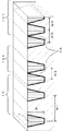
以下に、本発明の実施例を示す。
図9は、図1に示した心土破砕装置10を用いた土壌ブロック7の試験施工の結果を示す土壌中の断面図である。
試験条件は次の通りである。
・試験場所:北海道北見市の台地圃場A
・土壌条件:灰色台地土
・施工速度:2km/h
施工試験の処理区では、心土破砕刃11a、11bと土壌差し込み前刃12の配置形状に対応する逆台形の断面形状で土壌が破砕されている。土壌の硬さの測定方法である山中式土壌硬度計指示値によれば、農作物の生育に不利となる20mm以上の堅密な土層が破砕されて20mm未満の土壌が逆台形の断面形状で構築されていることが見てとれる。これにより、本発明の心土破砕機の実施効果が確認された。
Examples of the present invention are shown below.
FIG. 9 is a cross-sectional view in soil showing the results of test construction of the
The test conditions are as follows.
・ Test site: Plateau field A in Kitami City, Hokkaido
・ Soil condition: Gray plateau soil ・ Construction speed: 2km / h
In the processing section of the construction test, the soil is crushed with an inverted trapezoidal cross-sectional shape corresponding to the arrangement shape of the subsoil crushing blades 11a and 11b and the soil insertion front blade 12. According to the Yamanaka soil hardness tester reading method, which is a method for measuring soil hardness, a dense soil layer of 20 mm or more, which is disadvantageous for the growth of agricultural products, is crushed, and soil of less than 20 mm has an inverted trapezoidal cross-sectional shape. You can see that it is built. As a result, the effect of implementing the subsoil crusher of the present invention was confirmed.
同じ圃場において安全装置の作動を確認するため、下層40cmに40cm角の角石を埋設して、安全装置20Aに安全ピン27を1本設置して、図1に示した心土破砕装置10により施工した。その結果、図4に示すように安全ピン27が破断し、安全装置20Aが作動することを確認した。
なお、試験条件は次の通りである。
・試験場所:北海道北見市の台地圃場A
・土壌条件:灰色台地土
・施工速度:2km/h
・埋没物:40cm角の角石
In order to confirm the operation of the safety device in the same field, a 40 cm square stone was buried in the
The test conditions are as follows.
・ Test site: Plateau field A in Kitami City, Hokkaido
・ Soil condition: Gray plateau soil ・ Construction speed: 2km / h
・ Buried objects: 40 cm square stones
[比較例1]
本発明による心土破砕装置10により施工されなかった、試験圃場における未施工の場所の土壌条件は、以下の通りである。
・試験場所:北海道北見市の台地圃場
・土壌条件:灰色台地土
・土壌硬度:深さ15cm〜50cmの間に山中色度場硬度計指示値が20mm以上の堅密な土層がある。
・作土の亀裂の有無:塊状の土壌構造で、根の伸長がややあるが、透水性がやや低い
・心土の亀裂の有無:壁状の土壌構造で、堅く植物根の伸長は少なく、透水性は低い。特に心土の土壌が密で硬く水の通り道がないため、自然には土壌は改善されない。
[Comparative Example 1]
The soil conditions of the unconstructed place in the test field that were not constructed by the
・ Test site: Plateau field in Kitami City, Hokkaido ・ Soil condition: Gray plateau soil ・ Soil hardness: There is a dense soil layer with a Yamanaka chromaticity field hardness meter reading value of 20 mm or more between depths of 15 cm to 50 cm.
・ Presence or absence of cracks in the soil: Massive soil structure with some root elongation, but slightly low permeability ・ Presence or absence of subsoil cracks: Wall-like soil structure, firm and little root elongation Poor water permeability. In particular, the soil in the heart soil is dense and hard, and there is no water passage, so the soil does not improve naturally.
[比較例2]
本発明による心土破砕装置10により施工されなかった、試験圃場における未施工の場所の土壌条件は、以下の通りである。
・試験場所:北海道北見市の台地圃場
・土壌条件:灰色台地土
・土壌硬度:深さ15cm〜50cmの間に山中色度場硬度計指示値が20mm以上の堅密な土層がある。
・埋没物:なし
[Comparative Example 2]
The soil conditions of the unconstructed place in the test field that were not constructed by the
・ Test site: Plateau field in Kitami City, Hokkaido
-Soil conditions: Gray plateau soil-Soil hardness: There is a dense soil layer with a Yamanaka chromaticity field hardness tester reading value of 20 mm or more between 15 cm and 50 cm in depth.
・ Buried objects: None
以上の通り、本発明による心土破砕装置は、前方から視て逆台形の形状に配置された複式接合刃による2本の心土破砕刃を、好適には1連〜3連備える。これにより、機械走行等のための堅密な土層を下層に適度に残して地耐力を維持しつつ、農業者が所望する機械の使い分けや機械の改良間隔の調整によって透水性、通気性および保水性を改善された土壌ブロックの設置密度を調整できる。断面形状が逆台形の土壌ブロックに破砕されることにより、地表面は広範囲に破砕することができる。 As described above, the subsoil crushing apparatus according to the present invention preferably includes two subsoil crushing blades having a double-joint blade arranged in an inverted trapezoidal shape when viewed from the front. As a result, while maintaining the soil bearing capacity by leaving an appropriate amount of solid soil layer in the lower layer for machine running, etc., water permeability, breathability and breathability can be achieved by properly using the machine desired by the farmer and adjusting the machine improvement interval. The installation density of soil blocks with improved water retention can be adjusted. The ground surface can be crushed over a wide area by being crushed into a soil block having an inverted trapezoidal cross section.
さらに本発明による心土破砕装置は、地下に存在する埋没物に衝突した時、心土破砕装置を支持する装置保持部に設けられた安全装置の安全ピンが破断することによって、心土破砕装置が、心土破砕機の本体フレームに対して回転することができる。これにより、心土破砕装置の心土破砕刃の変形、破損が回避できると共に、心土破砕機における心土破砕装置以外の部分並びにトラクタ等の牽引機の変形、破損も回避できる。この結果、農業者は自分の牽引機を用いて簡単かつ低コストで安全に効果的な心土破砕の施工が可能となる。 Further, the subsoil crushing device according to the present invention is a subsoil crushing device in which a safety pin of a safety device provided in a device holding portion for supporting the subsoil crushing device is broken when it collides with an underground buried object. However, it can rotate with respect to the main frame of the subsoil crusher. As a result, deformation and damage of the soil crushing blade of the soil crushing device can be avoided, and deformation and damage of the part of the soil crusher other than the soil crushing device and the towing machine such as the tractor can be avoided. As a result, farmers will be able to perform simple, low-cost, safe and effective subsoil crushing using their own traction machines.
1 心土破砕機
2 心土破砕部
3 破砕機接続フレーム
4 装着フレーム
4A 上部装着フレーム
4B 下部装着フレーム
5 持ち上げシリンダー
6 土壌
6E 堅密な土壌
7 土壌ブロック
8 隙間
9 埋没物
10 心土破砕装置
10X 2連心土破砕装置
10Y 3連心土破砕装置
11a、11b 心土破砕刃
12 土壌差し込み前刃
13 土塊持ち上げ板
20 装置保持部
21a、21b 外側フレーム
22 接合面
23 接合面
24 固定側安全板
25 回転側安全板
26 安全ピン差し込み孔
27 安全ピン
28a、28b 心土破砕刃保持板
29 回転軸
30 接合部材
M 位置マーク
D 改良深
W 土壌ブロック間隔
1
Claims (6)
前記装置保持部(20)が、
左右方向に延在する回転軸(29)と、
前記回転軸(29)の両端を回転可能に軸支する一対の外側フレーム(21a、21b)と、
前記回転軸(29)上に不動に固定されかつ前記心土破砕装置(10)の前記心土破砕刃の上端が不動に固定される心土破砕刃保持板(28a、28b)と、
互いに対向する面同士を当接させて前記回転軸(29)上に配置された固定側安全板(24)および回転側安全板(25)であって、前記固定側安全板(24)は前記回転軸(29)に対して相対的に回転可能であるのに対し、前記回転側安全板(25)は前記回転軸(29)に対して不動に固定されている、前記固定側安全板(24)および前記回転側安全板(25)と、
前記固定側安全板(24)と前記回転側安全板(25)とを互いに固定するために設けられた1または複数の安全ピン(27)と、
前記固定側安全板(24)に不動に固定されかつ前記心土破砕機(1)の本体フレームと接合される接合部材(30)とを有することを特徴とする心土破砕機。 Soil provided with a soil crushing device (10) having a soil crushing blade for crushing the soil in the soil, and a device holding portion (20) for supporting the soil crushing device (10) from above. In the crusher (1)
The device holding unit (20)
A rotation axis (29) extending in the left-right direction and
A pair of outer frames (21a, 21b) that rotatably support both ends of the rotating shaft (29),
The soil crushing blade holding plates (28a, 28b) which are immovably fixed on the rotating shaft (29) and the upper end of the soil crushing blade of the soil crushing device (10) is immovably fixed.
The fixed side safety plate (24) and the rotating side safety plate (25) are arranged on the rotating shaft (29) by bringing the surfaces facing each other into contact with each other, and the fixed side safety plate (24) is said. The fixed-side safety plate (25) is immovably fixed to the rotating shaft (29) while being rotatable relative to the rotating shaft (29). 24) and the rotating side safety plate (25),
One or more safety pins (27) provided for fixing the fixed side safety plate (24) and the rotating side safety plate (25) to each other, and
A subsoil crusher characterized by having a joining member (30) that is immovably fixed to the fixed side safety plate (24) and is joined to the main body frame of the subsoil crusher (1).
前記心土破砕機(1)を進行させつつ、前記2本の心土破砕刃(11a、11b)および前記土壌差し込み前刃(12)により、断面形状が逆台形の土壌ブロック(7)を成形し、前記土塊持ち上げ板(13)による持ち上げによって前記土壌ブロック(7)を破砕した後、前記土塊持ち上げ板(13)の後端から前記土壌ブロック(7)を下方に落下させることを特徴とする心土破砕方法。 A method for crushing soil using the soil crusher (1) according to claim 5.
While advancing the soil crusher (1), the two soil crushing blades (11a, 11b) and the soil insertion front blade (12) form a soil block (7) having an inverted trapezoidal cross section. Then, after the soil block (7) is crushed by lifting with the soil mass lifting plate (13), the soil block (7) is dropped downward from the rear end of the soil mass lifting plate (13). Subsoil crushing method.
Priority Applications (1)
| Application Number | Priority Date | Filing Date | Title |
|---|---|---|---|
| JP2019089698A JP7017719B2 (en) | 2019-05-10 | 2019-05-10 | Subsoil crusher and subsoil crushing method |
Applications Claiming Priority (1)
| Application Number | Priority Date | Filing Date | Title |
|---|---|---|---|
| JP2019089698A JP7017719B2 (en) | 2019-05-10 | 2019-05-10 | Subsoil crusher and subsoil crushing method |
Publications (2)
| Publication Number | Publication Date |
|---|---|
| JP2020184891A true JP2020184891A (en) | 2020-11-19 |
| JP7017719B2 JP7017719B2 (en) | 2022-02-09 |
Family
ID=73220585
Family Applications (1)
| Application Number | Title | Priority Date | Filing Date |
|---|---|---|---|
| JP2019089698A Active JP7017719B2 (en) | 2019-05-10 | 2019-05-10 | Subsoil crusher and subsoil crushing method |
Country Status (1)
| Country | Link |
|---|---|
| JP (1) | JP7017719B2 (en) |
Cited By (2)
| Publication number | Priority date | Publication date | Assignee | Title |
|---|---|---|---|---|
| CN113519225A (en) * | 2021-08-01 | 2021-10-22 | 张丽 | Gardens are with soil treatment equipment of recycling of earth cultivated in a pot |
| JP2025109059A (en) * | 2024-01-11 | 2025-07-24 | 国立研究開発法人農業・食品産業技術総合研究機構 | Tank-mounted liquid fertilizer application device |
Citations (8)
| Publication number | Priority date | Publication date | Assignee | Title |
|---|---|---|---|---|
| US4895211A (en) * | 1987-11-02 | 1990-01-23 | Harris Edwin D | Land clearing root plow and soil aerator |
| US5695012A (en) * | 1996-08-27 | 1997-12-09 | Technical And Craft Services, Inc. | Adjustable subsoiler with staged shanks |
| JP2008148580A (en) * | 2006-12-14 | 2008-07-03 | Fuji Trailer Manufacturing Co Ltd | Culvert forming device |
| JP2009268439A (en) * | 2008-05-09 | 2009-11-19 | Akutsu Yoshito | Deep tilling device for seeding machine |
| JP2010193776A (en) * | 2009-02-25 | 2010-09-09 | National Agriculture & Food Research Organization | Intertillage weeder |
| JP2010281204A (en) * | 2010-09-24 | 2010-12-16 | National Agriculture & Food Research Organization | Bullet culvert formation method |
| JP2015010369A (en) * | 2013-06-28 | 2015-01-19 | 独立行政法人農業・食品産業技術総合研究機構 | Drilled-hole forming working machine and drilled-hole forming method |
| JP2016052260A (en) * | 2014-09-03 | 2016-04-14 | 国立研究開発法人農業・食品産業技術総合研究機構 | Material burial machine and its construction method |
-
2019
- 2019-05-10 JP JP2019089698A patent/JP7017719B2/en active Active
Patent Citations (8)
| Publication number | Priority date | Publication date | Assignee | Title |
|---|---|---|---|---|
| US4895211A (en) * | 1987-11-02 | 1990-01-23 | Harris Edwin D | Land clearing root plow and soil aerator |
| US5695012A (en) * | 1996-08-27 | 1997-12-09 | Technical And Craft Services, Inc. | Adjustable subsoiler with staged shanks |
| JP2008148580A (en) * | 2006-12-14 | 2008-07-03 | Fuji Trailer Manufacturing Co Ltd | Culvert forming device |
| JP2009268439A (en) * | 2008-05-09 | 2009-11-19 | Akutsu Yoshito | Deep tilling device for seeding machine |
| JP2010193776A (en) * | 2009-02-25 | 2010-09-09 | National Agriculture & Food Research Organization | Intertillage weeder |
| JP2010281204A (en) * | 2010-09-24 | 2010-12-16 | National Agriculture & Food Research Organization | Bullet culvert formation method |
| JP2015010369A (en) * | 2013-06-28 | 2015-01-19 | 独立行政法人農業・食品産業技術総合研究機構 | Drilled-hole forming working machine and drilled-hole forming method |
| JP2016052260A (en) * | 2014-09-03 | 2016-04-14 | 国立研究開発法人農業・食品産業技術総合研究機構 | Material burial machine and its construction method |
Cited By (4)
| Publication number | Priority date | Publication date | Assignee | Title |
|---|---|---|---|---|
| CN113519225A (en) * | 2021-08-01 | 2021-10-22 | 张丽 | Gardens are with soil treatment equipment of recycling of earth cultivated in a pot |
| CN113519225B (en) * | 2021-08-01 | 2023-09-01 | 长春慧华企业管理咨询有限公司 | Gardens are with earth recycle soil treatment facility cultivated in a pot |
| JP2025109059A (en) * | 2024-01-11 | 2025-07-24 | 国立研究開発法人農業・食品産業技術総合研究機構 | Tank-mounted liquid fertilizer application device |
| JP7840583B2 (en) | 2024-01-11 | 2026-04-06 | 国立研究開発法人農業・食品産業技術総合研究機構 | Tank-mounted liquid fertilizer application device |
Also Published As
| Publication number | Publication date |
|---|---|
| JP7017719B2 (en) | 2022-02-09 |
Similar Documents
| Publication | Publication Date | Title |
|---|---|---|
| CN203340580U (en) | Potato harvester | |
| CN105393654A (en) | Vibration deep subsoiler | |
| JP7017719B2 (en) | Subsoil crusher and subsoil crushing method | |
| CN112492898B (en) | High-compactness grassland soil-root system composite soil layer improvement tool and method | |
| CN108353550A (en) | A kind of anti-blocking subsoiler suitable for no-tillage farming | |
| JP5918088B2 (en) | Roller device for crushing soil | |
| CN205040177U (en) | Move stationary knife straw and smash stubble -cleaning rotary cultivator | |
| CN103081590B (en) | Associating subsoiler | |
| CN115280921B (en) | Straw smashing, rotary tillage and mixed burying integrated machine | |
| CN116368973A (en) | Driven and driven root cutting and seam scarifier and its method | |
| KR20110024023A (en) | Bulb crop harvester | |
| US2323460A (en) | Rotary subsoiler | |
| JP2007068528A (en) | Tilling work machine | |
| CN215011420U (en) | A kind of mechanized de-irrigation and rotary tillage work head for hills and mountains | |
| RU2160524C1 (en) | Method and machine for extracting of offset weed rootstocks, preferably licorice roots and rootstocks | |
| CN113141795B (en) | Mechanized rotary tillage working head for removing irrigation in hilly and mountain areas and working method thereof | |
| JPH0436104A (en) | Process for improving tilled subsoil with charged rice chafe and working machine therefor | |
| JP4053063B2 (en) | Soil improvement machine | |
| CN103749008A (en) | Vertical type rotary cultivator special for ditching | |
| CN205830265U (en) | A kind of tiller for paddy field ploughing and weeding | |
| CN209914435U (en) | Rotary-harrow plough and fertilizer application integrated machine | |
| CN220402302U (en) | A kind of straw mulching deep loosening vertical tillage land preparation machine | |
| US2613585A (en) | Rotary subsoiler | |
| JP2007151469A (en) | Subsoil-furrowed soil layer-improving implement | |
| CA2237001C (en) | Frozen top soil cutter |
Legal Events
| Date | Code | Title | Description |
|---|---|---|---|
| A621 | Written request for application examination |
Free format text: JAPANESE INTERMEDIATE CODE: A621 Effective date: 20210105 |
|
| A977 | Report on retrieval |
Free format text: JAPANESE INTERMEDIATE CODE: A971007 Effective date: 20211124 |
|
| TRDD | Decision of grant or rejection written | ||
| A01 | Written decision to grant a patent or to grant a registration (utility model) |
Free format text: JAPANESE INTERMEDIATE CODE: A01 Effective date: 20211216 |
|
| A61 | First payment of annual fees (during grant procedure) |
Free format text: JAPANESE INTERMEDIATE CODE: A61 Effective date: 20220114 |
|
| R150 | Certificate of patent or registration of utility model |
Ref document number: 7017719 Country of ref document: JP Free format text: JAPANESE INTERMEDIATE CODE: R150 |
|
| R250 | Receipt of annual fees |
Free format text: JAPANESE INTERMEDIATE CODE: R250 |
|
| R250 | Receipt of annual fees |
Free format text: JAPANESE INTERMEDIATE CODE: R250 |