JP2020184876A - Wirelessly powered electrochromic window - Google Patents
Wirelessly powered electrochromic window Download PDFInfo
- Publication number
- JP2020184876A JP2020184876A JP2020109176A JP2020109176A JP2020184876A JP 2020184876 A JP2020184876 A JP 2020184876A JP 2020109176 A JP2020109176 A JP 2020109176A JP 2020109176 A JP2020109176 A JP 2020109176A JP 2020184876 A JP2020184876 A JP 2020184876A
- Authority
- JP
- Japan
- Prior art keywords
- power
- window
- power transmission
- wireless power
- electrochromic
- Prior art date
- Legal status (The legal status is an assumption and is not a legal conclusion. Google has not performed a legal analysis and makes no representation as to the accuracy of the status listed.)
- Pending
Links
Images


Classifications
-
- H—ELECTRICITY
- H02—GENERATION; CONVERSION OR DISTRIBUTION OF ELECTRIC POWER
- H02J—ELECTRIC POWER NETWORKS; CIRCUIT ARRANGEMENTS OR SYSTEMS FOR SUPPLYING OR DISTRIBUTING ELECTRIC POWER; SYSTEMS FOR STORING ELECTRIC ENERGY
- H02J50/00—Circuit arrangements or systems for wireless supply or distribution of electric power
- H02J50/10—Circuit arrangements or systems for wireless supply or distribution of electric power using inductive coupling
-
- E—FIXED CONSTRUCTIONS
- E06—DOORS, WINDOWS, SHUTTERS, OR ROLLER BLINDS IN GENERAL; LADDERS
- E06B—FIXED OR MOVABLE CLOSURES FOR OPENINGS IN BUILDINGS, VEHICLES, FENCES OR LIKE ENCLOSURES IN GENERAL, e.g. DOORS, WINDOWS, BLINDS, GATES
- E06B9/00—Screening or protective devices for wall or similar openings, with or without operating or securing mechanisms; Closures of similar construction
- E06B9/24—Screens or other constructions affording protection against light, especially against sunshine; Similar screens for privacy or appearance; Slat blinds
-
- G—PHYSICS
- G02—OPTICS
- G02F—OPTICAL DEVICES OR ARRANGEMENTS FOR THE CONTROL OF LIGHT BY MODIFICATION OF THE OPTICAL PROPERTIES OF THE MEDIA OF THE ELEMENTS INVOLVED THEREIN; NON-LINEAR OPTICS; FREQUENCY-CHANGING OF LIGHT; OPTICAL LOGIC ELEMENTS; OPTICAL ANALOGUE/DIGITAL CONVERTERS
- G02F1/00—Devices or arrangements for the control of the intensity, colour, phase, polarisation or direction of light arriving from an independent light source, e.g. switching, gating or modulating; Non-linear optics
- G02F1/01—Devices or arrangements for the control of the intensity, colour, phase, polarisation or direction of light arriving from an independent light source, e.g. switching, gating or modulating; Non-linear optics for the control of the intensity, phase, polarisation or colour
- G02F1/15—Devices or arrangements for the control of the intensity, colour, phase, polarisation or direction of light arriving from an independent light source, e.g. switching, gating or modulating; Non-linear optics for the control of the intensity, phase, polarisation or colour based on an electrochromic effect
- G02F1/153—Constructional details
-
- G—PHYSICS
- G02—OPTICS
- G02F—OPTICAL DEVICES OR ARRANGEMENTS FOR THE CONTROL OF LIGHT BY MODIFICATION OF THE OPTICAL PROPERTIES OF THE MEDIA OF THE ELEMENTS INVOLVED THEREIN; NON-LINEAR OPTICS; FREQUENCY-CHANGING OF LIGHT; OPTICAL LOGIC ELEMENTS; OPTICAL ANALOGUE/DIGITAL CONVERTERS
- G02F1/00—Devices or arrangements for the control of the intensity, colour, phase, polarisation or direction of light arriving from an independent light source, e.g. switching, gating or modulating; Non-linear optics
- G02F1/01—Devices or arrangements for the control of the intensity, colour, phase, polarisation or direction of light arriving from an independent light source, e.g. switching, gating or modulating; Non-linear optics for the control of the intensity, phase, polarisation or colour
- G02F1/15—Devices or arrangements for the control of the intensity, colour, phase, polarisation or direction of light arriving from an independent light source, e.g. switching, gating or modulating; Non-linear optics for the control of the intensity, phase, polarisation or colour based on an electrochromic effect
- G02F1/163—Operation of electrochromic cells, e.g. electrodeposition cells; Circuit arrangements therefor
-
- H—ELECTRICITY
- H02—GENERATION; CONVERSION OR DISTRIBUTION OF ELECTRIC POWER
- H02J—ELECTRIC POWER NETWORKS; CIRCUIT ARRANGEMENTS OR SYSTEMS FOR SUPPLYING OR DISTRIBUTING ELECTRIC POWER; SYSTEMS FOR STORING ELECTRIC ENERGY
- H02J50/00—Circuit arrangements or systems for wireless supply or distribution of electric power
- H02J50/10—Circuit arrangements or systems for wireless supply or distribution of electric power using inductive coupling
- H02J50/12—Circuit arrangements or systems for wireless supply or distribution of electric power using inductive coupling of the resonant type
-
- H—ELECTRICITY
- H02—GENERATION; CONVERSION OR DISTRIBUTION OF ELECTRIC POWER
- H02J—ELECTRIC POWER NETWORKS; CIRCUIT ARRANGEMENTS OR SYSTEMS FOR SUPPLYING OR DISTRIBUTING ELECTRIC POWER; SYSTEMS FOR STORING ELECTRIC ENERGY
- H02J50/00—Circuit arrangements or systems for wireless supply or distribution of electric power
- H02J50/20—Circuit arrangements or systems for wireless supply or distribution of electric power using microwaves or radio frequency waves
-
- H—ELECTRICITY
- H02—GENERATION; CONVERSION OR DISTRIBUTION OF ELECTRIC POWER
- H02J—ELECTRIC POWER NETWORKS; CIRCUIT ARRANGEMENTS OR SYSTEMS FOR SUPPLYING OR DISTRIBUTING ELECTRIC POWER; SYSTEMS FOR STORING ELECTRIC ENERGY
- H02J50/00—Circuit arrangements or systems for wireless supply or distribution of electric power
- H02J50/30—Circuit arrangements or systems for wireless supply or distribution of electric power using light, e.g. lasers
-
- H—ELECTRICITY
- H02—GENERATION; CONVERSION OR DISTRIBUTION OF ELECTRIC POWER
- H02J—ELECTRIC POWER NETWORKS; CIRCUIT ARRANGEMENTS OR SYSTEMS FOR SUPPLYING OR DISTRIBUTING ELECTRIC POWER; SYSTEMS FOR STORING ELECTRIC ENERGY
- H02J50/00—Circuit arrangements or systems for wireless supply or distribution of electric power
- H02J50/50—Circuit arrangements or systems for wireless supply or distribution of electric power using additional energy repeaters between transmitting devices and receiving devices
-
- H—ELECTRICITY
- H02—GENERATION; CONVERSION OR DISTRIBUTION OF ELECTRIC POWER
- H02J—ELECTRIC POWER NETWORKS; CIRCUIT ARRANGEMENTS OR SYSTEMS FOR SUPPLYING OR DISTRIBUTING ELECTRIC POWER; SYSTEMS FOR STORING ELECTRIC ENERGY
- H02J7/00—Circuit arrangements for charging or discharging batteries or for supplying loads from batteries
- H02J7/865—Battery or charger load switching, e.g. concurrent charging and load supply
-
- E—FIXED CONSTRUCTIONS
- E06—DOORS, WINDOWS, SHUTTERS, OR ROLLER BLINDS IN GENERAL; LADDERS
- E06B—FIXED OR MOVABLE CLOSURES FOR OPENINGS IN BUILDINGS, VEHICLES, FENCES OR LIKE ENCLOSURES IN GENERAL, e.g. DOORS, WINDOWS, BLINDS, GATES
- E06B9/00—Screening or protective devices for wall or similar openings, with or without operating or securing mechanisms; Closures of similar construction
- E06B9/24—Screens or other constructions affording protection against light, especially against sunshine; Similar screens for privacy or appearance; Slat blinds
- E06B2009/2464—Screens or other constructions affording protection against light, especially against sunshine; Similar screens for privacy or appearance; Slat blinds featuring transparency control by applying voltage, e.g. LCD, electrochromic panels
Landscapes
- Engineering & Computer Science (AREA)
- Physics & Mathematics (AREA)
- Power Engineering (AREA)
- Computer Networks & Wireless Communication (AREA)
- Nonlinear Science (AREA)
- Optics & Photonics (AREA)
- Structural Engineering (AREA)
- General Physics & Mathematics (AREA)
- Architecture (AREA)
- Civil Engineering (AREA)
- Electrochromic Elements, Electrophoresis, Or Variable Reflection Or Absorption Elements (AREA)
- Charge And Discharge Circuits For Batteries Or The Like (AREA)
Abstract
【課題】無線送電によって電力供給されるエレクトロクロミックウィンドウを提供する。【解決手段】ネットワーク214において、電力ノード210は、送電部202からの無線電力を中継するか又は変換して、受電部(ウィンドウ204)に、ウィンドウ204の最終的な要求に対してより適した方式で送電する。電力ノード216は、電力ノード210とは異なる方法で、ウィンドウ218の最終的な要求に対してより適切な方式でウィンドウ218内の受電部に無線電力を中継する。ウィンドウ218は、自身に電力を供給するとともに、配線を介してウィンドウ220にも電力を供給する。ウィンドウ218は、ノード216から無線送電を受電して、ウィンドウ218の受電部が、無線送電をウィンドウ218及ウィンドウ220を動作させるために十分な電力に変換する。【選択図】図2EPROBLEM TO BE SOLVED: To provide an electrochromic window to be powered by wireless power transmission. In a network 214, a power node 210 relays or converts radio power from a power transmitting unit 202 to a power receiving unit (window 204), which is more suitable for the final request of the window 204. Power is transmitted by the method. The power node 216 relays wireless power to the power receiving unit in the window 218 in a manner different from that of the power node 210 in a manner more appropriate for the final request of the window 218. The window 218 supplies power to itself and also supplies power to the window 220 via wiring. Window 218 receives wireless power transmission from node 216, and the power receiving unit of window 218 converts the wireless power transmission into sufficient power to operate window 218 and window 220. [Selection diagram] FIG. 2E
Description
本発明は概して、無線送電技術で結合されるエレクトロクロミック(EC)デバイスに関する。本発明は具体的には、無線送電技術を用いて電力供給されるECウィンドウに関する。 The present invention generally relates to electrochromic (EC) devices coupled with wireless power transmission technology. The present invention specifically relates to an EC window that is powered using wireless power transmission technology.
[関連出願]
本願は、米国仮特許出願第61/289,319号(出願日:2009年12月22日)の恩恵および当該仮出願に基づく優先権を主張する。当該仮出願の内容は全て、参照により本願に組み込まれる。
[Related application]
The present application claims the benefits of US Provisional Patent Application No. 61 / 289,319 (Filing Date: December 22, 2009) and priority under the provisional application. All content of the provisional application is incorporated herein by reference.
エレクトロクロミズムは、電子状態が変化すると、通常は、電圧が変化すると、物質の光学特性が可逆的に電気化学的な原因によって変化する現象である。光学特性とは通常、色、透過率、吸収率および反射率のうち1以上である。公知のEC物質の1つに、例えば、酸化タングステン(WO3)がある。酸化タングステンは、電気化学的還元によって色が透明から青色に変化するカソードEC物質である。エレクトロクロミズムは1960年代に発見されたが、ECデバイスならびにECデバイスを備える装置およびシステムの商品化は完全には始まっていない。 Electrochromism is a phenomenon in which the optical properties of a substance are reversibly changed by an electrochemical cause when the electronic state changes, usually when the voltage changes. The optical property is usually one or more of color, transmittance, absorptance and reflectance. One of the known EC substances is, for example, tungsten oxide (WO3). Tungsten oxide is a cathode EC substance whose color changes from transparent to blue by electrochemical reduction. Although electrochromism was discovered in the 1960s, the commercialization of EC devices and devices and systems equipped with EC devices has not begun completely.
エレクトロクロミック物質は、例えば、窓に含められるとしてよい。従来のECウィンドウの欠点の1つに、利用する電力が、量は少ないものの、建物の電源までの有線接続が必要である点が挙げられる。これによって、建設業者が、例えば、大量の窓をオフィス向け建築物に設置する場合に問題が生じる。窓に必要な有線接続に対応しなければならないために、建設に際しては現代構造物を建築するために必要な膨大な品目のリストがあるにも関わらず、さらに課題を増やすことになってしまう。また、ECウィンドウは、現代建築物の高熱ゾーンの管理に関して素晴らしい解決策となるが、例えば、自動熱および/エネルギー管理システムによって制御される場合、有線接続された電源が必要となるECウィンドウは、自動エネルギー管理システムへの統合が難しくなる。このため、有線接続に関する設置コストおよび危険性の上昇によって、新しい建築物でのECウィンドウの採用の動きは鈍く、改修の場合には新しく設置するECウィンドウのために配線設備も設置しなければならなくなるので、改修の際に利用されないことが多い。 The electrochromic material may be included, for example, in the window. One of the drawbacks of conventional EC windows is that although the amount of power used is small, a wired connection to the power supply of the building is required. This creates problems for builders, for example, when installing large numbers of windows in office buildings. The need to accommodate the wired connections required for windows adds to the challenge of construction, despite the vast list of items needed to build modern structures. EC windows are also a great solution for managing high thermal zones in modern buildings, but EC windows that require a wired power supply, for example when controlled by an automatic heat and / energy management system, Difficult to integrate into automated energy management systems. For this reason, the adoption of EC windows in new buildings has slowed down due to the increase in installation costs and risks associated with wired connections, and in the case of renovation, wiring equipment must also be installed for the newly installed EC windows. Since it disappears, it is often not used for renovation.
無線送電技術によって電力供給を受けるエレクトロクロミックデバイス、特に、ECウィンドウを説明する。本発明の一の側面は、欠陥が少なく高信頼性のECウィンドウであって、無線送電が可能なECウィンドウである。 Electrochromic devices powered by wireless power transmission technology, especially EC windows, will be described. One aspect of the present invention is a highly reliable EC window with few defects and capable of wireless power transmission.
無線で電力供給されるECウィンドウを実現するべく無線送電技術を組み込んだスケーラブルECウィンドウ技術を説明する。このような技術は任意で、環境センサ、無線制御、および/または、一部の側面では、光起電力を含むとしてよい。本発明によれば、ECウィンドウ技術の全ての利点を生かすことが可能となり、国家レベルで年間に数百トンもの炭素および大量のエネルギーを節約することが可能となる。新しい建築物は無線電力供給ECウィンドウの恩恵を大いに享受し、窓の交換のために配線設置が問題となっていた改修については特に利点が大きい。 A scalable EC window technology incorporating wireless power transmission technology to realize an EC window that is powered wirelessly will be described. Such techniques may optionally include photovoltaics, environmental sensors, wireless control, and / or, in some aspects, photovoltaics. According to the present invention, it is possible to take advantage of all the advantages of EC window technology, and to save hundreds of tons of carbon and a large amount of energy per year at the national level. New buildings will greatly benefit from wireless power supply EC windows, especially for refurbishment where wiring installation has been a problem for window replacement.
一実施形態は、無線送電によって電力供給されるECデバイスである。一実施形態によると、ECデバイスはECウィンドウである。無線送電技術を用いて、ECウィンドウの1以上のECデバイスに電力を供給する。無線電力は、ウィンドウ内のECデバイスに直接電力供給するために用いられるとしてもよいし、または、別の実施形態によると、ウィンドウ内のECデバイスのEC遷移および/またはEC状態に電力を供給する内部電池を充電するために用いられるとしてもよい。一実施形態によると、無線送電は、複数のECウィンドウに電力供給する受電部によって受電される。無線電力はさらに、ECウィンドウの一部またはECウィンドウを直接サポートしている他の能動素子、例えば、動きセンサ、光センサ、熱センサ、湿度センサ、無線通信センサ等に電力供給するためにも用いられ得る。無線通信技術はさらに、無線で電力供給されるECウィンドウを制御するためにも用いられ得る。 One embodiment is an EC device powered by wireless power transmission. According to one embodiment, the EC device is an EC window. Wireless power transmission technology is used to power one or more EC devices in the EC window. The wireless power may be used to power the EC device in the window directly, or, according to another embodiment, power the EC transition and / or EC state of the EC device in the window. It may be used to charge the internal battery. According to one embodiment, the wireless power transmission is received by a power receiving unit that supplies power to a plurality of EC windows. Wireless power is also used to power parts of the EC window or other active elements that directly support the EC window, such as motion sensors, optical sensors, thermal sensors, humidity sensors, wireless communication sensors, etc. Can be. Wireless communication technology can also be used to control wirelessly powered EC windows.
ECウィンドウと組み合わせて用いるには、任意の適切な種類の無線送電技術を利用するとしてよい。無線送電技術には、例えば、これらに限定されるものではないが、誘導、共振誘導、無線周波数送電、マイクロ波送電、および、レーザ送電がある。一実施形態によると、無線周波数を用いて受電部に電力を送電し、当該受電部が、偏波、例えば、円偏波、楕円偏波および/または二重偏波、および/または、さまざまな周波数およびベクトルを利用してこの電力を電流に変換する。別の実施形態によると、磁界の誘導結合を利用して電力を無線で送電する。具体的な実施形態によると、有線接続されている外部電源から電力を受け取る第1の共振器(流れる電気エネルギー、例えば、ACを磁界に変換するコイル)、および、第2の共振器(第1の共振器が生成した磁界に結合されているので、誘導により電気エネルギーを生成するコイル)を用いて電力を無線で送電する。第2の共振器は、第1の共振器および第2の共振器の磁界共振結合によって電流または電位を生成することによって、受電部として機能する。磁気誘導を利用する実施形態は必ずしも磁界共振結合を利用する必要はないが、利用する実施形態では、局所化されたエバネセント磁界パターンによる近接場共振が比較的高効率の無線送電方法となる。 For use in combination with the EC window, any suitable type of wireless power transmission technology may be utilized. Radio transmission techniques include, but are not limited to, induction, resonance induction, radio frequency transmission, microwave transmission, and laser transmission, for example. According to one embodiment, the radio frequency is used to transmit power to a powered unit, which may be polarized, such as circularly polarized, elliptically polarized and / or double polarized, and / or various. Convert this power into current using frequencies and vectors. According to another embodiment, power is transmitted wirelessly by utilizing inductive coupling of magnetic fields. According to a specific embodiment, a first resonator (a coil that converts flowing electrical energy, for example, AC into a magnetic field) and a second resonator (first) that receive power from an external power source connected by wire. Since it is coupled to the magnetic field generated by the resonator, power is transmitted wirelessly using a coil that generates electrical energy by induction). The second resonator functions as a power receiving unit by generating a current or an electric potential by the magnetic resonance coupling of the first resonator and the second resonator. The embodiment using magnetic induction does not necessarily use magnetic field resonance coupling, but in the embodiment using magnetic field resonance, near-field resonance due to a localized evanescent magnetic field pattern is a relatively highly efficient wireless power transmission method.
一実施形態によると、ウィンドウの受電部はRFアンテナである。別の実施形態によると、RFアンテナは、RF電力を、ECデバイスを機能させるために用いられる電位に変換する。別の実施形態によると、受電部は、第1の共振器に共振結合されている第2の共振器であり、第1の共振器から第2の共振器に無線で電力が送電されるように構成されている。第2の共振器は、無線で送電された電力をECウィンドウに電力供給するための電気に変換する。 According to one embodiment, the power receiving part of the window is an RF antenna. According to another embodiment, the RF antenna converts RF power into the potential used to make the EC device work. According to another embodiment, the power receiving unit is a second resonator that is resonantly coupled to the first resonator so that power is wirelessly transmitted from the first resonator to the second resonator. It is configured in. The second resonator converts the power transmitted wirelessly into electricity for supplying power to the EC window.
受電部は通常、RFアンテナまたは二次共振コイルのいずれであろうと、ECウィンドウのフレーム内、例えば、IGUの外側封止部の近傍および/またはウィンドウフレーム内のどこかに配されて、IGUのガラスを通して見ることが可能な領域の邪魔にならないようにする。このため、特定の実施形態によると、受電部のサイズは比較的小さい。一実施形態によると、受電部のサイズは、ウィンドウのユーザが受電部がウィンドウの一部であることを認識しない程度に十分に小さいが、受電部はユーザの視界に入らないように隠されている。 The power receiving part, whether it is an RF antenna or a secondary resonant coil, is usually located within the frame of the EC window, for example, near the outer sealing part of the IGU and / or somewhere in the window frame of the IGU. Do not get in the way of the area visible through the glass. Therefore, according to a particular embodiment, the size of the power receiving unit is relatively small. According to one embodiment, the size of the power receiving unit is small enough that the window user does not recognize that the power receiving unit is part of the window, but the power receiving unit is hidden from the user's field of view. There is.
一実施形態によると、無線送電は、特定の領域内のウィンドウの受電部に送電する電力ノードを1以上含む無線送電ネットワークを介して実行される。建築物または必要に応じて、1以上の、場合によっては幾つかのノードを利用して、それぞれ対応するウィンドウの受電部に給電する複数の電力ノードから成る電力ノードネットワークを形成する。一実施形態によると、無線周波数を用いて電力を送電し、複数の電力ノードが存在する場合、これら複数の電力ノードでは複数の周波数および/または偏極ベクトルが用いられていて、さまざまなレベルまたは種類の電力が、さまざまなノードから、さまざまな電力需要を持つウィンドウへと送電されている。磁気誘導を用いて無線送電を行う別の実施形態によると、この実施形態でも1以上の電力ノードが存在するが、この実施形態では、電力ノード自体が共振器である。例えば、一実施形態によると、電源から電力を受電する第1の共振器は、第2の共振器に共振結合されており、第2の共振器は、例えば、ECウィンドウに配電する第3の共振器に共振結合されている。このようにして、第2の共振器は、第1の共振器から、第2の共振器へ、そして第3の共振器へと続く送電ネットワーク内の電力ノードとして機能し、第3の共振器は、受電部として機能し、磁界を電力に変換してECウィンドウに電力を送電する。 According to one embodiment, wireless power transmission is performed via a wireless power transmission network that includes one or more power nodes that transmit to the power receiving section of a window within a particular area. Buildings or, optionally, one or more, and in some cases several nodes, are used to form a power node network consisting of multiple power nodes that power the power receiving parts of their respective windows. According to one embodiment, when power is transmitted using radio frequencies and there are multiple power nodes, these multiple power nodes use multiple frequencies and / or polarization vectors at different levels or. Different types of power are transmitted from different nodes to windows with different power demands. According to another embodiment of wireless power transmission using magnetic induction, there are one or more power nodes in this embodiment as well, but in this embodiment the power nodes themselves are resonators. For example, according to one embodiment, the first resonator that receives power from the power source is resonantly coupled to the second resonator, and the second resonator, for example, distributes power to the EC window. It is resonantly coupled to the resonator. In this way, the second resonator functions as a power node in the transmission network that continues from the first resonator to the second resonator and then to the third resonator, and the third resonator. Functions as a power receiving unit, converts a magnetic field into electric power, and transmits electric power to the EC window.
本発明の別の側面は、ECデバイスに電力供給する方法である。当該方法は、無線電力の生成および/または無線電力の受電部への送電を実行して、当該受電部が当該無線電力を、ECデバイスに電力供給するために用いられる電気エネルギー(例えば、電流または電位)に変換する段階i)と、当該電気エネルギーをECデバイスに配電する段階ii)とを備える。一実施形態によると、ECデバイスは、上述したように、ECウィンドウである。別の実施形態によると、段階i)はRFによって実行され、別の実施形態によると、段階i)は磁気誘導によって実行される。一実施形態によると、受電部から出力される電気エネルギーは、ECウィンドウのECデバイスに電力供給するために用いられる電池を充電するために用いられる。一実施形態によると、一のウィンドウは、一の無線電力受電部を備えており、当該受電部が生成する電気エネルギーは、複数のECウィンドウに電力を供給するために用いられる。この電力供給は、直接行われるとしてもよく、および/または、複数のウィンドウに対応付けられている一の電池または電池群を充電することによって行われるとしてもよい。 Another aspect of the present invention is a method of supplying power to an EC device. The method performs the generation and / or transmission of wireless power to a receiving unit and the electrical energy (eg, current or) used by the receiving unit to power the wireless power to an EC device. It includes a step i) of converting to a potential) and a step ii) of distributing the electric energy to the EC device. According to one embodiment, the EC device is an EC window, as described above. According to another embodiment, step i) is performed by RF and according to another embodiment, step i) is performed by magnetic induction. According to one embodiment, the electrical energy output from the power receiving unit is used to charge the battery used to power the EC device of the EC window. According to one embodiment, one window comprises one wireless power receiving unit, and the electrical energy generated by the power receiving unit is used to supply power to a plurality of EC windows. This power supply may be done directly and / or by charging a single battery or group of batteries associated with a plurality of windows.
本発明の別の側面は、i)無線電力を送電する無線送電部と、ii)無線電力を受電して当該無線電力を中継する電力ノードと、iii)中継された無線電力を受電して、無線電力を電気エネルギーに変換する受電部と、iv)電気エネルギーを受電して、2以上の光学的状態間の遷移を発生させるために、および/または、一の光学的状態を維持するために電力を供給するECデバイスとを備える無線送電ネットワークである。電気エネルギーは、直接的または間接的にECデバイスによって受電され得る。一実施形態によると、電気エネルギーは、受電部から直接受電されて、別の実施形態によると、電気エネルギーは受電部から電池へと流されて、その後でECデバイスに流される。一実施形態によると、ECデバイスは、ECウィンドウの一部である。 Another aspect of the present invention is i) a wireless power transmission unit that transmits wireless power, ii) a power node that receives wireless power and relays the wireless power, and iii) receives relayed wireless power. A power receiving unit that converts wireless power into electrical energy, and iv) to receive electrical energy to generate a transition between two or more optical states and / or to maintain one optical state. It is a wireless transmission network including an EC device that supplies electric power. Electrical energy can be received directly or indirectly by an EC device. According to one embodiment, the electrical energy is received directly from the power receiving unit, and according to another embodiment, the electrical energy is flowed from the power receiving unit to the battery and then to the EC device. According to one embodiment, the EC device is part of an EC window.
特定の実施形態によると、ECデバイスは、電気エネルギーの一部を、上述したように無線電源から受け取り、さらなる電気エネルギーを、任意でECデバイスに(例えば、IGU内またはIGUの近傍、例えば、ウィンドウのフレーム内に)一体化されている太陽光電源から受け取る。このようなシステムでは、ECデバイスに電力供給するための配線、対応するコントローラ、センサ等が必要ないとしてよい。 According to certain embodiments, the EC device receives some of the electrical energy from the wireless power source as described above and optionally further electrical energy to the EC device (eg, in or near the IGU, eg, a window). Receive from the integrated solar power supply (inside the frame). Such a system may not require wiring, corresponding controllers, sensors, etc. to power the EC device.
上記およびその他の特徴および利点は、添付図面を参照しつつ、さらに詳細に後述する。 The above and other features and advantages will be described in more detail below with reference to the accompanying drawings.
以下に記載する詳細な説明は、添付図面を参照することによって、より深く理解されたい。図面は以下の通りである。
本発明では、広義に解釈すると、無線送電源から電力供給されるECデバイスを説明する。より具体的な実施形態では、ECウィンドウは、無線電源から電力供給される。無線送電は、ECウィンドウへの電力供給に特に適している。これは、ECウィンドウが通常、ECデバイスで遷移を発生させる場合、および/または、ECデバイスの光学的状態を維持する場合に数ボルトのオーダという低い電位を用いて機能するためである。ECウィンドウは通常、1日の間に数回遷移が発生するに過ぎない。また、無線送電を利用して、対応する電池を充電して、無線送電を利用して1以上のECウィンドウに間接的に電力供給することもできる。 In a broad sense, the present invention describes an EC device that is powered by a wireless power transmission. In a more specific embodiment, the EC window is powered by a wireless power source. Wireless power transmission is particularly suitable for powering EC windows. This is because EC windows typically function with low potentials on the order of a few volts when causing transitions in the EC device and / or maintaining the optical state of the EC device. EC windows usually have only a few transitions during the day. It is also possible to use wireless power transmission to charge the corresponding battery and use wireless power transmission to indirectly power one or more EC windows.
配線を持つウィンドウを設置する場合、建築家および建設業者にとって考慮すべき事項が増え、改修の場合には、対象となる建築物に以前には設置されていなかった配線設備を追加する必要が出てくるので、配線は特に大きな問題となる。無線送電技術およびECウィンドウという高度な技術を組み合わせることで、上述した問題が解決され、エネルギー節約と共に、ECウィンドウの有線電気接続を一体化するために費やされる時間およびコストが節約されるという相乗効果が得られる。 When installing windows with wiring, there are more considerations for architects and builders, and in the case of renovations, it is necessary to add wiring equipment that was not previously installed in the target building. Wiring is a particularly big problem because it comes. The combination of wireless power transmission technology and advanced technology of EC window solves the above problems, and has the synergistic effect of saving energy and the time and cost spent to integrate the wired electrical connection of EC window. Is obtained.
商用および住居用の窓に利用される、動的でECを利用する断熱ガラスユニット(Insulated Glass Unit(IGU))は、低電圧に応じて光透過特性が変化することによって、窓を通過する光および熱の量を制御することができる。ECデバイスは、低い電位を用いて透明(「透明または無色」)状態と、暗くした(「光および/または熱を遮蔽する」)状態との間で変化し、さらに低い電力で光学的状態を維持することができる。動的でECを利用するウィンドウは、当該ウィンドウを通過する光の量を制御することが可能である。一の側面によると、暗くした状態であっても可視性は持つので、変わらず外部環境を視認することが可能である一方、例えば、暑い天気の場合に熱を発生させる太陽光を遮蔽するか、または、寒い天気の場合には断熱性によって建物内に貴重な熱を保持することによって、エネルギーを節約する。 Dynamic and EC-based insulated glass units (Insulated Glass Units (IGUs)) used for commercial and residential windows have light that passes through the window due to changes in light transmission characteristics in response to low voltage. And the amount of heat can be controlled. EC devices vary between a transparent (“transparent or colorless”) state with a low potential and a darkened (“light and / or heat shield”) state, with even lower power to provide an optical state. Can be maintained. A window that uses EC dynamically can control the amount of light that passes through the window. According to one aspect, it has visibility even in the dark, so it is possible to see the external environment unchanged, but on the other hand, for example, whether to shield the sunlight that generates heat in hot weather. Or, in cold weather, the insulation saves energy by retaining valuable heat inside the building.
このような動的なウィンドウの一例を挙げると、欠陥が少なく高信頼性のECウィンドウであって、固体のEC積層材料を含むECウィンドウがある。このように全体が固体且つ無機の材料で構成されているECデバイス、当該ECデバイスを製造する方法、および、欠陥の基準については、米国特許出願第12/645,111号(発明の名称:「欠陥の少ないエレクトロクロミックデバイスの製造(Fabrication of Low−Defectivity Electrochromic Devices)」、出願日:2009年12月22日、発明者:マーク・コズロウスキ(Mark Kozlowski)他)、米国特許出願第12/645,159号(発明の名称:「エレクトロクロミックデバイス(Electrochromic Devices)」、出願日:2009年12月22日、発明者:ゾンチュン・ワン(Zhongchun Wang)他))、米国特許出願第12/772,055号および第12/772,075号(出願日:2010年4月30日))、米国特許出願第12/814,277号及び第12/814,279号、出願日:2010年6月11日)(最後の4つの出願の発明の名称は、「エレクトロクロミックデバイス(Electrochromic Devices)」、発明者はゾンチュン・ワン(Zhongchun Wang)他)により詳細に記載されている。上記6つの特許出願はそれぞれ、参照により本願に組み込まれる。本発明の一の側面は、例えば、これらに限定されないが、上記の6件の米国特許出願のうちいずれか1つに記載されているECウィンドウ等のECウィンドウに、無線送電技術によって電力供給するというものである。当該ECウィンドウは、受電部によって電気エネルギーを変換した後、無線送電技術を利用して直接電力供給されるとしてよい。および/または、電気エネルギーは、ウィンドウに電力供給するためにも利用される電池を充電するために用いられるとしてもよい。 An example of such a dynamic window is an EC window that has few defects and is highly reliable and contains a solid EC laminated material. Regarding the EC device which is entirely composed of a solid and inorganic material, the method for manufacturing the EC device, and the criteria for defects, US Patent Application No. 12 / 645,111 (title of invention: " Fabrication of Low-Defective Devices, filing date: December 22, 2009, inventor: Mark Kozlowski et al., US Patent Application No. 12/645 No. 159 (Title of the invention: "Electrochromic Devices", filing date: December 22, 2009, inventor: Zhongchun Wang et al.), US Patent Application No. 12 / 772,055 Nos. and 12 / 772,075 (Filing Date: April 30, 2010), US Patent Applications Nos. 12 / 814,277 and 12 / 814,279, Filing Date: June 11, 2010 ) (The titles of the inventions in the last four patents are described in detail by "Electrochromic Devices", the inventor is Zhongchun Wang et al.). Each of the above six patent applications is incorporated herein by reference. One aspect of the present invention is, for example, supplying power to an EC window such as, but not limited to, the EC window described in any one of the above six US patent applications by wireless power transmission technology. That is. The EC window may be directly supplied with electric power by using wireless power transmission technology after converting electric energy by a power receiving unit. And / or electrical energy may be used to charge a battery that is also used to power the window.
無線送電は、電気エネルギーが電源から電気負荷へと相互接続配線無しで送電される場合のプロセスである。広義では、電流は、大気中、水中または固体物等の環境を、配線を必要とすることなく、通過することができる。しかし、より有用性の高い(制御された)方式の無線送電技術が存在し、例えば、RF、磁気誘導、レーザまたはマイクロ波エネルギーを介して送電する。無線送電は、瞬間的または継続的なエネルギー伝達が必要となるが、相互接続配線があると不便、問題が多い、危険性が高い、または、不可能な場合に特に有用性が高い。無線送電は、電気力学誘導等の誘導を利用したものであるとしてよく、または、無線周波数(RF)、マイクロ波およびレーザ等の他の公知のエネルギー伝達媒体に基づいて行われるとしてよい。 Wireless transmission is the process by which electrical energy is transmitted from a power source to an electrical load without interconnect wiring. In a broad sense, electric current can pass through environments such as air, water or solids without the need for wiring. However, there are more useful (controlled) methods of wireless power transmission, such as power transmission via RF, magnetic induction, laser or microwave energy. Wireless transmission requires instantaneous or continuous energy transfer, but is particularly useful when interconnected wiring is inconvenient, problematic, dangerous, or impossible. Radio transmission may utilize induction such as electrodynamic induction, or may be based on other known energy transfer media such as radio frequency (RF), microwaves and lasers.
一部の実施形態によると、RFを介して電力を送電して、ECデバイス、特に、ECウィンドウと電気的に接続されている受電部で、この電力を電位または電流に変換するとしてよい。RFを利用した送電方法で特に有用性の高いものが、米国特許出願公開公報第2007/0191074号(米国特許出願第11/699,148号、出願日:2007年1月29日、発明の名称:「送電ネットワークおよび送電方法」、ダニエル・ダブリュー・ハリスト(Daniel W. Harrist)他)に記載されている。当該特許文献は、参照により本願に組み込まれる。 According to some embodiments, power may be transmitted via RF to convert this power into an electric potential or current at an EC device, particularly a power receiving unit that is electrically connected to an EC window. A particularly useful power transmission method using RF is US Patent Application Publication No. 2007/0191074 (US Patent Application No. 11 / 699,148, filing date: January 29, 2007, title of invention). : "Transmission Network and Transmission Method", Daniel W. Harrist et al.). The patent document is incorporated herein by reference.
他の実施形態では、外部電源から電力供給される第1の共振器、および、第1の共振が発生させる磁界エネルギーを、ECウィンドウのECデバイスに供給する電力に変換する第2の共振器を利用して、磁気誘導によって送電を行う。磁気誘導を利用した送電方法で特に有用性の高い方法が、米国特許出願公開公報第2007/0222542号(米国特許出願第11/481,077号、出願日:2006年7月5日、発明の名称:「非放射方式の無線エネルギー伝達」、ジョン・ジョアンナプロス(John Joannapoulos)他)に記載されている。当該特許文献は、参照により本願に組み込まれる。誘導によって無線方式で電力を制御する方法として有用性の高い別の方法は、米国特許第7,382,636号(出願日:2005年10月14日、発明の名称:「負荷に電力供給するシステムおよび方法」、デイビッド・バーマン(David Baarman)他に記載されている。当該特許文献は、参照により本願に組み込まれる。本明細書で説明するECウィンドウは、このような無線送電制御方法を利用可能である。 In another embodiment, a first resonator powered by an external power source and a second resonator that converts the magnetic field energy generated by the first resonance into power supplied to the EC device of the EC window. It is used to transmit power by magnetic induction. A particularly useful method of power transmission using magnetic induction is U.S. Patent Application Publication No. 2007/0222542 (US Patent Application No. 11 / 481,077, filing date: July 5, 2006, invention). Name: "Non-radiative radio energy transmission", John Joannapoulos et al.). The patent document is incorporated herein by reference. Another method that is highly useful as a method of wirelessly controlling electric power by induction is US Pat. No. 7,382,636 (Filing date: October 14, 2005, title of invention: "Powering a load". Systems and Methods ”, David Baarman et al., Which patent documents are incorporated herein by reference. The EC windows described herein utilize such wireless power transmission control methods. It is possible.
特定の実施形態は、複数の無線送電源を備える。すなわち、本発明は、一の無線送電源が利用される実施形態に限定されない。例えば、無線送電ネットワークが利用される実施形態では、一の無線送電方法、例えば、RF送電方法を、当該ネットワークの一部で利用しつつ、他の方法、例えば、磁気誘導方式を当該ネットワークの別の一部で利用する。 Certain embodiments include a plurality of wireless transmissions. That is, the present invention is not limited to the embodiment in which one wireless power transmission power source is used. For example, in an embodiment in which a wireless power transmission network is used, one wireless power transmission method, for example, an RF power transmission method, is used in a part of the network, while another method, for example, a magnetic induction method is used in another method of the network. It is used in a part of.
本発明の一の側面は、無線送電源から電力供給されるECウィンドウである。一実施形態によると、ECウィンドウのサイズは利用できればどのようなサイズであってもよく、例えば、自動車で用いられる場合、例えば、サンルーフまたはバックミラーで用いられる場合、配線は、車両のフロントガラスを横断する等、不便である。一実施形態によると、ECウィンドウは、当該ウィンドウのECデバイスの基板として、建築用基準のガラスを利用する。建築用ガラスは、建設資材として利用されるガラスである。建築用ガラスは通常、商用の建築物で利用されるが、住居用の建築物でも利用され得ると共に、通常では、必要ではないが、室内環境と屋外環境を分離するために用いられる。建築用ガラスは、少なくとも20インチ×20インチであり、約80インチ×80インチまで大きくすることができる。一部の実施形態によると、ECデバイスは全て、固体且つ無機の材料で形成される。ウィンドウは、例えば、ウィンドウ構造の一部として、RF受電部または共振器等の受電部を備える。 One aspect of the present invention is an EC window powered by a wireless power transmission. According to one embodiment, the size of the EC window can be any size available, for example when used in a car, for example in a sunroof or rearview mirror, the wiring will be on the windshield of the vehicle. It is inconvenient to cross. According to one embodiment, the EC window utilizes building standard glass as the substrate for the EC device of the window. Architectural glass is glass used as a construction material. Architectural glass is typically used in commercial buildings, but can also be used in residential buildings, and is usually not necessary, but used to separate indoor and outdoor environments. Architectural glass is at least 20 inches x 20 inches and can be as large as about 80 inches x 80 inches. According to some embodiments, all EC devices are made of solid and inorganic materials. The window includes, for example, a power receiving unit such as an RF power receiving unit or a resonator as a part of the window structure.
図1は、ECウィンドウの製造プロセス100を示す図である。同図に示すウィンドウ構造は、無線送電を受電して、電力を電気エネルギーに変換し、ウィンドウのECデバイスに当該電気エネルギーを直接的または間接的に供給する受電部135を備えている。直接的または間接的な電力供給は、例えば、ECデバイスに直接電力供給するか、または、ECウィンドウに電力供給するために用いられる電池を充電するかである。ECパネル105は、ECデバイス(不図示だが、例えば、表面A)およびECデバイスに電力供給するバスバー110を有しており、別のガラスパネル115と整合させる。IGU125の製造時、セパレータ120は、基板105と基板115との間に挟持され、両基板と合わせられる。IGU125は、セパレータ120に接する基板の面およびセパレータ120の内周面によって画定される内部空間を持つ。セパレータ120は通常、封止セパレータである。つまり、スペーサを有しており、当該スペーサと各基板との間に封止剤を有し、ここにおいて内部領域を気密封止するべく接しているので、湿気等から内部を保護する。通常は、ガラスパネルがセパレータに封着されると、二次封止剤をIGUのセパレータ120の外周端縁の周囲に塗布して、外囲環境からさらに保護するべく封止するだけでなく、IGUの構造強度をさらに高めるとしてよい。IGUは、フレームによって支持されており、ウィンドウ構造130を構成している。ウィンドウフレームを一部切り欠いて、本例では、アンテナを含む無線受電部135を露出して表示している。受電部135は、IGUに近接しており、この例では、ウィンドウ構造130のフレーム内に配されている。無線送電受電部は、ウィンドウコントローラの構成要素であってよい。
FIG. 1 is a diagram showing a
一実施形態によると、無線送電源は、無線周波数を用いて送電する。このような実施形態に係るECウィンドウは、無線周波数受電部を有しており、無線周波数受電部は、無線周波数を、ECウィンドウ内のECデバイスに電力供給するために用いられる電気エネルギー(例えば、電流または電位)に変換する。ECデバイスへの電力供給は、ECデバイスの光学的状態の維持または光学的状態の遷移を発生させるための電力供給のうち少なくとも1つを含む。一実施形態によると、無線周波数受電部は、ECウィンドウのIGUの内部または近傍に配されている。例えば、受電部は、IGUを支持するウィンドウフレーム内に配されているとしてもよいし、IGUのガラスパネル間を分離しているスペーサの近傍の領域に配されているとしてもよいし、その両方であってもよい。例えば図1に示すように、受電部はIGUの可視領域の邪魔にならないことが好ましいが必須ではない。 According to one embodiment, the wireless power transmission uses a wireless frequency to transmit electricity. The EC window according to such an embodiment has a radio frequency power receiving unit, and the radio frequency power receiving unit uses electrical energy (for example, for example) to supply electric power to an EC device in the EC window. Convert to current or potential). The power supply to the EC device includes at least one of the power supplies for maintaining the optical state of the EC device or causing the transition of the optical state. According to one embodiment, the radio frequency power receiving unit is arranged inside or near the IGU of the EC window. For example, the power receiving unit may be arranged in the window frame supporting the IGU, may be arranged in the region near the spacer separating the glass panels of the IGU, or both. It may be. For example, as shown in FIG. 1, it is preferable that the power receiving unit does not interfere with the visible region of the IGU, but it is not essential.
別の実施形態によると、磁界の誘導結合によって無線送電を行う。一般的には、一次コイル(当該コイルを流れる電気エネルギー、例えば、ACを磁界に変換する)が、電源から電力供給を受けて磁界を生成し、二次コイルが磁界に結合されることによって誘導により電気エネルギーを生成する。二次コイルが生成した電気エネルギーは、ECデバイス、具体的な実施形態では、ECウィンドウのECデバイスに電力供給するために利用される。共振結合された磁気エネルギーを利用する具体的な実施形態によると、有線接続されている外部電源から電力を受電する第1の共振器、および、第2の共振器を用いて無線送電を実行する。第2の共振器は、第1の共振器および第2の共振器の磁界共振結合を用いて電流を生成することによって、受電部として機能する。磁気誘導を利用する実施形態は必ずしも磁界共振結合を利用する必要はないが、利用する実施形態では、局所化されたエバネセント磁界パターンによる近接場共振が比較的高効率の無線送電方法となる。 According to another embodiment, wireless power transmission is performed by inductive coupling of magnetic fields. In general, a primary coil (which converts electrical energy flowing through the coil, eg, AC, into a magnetic field) receives power from a power source to generate a magnetic field, which is induced by coupling the secondary coil to the magnetic field. Generates electrical energy. The electrical energy generated by the secondary coil is used to power the EC device, specifically the EC device of the EC window. According to a specific embodiment using resonantly coupled magnetic energy, wireless power transmission is performed using a first resonator that receives power from an external power source connected by wire and a second resonator. .. The second resonator functions as a power receiving unit by generating an electric current using the magnetic resonance coupling of the first resonator and the second resonator. The embodiment using magnetic induction does not necessarily use magnetic field resonance coupling, but in the embodiment using magnetic field resonance, near-field resonance due to a localized evanescent magnetic field pattern is a relatively highly efficient wireless power transmission method.
一実施形態によると、受電部は、RFアンテナまたは共振コイルのいずれであろうと、ECウィンドウのIGUの近傍、例えば、IGUの封止部またはウィンドウフレームの近傍に配されて、IGUのガラスを通して見ることが可能な領域の邪魔にならないようにする。このため、特定の実施形態によると、受電部のサイズは比較的小さい。「サイズが小さい」とは、例えば、ECウィンドウの可視領域の約5%以下を受電部が占めることを意味する。一実施形態によると、受電部は、ECウィンドウのうち可視領域にかかることはない。つまり、受電部は、サイズが十分に小さいので、ウィンドウのユーザは受電部がウィンドウの一部であることに気付かず、受電部はユーザの視界には入らない。例えば、ウィンドウのフレーム内に収納される。一実施形態によると、受電部がIGUの封止領域に収納されている場合、ウィンドウのフレームは、受電部への経路を確保できるように1以上のアクセスポートを含むか、または、受電部はウィンドウフレーム内に恒久的に封止されるとしてよい。また、無線送電に影響を与えないポートおよび/または物質が存在するとしてよい。このため、受電部は、ウィンドウフレームを形成する物質との間で干渉を発生させることなく無線送電を適切に受電することができる。 According to one embodiment, the powered section, be it an RF antenna or a resonant coil, is located near the IGU of the EC window, eg, near the IGU enclosure or window frame and viewed through the glass of the IGU. Do not get in the way of possible areas. Therefore, according to a particular embodiment, the size of the power receiving unit is relatively small. “Small size” means, for example, that the power receiving unit occupies about 5% or less of the visible region of the EC window. According to one embodiment, the power receiving unit does not cover the visible region of the EC window. That is, the power receiving unit is small enough that the window user is unaware that the power receiving unit is part of the window and the power receiving unit is out of the user's field of view. For example, it is housed in the frame of the window. According to one embodiment, when the powered unit is housed in the sealing area of the IGU, the frame of the window may include one or more access ports to provide a path to the powered unit, or the powered unit may. It may be permanently sealed within the window frame. Also, there may be ports and / or substances that do not affect wireless power transmission. Therefore, the power receiving unit can appropriately receive wireless power transmission without causing interference with the substance forming the window frame.
具体的な実施形態によると、ECデバイスに印加される電位を調整するコントローラ、例えば、マイクロプロセッサが設けられている。当該コントローラは任意で、ウィンドウを機能させるために用いられる電池の再充電、ウィンドウコントローラと無線通信する自動熱および/またはエネルギー管理システム、ハンドヘルドデバイス等の遠隔制御部との無線通信等の他の機能を(単独で、または、他のマイクロプロセッサと共に)制御するとしてよい。 According to a specific embodiment, a controller for adjusting the electric potential applied to the EC device, for example, a microprocessor is provided. The controller may optionally have other functions such as recharging the battery used to make the window function, an automatic heat and / or energy management system that wirelessly communicates with the window controller, wireless communication with remote controls such as handheld devices. May be controlled (alone or with other microprocessors).
一実施形態によると、無線送電は、特定領域におけるウィンドウ受電部に送電する電力ノードを1以上備えるネットワークを用いて実行される。本明細書で説明する無線送電ネットワークは、必要に応じて、RF、磁気誘導またはこれらの両方を利用するとしてよい。建築物によっては、1以上、時にはいくつかのノードを利用して、対応するウィンドウ受電部に給電する電力ノードを複数備える電力ノードネットワークを形成する。無線周波数を用いて送電し、複数の電力ノードがある一実施形態によると、電力ノードが用いる周波数および/または偏極ベクトルは複数あるので、さまざまなレベルまたは種類の電力が、さまざまなノードから、さまざまな電力需要を持つウィンドウへと送電される。 According to one embodiment, wireless power transmission is performed using a network having one or more power nodes to transmit power to a window power receiving unit in a specific area. The wireless power transmission network described herein may utilize RF, magnetic induction, or both, as appropriate. Depending on the building, one or more, and sometimes several nodes, are used to form a power node network having a plurality of power nodes that supply power to the corresponding window power receiving units. According to one embodiment of transmitting using a radio frequency and having multiple power nodes, there are multiple frequencies and / or polarization vectors used by the power nodes, so that different levels or types of power can be transmitted from different nodes. It is transmitted to windows with various power demands.
磁気誘導を用いて無線送電を行う一実施形態によると、この実施形態でも1以上の電力ノードが存在するが、電力ノード自体が共振器である。例えば、一実施形態によると、電源から電力を受電する第1の共振器は、第2の共振器に共振結合されており、第2の共振器は、例えば、ECウィンドウに電力を配電する第3の共振器に共振結合されている。このようにして、第2の共振器は、第1の共振器から、第2の共振器へ、そして第3の共振器へと続く送電ネットワーク内の電力ノードとして機能し、第3の共振器は、受電部として機能して、磁界を電力に変換することによってECウィンドウに電力を送電する。このようにすることで、近接場の磁気エネルギーは長距離にわたり、特定の建築物のECウィンドウの需要が満たされる。 According to one embodiment of wireless power transmission using magnetic induction, there are one or more power nodes in this embodiment as well, but the power nodes themselves are resonators. For example, according to one embodiment, the first resonator that receives power from the power source is resonantly coupled to the second resonator, and the second resonator distributes power to, for example, the EC window. It is resonantly coupled to the resonator of 3. In this way, the second resonator functions as a power node in the transmission network that continues from the first resonator to the second resonator and then to the third resonator, and the third resonator. Functions as a power receiving unit to transmit power to the EC window by converting the magnetic field into power. By doing so, the magnetic energy in the near field extends over a long distance to meet the demand for EC windows in a particular building.
別の実施形態は、ECデバイスに電力供給する方法であって、i)無線電力を生成する段階と、ii)無線電力を、無線電力をECデバイスに電力供給するために用いられる電気エネルギーに変換する受電部に送電する段階と、iii)電気エネルギー(例えば、電流または電位)を、ECデバイスおよび/またはECデバイスに電力供給するために用いられる電池に配電する段階とを備える方法である。一実施形態によると、ECデバイスはECウィンドウである。他の実施形態によると、無線電力の生成は、無線周波数を用いて送電を行う無線送電部を用いて実行され、電気エネルギーは電圧である。別の実施形態によると、無線電力の生成は、磁気誘導、より具体的な実施形態によると、共振結合された磁気誘導を用いて送電を行う無線送電部を用いて実行される。他の具体的な実施形態によると、上記の段階ii)および段階iii)は、上述した無線送電ネットワークのうち少なくとも1つを用いて実行される。上述した実施形態のうち一の具体的な実施形態によると、ECデバイスは、ECウィンドウのECパネルの一部である。さらに具体的な実施形態によると、ECパネルは、建築用ガラス規模のものである。別の実施形態によると、段階i)、段階ii)および段階iii)のうち少なくとも1つは無線通信を用いて実行される。一実施形態は、受電部によって、ECデバイスに電力供給するために用いられる電池を充電するべく、無線送電を変換することによって生成される電気エネルギーを利用することを含む。 Another embodiment is a method of supplying power to an EC device, i) generating wireless power and ii) converting the wireless power into electrical energy used to power the EC device. It is a method including a step of transmitting power to a power receiving unit and a step of distributing iii) electric energy (for example, current or potential) to an EC device and / or a battery used for supplying power to the EC device. According to one embodiment, the EC device is an EC window. According to another embodiment, the generation of radio power is performed using a radio transmission unit that transmits power using radio frequencies, and the electrical energy is voltage. According to another embodiment, the generation of wireless power is performed using a wireless power transmission unit that transmits power using magnetic induction, or more specifically, resonantly coupled magnetic induction. According to other specific embodiments, the steps ii) and iii) above are performed using at least one of the wireless transmission networks described above. According to one specific embodiment of the embodiments described above, the EC device is part of the EC panel of the EC window. According to a more specific embodiment, the EC panel is of architectural glass scale. According to another embodiment, at least one of step i), step ii) and step iii) is performed using wireless communication. One embodiment comprises utilizing the electrical energy generated by converting wireless power transmission to charge a battery used to power an EC device by a power receiving unit.
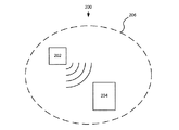
図2Aは、無線送電ネットワーク200を示す概略図である。無線送電ネットワークは、本明細書で説明するように、例えば、RF電力または磁気誘導を用いて、無線電力をECウィンドウ204に送電する無線送電部202を備える。本発明は、ECウィンドウに限定されることはなく、無線送電によって電力供給されるECデバイスであれば本発明の範囲に含まれる。エレクトロクロミックウィンドウ204は、無線送電された電力を、ECウィンドウ内のECデバイスおよび/またはウィンドウコントローラ、センサ等を動作させるために用いられる電気エネルギーへと変換する受電部を備える。一実施形態によると、電気エネルギーは、ECデバイスの光学的状態の遷移および/または維持のために供給される電力として利用される電圧である。ECデバイスは通常、入力に応じてECデバイスを制御および管理するマイクロプロセッサ等のコントローラが対応付けられている。さらに、ECデバイスは、ネットワークを介してECデバイスと通信する外部コントローラによって制御および管理され得る。入力は、直接的または無線通信を介してユーザによって手動で入力されるとしてよい。または、入力は、ECウィンドウが一部を成している建築物の自動熱および/またはエネルギー管理システムからの入力であってもよい。
FIG. 2A is a schematic view showing a wireless
無線送電ネットワークは通常、領域206によって画定されている。つまり、送電は通常、領域206に局所化されているが、必ずしもそうではない。領域206は、1以上のウィンドウが配されており、無線電力が送電される領域を画定しているとしてよい。送電部202は、一部の実施形態では領域206の外部にある(そして、当該領域内に送電する)としてよい。または、図2Aに示すように領域206内にあるとしてもよい。一実施形態によると、無線受電部は、ECウィンドウのIGUに近接して配されている。受電部は、ECウィンドウを通して見える視界の邪魔にならないことが好ましい。当業者であれば、上記のような無線電力ネットワークは複数のECウィンドウを含み、これら複数のECウィンドウへは1以上の送電部によって無線で電力が供給されるものと認められたい。また、無線電力によって生成される電気エネルギーは、ECウィンドウにおける電池または太陽光発電の電源を増強するために用いられ得る。一実施形態によると、太陽光発電の電源は、無線送電によって実行される電池の充電を増強するために用いられる。
The wireless transmission network is usually defined by
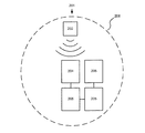
図2Bは、別の無線送電ネットワーク201を示す概略図である。ネットワーク201は、送電部202から送電される無線電力が、ECウィンドウ204内の受電部で受電されて、ウィンドウ204だけでなくウィンドウ205に対しても電力供給するために用いられる点を除き、図2Aを参照して上述したネットワーク200と略同様である。つまり、一のウィンドウの受電部が、無線送電を電気エネルギーに変換して、複数のECウィンドウに対して、直接的に、または、受電部が充電する1以上の電池によって電力供給する。この例では、ウィンドウ204に対応付けられている受電部が無線送電を電気エネルギーに変換して、配線を介して電気エネルギーをウィンドウ205に送電している。これには、ウィンドウ毎に受電部を設置する必要がなく、ある程度の配線は用いられるものの、建築物全体に配線を設置する必要がなく、配線がウィンドウ設置領域に局所的に集中するので、ウィンドウ同士が電気的に接続されるという利点がある。また、ECウィンドウは電力需要が高くないので、この構成は実用性が高い。
FIG. 2B is a schematic diagram showing another wireless
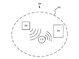
図2Cは、別の無線送電ネットワーク208を示す概略図である。ネットワーク208は、送電部202から送電される無線電力はECウィンドウ204内の受電部によって直接受電されるのではなく電力ノード210を介して中継される点を除いて、図2Aを参照しつつ上述したネットワーク200と略同様である。電力ノード210は、受電と同一の方式(例えば、RFアンテナまたは誘導コイルを用いて受電)で電力を中継するとしてもよいし、無線電力を変換して、ウィンドウ204の(最終的な)要求に対してより適切な方式で受電部に送電するとしてもよい。一例を挙げると、電力ノードは、ある方式、例えば、RF誘導または磁気誘導で無線送電を受電して、上記の方式のうち別のいずれかの方式で無線電力をウィンドウ204へ送電する。一実施形態は、電力ノードである。当該電力ノードは、1以上の方式で無線送電を受電して、当該送電を電気エネルギーに変換する無線送電受電部と、電気エネルギーを上記の1以上の方式の無線送電に変換する無線送電部とを備える。一実施形態によると、無線送電部は、電気エネルギーを、無線受電部の受電と同じ方式の無線送電に変換する。方式は同じであるが、例えば、利用している周波数または極性が異なり、電力ノードの受電部は、送電部202からの無線送電と、電力ノード210の送電部からの無線送電とを識別することができる。一実施形態によると、無線送電部は、電気エネルギーを、無線受電部が受電する方式以外の方式の無線送電に変換する。
FIG. 2C is a schematic diagram showing another wireless
図2Dは、別の無線送電ネットワーク212を示す概略図である。ネットワーク212は、送電部202から送電される無線電力が電力ノード210を介して複数のウィンドウ204に中継される点を除いて、図2Cを参照しつつ上述したネットワーク208と略同様である。繰り返しになるが、電力ノード210は、受電と同一の方式で電力を中継することも可能であるし(例えば、RFアンテナまたは誘導コイルで受電)、または、無線電力を変換して、ウィンドウ204の(最終的な)要求に対してより適切な方式で受電部に送電するとしてもよい。この例では、送電部202は、領域206の外部に配されている。この例では、複数のウィンドウ204の電力要求は同じになっているが、本発明はこれに限定されない。つまり、ノード210から送電される無線電力は、さまざまな電力需要を持つ複数のECウィンドウの電力要求を満足させるのに十分なレベルであるとしてよい。さまざまな電力需要を持つとは、例えば、電力ノード210からの無線送電を電気エネルギーに適宜変換する構成要素が、各ウィンドウ204の受電部の一部である場合である。
FIG. 2D is a schematic diagram showing another wireless
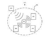
一実施形態によると、一の無線送電ネットワーク内の複数のウィンドウの電力要求が異なる場合、電力需要が異なるウィンドウについて複数の異なる電力ノードを利用する。各ノードから中継される電力は、例えば、電力レベルが異なるとしてもよいし、および/または、送電方法が異なるとしてもよい。図2Eは、このような無線送電ネットワーク214を示す概略図である。ネットワーク214は、送電部202から送電される無線電力が2つの電力ノード210および216を介して中継される点を除き、図2Dを参照しつつ上述したネットワーク212と略同様である。電力ノード210は、受電と同一の方式で電力を中継するとしてもよいし(例えば、RFアンテナまたは誘導コイルを介して受電)、または、無線電力を変換して、受電部(ウィンドウ204)に、ウィンドウ204の(最終的な)要求に対してより適した方式で送電するとしてもよい。電力ノード216は、電力ノード210とは異なる方法で無線電力を中継する。つまり、電力ノード216は、無線電力を変更して、ウィンドウ218の(最終的な)要求に対してより適切な方式でウィンドウ218内の受電部に送電する。この例では、ウィンドウ218は、自身に電力を供給するとともに、配線を介してウィンドウ220にも電力を供給する。ウィンドウ218は、ノード216から無線送電を受電して、ウィンドウ218の受電部は、無線送電を、ウィンドウ218およびウィンドウ220を動作させるために十分な電力に変換する。このため、本明細書で説明する実施形態は、複数の異なる電力ノードが、例えば、一の送電部から同じ方式で無線エネルギーを受電するが、ECデバイス毎に(対応する受電部を介して)方式を変更して無線エネルギーを中継するとしてよい。この例では、ECウィンドウ毎に、電力要求が異なる。この例では、送電部202は、領域206の外部に配されている。具体的な実施形態によると、一の無線送電部が無線電力を送電し、複数のECウィンドウがそれぞれ、無線電力を、当該ウィンドウに固有の需要に適切な電気エネルギーに変換するように構成されている受電部を有する。別の実施形態によると、各ウィンドウが有する受電部は、無線電力を同じ電気エネルギーに変換するように同じ受電部であるが、この電気エネルギーが、当該受電部に接続されている1以上の電子素子、例えば、整流器、電圧変換器、周波数変換器、変圧器、またはインバータによって、当該ウィンドウに固有の需要に合わせて変換される。
According to one embodiment, if the power requirements of a plurality of windows in one wireless transmission network are different, a plurality of different power nodes are utilized for windows having different power demands. The power relayed from each node may have different power levels and / or different transmission methods, for example. FIG. 2E is a schematic view showing such a wireless
一実施形態は、無線送電ネットワークである。当該無線送電ネットワークは、i)無線電力を送電する無線送電部と、ii)無線電力を受電して、当該無線電力を中継する電力ノードと、iii)中継された無線電力を受電して、無線電力を電気エネルギーに変換する受電部と、iv)電気エネルギーを受電するECデバイスとを備える。一実施形態によると、ECデバイスはECウィンドウである。別の実施形態によると、電力ノードはRFアンテナを有する。一実施形態によると、電力ノードは誘導コイルを有する。別の実施形態によると、受電部は、RF受電部である。別の実施形態によると、受電部は、誘導コイルである。他の実施形態によると、電力ノードは、無線電力をECウィンドウに中継する前に、ECウィンドウの要求に応じて、無線電力を変換する。一部の実施形態によると、無線電力ネットワークは、複数の電力ノードを備えている。各電力ノードは、1以上のECウィンドウに電力を中継する。各電力ノードは、それぞれが対応する受電部を備える複数のECウィンドウの要求に応じて無線電力を中継する。 One embodiment is a wireless power transmission network. The wireless power transmission network has i) a wireless power transmission unit that transmits wireless power, ii) a power node that receives wireless power and relays the wireless power, and iii) receives relayed wireless power and wirelessly. It includes a power receiving unit that converts electric power into electric energy, and iv) an EC device that receives electric energy. According to one embodiment, the EC device is an EC window. According to another embodiment, the power node has an RF antenna. According to one embodiment, the power node has an induction coil. According to another embodiment, the power receiving unit is an RF power receiving unit. According to another embodiment, the power receiving unit is an induction coil. According to another embodiment, the power node converts the radio power at the request of the EC window before relaying the radio power to the EC window. According to some embodiments, the wireless power network comprises a plurality of power nodes. Each power node relays power to one or more EC windows. Each power node relays wireless power in response to a request from a plurality of EC windows, each of which has a corresponding power receiving unit.
上述した本発明は理解し易くなるようにある程度詳細に説明してきたが、説明した実施形態は一例に過ぎず本発明を制限するものではない。特許請求の範囲において変更および変形が可能であることは当業者には明らかであろう。
[項目1]
無線送電源によって電力供給されるエレクトロクロミックウィンドウ。
[項目2]
前記無線送電源は、無線周波数または磁気誘導を利用して送電する項目1に記載のエレクトロクロミックウィンドウ。
[項目3]
前記無線送電源からの無線送電を前記エレクトロクロミックウィンドウ内のエレクトロクロミックデバイスに電力供給するために用いられる電気エネルギーに変換する受電部を備える項目2に記載のエレクトロクロミックウィンドウ。
[項目4]
前記電気エネルギーは、前記エレクトロクロミックデバイスに電力供給するために用いられる電池を充電するために利用される項目3に記載のエレクトロクロミックウィンドウ。
[項目5]
前記エレクトロクロミックデバイスは、固体且つ無機の材料で構成される項目3に記載のエレクトロクロミックウィンドウ。
[項目6]
前記無線送電源は、送電ネットワークを用いて送電する項目2に記載のエレクトロクロミックウィンドウ。
[項目7]
前記送電ネットワークは、前記無線送電源から送電される電力を前記エレクトロクロミックウィンドウに中継する電力ノードを含む項目6に記載のエレクトロクロミックウィンドウ。
[項目8]
前記エレクトロクロミックウィンドウの機能は、無線通信を用いて制御される項目7に記載のエレクトロクロミックウィンドウ。
[項目9]
エレクトロクロミックデバイスに電力供給する方法であって、
i)無線送電を生成する段階と、
ii)前記無線送電を、前記無線送電を前記エレクトロクロミックデバイスに電力供給するために用いられる電気エネルギーに変換する受電部に送電する段階と、
iii)前記電気エネルギーを、前記エレクトロクロミックデバイスおよび/または前記エレクトロクロミックデバイスに電力供給するために用いられる電池に配電する段階とを備える方法。
[項目10]
前記エレクトロクロミックデバイスは、エレクトロクロミックウィンドウの一部である項目9に記載の方法。
[項目11]
前記無線送電を生成する段階は、RFまたは磁気誘導を利用する無線送電部を用いて実行される項目10に記載の方法。
[項目12]
前記エレクトロクロミックウィンドウは、前記エレクトロクロミックウィンドウのIGUに近接して配されている無線受電部を含む項目11に記載の方法。
[項目13]
前記無線送電部は、無線送電ネットワークを用いて、前記受電部に前記無線送電を送電する項目12に記載の方法。
[項目14]
前記無線送電ネットワークは、前記無線送電部からの前記無線送電を前記受電部に中継する電力ノードを含む項目13に記載の方法。
[項目15]
前記エレクトロクロミックウィンドウの機能は、無線通信を用いて制御される項目10に記載の方法。
[項目16]
無線送電ネットワークであって、
i)無線電力を送電する無線送電部と、
ii)前記無線電力を受電して前記無線電力を中継する電力ノードと、
iii)中継された前記無線電力を受電して前記無線電力を電気エネルギーに変換する受電部と、
iv)前記電気エネルギーを受電するエレクトロクロミックデバイスと
を備える無線送電ネットワーク。
[項目17]
前記エレクトロクロミックデバイスは、エレクトロクロミックウィンドウの一部である項目16に記載の無線送電ネットワーク。
[項目18]
無線電力は、RFまたは磁気誘導を用いて送電される項目17に記載の無線送電ネットワーク。
[項目19]
前記電力ノードは、前記エレクトロクロミックウィンドウの要求に応じて、前記無線電力を前記エレクトロクロミックウィンドウに中継する前に、前記無線電力を変換し、
前記無線電力の変換は、前記無線電力を、電気エネルギー、異なる方式の無線電力、異なる周波数の無線電力、および、異なる極性の無線電力のうち少なくとも1つを変更することを含む項目18に記載の無線送電ネットワーク。
[項目20]
複数の電力ノードをさらに備え、
前記複数の電力ノードはそれぞれ、前記無線電力を1以上の別のエレクトロクロミックウィンドウに中継し、
前記複数の電力ノードはそれぞれ、前記1以上の別のエレクトロクロミックウィンドウの要求に応じて前記無線電力を中継し、
前記1以上の別のエレクトロクロミックウィンドウは、前記複数の電力ノードのそれぞれに対応して受電部を持つ項目19に記載の無線送電ネットワーク。
Although the present invention described above has been described in some detail for ease of understanding, the described embodiments are merely examples and do not limit the present invention. It will be apparent to those skilled in the art that modifications and modifications can be made within the scope of the claims.
[Item 1]
An electrochromic window powered by wireless power.
[Item 2]
The electrochromic window according to item 1, wherein the wireless power transmission is transmitted by using a wireless frequency or magnetic induction.
[Item 3]
The electrochromic window according to item 2, further comprising a power receiving unit that converts wireless power transmission from the wireless power transmission source into electrical energy used to supply power to an electrochromic device in the electrochromic window.
[Item 4]
The electrochromic window according to item 3, wherein the electrical energy is used to charge a battery used to power the electrochromic device.
[Item 5]
The electrochromic window according to item 3, wherein the electrochromic device is made of a solid and inorganic material.
[Item 6]
The electrochromic window according to item 2, wherein the wireless power transmission is transmitted using a power transmission network.
[Item 7]
The electrochromic window according to item 6, wherein the power transmission network includes a power node that relays power transmitted from the wireless power transmission to the electrochromic window.
[Item 8]
The electrochromic window according to item 7, wherein the function of the electrochromic window is controlled by using wireless communication.
[Item 9]
A way to power an electrochromic device
i) The stage of generating wireless power transmission and
ii) A step of transmitting the wireless power transmission to a power receiving unit that converts the wireless power transmission into electric energy used for supplying power to the electrochromic device.
iii) A method comprising the steps of distributing the electrical energy to the electrochromic device and / or a battery used to power the electrochromic device.
[Item 10]
9. The method of item 9, wherein the electrochromic device is part of an electrochromic window.
[Item 11]
The method of item 10, wherein the step of generating the wireless power transmission is performed using a wireless power transmission unit that utilizes RF or magnetic induction.
[Item 12]
The method according to item 11, wherein the electrochromic window includes a wireless power receiving unit arranged in the vicinity of the IGU of the electrochromic window.
[Item 13]
The method according to item 12, wherein the wireless power transmission unit transmits the wireless power transmission to the power receiving unit using a wireless power transmission network.
[Item 14]
The method according to item 13, wherein the wireless power transmission network includes a power node that relays the wireless power transmission from the wireless power transmission unit to the power receiving unit.
[Item 15]
The method according to item 10, wherein the function of the electrochromic window is controlled by using wireless communication.
[Item 16]
It ’s a wireless power transmission network.
i) A wireless power transmission unit that transmits wireless power,
ii) A power node that receives the wireless power and relays the wireless power,
iii) A power receiving unit that receives the relayed wireless power and converts the wireless power into electrical energy.
iv) A wireless power transmission network including an electrochromic device that receives the electric energy.
[Item 17]
The wireless power transmission network according to item 16, wherein the electrochromic device is a part of an electrochromic window.
[Item 18]
The wireless power transmission network according to item 17, wherein the wireless power is transmitted using RF or magnetic induction.
[Item 19]
At the request of the electrochromic window, the power node converts the radio power before relaying the radio power to the electrochromic window.
The conversion of the radio power according to item 18, wherein the conversion of the radio power includes changing the radio power to at least one of electric energy, a radio power of a different method, a radio power of a different frequency, and a radio power of a different polarity. Wireless power transmission network.
[Item 20]
With multiple power nodes
Each of the plurality of power nodes relays the radio power to one or more different electrochromic windows.
Each of the plurality of power nodes relays the radio power in response to the request of the one or more different electrochromic windows.
The wireless power transmission network according to item 19, wherein the one or more separate electrochromic windows have power receiving units corresponding to each of the plurality of power nodes.
Claims (33)
前記エレクトロクロミックウィンドウに対する電力を生成するよう構成された太陽光発電の電源と、を備え、
前記エレクトロクロミックデバイスは、ウィンドウコントローラによって無線通信を用いて無色状態と暗くした状態との間で変化するように制御されるよう構成され、
前記ウィンドウコントローラは、ネットワークを介して前記エレクトロクロミックデバイスと通信する
システム。 An electrochromic window with an electrochromic device and
With a photovoltaic power source configured to generate power for the electrochromic window,
The electrochromic device is configured to be controlled by a window controller to change between a colorless state and a darkened state using wireless communication.
The window controller is a system that communicates with the electrochromic device via a network.
請求項1に記載のシステム。 The system of claim 1, further comprising a battery configured to distribute power to the electrochromic device.
請求項2に記載のシステム。 The system according to claim 2, wherein the power source for photovoltaic power generation is configured to charge the battery.
請求項3に記載のシステム。 The system of claim 3, wherein the window controller is further configured to control charging of the battery.
請求項1から4のいずれか一項に記載のシステム。 The system according to any one of claims 1 to 4, wherein the electrochromic window is in the form of a heat insulating glass unit.
請求項5に記載のシステム。 The system according to claim 5, wherein the power source for the photovoltaic power generation is in or near the heat insulating glass unit.
請求項1から5のいずれか一項に記載のシステム。 The system according to any one of claims 1 to 5, wherein the power source for the photovoltaic power generation is in the electrochromic window.
請求項1から7のいずれか一項に記載のシステム。 The system according to any one of claims 1 to 7, further comprising a power receiving unit configured to convert wireless power transmission received from a wireless power transmission into electrical energy.
前記太陽光発電の電源および前記無線送電源の両方が前記電池に電力を配電するよう構成される
請求項8に記載のシステム。 Further equipped with a battery configured to distribute power to the electrochromic device.
The system according to claim 8, wherein both the photovoltaic power source and the wireless power transmission source are configured to distribute electric power to the battery.
請求項8または9に記載のシステム。 The system according to claim 8 or 9, wherein the system does not have external wiring for supplying power to the system.
請求項8から10のいずれか一項に記載のシステム。 The system according to any one of claims 8 to 10, wherein the wireless power transmission is transmitted by using magnetic induction, radio frequency, microwave energy, or a laser.
請求項1から11のいずれか一項に記載のシステム。 The system according to any one of claims 1 to 11, further comprising one or more sensors.
請求項12に記載のシステム。 The system according to claim 12, wherein the one or more sensors include one or more of a motion sensor, an optical sensor, a thermal sensor, and a humidity sensor.
請求項1から13のいずれか一項に記載のシステム。 The system according to any one of claims 1 to 13, wherein the electrochromic device has a solid and inorganic laminated material arranged on a glass substrate.
請求項8に記載のシステム。 The system according to claim 8, wherein the wireless power transmission is transmitted by using a power transmission network.
請求項1から15のいずれか一項に記載のシステム。 The system according to any one of claims 1 to 15, wherein the electrochromic window is a component of an automatic heat and / or energy management system for a building.
請求項8に記載のシステム。 The system according to claim 8, wherein the window controller has a wireless power transmission / reception unit.
請求項1から17のいずれか一項に記載のシステム。 The system according to any one of claims 1 to 17, wherein the window controller comprises a microprocessor configured to adjust the potential applied to the electrochromic device.
請求項18に記載のシステム。 18. The system of claim 18, wherein the microprocessor controls battery recharging or wireless communication with a remote control unit, either alone or in combination with other microprocessors.
請求項19に記載のシステム。 19. The system of claim 19, wherein the remote control unit is a handheld device or an automatic heat and / or energy management system.
請求項1から20のいずれか一項に記載のシステム。 The system according to any one of claims 1 to 20, wherein the window controller controls the electrochromic device in response to an input received via wireless communication.
請求項21に記載のシステム。 The system according to claim 21, wherein the input is from an automatic energy management system for buildings.
請求項22に記載のシステム。 The system according to claim 22, wherein the electrochromic window is a component of the automatic energy management system.
太陽光発電の電源を用いて、前記エレクトロクロミックウィンドウに対する電力を生成する段階と、
エレクトロクロミックデバイスにおいて無色状態と暗くした状態との間で光学的状態の遷移を、ウィンドウコントローラからの無線通信を介して制御する段階であって、前記ウィンドウコントローラは、ネットワークを介して前記エレクトロクロミックデバイスと通信する、段階とを備える
方法。 A method of supplying power to an electrochromic window.
The stage of generating electric power for the electrochromic window using a photovoltaic power source, and
The stage of controlling the transition of the optical state between the colorless state and the darkened state in the electrochromic device via wireless communication from the window controller, wherein the window controller is the electrochromic device via a network. A way to have steps to communicate with.
請求項24に記載の方法。 24. The method of claim 24, wherein the transition of the optical state is controlled based on an input from the automatic energy management system of the building having the electrochromic window.
請求項24または25に記載の方法。 24. The method of claim 24 or 25, further comprising the step of distributing power from the battery in the electrochromic window to the electrochromic device.
請求項26に記載の方法。 26. The method of claim 26, further comprising a step of charging the battery using the power generated by the photovoltaic power source.
請求項27に記載の方法。 27. The method of claim 27, further comprising a step of controlling the charging of the battery using the power generated by the photovoltaic power source.
請求項24から28のいずれか一項に記載の方法。 The method according to any one of claims 24 to 28, wherein the electrochromic window is in the form of a heat insulating glass unit.
前記エレクトロクロミックデバイスにおける前記光学的状態の遷移への電力供給のために用いられる電気エネルギーに前記無線送電を変換する段階と、をさらに備える
請求項24から29のいずれか一項に記載の方法。 At the stage of receiving wireless power transmission from the wireless power transmission unit at the power receiving unit,
The method according to any one of claims 24 to 29, further comprising a step of converting the wireless power transmission into electrical energy used to power the transition of the optical state in the electrochromic device.
請求項30に記載の方法。 30. The method of claim 30, further comprising charging a battery with power from both the photovoltaic power source and the wireless power transmission.
請求項30または31に記載の方法。 The method according to claim 30 or 31, wherein the wireless power transmission is transmitted from the wireless power transmission using magnetic induction, radio frequency, microwave energy, or a laser.
請求項24から32のいずれか一項に記載の方法。 The method according to any one of claims 24 to 32, wherein the electrochromic device has a solid electrochromic laminated material arranged on a glass substrate.
Priority Applications (1)
| Application Number | Priority Date | Filing Date | Title |
|---|---|---|---|
| JP2022129129A JP2022172149A (en) | 2009-12-22 | 2022-08-12 | Wirelessly powered electrochromic window |
Applications Claiming Priority (2)
| Application Number | Priority Date | Filing Date | Title |
|---|---|---|---|
| US28931909P | 2009-12-22 | 2009-12-22 | |
| US61/289,319 | 2009-12-22 |
Related Parent Applications (1)
| Application Number | Title | Priority Date | Filing Date |
|---|---|---|---|
| JP2018145159A Division JP6724076B2 (en) | 2009-12-22 | 2018-08-01 | system |
Related Child Applications (1)
| Application Number | Title | Priority Date | Filing Date |
|---|---|---|---|
| JP2022129129A Division JP2022172149A (en) | 2009-12-22 | 2022-08-12 | Wirelessly powered electrochromic window |
Publications (1)
| Publication Number | Publication Date |
|---|---|
| JP2020184876A true JP2020184876A (en) | 2020-11-12 |
Family
ID=44150037
Family Applications (5)
| Application Number | Title | Priority Date | Filing Date |
|---|---|---|---|
| JP2012546090A Active JP5805658B2 (en) | 2009-12-22 | 2010-12-17 | Electrochromic window powered wirelessly |
| JP2015172962A Active JP6414782B2 (en) | 2009-12-22 | 2015-09-02 | Wireless power transmission network |
| JP2018145159A Active JP6724076B2 (en) | 2009-12-22 | 2018-08-01 | system |
| JP2020109176A Pending JP2020184876A (en) | 2009-12-22 | 2020-06-24 | Wirelessly powered electrochromic window |
| JP2022129129A Abandoned JP2022172149A (en) | 2009-12-22 | 2022-08-12 | Wirelessly powered electrochromic window |
Family Applications Before (3)
| Application Number | Title | Priority Date | Filing Date |
|---|---|---|---|
| JP2012546090A Active JP5805658B2 (en) | 2009-12-22 | 2010-12-17 | Electrochromic window powered wirelessly |
| JP2015172962A Active JP6414782B2 (en) | 2009-12-22 | 2015-09-02 | Wireless power transmission network |
| JP2018145159A Active JP6724076B2 (en) | 2009-12-22 | 2018-08-01 | system |
Family Applications After (1)
| Application Number | Title | Priority Date | Filing Date |
|---|---|---|---|
| JP2022129129A Abandoned JP2022172149A (en) | 2009-12-22 | 2022-08-12 | Wirelessly powered electrochromic window |
Country Status (4)
| Country | Link |
|---|---|
| US (5) | US9081246B2 (en) |
| EP (3) | EP3995885A1 (en) |
| JP (5) | JP5805658B2 (en) |
| WO (1) | WO2011087726A2 (en) |
Families Citing this family (169)
| Publication number | Priority date | Publication date | Assignee | Title |
|---|---|---|---|---|
| US8514476B2 (en) | 2008-06-25 | 2013-08-20 | View, Inc. | Multi-pane dynamic window and method for making same |
| US9664974B2 (en) | 2009-03-31 | 2017-05-30 | View, Inc. | Fabrication of low defectivity electrochromic devices |
| US9007674B2 (en) | 2011-09-30 | 2015-04-14 | View, Inc. | Defect-mitigation layers in electrochromic devices |
| US20130271813A1 (en) | 2012-04-17 | 2013-10-17 | View, Inc. | Controller for optically-switchable windows |
| US10690540B2 (en) | 2015-10-06 | 2020-06-23 | View, Inc. | Multi-sensor having a light diffusing element around a periphery of a ring of photosensors |
| US10303035B2 (en) | 2009-12-22 | 2019-05-28 | View, Inc. | Self-contained EC IGU |
| US11205926B2 (en) * | 2009-12-22 | 2021-12-21 | View, Inc. | Window antennas for emitting radio frequency signals |
| US20210063836A1 (en) | 2017-04-26 | 2021-03-04 | View, Inc. | Building network |
| US10747082B2 (en) | 2009-12-22 | 2020-08-18 | View, Inc. | Onboard controller for multistate windows |
| US11314139B2 (en) | 2009-12-22 | 2022-04-26 | View, Inc. | Self-contained EC IGU |
| US8213074B1 (en) | 2011-03-16 | 2012-07-03 | Soladigm, Inc. | Onboard controller for multistate windows |
| US11630366B2 (en) * | 2009-12-22 | 2023-04-18 | View, Inc. | Window antennas for emitting radio frequency signals |
| US11592723B2 (en) | 2009-12-22 | 2023-02-28 | View, Inc. | Automated commissioning of controllers in a window network |
| US11732527B2 (en) | 2009-12-22 | 2023-08-22 | View, Inc. | Wirelessly powered and powering electrochromic windows |
| US11137659B2 (en) | 2009-12-22 | 2021-10-05 | View, Inc. | Automated commissioning of controllers in a window network |
| US11342791B2 (en) | 2009-12-22 | 2022-05-24 | View, Inc. | Wirelessly powered and powering electrochromic windows |
| EP3995885A1 (en) | 2009-12-22 | 2022-05-11 | View, Inc. | Wireless powered electrochromic windows |
| US20120235474A1 (en) * | 2010-09-14 | 2012-09-20 | Joseph Mannino | Windshield embedded power coil for wireless charging |
| US8164818B2 (en) | 2010-11-08 | 2012-04-24 | Soladigm, Inc. | Electrochromic window fabrication methods |
| US12496809B2 (en) | 2010-11-08 | 2025-12-16 | View Operating Corporation | Electrochromic window fabrication methods |
| US9958750B2 (en) | 2010-11-08 | 2018-05-01 | View, Inc. | Electrochromic window fabrication methods |
| US8643933B2 (en) * | 2011-12-14 | 2014-02-04 | View, Inc. | Connectors for smart windows |
| US9442339B2 (en) | 2010-12-08 | 2016-09-13 | View, Inc. | Spacers and connectors for insulated glass units |
| US10180606B2 (en) | 2010-12-08 | 2019-01-15 | View, Inc. | Connectors for smart windows |
| CN112731720A (en) | 2010-12-08 | 2021-04-30 | 唯景公司 | Improved partition plate of insulating glass device |
| US10571772B2 (en) | 2011-01-11 | 2020-02-25 | Ajjer, Llc | Added feature electrooptical devices and automotive components |
| US9645465B2 (en) | 2011-03-16 | 2017-05-09 | View, Inc. | Controlling transitions in optically switchable devices |
| WO2016094445A1 (en) | 2014-12-08 | 2016-06-16 | View, Inc. | Multiple interacting systems at a site |
| US10989976B2 (en) | 2011-03-16 | 2021-04-27 | View, Inc. | Commissioning window networks |
| US11415949B2 (en) | 2011-03-16 | 2022-08-16 | View, Inc. | Security event detection with smart windows |
| US9030725B2 (en) | 2012-04-17 | 2015-05-12 | View, Inc. | Driving thin film switchable optical devices |
| US10935865B2 (en) | 2011-03-16 | 2021-03-02 | View, Inc. | Driving thin film switchable optical devices |
| US9778532B2 (en) | 2011-03-16 | 2017-10-03 | View, Inc. | Controlling transitions in optically switchable devices |
| US12498609B2 (en) | 2011-03-16 | 2025-12-16 | View Operating Corporation | Commissioning window networks |
| US10989977B2 (en) | 2011-03-16 | 2021-04-27 | View, Inc. | Onboard controller for multistate windows |
| US8254013B2 (en) | 2011-03-16 | 2012-08-28 | Soladigm, Inc. | Controlling transitions in optically switchable devices |
| US11630367B2 (en) | 2011-03-16 | 2023-04-18 | View, Inc. | Driving thin film switchable optical devices |
| US9412290B2 (en) | 2013-06-28 | 2016-08-09 | View, Inc. | Controlling transitions in optically switchable devices |
| US11822202B2 (en) | 2011-03-16 | 2023-11-21 | View, Inc. | Controlling transitions in optically switchable devices |
| US10175549B2 (en) | 2011-03-16 | 2019-01-08 | View, Inc. | Connectors for smart windows |
| US11054792B2 (en) | 2012-04-13 | 2021-07-06 | View, Inc. | Monitoring sites containing switchable optical devices and controllers |
| US9454055B2 (en) | 2011-03-16 | 2016-09-27 | View, Inc. | Multipurpose controller for multistate windows |
| US11703814B2 (en) | 2011-03-16 | 2023-07-18 | View, Inc. | Security event detection with smart windows |
| US12105394B2 (en) | 2011-03-16 | 2024-10-01 | View, Inc. | Commissioning window networks |
| US8705162B2 (en) | 2012-04-17 | 2014-04-22 | View, Inc. | Controlling transitions in optically switchable devices |
| EP2769042B1 (en) | 2011-10-21 | 2018-02-21 | View, Inc. | Mitigating thermal shock in tintable windows |
| CA2859023C (en) | 2011-12-12 | 2023-08-22 | View, Inc. | Thin-film devices and fabrication |
| US10739658B2 (en) | 2011-12-12 | 2020-08-11 | View, Inc. | Electrochromic laminates |
| US11048137B2 (en) | 2011-12-12 | 2021-06-29 | View, Inc. | Thin-film devices and fabrication |
| US12403676B2 (en) | 2011-12-12 | 2025-09-02 | View Operating Corporation | Thin-film devices and fabrication |
| US12321075B2 (en) | 2011-12-12 | 2025-06-03 | View Operating Corporation | Electrochromic laminates |
| US10606142B2 (en) | 2011-12-12 | 2020-03-31 | View, Inc. | Thin-film devices and fabrication |
| US12061402B2 (en) | 2011-12-12 | 2024-08-13 | View, Inc. | Narrow pre-deposition laser deletion |
| US10802371B2 (en) | 2011-12-12 | 2020-10-13 | View, Inc. | Thin-film devices and fabrication |
| US10295880B2 (en) | 2011-12-12 | 2019-05-21 | View, Inc. | Narrow pre-deposition laser deletion |
| US11865632B2 (en) | 2011-12-12 | 2024-01-09 | View, Inc. | Thin-film devices and fabrication |
| US11719039B2 (en) | 2011-12-14 | 2023-08-08 | View, Inc. | Connectors for smart windows |
| US8976440B2 (en) | 2012-02-03 | 2015-03-10 | Itn Energy Systems, Inc. | Autonomous electrochromic assembly |
| US12578609B2 (en) | 2012-03-13 | 2026-03-17 | View Operating Corporation | Methods of controlling multi-zone tintable windows |
| US11635666B2 (en) | 2012-03-13 | 2023-04-25 | View, Inc | Methods of controlling multi-zone tintable windows |
| US9341912B2 (en) | 2012-03-13 | 2016-05-17 | View, Inc. | Multi-zone EC windows |
| US12153320B2 (en) | 2012-03-13 | 2024-11-26 | View, Inc. | Multi-zone EC windows |
| US11950340B2 (en) | 2012-03-13 | 2024-04-02 | View, Inc. | Adjusting interior lighting based on dynamic glass tinting |
| US9638978B2 (en) | 2013-02-21 | 2017-05-02 | View, Inc. | Control method for tintable windows |
| CN104335595B (en) | 2012-04-13 | 2018-09-18 | 唯景公司 | Applications for controlling optically switchable devices |
| US10964320B2 (en) | 2012-04-13 | 2021-03-30 | View, Inc. | Controlling optically-switchable devices |
| US10048561B2 (en) * | 2013-02-21 | 2018-08-14 | View, Inc. | Control method for tintable windows |
| US12400651B2 (en) | 2012-04-13 | 2025-08-26 | View Operating Corporation | Controlling optically-switchable devices |
| US11674843B2 (en) | 2015-10-06 | 2023-06-13 | View, Inc. | Infrared cloud detector systems and methods |
| US11300848B2 (en) | 2015-10-06 | 2022-04-12 | View, Inc. | Controllers for optically-switchable devices |
| KR102084811B1 (en) * | 2012-04-17 | 2020-03-04 | 뷰, 인크. | Controller for optically-switchable windows |
| US11255120B2 (en) | 2012-05-25 | 2022-02-22 | View, Inc. | Tester and electrical connectors for insulated glass units |
| EP2888427B1 (en) * | 2012-08-23 | 2021-02-17 | View, Inc. | Photonic-powered electrochromic (ec) devices |
| US11960190B2 (en) | 2013-02-21 | 2024-04-16 | View, Inc. | Control methods and systems using external 3D modeling and schedule-based computing |
| US11966142B2 (en) | 2013-02-21 | 2024-04-23 | View, Inc. | Control methods and systems using outside temperature as a driver for changing window tint states |
| US11719990B2 (en) | 2013-02-21 | 2023-08-08 | View, Inc. | Control method for tintable windows |
| US12372846B2 (en) | 2013-02-21 | 2025-07-29 | View Operating Corporation | Control methods and systems using external 3D modeling and schedule-based computing |
| US12422725B2 (en) | 2013-02-21 | 2025-09-23 | View Operating Corporation | Control methods and systems using outside temperature as a driver for changing window tint states |
| PL2971423T3 (en) * | 2013-03-15 | 2020-09-21 | Oran Palmach Zova Agricultural Collective Corporation Ltd. | A double-pane module with an image producing device for use in a structure |
| US10503039B2 (en) | 2013-06-28 | 2019-12-10 | View, Inc. | Controlling transitions in optically switchable devices |
| US12061404B2 (en) | 2013-06-28 | 2024-08-13 | View, Inc. | Controlling transitions in optically switchable devices |
| US12353111B2 (en) | 2013-06-28 | 2025-07-08 | View Operating Corporation | Controlling transitions in optically switchable devices |
| US9885935B2 (en) | 2013-06-28 | 2018-02-06 | View, Inc. | Controlling transitions in optically switchable devices |
| US9606409B2 (en) | 2013-09-13 | 2017-03-28 | Itn Energy Systems Inc. | Electrochromic window insert assembly and methods of manufacture |
| TWI502574B (en) * | 2013-10-09 | 2015-10-01 | Sipix Technology Inc | Electro-optical apparatus and driving method thereof |
| US10221612B2 (en) | 2014-02-04 | 2019-03-05 | View, Inc. | Infill electrochromic windows |
| US11150616B2 (en) | 2014-03-05 | 2021-10-19 | View, Inc. | Site monitoring system |
| US11868103B2 (en) | 2014-03-05 | 2024-01-09 | View, Inc. | Site monitoring system |
| CN112627704A (en) | 2014-03-05 | 2021-04-09 | 唯景公司 | Monitoring a site containing a switchable optical device and a controller |
| USD913722S1 (en) | 2014-05-02 | 2021-03-23 | Audrey Buck | Blind for windows |
| US10170654B2 (en) | 2014-06-25 | 2019-01-01 | Sage Electrochromics, Inc. | Solar powered device with scalable size and power capacity |
| US11743071B2 (en) | 2018-05-02 | 2023-08-29 | View, Inc. | Sensing and communications unit for optically switchable window systems |
| US11003041B2 (en) | 2014-06-30 | 2021-05-11 | View, Inc. | Power management for electrochromic window networks |
| EP3705937B1 (en) | 2014-06-30 | 2023-03-15 | View, Inc. | Computer-implemented control methods and systems for networks of optically switchable windows during reduced power availability |
| US20160085130A1 (en) * | 2014-07-15 | 2016-03-24 | Iglass Technology Llc | Systems and methods for controlling electrochromic devices using integrated power source |
| KR101530491B1 (en) * | 2014-08-18 | 2015-06-22 | 숭실대학교산학협력단 | Wireless chip for chip-to-chip wireless transfer |
| US11114742B2 (en) | 2014-11-25 | 2021-09-07 | View, Inc. | Window antennas |
| US10673121B2 (en) | 2014-11-25 | 2020-06-02 | View, Inc. | Window antennas |
| US12235560B2 (en) | 2014-11-25 | 2025-02-25 | View, Inc. | Faster switching electrochromic devices |
| EP3224442B1 (en) * | 2014-11-26 | 2023-01-04 | View, Inc. | Self-contained ec igu |
| US11740948B2 (en) | 2014-12-08 | 2023-08-29 | View, Inc. | Multiple interacting systems at a site |
| WO2016100075A1 (en) | 2014-12-15 | 2016-06-23 | View, Inc. | Seals for electrochromic windows |
| JP6505864B2 (en) | 2015-01-06 | 2019-04-24 | セイジ・エレクトロクロミクス,インコーポレイテッド | Complete window assembly and method of making the same |
| US9470947B2 (en) * | 2015-01-12 | 2016-10-18 | Kinestral Technologies, Inc. | Distributed device network-based control system with decoupled intelligence for smart windows |
| CN104730795B (en) * | 2015-03-23 | 2018-05-04 | 福建省诺希科技园发展有限公司 | A kind of electrochomeric glass for having wireless charging function and preparation method thereof |
| TWI746446B (en) | 2015-07-07 | 2021-11-21 | 美商唯景公司 | Viewcontrol methods for tintable windows |
| EP3320534B1 (en) * | 2015-07-08 | 2025-09-24 | View, Inc. | Power management for electrochromic window networks |
| US12366111B2 (en) | 2015-09-18 | 2025-07-22 | View Operating Corporation | Trunk line window controllers |
| US11384596B2 (en) | 2015-09-18 | 2022-07-12 | View, Inc. | Trunk line window controllers |
| US11255722B2 (en) | 2015-10-06 | 2022-02-22 | View, Inc. | Infrared cloud detector systems and methods |
| US10809587B2 (en) | 2015-10-06 | 2020-10-20 | View, Inc. | Controllers for optically-switchable devices |
| US11489483B2 (en) | 2015-12-09 | 2022-11-01 | Brian Patrick Janowski | Solar window construction and methods |
| EP4089262A1 (en) | 2016-03-09 | 2022-11-16 | View, Inc. | Method of commissioning electrochromic windows |
| US11221604B2 (en) * | 2016-03-30 | 2022-01-11 | Intel Corporaion | Split structure design for an internet of things device |
| RU2705015C1 (en) * | 2016-04-12 | 2019-11-01 | Сэн-Гобэн Гласс Франс | Multilayer glass with a sensor system, a transmitting system and a method of making multilayer glass with a sensor system |
| US11482147B2 (en) | 2016-04-29 | 2022-10-25 | View, Inc. | Calibration of electrical parameters in optically switchable windows |
| AU2017260101B2 (en) * | 2016-05-06 | 2021-07-22 | View, Inc. | Window antennas |
| FR3054589B1 (en) | 2016-07-29 | 2020-07-31 | Vinci Construction | FACADE OR BUILDING COVER |
| FR3047507B1 (en) | 2016-07-29 | 2021-08-13 | Vinci Construction | PHOTOVOLTAIC FACADE ELEMENT |
| US10373731B1 (en) | 2016-08-09 | 2019-08-06 | Apple Inc. | Systems with hidden signal paths |
| CA3034630A1 (en) | 2016-08-22 | 2018-03-01 | View, Inc. | Electromagnetic-shielding electrochromic windows |
| CN106088995B (en) * | 2016-08-23 | 2018-01-16 | 北京艾科斯玛特自动化控制技术有限公司 | The method and mechanism of automatic detection door and window failure |
| JP2019526834A (en) * | 2016-08-24 | 2019-09-19 | キネストラル・テクノロジーズ・インコーポレイテッドKinestral Technologies,Inc. | Boost circuit for electrochromic devices |
| CA3038974A1 (en) * | 2016-09-30 | 2018-04-05 | View, Inc. | Wirelessly powered and powering electrochromic windows |
| WO2018071707A1 (en) * | 2016-10-12 | 2018-04-19 | FDR Design, Inc. | Sensor platform including thermal conductivity sensor for analyzing the contents and surroundings of sealed packages or insulated glass units |
| KR102094185B1 (en) * | 2016-11-23 | 2020-03-27 | 키네스트랄 테크놀로지스, 인크. | Smart driver |
| CN110226017A (en) * | 2017-01-25 | 2019-09-10 | Sage电致变色显示有限公司 | Device and its application method including control device |
| WO2018152249A1 (en) | 2017-02-16 | 2018-08-23 | View, Inc. | Solar power dynamic glass for heating and cooling buildings |
| WO2018156636A1 (en) | 2017-02-22 | 2018-08-30 | View, Inc. | Seismic event detection system |
| WO2018195458A1 (en) | 2017-04-20 | 2018-10-25 | Cardinal Ig Company | High performance privacy glazing structures |
| US12603091B2 (en) | 2017-04-26 | 2026-04-14 | View Operating Corporation | Immersive collaboration of remote participants via media displays |
| US11747696B2 (en) | 2017-04-26 | 2023-09-05 | View, Inc. | Tandem vision window and media display |
| EP3616189A4 (en) | 2017-04-26 | 2020-12-09 | View, Inc. | TONABLE WINDOW SYSTEM FOR BUILDING SERVICES |
| US11892738B2 (en) * | 2017-04-26 | 2024-02-06 | View, Inc. | Tandem vision window and media display |
| US12147142B2 (en) | 2017-04-26 | 2024-11-19 | View, Inc. | Remote management of a facility |
| US11467464B2 (en) | 2017-04-26 | 2022-10-11 | View, Inc. | Displays for tintable windows |
| JP6403129B2 (en) * | 2017-06-08 | 2018-10-10 | パナソニックIpマネジメント株式会社 | Wireless power transmission system |
| WO2019014613A1 (en) | 2017-07-13 | 2019-01-17 | Cardinal Ig Company | Electrical connection configurations for privacy glazing structures |
| US11333810B2 (en) | 2017-08-25 | 2022-05-17 | Solutia Canada Inc. | System of networked controllers, and method of operating a system of networked controllers |
| WO2019090341A1 (en) | 2017-11-06 | 2019-05-09 | Cardinal Ig Company | Privacy glazing system with discrete electrical driver |
| US10459308B2 (en) * | 2018-01-29 | 2019-10-29 | Furcifer Inc. | Method and system of self-contained and self-powered controller |
| US10572697B2 (en) | 2018-04-06 | 2020-02-25 | Lam Research Corporation | Method of etch model calibration using optical scatterometry |
| KR102812035B1 (en) | 2018-04-10 | 2025-05-22 | 램 리써치 코포레이션 | Resist and Etch Modeling |
| KR102708927B1 (en) | 2018-04-10 | 2024-09-23 | 램 리써치 코포레이션 | Optical metrology with machine learning to characterize features |
| MX2020011871A (en) | 2018-05-09 | 2021-01-20 | Cardinal Ig Co | Electrically controllable privacy glazing with energy recapturing driver. |
| CN108646496A (en) * | 2018-07-17 | 2018-10-12 | 合肥威驰科技有限公司 | A kind of the electrochromism doubling glass and hollow glass of splicing |
| WO2020037185A1 (en) | 2018-08-17 | 2020-02-20 | Cardinal Ig Company | Privacy glazing structure with asymetrical pane offsets for electrical connection configurations |
| US11474385B1 (en) | 2018-12-02 | 2022-10-18 | Cardinal Ig Company | Electrically controllable privacy glazing with ultralow power consumption comprising a liquid crystal material having a light transmittance that varies in response to application of an electric field |
| US10977405B2 (en) | 2019-01-29 | 2021-04-13 | Lam Research Corporation | Fill process optimization using feature scale modeling |
| WO2020163836A1 (en) | 2019-02-08 | 2020-08-13 | Cardinal Ig Company | Low power driver for privacy glazing |
| US11531245B2 (en) | 2019-03-08 | 2022-12-20 | Beijing Boe Technology Development Co., Ltd. | Smart window, smart window system, method of operating smart window, and method of fabricating smart window |
| US11448910B2 (en) | 2019-04-29 | 2022-09-20 | Cardinal Ig Company | Systems and methods for operating one or more electrically controllable privacy glazing structures |
| MX2021013262A (en) | 2019-04-29 | 2022-01-06 | Cardinal Ig Co | DETECTION AND CONTROL OF LEAKAGE CURRENT FOR ONE OR MORE GLAZING STRUCTURES WITH ELECTRICALLY CONTROLLABLE PRIVACY. |
| WO2020223277A1 (en) | 2019-04-29 | 2020-11-05 | Cardinal Ig Company | Staggered driving electrical control of a plurality of electrically controllable privacy glazing structures |
| JP7644501B2 (en) | 2019-05-09 | 2025-03-12 | ビュー オペレーティング コーポレーション | Antenna systems for controlled coverage within buildings |
| EP3966941A4 (en) | 2019-05-10 | 2022-12-21 | Corning Incorporated | CLEAR PACKAGING FOR WINDOW MOUNTED TRANSCEIVER UNIT |
| US11631493B2 (en) | 2020-05-27 | 2023-04-18 | View Operating Corporation | Systems and methods for managing building wellness |
| EP3977557A1 (en) | 2019-05-31 | 2022-04-06 | View, Inc. | Building antenna |
| CN114787705A (en) | 2019-12-10 | 2022-07-22 | 唯景公司 | Laser method for treating electrochromic glass |
| USD953844S1 (en) | 2020-02-25 | 2022-06-07 | View, Inc. | Flush-mount faceplate |
| USD989009S1 (en) * | 2020-02-25 | 2023-06-13 | View, Inc. | Control aid housing |
| TW202206925A (en) | 2020-03-26 | 2022-02-16 | 美商視野公司 | Access and messaging in a multi client network |
| WO2021257763A1 (en) | 2020-06-18 | 2021-12-23 | Ppg Industries Ohio, Inc. | Coating composition scale network device |
| CN111968595B (en) * | 2020-08-20 | 2022-06-21 | 努比亚技术有限公司 | Electrochromic control device and mobile terminal |
| US20220115981A1 (en) * | 2020-10-08 | 2022-04-14 | The Regents Of The University Of Colorado, A Body Corporate | Systems and methods for conserving thermal and electrical energy usage in buildings and houses |
| AT524200B1 (en) | 2020-10-27 | 2022-03-15 | Hella Sonnen Und Wetterschutztechnik Gmbh | Shading and lighting system |
| CA3196212A1 (en) | 2020-11-06 | 2022-05-12 | Francis J. GROVES | Systems, methods, and interfaces for identifying coating surfaces |
| TW202230116A (en) | 2020-12-11 | 2022-08-01 | 美商視野公司 | Component updates in a multi component network |
| US12291922B2 (en) * | 2022-08-03 | 2025-05-06 | Yan Chen | Integrated control type hollow curtain |
Citations (7)
| Publication number | Priority date | Publication date | Assignee | Title |
|---|---|---|---|---|
| JPS6478237A (en) * | 1987-09-19 | 1989-03-23 | Fuji Electric Co Ltd | Dimming transmission body |
| JPH05147983A (en) * | 1991-11-25 | 1993-06-15 | Nippondenso Co Ltd | Light transmittance variable glass |
| US6055089A (en) * | 1999-02-25 | 2000-04-25 | Minnesota Mining And Manufacturing Company | Photovoltaic powering and control system for electrochromic windows |
| JP2004012818A (en) * | 2002-06-06 | 2004-01-15 | Junzo Shimada | Transparent panel with liquid crystal window shade |
| KR20050089380A (en) * | 2004-03-04 | 2005-09-08 | 김의중 | Smart window apparatus |
| JP2007252090A (en) * | 2006-03-16 | 2007-09-27 | Toppan Printing Co Ltd | Power supply mechanism and detection apparatus using the same |
| JP2008502949A (en) * | 2004-06-10 | 2008-01-31 | メイゴールド,インコーポレーテッド | Structure image generation |
Family Cites Families (113)
| Publication number | Priority date | Publication date | Assignee | Title |
|---|---|---|---|---|
| US4129861A (en) | 1976-01-27 | 1978-12-12 | American Cyanamid Company | Multiplex addressing of electrochromic displays |
| JPS5891727A (en) | 1981-11-26 | 1983-05-31 | Toray Ind Inc | Production of heat-resistant resin molding |
| JPS5891727U (en) * | 1981-12-17 | 1983-06-21 | 旭硝子株式会社 | multilayer transparent body |
| JPS58187097A (en) | 1982-04-27 | 1983-11-01 | Nippon Gakki Seizo Kk | Diaphragm for speaker |
| FR2684198B1 (en) | 1991-11-22 | 1994-09-23 | Thomson Csf | SCREEN FOR IMAGE PROJECTION. |
| US5384653A (en) * | 1992-11-06 | 1995-01-24 | Midwest Research Institute | Stand-alone photovoltaic (PV) powered electrochromic window |
| EP0676059B1 (en) * | 1992-12-24 | 2003-10-15 | Sun Active Glass Electrochromics, Inc. | Electrochromic devices |
| US9520827B2 (en) | 2006-08-05 | 2016-12-13 | Anlinx | Zilinx : the 11 less green technology for FPIC of smart window |
| DE19631420B4 (en) | 1996-08-06 | 2004-03-04 | Fraunhofer-Gesellschaft zur Förderung der angewandten Forschung e.V. | glazing element |
| AU4153397A (en) | 1996-08-20 | 1998-03-06 | Donnelly Corporation | Window assembly with controllable optical transmission |
| CN1201181C (en) | 1999-04-06 | 2005-05-11 | 里维奥公司 | Electro-optical glazing structures having scatthering and transparent modes of operation |
| US6266023B1 (en) * | 1999-06-24 | 2001-07-24 | Delphi Technologies, Inc. | Automotive radio frequency antenna system |
| US7480149B2 (en) * | 2004-08-18 | 2009-01-20 | Donnelly Corporation | Accessory module for vehicle |
| ATE415644T1 (en) | 2000-05-04 | 2008-12-15 | Schott Donnelly Llc | METHOD FOR PRODUCING AN ELECTROCHROMIC PANEL |
| US6407847B1 (en) * | 2000-07-25 | 2002-06-18 | Gentex Corporation | Electrochromic medium having a color stability |
| KR20020070254A (en) | 2000-11-10 | 2002-09-05 | 가부시키가이샤 무라카미 가이메이도 | Solid-state electrochromic device, and mirror system and CRT display using same |
| US7300166B2 (en) | 2003-03-05 | 2007-11-27 | Electrochromix, Inc. | Electrochromic mirrors and other electrooptic devices |
| US8064120B2 (en) * | 2004-03-12 | 2011-11-22 | The Boeing Company | Aircraft cabin services system including zone controllers for lighting control modules and dimmable windows |
| US7133181B2 (en) | 2004-07-23 | 2006-11-07 | Sage Electrochromics, Inc. | Control system for electrochromic devices |
| KR20040072581A (en) | 2004-07-29 | 2004-08-18 | (주)제이씨 프로텍 | An amplification relay device of electromagnetic wave and a radio electric power conversion apparatus using the above device |
| US7796322B2 (en) | 2004-10-08 | 2010-09-14 | Massachusetts Institute Of Technology | Programmable window: a device for controlling the opacity of small-scale areas within a large scale transparent membrane |
| US7781047B2 (en) | 2004-10-21 | 2010-08-24 | Eastman Kodak Company | Polymeric conductor donor and transfer method |
| US20070191074A1 (en) | 2005-05-24 | 2007-08-16 | Powercast, Llc | Power transmission network and method |
| US7844306B2 (en) | 2005-05-24 | 2010-11-30 | Powercast Corporation | Power transmission network |
| EP1891741A4 (en) | 2005-06-08 | 2011-08-24 | Powercast Corp | ELECTRIC POWER SUPPLY OF A RADIO FREQUENCY ENERGY COLLECTION DEVICE |
| KR101118710B1 (en) | 2005-07-12 | 2012-03-13 | 메사추세츠 인스티튜트 오브 테크놀로지 | Wireless non-radiative energy transfer |
| US7825543B2 (en) | 2005-07-12 | 2010-11-02 | Massachusetts Institute Of Technology | Wireless energy transfer |
| WO2007007179A2 (en) * | 2005-07-14 | 2007-01-18 | Nokia Corporation | Method, apparatus and computer program product providing randomized relay network |
| JP2007066143A (en) * | 2005-09-01 | 2007-03-15 | Konica Minolta Holdings Inc | Display information management system |
| ES2719582T3 (en) * | 2005-09-08 | 2019-07-11 | Global Glass Tech | Smart SPD control device with scalable connection capabilities for window and multimedia applications |
| WO2007035115A1 (en) | 2005-09-20 | 2007-03-29 | David Norris Kenwright | Apparatus and method for proximity-responsive display materials |
| US7382636B2 (en) | 2005-10-14 | 2008-06-03 | Access Business Group International Llc | System and method for powering a load |
| JP2007169960A (en) * | 2005-12-20 | 2007-07-05 | Seiko Epson Corp | blind |
| EP2755197B1 (en) | 2006-06-09 | 2016-03-09 | Gentex Corporation | Variable transmission window system |
| US7990603B2 (en) | 2006-06-09 | 2011-08-02 | Gentex Corporation | Variable transmission window system |
| TW200826018A (en) | 2006-10-12 | 2008-06-16 | Ntera Inc | Distributed display apparatus |
| US7960854B2 (en) * | 2006-11-15 | 2011-06-14 | Pilkington Automotive Deutschland Gmbh | Electrical connector configured to form coupling region in automotive glazing |
| US8099140B2 (en) | 2006-11-24 | 2012-01-17 | Semiconductor Energy Laboratory Co., Ltd. | Wireless power supply system and wireless power supply method |
| JP2008148520A (en) * | 2006-12-13 | 2008-06-26 | Hitachi Kokusai Electric Inc | Portable device |
| TW200836448A (en) | 2007-01-04 | 2008-09-01 | Powercast Corp | Wirelessly powered specialty lighting, motion, sound |
| US7696644B2 (en) * | 2007-02-06 | 2010-04-13 | Cooktek Llc | Wireless power transfer system for glass |
| US8292228B2 (en) * | 2007-03-30 | 2012-10-23 | The Boeing Company | Control system for dimmable windows |
| US7898214B2 (en) * | 2007-05-04 | 2011-03-01 | Acreo Ab | Wireless chargeable energy cell |
| US8593714B2 (en) * | 2008-05-19 | 2013-11-26 | Ajjer, Llc | Composite electrode and electrolytes comprising nanoparticles and resulting devices |
| US20090054054A1 (en) | 2007-08-20 | 2009-02-26 | Samsung Electronics Co., Ltd. | System and method for maintaining reliable beacon transmission and reception in a wireless communication network |
| TWI361540B (en) * | 2007-12-14 | 2012-04-01 | Darfon Electronics Corp | Energy transferring system and method thereof |
| JP4604094B2 (en) * | 2008-01-23 | 2010-12-22 | トヨタ自動車株式会社 | Vehicle power supply device and vehicle window material |
| US11159909B2 (en) | 2008-02-05 | 2021-10-26 | Victor Thomas Anderson | Wireless location establishing device |
| ITMI20080463A1 (en) * | 2008-03-19 | 2009-09-20 | Unaohm Technology Srl | MEASUREMENT INSTRUMENT FOR PHOTOVOLTAIC SYSTEMS |
| DE102008061403B4 (en) * | 2008-12-10 | 2012-02-09 | Saint-Gobain Sekurit Deutschland Gmbh & Co. Kg | Structure and method for adjusting the polarity of a power source to an electrochromic device |
| EP2207238B1 (en) | 2009-01-08 | 2016-11-09 | Oticon A/S | Small size, low power device |
| US8764950B2 (en) | 2010-04-30 | 2014-07-01 | View, Inc. | Electrochromic devices |
| US9664974B2 (en) | 2009-03-31 | 2017-05-30 | View, Inc. | Fabrication of low defectivity electrochromic devices |
| US8582193B2 (en) | 2010-04-30 | 2013-11-12 | View, Inc. | Electrochromic devices |
| US8300298B2 (en) | 2010-04-30 | 2012-10-30 | Soladigm, Inc. | Electrochromic devices |
| US9723723B2 (en) * | 2009-03-31 | 2017-08-01 | View, Inc. | Temperable electrochromic devices |
| US8764951B2 (en) | 2010-04-30 | 2014-07-01 | View, Inc. | Electrochromic devices |
| CN105182569B (en) | 2009-06-11 | 2018-08-07 | 思维奇材料公司 | Variable transmittance optical filter and application thereof |
| US8858748B2 (en) * | 2009-08-27 | 2014-10-14 | Guardian Industries Corp. | Electrochromic devices, assemblies incorporating electrochromic devices, and/or methods of making the same |
| US20110050756A1 (en) | 2009-09-02 | 2011-03-03 | Ntera, Inc. | Use of displays in low-power and low-cost electronic systems |
| US20110074342A1 (en) | 2009-09-30 | 2011-03-31 | Nellcor Puritan Bennett Llc | Wireless electricity for electronic devices |
| EP2357544B1 (en) | 2009-11-03 | 2014-10-22 | VKR Holding A/S | Shading means control |
| US8213074B1 (en) | 2011-03-16 | 2012-07-03 | Soladigm, Inc. | Onboard controller for multistate windows |
| US11342791B2 (en) | 2009-12-22 | 2022-05-24 | View, Inc. | Wirelessly powered and powering electrochromic windows |
| US11732527B2 (en) | 2009-12-22 | 2023-08-22 | View, Inc. | Wirelessly powered and powering electrochromic windows |
| US10303035B2 (en) | 2009-12-22 | 2019-05-28 | View, Inc. | Self-contained EC IGU |
| EP3995885A1 (en) | 2009-12-22 | 2022-05-11 | View, Inc. | Wireless powered electrochromic windows |
| US8306483B2 (en) | 2009-12-24 | 2012-11-06 | Intel Corporation | Method and system for improving wireless link robustness using spatial diversity |
| US8964278B2 (en) | 2010-08-09 | 2015-02-24 | Gentex Corporation | Electro-optic system configured to reduce a perceived color change |
| US8434904B2 (en) | 2010-12-06 | 2013-05-07 | Guardian Industries Corp. | Insulated glass units incorporating emitters, and/or methods of making the same |
| US8643933B2 (en) | 2011-12-14 | 2014-02-04 | View, Inc. | Connectors for smart windows |
| US9176357B2 (en) | 2010-12-15 | 2015-11-03 | Switch Materials, Inc. | Variable transmittance optical devices |
| JP5858444B2 (en) | 2011-01-24 | 2016-02-10 | セイジ・エレクトロクロミクス,インコーポレイテッド | Control system for electrochromic devices |
| US9454055B2 (en) | 2011-03-16 | 2016-09-27 | View, Inc. | Multipurpose controller for multistate windows |
| US8705162B2 (en) | 2012-04-17 | 2014-04-22 | View, Inc. | Controlling transitions in optically switchable devices |
| CN204244214U (en) | 2011-10-10 | 2015-04-01 | 法国圣戈班玻璃厂 | Sheet with illuminated switch face |
| EP2769042B1 (en) | 2011-10-21 | 2018-02-21 | View, Inc. | Mitigating thermal shock in tintable windows |
| US9281672B2 (en) | 2012-01-20 | 2016-03-08 | Sage Electrochromics, Inc. | Electrical connectivity within architectural glazing frame systems |
| US8976440B2 (en) | 2012-02-03 | 2015-03-10 | Itn Energy Systems, Inc. | Autonomous electrochromic assembly |
| EP2648086A3 (en) | 2012-04-07 | 2018-04-11 | Samsung Electronics Co., Ltd | Object control method performed in device including transparent display, the device, and computer readable recording medium thereof |
| US20130271814A1 (en) | 2012-04-17 | 2013-10-17 | View, Inc. | Controller for optically-switchable windows |
| US9912199B2 (en) | 2012-07-06 | 2018-03-06 | Energous Corporation | Receivers for wireless power transmission |
| US20150222126A1 (en) | 2013-05-10 | 2015-08-06 | Energous | External or internal receiver for smart mobile devices |
| US10381880B2 (en) | 2014-07-21 | 2019-08-13 | Energous Corporation | Integrated antenna structure arrays for wireless power transmission |
| US9535313B2 (en) | 2012-09-14 | 2017-01-03 | Scienstry, Inc. | Underwater projection |
| CN203019761U (en) | 2012-10-23 | 2013-06-26 | 朱杨 | Electric control dichroic shading glass and hollow glass with same |
| CA2892385A1 (en) | 2012-11-26 | 2014-05-30 | View, Inc. | Multi-pane windows including electrochromic devices and electromechanical systems devices |
| ES2760698T3 (en) | 2013-02-06 | 2020-05-14 | Isoclima Spa | Window construction |
| JP6167431B2 (en) | 2013-04-04 | 2017-07-26 | パナソニックIpマネジメント株式会社 | Wireless power transmission system |
| KR101944035B1 (en) | 2013-04-25 | 2019-01-30 | 엘지디스플레이 주식회사 | Transparent display device |
| US10021523B2 (en) | 2013-07-11 | 2018-07-10 | Energous Corporation | Proximity transmitters for wireless power charging systems |
| CN103412452A (en) | 2013-07-31 | 2013-11-27 | 京东方科技集团股份有限公司 | Transparent displaying device |
| WO2015051262A1 (en) | 2013-10-04 | 2015-04-09 | Gentex Corporation | Variable transmittance window system |
| US9977308B2 (en) | 2013-11-19 | 2018-05-22 | Philips Lighting Holding B.V. | Controllable light-transmissive element |
| US9153998B2 (en) | 2013-12-02 | 2015-10-06 | Qualcomm Incorporated | Wireless power orthogonal polarization antenna array |
| US20150378230A1 (en) | 2014-06-25 | 2015-12-31 | Sage Electrochromics, Inc. | Method of Pre-Attaching Assemblies to an Electrochromic Glazing for Accurate Fit or Registration After Installation |
| US10170654B2 (en) | 2014-06-25 | 2019-01-01 | Sage Electrochromics, Inc. | Solar powered device with scalable size and power capacity |
| DE102014115531A1 (en) | 2014-10-24 | 2016-04-28 | Annax Anzeigesysteme Gmbh | Display device for fonts and images for attachment to panes |
| US9369374B1 (en) | 2015-02-03 | 2016-06-14 | Google Inc. | Mesh network addressing |
| EP3259675A4 (en) | 2015-02-19 | 2018-11-14 | Ossia Inc. | Embedded or deposited surface antennas for integrated wireless power facilities |
| KR101799323B1 (en) | 2015-05-13 | 2017-12-20 | 주식회사 스위스 | Pair glass with the function of electronic display and illumination |
| CN105183218B (en) | 2015-08-21 | 2019-03-15 | 京东方科技集团股份有限公司 | Sunshade device, sunshade method and vehicle |
| CN105206644A (en) | 2015-08-28 | 2015-12-30 | 京东方科技集团股份有限公司 | Transparent display assembly and display device |
| WO2017062915A1 (en) | 2015-10-09 | 2017-04-13 | Ossia Inc. | Antenna configurations for wireless power and communication, and supplemental visual signals |
| US9882282B2 (en) | 2015-10-23 | 2018-01-30 | Apple Inc. | Wireless charging and communications systems with dual-frequency patch antennas |
| WO2017083638A1 (en) | 2015-11-13 | 2017-05-18 | Sage Electrochromics, Inc. | Electrochromic components and methods associated therewith |
| TWM519749U (en) | 2015-11-27 | 2016-04-01 | Nano Bit Tech Co Ltd | Wireless Control Polymer Dispersed Liquid Crystal (PDLC) Wisdom Window |
| EP3214154B1 (en) | 2016-03-01 | 2019-06-26 | Merck Patent GmbH | Liquid-crystal media and light modulation element |
| WO2017173287A1 (en) | 2016-04-01 | 2017-10-05 | Lutron Electronics Co., Inc. | Wireless power supply for electrical devices |
| AU2017260101B2 (en) | 2016-05-06 | 2021-07-22 | View, Inc. | Window antennas |
| US9860568B2 (en) | 2016-05-24 | 2018-01-02 | Atti International Services Company, Inc. | World view window |
| CA3038974A1 (en) | 2016-09-30 | 2018-04-05 | View, Inc. | Wirelessly powered and powering electrochromic windows |
| JP6540756B2 (en) | 2017-07-27 | 2019-07-10 | 横浜ゴム株式会社 | Pneumatic tire |
-
2010
- 2010-12-17 EP EP21209968.3A patent/EP3995885A1/en not_active Withdrawn
- 2010-12-17 EP EP18189681.2A patent/EP3425450B1/en active Active
- 2010-12-17 EP EP10843504.1A patent/EP2517332B1/en active Active
- 2010-12-17 WO PCT/US2010/061091 patent/WO2011087726A2/en not_active Ceased
- 2010-12-17 JP JP2012546090A patent/JP5805658B2/en active Active
- 2010-12-17 US US12/971,576 patent/US9081246B2/en active Active
-
2015
- 2015-06-09 US US14/735,016 patent/US9664976B2/en active Active
- 2015-09-02 JP JP2015172962A patent/JP6414782B2/en active Active
- 2015-12-08 US US14/962,975 patent/US10320231B2/en active Active
-
2018
- 2018-08-01 JP JP2018145159A patent/JP6724076B2/en active Active
- 2018-12-06 US US16/212,258 patent/US11322981B2/en active Active
-
2020
- 2020-06-24 JP JP2020109176A patent/JP2020184876A/en active Pending
-
2022
- 2022-03-22 US US17/701,655 patent/US20220285987A1/en not_active Abandoned
- 2022-08-12 JP JP2022129129A patent/JP2022172149A/en not_active Abandoned
Patent Citations (7)
| Publication number | Priority date | Publication date | Assignee | Title |
|---|---|---|---|---|
| JPS6478237A (en) * | 1987-09-19 | 1989-03-23 | Fuji Electric Co Ltd | Dimming transmission body |
| JPH05147983A (en) * | 1991-11-25 | 1993-06-15 | Nippondenso Co Ltd | Light transmittance variable glass |
| US6055089A (en) * | 1999-02-25 | 2000-04-25 | Minnesota Mining And Manufacturing Company | Photovoltaic powering and control system for electrochromic windows |
| JP2004012818A (en) * | 2002-06-06 | 2004-01-15 | Junzo Shimada | Transparent panel with liquid crystal window shade |
| KR20050089380A (en) * | 2004-03-04 | 2005-09-08 | 김의중 | Smart window apparatus |
| JP2008502949A (en) * | 2004-06-10 | 2008-01-31 | メイゴールド,インコーポレーテッド | Structure image generation |
| JP2007252090A (en) * | 2006-03-16 | 2007-09-27 | Toppan Printing Co Ltd | Power supply mechanism and detection apparatus using the same |
Also Published As
| Publication number | Publication date |
|---|---|
| JP2019008302A (en) | 2019-01-17 |
| EP2517332A2 (en) | 2012-10-31 |
| US9664976B2 (en) | 2017-05-30 |
| US11322981B2 (en) | 2022-05-03 |
| JP6724076B2 (en) | 2020-07-15 |
| JP2016001994A (en) | 2016-01-07 |
| WO2011087726A2 (en) | 2011-07-21 |
| JP2013515457A (en) | 2013-05-02 |
| US20190115786A1 (en) | 2019-04-18 |
| US20150270724A1 (en) | 2015-09-24 |
| JP5805658B2 (en) | 2015-11-04 |
| US20110148218A1 (en) | 2011-06-23 |
| JP6414782B2 (en) | 2018-10-31 |
| US9081246B2 (en) | 2015-07-14 |
| EP2517332B1 (en) | 2018-09-26 |
| WO2011087726A3 (en) | 2011-11-10 |
| EP3425450A1 (en) | 2019-01-09 |
| EP3425450B1 (en) | 2021-11-24 |
| JP2022172149A (en) | 2022-11-15 |
| EP2517332A4 (en) | 2012-10-31 |
| US20160091769A1 (en) | 2016-03-31 |
| EP3995885A1 (en) | 2022-05-11 |
| US10320231B2 (en) | 2019-06-11 |
| US20220285987A1 (en) | 2022-09-08 |
Similar Documents
| Publication | Publication Date | Title |
|---|---|---|
| JP6724076B2 (en) | system | |
| US11732527B2 (en) | Wirelessly powered and powering electrochromic windows | |
| JP2013515457A5 (en) | ||
| US20220255351A1 (en) | Wirelessly powered and powering electrochromic windows | |
| US11342791B2 (en) | Wirelessly powered and powering electrochromic windows | |
| US10942413B2 (en) | Power management for electrochromic window networks | |
| TWI788326B (en) | Solar power dynamic glass for heating and cooling buildings | |
| CN109844631B (en) | Wireless receiving and power supply electrochromic window | |
| EP3320534B1 (en) | Power management for electrochromic window networks | |
| CN112055927A (en) | Electrochromic window wirelessly powered and wirelessly powered | |
| KR101482164B1 (en) | Building Integrated Photovoltaic Module and Curtain-wall having the Same | |
| Minnaert et al. | Challenges for wireless power transfer in building-integrated photovoltaics | |
| HK40002704A (en) | Wireless powered electrochromic windows | |
| CN202718263U (en) | Optical-energy silicon-crystal hollow glass curtain wall | |
| HK1175593B (en) | Wireless powered electrochromic windows | |
| HK1175593A (en) | Wireless powered electrochromic windows | |
| CN116482908A (en) | An electrochromic device and its installation method | |
| De Meyere et al. | Applying wireless power transfer for curtain wall BIPV elements | |
| WO2025163663A1 (en) | A system for controlling one or more active glazing and a method thereof | |
| HK40122444A (en) | Method and device for personalizing the settings of a building area | |
| HK1255367B (en) | Power management for electrochromic window networks |
Legal Events
| Date | Code | Title | Description |
|---|---|---|---|
| A621 | Written request for application examination |
Free format text: JAPANESE INTERMEDIATE CODE: A621 Effective date: 20200710 |
|
| A131 | Notification of reasons for refusal |
Free format text: JAPANESE INTERMEDIATE CODE: A131 Effective date: 20210713 |
|
| A977 | Report on retrieval |
Free format text: JAPANESE INTERMEDIATE CODE: A971007 Effective date: 20210714 |
|
| A601 | Written request for extension of time |
Free format text: JAPANESE INTERMEDIATE CODE: A601 Effective date: 20211008 |
|
| A521 | Request for written amendment filed |
Free format text: JAPANESE INTERMEDIATE CODE: A523 Effective date: 20220112 |
|
| A02 | Decision of refusal |
Free format text: JAPANESE INTERMEDIATE CODE: A02 Effective date: 20220412 |
|
| A521 | Request for written amendment filed |
Free format text: JAPANESE INTERMEDIATE CODE: A523 Effective date: 20220810 |
|
| C60 | Trial request (containing other claim documents, opposition documents) |
Free format text: JAPANESE INTERMEDIATE CODE: C60 Effective date: 20220810 |
|
| A911 | Transfer to examiner for re-examination before appeal (zenchi) |
Free format text: JAPANESE INTERMEDIATE CODE: A911 Effective date: 20220819 |
|
| C21 | Notice of transfer of a case for reconsideration by examiners before appeal proceedings |
Free format text: JAPANESE INTERMEDIATE CODE: C21 Effective date: 20220823 |
|
| A912 | Re-examination (zenchi) completed and case transferred to appeal board |
Free format text: JAPANESE INTERMEDIATE CODE: A912 Effective date: 20220909 |
|
| C211 | Notice of termination of reconsideration by examiners before appeal proceedings |
Free format text: JAPANESE INTERMEDIATE CODE: C211 Effective date: 20220913 |
|
| C22 | Notice of designation (change) of administrative judge |
Free format text: JAPANESE INTERMEDIATE CODE: C22 Effective date: 20230228 |