EP3052985B1 - Variable transmittance window system - Google Patents
Variable transmittance window system Download PDFInfo
- Publication number
- EP3052985B1 EP3052985B1 EP14850155.4A EP14850155A EP3052985B1 EP 3052985 B1 EP3052985 B1 EP 3052985B1 EP 14850155 A EP14850155 A EP 14850155A EP 3052985 B1 EP3052985 B1 EP 3052985B1
- Authority
- EP
- European Patent Office
- Prior art keywords
- window
- variable transmittance
- circuitry
- power
- control circuitry
- Prior art date
- Legal status (The legal status is an assumption and is not a legal conclusion. Google has not performed a legal analysis and makes no representation as to the accuracy of the status listed.)
- Active
Links
- 238000002834 transmittance Methods 0.000 title claims description 171
- 238000003306 harvesting Methods 0.000 claims description 33
- 238000004146 energy storage Methods 0.000 claims description 28
- 230000007246 mechanism Effects 0.000 claims description 23
- 230000005540 biological transmission Effects 0.000 claims description 11
- 238000001514 detection method Methods 0.000 claims description 9
- 238000012544 monitoring process Methods 0.000 claims description 7
- 238000011084 recovery Methods 0.000 claims description 3
- 238000012545 processing Methods 0.000 description 16
- 230000001276 controlling effect Effects 0.000 description 15
- 230000008859 change Effects 0.000 description 8
- 239000003990 capacitor Substances 0.000 description 7
- 238000010586 diagram Methods 0.000 description 6
- 239000000758 substrate Substances 0.000 description 6
- 239000000463 material Substances 0.000 description 5
- 101100278987 Arabidopsis thaliana ECH2 gene Proteins 0.000 description 4
- 238000004891 communication Methods 0.000 description 4
- 238000000034 method Methods 0.000 description 4
- 230000001360 synchronised effect Effects 0.000 description 4
- MARUHZGHZWCEQU-UHFFFAOYSA-N 5-phenyl-2h-tetrazole Chemical compound C1=CC=CC=C1C1=NNN=N1 MARUHZGHZWCEQU-UHFFFAOYSA-N 0.000 description 3
- 230000006870 function Effects 0.000 description 3
- 238000013086 organic photovoltaic Methods 0.000 description 3
- 230000001105 regulatory effect Effects 0.000 description 3
- KTSFMFGEAAANTF-UHFFFAOYSA-N [Cu].[Se].[Se].[In] Chemical compound [Cu].[Se].[Se].[In] KTSFMFGEAAANTF-UHFFFAOYSA-N 0.000 description 2
- 230000009286 beneficial effect Effects 0.000 description 2
- 230000005670 electromagnetic radiation Effects 0.000 description 2
- 239000006260 foam Substances 0.000 description 2
- 230000008569 process Effects 0.000 description 2
- JBRZTFJDHDCESZ-UHFFFAOYSA-N AsGa Chemical compound [As]#[Ga] JBRZTFJDHDCESZ-UHFFFAOYSA-N 0.000 description 1
- PEDCQBHIVMGVHV-UHFFFAOYSA-N Glycerine Chemical compound OCC(O)CO PEDCQBHIVMGVHV-UHFFFAOYSA-N 0.000 description 1
- XUIMIQQOPSSXEZ-UHFFFAOYSA-N Silicon Chemical compound [Si] XUIMIQQOPSSXEZ-UHFFFAOYSA-N 0.000 description 1
- 238000010521 absorption reaction Methods 0.000 description 1
- 230000004913 activation Effects 0.000 description 1
- 238000013459 approach Methods 0.000 description 1
- 210000000746 body region Anatomy 0.000 description 1
- 238000006243 chemical reaction Methods 0.000 description 1
- 238000010276 construction Methods 0.000 description 1
- 230000003247 decreasing effect Effects 0.000 description 1
- 238000013461 design Methods 0.000 description 1
- 238000005516 engineering process Methods 0.000 description 1
- 210000003195 fascia Anatomy 0.000 description 1
- 230000002349 favourable effect Effects 0.000 description 1
- 230000010006 flight Effects 0.000 description 1
- 239000011521 glass Substances 0.000 description 1
- 238000010438 heat treatment Methods 0.000 description 1
- 238000005286 illumination Methods 0.000 description 1
- 230000003993 interaction Effects 0.000 description 1
- 230000033001 locomotion Effects 0.000 description 1
- 238000012986 modification Methods 0.000 description 1
- 230000004048 modification Effects 0.000 description 1
- 238000010248 power generation Methods 0.000 description 1
- 238000002360 preparation method Methods 0.000 description 1
- 230000005855 radiation Effects 0.000 description 1
- 229910052710 silicon Inorganic materials 0.000 description 1
- 239000010703 silicon Substances 0.000 description 1
- 230000037072 sun protection Effects 0.000 description 1
- 230000005676 thermoelectric effect Effects 0.000 description 1
Images


Classifications
-
- G—PHYSICS
- G02—OPTICS
- G02F—OPTICAL DEVICES OR ARRANGEMENTS FOR THE CONTROL OF LIGHT BY MODIFICATION OF THE OPTICAL PROPERTIES OF THE MEDIA OF THE ELEMENTS INVOLVED THEREIN; NON-LINEAR OPTICS; FREQUENCY-CHANGING OF LIGHT; OPTICAL LOGIC ELEMENTS; OPTICAL ANALOGUE/DIGITAL CONVERTERS
- G02F1/00—Devices or arrangements for the control of the intensity, colour, phase, polarisation or direction of light arriving from an independent light source, e.g. switching, gating or modulating; Non-linear optics
- G02F1/01—Devices or arrangements for the control of the intensity, colour, phase, polarisation or direction of light arriving from an independent light source, e.g. switching, gating or modulating; Non-linear optics for the control of the intensity, phase, polarisation or colour
- G02F1/15—Devices or arrangements for the control of the intensity, colour, phase, polarisation or direction of light arriving from an independent light source, e.g. switching, gating or modulating; Non-linear optics for the control of the intensity, phase, polarisation or colour based on an electrochromic effect
- G02F1/163—Operation of electrochromic cells, e.g. electrodeposition cells; Circuit arrangements therefor
-
- E—FIXED CONSTRUCTIONS
- E06—DOORS, WINDOWS, SHUTTERS, OR ROLLER BLINDS IN GENERAL; LADDERS
- E06B—FIXED OR MOVABLE CLOSURES FOR OPENINGS IN BUILDINGS, VEHICLES, FENCES OR LIKE ENCLOSURES IN GENERAL, e.g. DOORS, WINDOWS, BLINDS, GATES
- E06B3/00—Window sashes, door leaves, or like elements for closing wall or like openings; Layout of fixed or moving closures, e.g. windows in wall or like openings; Features of rigidly-mounted outer frames relating to the mounting of wing frames
- E06B3/66—Units comprising two or more parallel glass or like panes permanently secured together
- E06B3/67—Units comprising two or more parallel glass or like panes permanently secured together characterised by additional arrangements or devices for heat or sound insulation or for controlled passage of light
- E06B3/6715—Units comprising two or more parallel glass or like panes permanently secured together characterised by additional arrangements or devices for heat or sound insulation or for controlled passage of light specially adapted for increased thermal insulation or for controlled passage of light
-
- B—PERFORMING OPERATIONS; TRANSPORTING
- B60—VEHICLES IN GENERAL
- B60J—WINDOWS, WINDSCREENS, NON-FIXED ROOFS, DOORS, OR SIMILAR DEVICES FOR VEHICLES; REMOVABLE EXTERNAL PROTECTIVE COVERINGS SPECIALLY ADAPTED FOR VEHICLES
- B60J3/00—Antiglare equipment associated with windows or windscreens; Sun visors for vehicles
- B60J3/04—Antiglare equipment associated with windows or windscreens; Sun visors for vehicles adjustable in transparency
Definitions
- the present invention generally relates to variable transmittance windows. More specifically, the present invention relates to a variable transmittance system in which variable transmittance windows are powered using energy harvesting devices.
- Document WO 2012/156779 A1 relates to a window darkening system in which the windows in a vehicle are enabled to be darkened automatically and/or manually.
- Document U.S. 2011/0163866 A1 relates to a sun protection system for an automotive vehicle that includes LCD zones laminated in one or more glazings of the vehicle.
- Document U.S. 6,317,248 B1 relates to edge busbars for electrically powered cells. Signals supplied to the busbars to control an electrochromic device are controlled by a switching power supply that allows the maintaining of the color of the electrochromic device without application of continuous power.
- Document U.S. 2008/0230653 A1 relates to an electrically controlled dimmable window for aircraft.
- Power for controlling the window is derived from an energy harvesting device that generates power by converting thermal gradients, motion/vibration, or light energy present near the window.
- the invention is set forth by the subject-matter of the independent claim.
- a variable transmittance window system includes at least one variable transmittance window. At least one energy harvesting device is included for generating an electrical power. A power supply circuitry is included for maximizing the electrical power. At least one energy storage device is included and is configured to be charged by the electrical power. A slave control circuitry is included for controlling a transmittance state of the at least one variable transmittance window, the slave control circuitry being powered by at least one of the power supply circuitry and the at least one energy storage device.
- a master control circuitry is included and is configured to monitor the slave control circuitry, wherein the master control circuitry is operable to issue a wireless override signal to the slave control circuitry such that the slave control circuitry changes the transmittance state of the at least one variable transmittance window to an override transmittance state.
- a variable transmittance window system includes at least one variable transmittance window. At least one energy harvesting device is included for generating electrical power. At least one energy storage device is included and is configured to be charged by the electrical power. A window control circuitry is included for controlling a transmittance state of the at least one variable transmittance window, the window control circuitry being powered by a power supply of the vehicle and at least one of the at least one energy harvesting device and the at least one energy storage device.
- a monitoring circuit is included and is communicatively coupled to the window control circuitry for monitoring the supply of power from the vehicle and for detecting that power is no longer being supplied from the vehicle power supply, wherein the window control circuitry darkens the at least one variable transmittance window after a predetermined time period after detection that power is no longer being supplied from the vehicle power supply.
- a variable transmittance window system includes at least one variable transmittance window. At least one energy harvesting device is included for generating electrical power.
- a window control circuitry is included for controlling a transmittance state of the at least one variable transmittance window, the window control circuitry being powered by a power supply of the vehicle and the at least one energy harvesting device.
- a monitoring circuit is provided and is communicatively coupled to the window control circuitry for monitoring the supply of power from the vehicle and for detecting that power is no longer being supplied from the vehicle power supply. The window control circuitry darkens the at least one variable transmittance window after a predetermined time period after detection that power is no longer being supplied from the vehicle power supply.
- variable transmittance window system in which one or more variable transmittance windows are powered using energy harnessing devices.
- variable transmittance windows include windows that are able to change their transmittance based on electrical signals applied to the window, such as the windows generally described in U.S. Patent No. 6,407,847 entitled “ELECTROCHROMIC MEDIUM HAVING A COLOR STABILITY," U.S. Patent No. 6,239,898 entitled “ELECTROCHROMIC STRUCTURES,” U.S. Patent No. 6,597,489 entitled “ELECTRODE DESIGN FOR ELECTROCHROMIC DEVICES,” and U.S. Patent No.
- FIG. 1 is a graphical representation of several vehicles employing one or more variable transmittance windows 10. These vehicles employing the variable transmittance windows 10 include, for example, an aircraft 2, a bus 4, and a train 6. As will be described in greater detail below, each of the vehicles generally illustrated in FIG. 1 may also include a variable transmittance window control system for controlling the variable transmittance windows 10. While FIG. 1 illustrates a few vehicles equipped with the variable transmittance windows 10, it should be appreciated that the variable transmittance windows 10 may be similarly equipped in other vehicles designed to hold passengers not mentioned herein. Further, it should also be appreciated that the variable transmittance windows 10 may be equipped on stationary objects such as buildings, homes, and the like. As such, they too are eligible to use the variable transmittance window control system described herein.
- FIG. 2 generally illustrates a variable transmittance window system including the variable transmittance windows 10 that may be equipped on an aircraft, along with a variable transmittance window control system 12 that is electrically coupled to the variable transmittance windows 10 for controlling the transmittance state of the variable transmittance windows 10.
- the variable transmittance window control system 12 includes a plurality of window control units 14 each coupled to at least one corresponding variable transmittance windows 10.
- Each window control unit 14 includes a slave control circuitry 16 for controlling the transmittance state of an associated variable transmittance window 10.
- Each window control unit 14 also includes a user input mechanism 18 coupled to the slave control circuitry 16 for providing a user input to the slave control circuitry 16 to change the transmittance state of the associated variable transmittance window 10.
- Each window control unit 14 is coupled to one or more energy harvesting devices 20 configured to produce electrical power, which may be used to power the slave control circuitry 16, the user input mechanism 18, and the associated variable transmittance window 10 of each window control unit 14.
- the energy harvesting device 20 associated with each window control unit 14 is coupled to the slave control circuitry 16 such that the slave control circuit 16 is responsible for providing electrical power to the associated variable transmittance window 10.
- the slave control circuitry 16 provides power to the user input mechanism 18 and is also configured to monitor the circuitry included in the user input mechanism 18.
- the slave control circuitry 16 of each window control units 14 is in wireless communication with a master control circuitry 22.
- the master control circuitry 22 is configured to monitor wireless signals transmitted from the slave control circuitry 16 and to transmit wireless signals to the slave control circuitry 16.
- both the slave control circuitry 16 and the master control circuitry 22 should include processing circuitry, including programmable logic, memory, and interface circuitry, to permit them both to generate, send, receive, and decode transmitted wireless signals.
- the master control circuitry 22 is configured to issue wireless override signals to the window control units 14 to direct the slave control circuitry 16 of each window control unit 14 to change the transmittance state of the associated variable transmittance window 10.
- the transmittance state is selected by the wireless override signal sent by the master control circuitry 22.
- Wireless override signals issued to the slave control circuitry 16 may include signals to cause one, some, or all of the variable transmittance windows 10 to change to an override transmittance state. In so doing, the one or more variable transmittance windows 10 may darken, lighten, go to the darkest state, go to the lightest state, or go to a predetermined intermediate transmittance state in an incremental manner. Further, the master control circuitry 22 may direct all window control units 14 to alter the states of their variable transmittance windows 10 at the same time, one at a time, or in groups, in order to minimize system power loading, to optimize passenger comfort or to control lighting levels.
- the ability to override an existing transmittance state is especially useful.
- a pilot or flight attendant may operate the master control circuitry 22 and exercise its overriding capabilities during take-off and landing by causing all applicable variable transmittance windows 10 to return to a lightened state.
- the master control circuitry 22 may be operated to force all applicable variable transmittance windows 10 to darken in the event a movie is playing and/or passengers are sleeping.
- the master control circuitry 22 may be configured to maintain the override transmittance state for a predetermined period determined by the master control circuitry 22 or until the pilot or flight attendant removes the override. Thereafter, passengers seated next to one of the variable transmittance windows 10 will have the option to change its transmittance state to one providing greater individual comfort.
- variable transmittance windows 10 are shown each having their own slave control circuitry 16, user input mechanism 18, and energy harvesting device 20, it should be appreciated that a variety of combinations are possible.
- one user input mechanism 18 may change the transmittance state of multiple variable transmittance windows 10.
- a transmittance state selected by a user via the user input mechanism 18 of one window control unit 14 may be wirelessly transmitted to other window control units 14 via interaction between the slave control circuitries 16 of the participating window control units 14.
- the slave control circuitries 16 may relay messages intended for one another to extend the range of the wireless network.
- one user input mechanism 18 may be directly coupled to the slave control circuitry 16 of more than one window control unit 14.
- one slave control circuitry 16 may control multiple variable transmittance windows 10.
- one energy harvesting device 20 may be coupled to more than one window control units 14.
- more than one energy harvesting device 20 may be coupled to one or more window control units 14.
- FIG. 3 provides a high level block diagram of the circuitry included in an exemplary window control unit 14.
- the window control unit 14 includes a slave control circuitry 16 coupled to a user input mechanism 18.
- the window control unit 14 is electrically coupled to at least one energy harvesting device 20 and at least one variable transmittance window 10 and may be in wireless communication with a master control circuitry 22.
- the energy harvesting device 20 may include a photovoltaic device (e.g. solar cell) for converting electromagnetic radiation into electrical power.
- the photovoltaic device may be constructed from a variety of materials such as, but not limited to, cadmium telluride (CdTe), silicon (Si), gallium arsenide (GaAs), and copper indium gallium selenide (CIGS) or a transparent photovoltaic cell such as, but not limited to, a heterojunction organic photovoltaic (OPV) cell, demonstrating peak-absorption in the ultraviolet (UV and/or near-infrared (NIR)).
- an OPV cell could be deposited on a portion of the viewable window area or its entirety.
- the photovoltaic device is constructed from a material (e.g. cadmium telluride) having high temperature performance capabilities and the ability to be sputtered on a surface such as the perimeter of the window.
- the photovoltaic device may be provided on exposed surfaces of the variable transmittance window 10 and positioned to receive electromagnetic radiation in the form of sunlight and/or cabin lighting.
- the energy harvesting device 20 may include a thermoelectric device such as, but not limited to, a Peltier device, for generating electrical power via a temperature difference between the outside and the inside of an aircraft at cruising altitudes, or an electromagnetic or piezoelectric device configured to convert vibration into electrical power.
- the thermoelectric device may be positioned between two materials of the variable transmittance window 10 or window assembly, wherein the two materials having different temperatures.
- the option of generating electrical power from both solar and thermoelectric sources may be particularly beneficial when conditions are favorable for one source, but not the other. For instance, during sunset and sunrise, it may be difficult to generate sufficient electrical power through the use of a photoelectric device alone. The same may be said for when a bright moon is present.
- the ability to generate electrical power from a thermoelectric, electromagnetic, and/or piezoelectric device may better afford a passenger with the option of changing the transmittance state of a variable transmittance window 10 to block light entry.
- thermoelectric effect when an aircraft is grounded or flying at low altitudes, the thermoelectric effect is less pronounced, which may prevent sufficient electrical power from being generated if using the thermoelectric device alone.
- inclusion of a photovoltaic device for power generation may enable continued usage of the variable transmittance window 10.
- the slave control circuitry 16 includes a power supply circuitry 26 electrically coupled to at least one energy harvesting device 20 and configured to maximize the generated power output from the energy harvesting device 20.
- the power supply circuitry 26 may include a maximum power point control device (MPPC) 28 configured to sample electrical output from the energy harvesting device 20 and apply a resistance thereto to obtain a maximum electrical power output.
- a simple method for approximately maximizing P is to limit the current drawn from the energy harvesting 20 whenever the output voltage drops below a predetermined voltage thus preventing the output voltage from collapsing toward zero.
- Other more sophisticated maximization schemes are known in the art and can be used for slightly better energy recovery. Once approximated, the maximum electrical power output is used for powering the window control unit 14 and/or charging an energy storage device 30 for later use.
- the power supply circuitry 26 may also include a switch-mode power supply (SMPS) 31 electrically coupled to the maximum power point control device 28 and the energy storage device 30.
- the switch-mode power supply 31 is configured to receive electrical power from the maximum power point control device 28 and may adjust the corresponding voltage level according to the consumption needs of the window control unit 14. Electrical energy at the adjusted voltage level may then be used to power the window control unit 14 and/or charge the energy storage device 30 for later use.
- the switch mode power supply 31 may include a buck-boost converter for either increasing or decreasing voltage to a desired level. Electrochromic windows can exhibit considerable capacitance (multiple Farads) and hence store significant energy in their darkened state.
- the driver circuitry 33 may include a synchronous buck-boost converter to provide an energy recovery mechanism for when the variable transmittance window 10 is cleared, in which case some electrical power is recovered from the variable transmittance window 10 and stored to the energy storage device 30.
- the energy storage device 30 includes, but is not limited to, a capacitor, a super capacitor and/or a rechargeable battery.
- the energy storage device 30 is electrically coupled to a driver circuitry 33 and a processing circuitry 35 of the slave control circuitry 16, and is configured to power the same. It should be appreciated that more than one power supply circuitry 26 and/or energy storage device 30 may be implemented in the window control unit 14.
- the driver circuitry 33 and/or the processing circuitry 35 are provided with their own power supply circuitry 26 and/or energy storage device 30.
- FIG. 4 For purposes of illustration, and not limitation, one embodiment of a slave control circuitry 16 is shown in FIG. 4 , wherein the driver circuitry 33 (shown in an H-bridge configuration) and the processing circuitry 35 each have a power supply circuitry 26a, 26b and an energy storage device 30a, 30b (both shown as a super capacitor), respectively. As is further shown in FIG. 4
- the power supply circuitry 26b of the processing circuitry 35 is supplied a solar voltage V solar directly from the energy harvesting device 20 (shown as a photovoltaic device), and outputs a regulated voltage V reg , which is applied to the processing circuitry 35 and/or stored in the energy storage device 30b, whereas the power supply circuitry 26a of the driver circuitry 33 may be supplied with either the solar voltage V solar or the regulated voltage V reg and outputs a voltage to be applied to the driver circuitry 33 and/or stored in the energy storing device 30a.
- Power supply circuitry 26a and 26b can each include a switch-mode power supply and a maximum power point control device. In at least one alternative embodiment, power circuit 26a can use a linear power supply instead of the switch-mode power supply.
- block 200 represents a subsection of the microcontroller 50 and functions to control the driver circuitry 33.
- the driver circuitry 33 is a synchronous buck converter to enable energy stored in a corresponding darkened variable transmittance window 10 to be returned to energy storage device 30b.
- a RESET circuitry 202 can be provided to control switches 204 that are powered by back voltage V back , which is derived from the regulated voltage V reg through a diode 206. In operation, the switches 204 pass ECH2 and ECH4 gate signals through to ECH2' and ECH4' so long as the voltage, V solar or V reg , supplied to the RESET circuitry 202 is above a preset voltage threshold.
- the ECH2' and ECH4' gate signals are connected to the back voltage V back , which is held up by an energy storage capacitor 208.
- the energy storage capacitor 208 provides sufficient energy such that MOSFETs associated with ECH2' and ECH4' are turned on long enough to clear the corresponding variable transmittance window 10.
- the power supply circuitry 26b of the processing circuitry 35 may be embodied as an integrated unit, and is exemplarily shown as a Linear Technology LTC3105 converter and maximum power point control, and the power supply circuitry 26a of the driver circuitry 33 is exemplarily embodied as a maximum power point control device and a synchronous converter (e.g., synchronous buck converter).
- a synchronous converter e.g., synchronous buck converter
- the driver circuitry 33 is configured to receive control signal information, including, but not limited to, a desired transmittance state for the variable transmittance window 10 from the processing circuitry 35.
- the driver circuitry 33 provides an electrochromic supply 43, also referred to as ANODE_TOP, and an electrochromic supply 43', also referred to as ANODE_BOTTOM, to conducting structures 41 and 41', respectively.
- the conducting structures 41 and 41' are coupled to a transparent electrically conductive layer 36 deposited on a substrate 34 that is part of an electrochromic element 47.
- the transparent electrically conductive layer 36 and the substrate 34 are collectively referred to as a first coated substrate 48.
- Driver circuitry 33 also provides an electrochromic supply 45, also referred to as CATHODE_LEFT, and an electrochromic supply 45', also referred to as CATHODE_RIGHT, to conducting structures 46 and 46', respectively.
- Conducting structures 46 and 46' are coupled to a transparent electrically conductive layer 38 deposited on a substrate 44 that is part of an electrochromic element 47.
- the transparent conductive layer 38 and the substrate 44 are collectively referred to as a second coated substrate 42.
- the driver circuitry 33 may include an H-bridge circuitry and varies the current and/or voltage supplied by the electrochromic supplies 43, 43', 45, and 45' to vary the electronic potential of the conducting structures 41, 42, 46, and 48, and the conductive layers 36 and 38 to achieve a desired transmittance through the electrochromic element 47 based on a transmittance signal provided to the driver circuitry 33 by the processing circuitry 35.
- the processing circuitry 35 is generally configured to send control signals indicative of a selected transmittance state of a variable transmittance window 10 to the driver circuitry 33.
- the processing circuitry 35 can also be configured to receive status information from the driver circuitry 33. This status information includes, but is not limited to, the transmittance state of the variable transmittance window 10, power being supplied to the variable transmittance window 10 by the driver circuitry 33, and status and error condition information associated with the driver circuitry 33 and/or the variable transmittance window 10.
- the processing circuitry 35 includes a microcontroller 50 for controlling the window control unit 14.
- the microcontroller 50 includes memory for storing instructions and algorithms necessary to control the window control unit 14.
- the microcontroller 50 also includes logic for executing the instructions and algorithms stored in the memory.
- the microcontroller 50 is shown coupled to a first transceiver 52, which is wirelessly coupled to a second transceiver 53 of the master control circuitry 22.
- the first transceiver 52 is configured to receive wireless signals from the master control circuitry 22, decode them, and provide them to the microcontroller 50.
- the second transceiver 53 is configured to receive wireless signals from the microcontroller 50, decode them, and provide them to the master control circuitry 22.
- Microcontroller 50 is shown having multiple inputs, multiple outputs, and multiple combined input/output lines for communicating with, and controlling, other devices in the window control unit 14, such as the user input mechanism 18, the power supply circuitry 26, and the driver circuitry 33.
- microcontroller 50 is shown coupled to a window transmission circuitry 54 for determining the transmittance state of the variable transmittance window 10.
- the transmission circuitry 54 includes a light sensor 55 and a light source 56. In operation, the light sensor 55 and the light source 56 are positioned on opposite sides of the variable transmittance window 10. In this arrangement, the microcontroller 50 determines the transmittance state of the variable transmittance window 10 by virtue of the amount of light emanating from the light source 56 that is detected by the light sensor 55.
- the microcontroller 50 is also shown coupled to an exterior light sensor 57 and an interior light sensor 58, which provide brightness information related to the outside of an aircraft and the interior cabin, respectively.
- the brightness information may be used to implement a cabin brightness control system for adjusting the cabin brightness based on directions provided by the master control circuitry 22 to the microcontroller 50. For instance, on flights crossing several time zones, passengers often sleep during daytime hours. In such a situation, a pilot or flight attendant may operate the master control circuitry 22 to issue an override signal for adjusting the cabin brightness by causing one or more variable transmittance windows 10 to darken.
- the master control circuitry 22 may determine the location of the sun relative to the aircraft and cause the transmittance state of any variable transmittance window 10 to be adjusted accordingly.
- the microcontroller 50 is also shown coupled to a dropout detection circuitry 79.
- the dropout detection circuitry 79 is configured to store a charge on a dropout energy storage device 80 (e.g. rechargeable battery, capacitor, and/or super capacitor) while power is being supplied to the window control unit 14.
- a dropout energy storage device 80 e.g. rechargeable battery, capacitor, and/or super capacitor
- the charge on the drop out energy storage device 80 decays over time.
- the amount of charge left on the dropout energy storage device 80 is provided as input to the microcontroller 50, and is used by the microcontroller 50 to determine the approximate amount of time that power was removed from the window control unit 14.
- the microcontroller 50 directs the variable transmittance window 10 to return to the state that it was in prior to power being removed. On the other hand, if the microcontroller 50 determines that power has been removed for a longer period of time (e.g., longer than two seconds), the microcontroller 50 directs the variable transmittance window 10 to go to a predetermined transmittance state, such as, but not limited to, a clear state.
- a predetermined transmittance state such as, but not limited to, a clear state.
- the microcontroller 50 also includes a reset circuitry 81.
- the reset circuitry 81 monitors the voltage provided by the power supply circuitry 26 to determine when the voltage falls below a reset voltage threshold. If so, the reset circuitry 81 issues a reset signal for a predetermined period of time. This reset signal is used to reset the microcontroller 50, and is also coupled to the driver circuitry 33 to cause the H-bridge circuitry in the driver circuitry 33 to short the electrochromic supply 43 and the electrochromic supply 45 to ground, causing the variable transmittance window 10 to clear.
- the microcontroller 50 of the processing circuitry 35 is electrically coupled with the user input mechanism 18.
- the microcontroller 50 receives user input signals from the user input mechanism 18 enabling a passenger to change the transmittance state of the variable transmittance window 10.
- the user input signals may be inputted in any known manner such as, but not limited to, push buttons, switches, capacitive touch, etc., and the user input mechanism 18 may include various indication devices such as lights, display devices (e.g. LCD display), etc.
- Indication signals from the microcontroller 50 are provided to the user input mechanism 18 for providing a passenger with status information related to the variable transmittance window 10.
- the indication signals may be used to communicate the current transmittance state of the variable transmittance window 10, when a request for a new transmittance state has been received from a user, when a request for a new transmittance state has been received from the master control circuitry 22, when an override signal has been received from the master control circuitry 22, and when an error condition exists in the user input mechanism 18 or other component associated with the window control unit 14.
- the indication signals may be expressed through the activation of one or more lights and/or messages displayed on the display device.
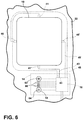
- FIG. 6 generally illustrates a variable transmittance window 10, and a window control unit 14, mounted in an airplane. As shown, the variable transmittance window 10 and the window control unit 14 are located adjacent to an inner reveal 22.
- the window control unit 14 includes a user input mechanism 18, including a first user input area 62, a second user input area 64, and a plurality of indicator lights 66. Also shown in hidden lines are a slave control circuitry 16 and electrochromic supplies 43, 43', 45, and 45' coupled to conducting structures 41, 41', 46, and 46', respectively, of the variable transmittance window 10.
- the user input mechanism 18 has a first user input area 62 and a second user input area 64 configured to be physically contacted by a user of the variable transmittance window 10 to change a selected transmittance state of the variable transmittance window 10.
- the plurality of indicator lights 66 are configured to display light indicating the current transmittance state of the window, the selected transmittance state of the window, whether the window is currently changing states, and/or whether the window control system is in an error state.
- the user input mechanism 18 can be made of a material that is impervious to moisture, and that is sealed to keep moisture and dirt from internal electrical and mechanical structures of user input mechanism 18 and slave control circuitry 16. Examples of variable transmittance windows for use in aircraft are shown in U.S. Patent No.
- the photovoltaic device may be disposed along the interior and/or exterior edge of the variable transmittance window 10 to generate electrical power from available cabin light and/or sunlight, respectively.
- the photovoltaic device may be disposed around a seal location.
- window fascia prevents the seal locations from being viewed by passengers located inside the aircraft.
- the seal locations on the outer side of the variable transmittance window 10 may provide an inconspicuous and aesthetic location for providing the photovoltaic device.
- the photovoltaic device may also be adhered or molded-in (integrated) to any foam structures around the window.
- the photovoltaic device may be coupled to a pressure pane of a variable transmittance window 10.
- the photovoltaic device is coupled to the pressure pane and is disposed proximate to the exterior of the plane.
- the photovoltaic device may be a transparent variety, thus allowing it to be directly applied to substantially an entire viewable window area of a variable transmittance window 10.
- reflectors configured to reflect light towards the photovoltaic device may be implemented in or in close proximity to the same area (e.g. seal or foam) in which the photovoltaic device is located to bolster the solar energy conversion process.
- variable transmittance window system 12 can be configured such that the window control units 14 can continue to be powered by the energy harvesting devices 20 even when the vehicle in which the system is installed is not operating. This allows the variable transmittance windows 10 to be darkened while the vehicle is inactive so as to block sunlight from entering and heating the inside of the vehicle cabin. Doing so may also prevent UV damage to items located in the cabin. Thus, if installed in an airplane, the windows can be darkened whenever the airplane is parked outside for extended periods thereby keeping the cabin cooler so that less energy may be required to cool the cabin when used again. Window control units 14 may receive power from the vehicle and may therefore determine that the vehicle is not active when power is no longer received from the vehicle.
- System 12 may be further configured to either clear windows 10 or maintain windows 10 in their current state for a predetermined time period after power is no longer received from the vehicle and then to automatically darken the windows after the predetermined time period.
- the windows 10 may be in a clear state for emergencies or certain vehicle operations such as landing of an airplane for safety reasons and then after a predetermined period (for example, one half hour) of nonoperation of the vehicle, may assume a darkened state.
- One way of implementing a method of automatically darkening the windows after a predetermined period after vehicle power is no longer provided is to prevent the energy harvesting device and/or energy storage device from providing power to the windows 10 until the predetermined period has expired. This may be accomplished using timer circuitry, which may be part of processing circuitry 35 or a separate circuit. If a separate timer circuit is used, a relay may be employed to prevent power from being supplied to driver circuitry 33 and hence windows 10. Alternatively, if timer circuitry is provided in processing circuitry 35, processing circuitry 35 may direct driver circuitry 33 to either clear windows 10 or maintain windows 10 in their current state for the predetermined time period and then may direct driver circuitry 33 to darken the windows 10 after expiration of the predetermined time period. In either case, window control circuitry 14 would include monitoring circuitry to monitor the power, voltage, and/or current on a vehicle power supply line so as to trigger the timer circuitry upon detection that power is no longer being supplied from the vehicle power line.
- Windows 10 may be darkened to a level that blocks most of the sunlight while still allowing occupants to see through the windows.
- energy storage device 30 may be charged by a power supply of the vehicle and an energy harvesting device 30 may not be provided.
- energy harvesting device 20 may directly power window control circuit 14 and the energy storage device 30 may not be provided. It is also possible that both energy harvesting device 20 and energy storage device 30 are provided.
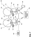
- a variable transmittance window system 100 for use in a vehicle is shown according to one embodiment and can include a plurality of variable transmittance windows 102.
- the transmittance of each window 102 can be controlled by a corresponding window control unit 104, which can be configured similarly to window control unit 14, described previously herein.
- Each window control unit 104 can be electrically coupled to a vehicle power supply 105 and can have a short range wireless transceiver 106.
- the short range wireless protocol can be Bluetooth Low Energy (BLE), Bluetooth Low Energy Mesh, Bluetooth, Zigbee, Wi-Fi, the like, or a combination thereof.
- one or more users can use a mobile device 108 (e.g., PDA, Smartphone, tablet, iPad®, iPod®, iPhone®, etc.) to communicate with the system 100 via an associated short range wireless transceiver 106.
- the mobile device 108 can be used to control a transmittance of a window 102, display operating characteristics of a window 102 (e.g., transmittance level, power consumption, power storage, etc.), the like, or a combination thereof.
- the mobile device 108 can be configured to control one window 102 (e.g., the passenger has access to control the window they are adjacent to), or a plurality of windows 102 (e.g., a crew member has access to control more than one or all of the windows as a cabin management system).
- one window 102 e.g., the passenger has access to control the window they are adjacent to
- a plurality of windows 102 e.g., a crew member has access to control more than one or all of the windows as a cabin management system.
- one or more of the window control units 104 can include a local control interface (LCI) 110 as a means for allowing a user to control the transmittance of a corresponding window 102.
- the LCI 110 can function similarly to the user input mechanism 18 described previously herein.
- the LCI 110 can include buttons 112 and 114, which may allow a user to increase and decrease the transmittance state of a corresponding window 102, respectively.
- the LCI 110 can also include a transmittance indicator 116, which can be embodied as a plurality of lights, each indicating a different transmittance level. The illumination pattern of the transmittance indicator 116 can be based on the selected transmittance as inputted via the LCI 110 and/or a mobile device 108.
- the system 100 can include a cabin control management system 118 in communication (e.g., wireless communication) with each window control unit 104.
- the cabin control management system 118 can be configured to control the window transmittance of one or more windows 102.
- the cabin control management system 118 can control the window transmittance to be substantially clear, substantially dark, or some intermediary and may do so by overriding a currently selected window transmittance. While the windows 102 are in an override transmittance state, the cabin control management system 118 can prompt the corresponding control units 104 to ignore or limit control commands received from a corresponding LCI 110 and/or mobile device 108.
- the cabin control management system 118 can remove the overriding conditions and allow passengers to regain full control of window transmittance via the LCI 110 or a mobile device 108.
- the inclusion of the cabin control management system 118 is particularly useful when system 100 is implemented in an aircraft. In that setting, the cabin control management system 118 can be accessed by a permitted user, such as a flight attendant and/or pilot, to allow the user to control the window transmittance of a single window, groups of windows, windows on a particular side or body region of the aircraft, all windows, etc. This is beneficial when a particular window transmittance may be necessary, such as during take-off and landing.
- the flight attendant and/or pilot can access the cabin control management system 118 to restrict a passenger's ability to control window transmittance. For example, when a movie is playing in a cabin or when passengers are sleeping, window transmittance may be limited to only darker transmittance states.
- the system 100 can include at least one window 102 having an icon 120 indicating the window transmittance is locked (e.g., controlled by the cabin management system 118).
- the icon 120 can be an illuminated icon on the window structure (e.g., window, bezel, adjacent cabin area), on the mobile device 108, the like, or a combination thereof. It should be appreciated that other icons indicating a variety of information can be implemented in other embodiments.
- a sensor 122 e.g., solar cell, photodiode, etc.
- a sensor 122 can be configured to detect an exterior light level. Additionally or alternatively, the sensor 122, or another sensor, can be positioned and configured to detect an interior light level. In this manner, the corresponding window 102 can be controlled to maintain an interior light level.
- the system 100 can be configured so that any controller (e.g., window control unit 104) can be reconfigured to be a master controller.
- Any controller e.g., window control unit 104
- An example is to have a predefined button sequence that changes the functionality of the controller (e.g., actuate buttons 112 and 114 at the same time for a period of time).
- the system 100 is implemented in an aircraft.
- the sensor 112 can correspond to solar cells that are configured to be able to supply sufficient power to approximately completely darken the corresponding window 102 while the aircraft is at a cruising altitude.
- the number and/or surface area of solar cells is based upon the available solar radiation that can be received at a cruising altitude of an aircraft as opposed to the aircraft being on the ground.
- the solar cells can be configured to supply adequate power to partially dim the windows 102 while the aircraft is on the ground.
- about 4 to 6 solar cells can be used, wherein each solar cell has an area of about 143 mm 2 .
Landscapes
- Physics & Mathematics (AREA)
- Nonlinear Science (AREA)
- General Physics & Mathematics (AREA)
- Optics & Photonics (AREA)
- Engineering & Computer Science (AREA)
- Civil Engineering (AREA)
- Structural Engineering (AREA)
- Electrochromic Elements, Electrophoresis, Or Variable Reflection Or Absorption Elements (AREA)
Description
- The present invention generally relates to variable transmittance windows. More specifically, the present invention relates to a variable transmittance system in which variable transmittance windows are powered using energy harvesting devices.
- Document
WO 2012/156779 A1 relates to a window darkening system in which the windows in a vehicle are enabled to be darkened automatically and/or manually. - Document
U.S. 2011/0163866 A1 relates to a sun protection system for an automotive vehicle that includes LCD zones laminated in one or more glazings of the vehicle. - Document
U.S. 6,317,248 B1 relates to edge busbars for electrically powered cells. Signals supplied to the busbars to control an electrochromic device are controlled by a switching power supply that allows the maintaining of the color of the electrochromic device without application of continuous power. - Document
U.S. 2008/0239451 A1 relates to electrically dimmable windows for aircraft. The electrically dimmable windows are powered by energy harvesting devices on-board the aircraft. - Document
U.S. 2008/0230653 A1 relates to an electrically controlled dimmable window for aircraft. Power for controlling the window is derived from an energy harvesting device that generates power by converting thermal gradients, motion/vibration, or light energy present near the window. - The invention is set forth by the subject-matter of the independent claim.
- According to at least one aspect of the present invention, a variable transmittance window system is provided and includes at least one variable transmittance window. At least one energy harvesting device is included for generating an electrical power. A power supply circuitry is included for maximizing the electrical power. At least one energy storage device is included and is configured to be charged by the electrical power. A slave control circuitry is included for controlling a transmittance state of the at least one variable transmittance window, the slave control circuitry being powered by at least one of the power supply circuitry and the at least one energy storage device. A master control circuitry is included and is configured to monitor the slave control circuitry, wherein the master control circuitry is operable to issue a wireless override signal to the slave control circuitry such that the slave control circuitry changes the transmittance state of the at least one variable transmittance window to an override transmittance state.
- According to at least another aspect of the present invention, a variable transmittance window system is provided and includes at least one variable transmittance window. At least one energy harvesting device is included for generating electrical power. At least one energy storage device is included and is configured to be charged by the electrical power. A window control circuitry is included for controlling a transmittance state of the at least one variable transmittance window, the window control circuitry being powered by a power supply of the vehicle and at least one of the at least one energy harvesting device and the at least one energy storage device. A monitoring circuit is included and is communicatively coupled to the window control circuitry for monitoring the supply of power from the vehicle and for detecting that power is no longer being supplied from the vehicle power supply, wherein the window control circuitry darkens the at least one variable transmittance window after a
predetermined time period after detection that power is no longer being supplied from the vehicle power supply. - According to at least another aspect of the present invention, a variable transmittance window system is provided and includes at least one variable transmittance window. At least one energy harvesting device is included for generating electrical power. A window control circuitry is included for controlling a transmittance state of the at least one variable transmittance window, the window control circuitry being powered by a power supply of the vehicle and the at least one energy harvesting device. A monitoring circuit is provided and is communicatively coupled to the window control circuitry for monitoring the supply of power from the vehicle and for detecting that power is no longer being supplied from the vehicle power supply. The window control circuitry darkens the at least one variable transmittance window after a predetermined time period after detection that power is no longer being supplied from the vehicle power supply.
- These and other features, advantages, and objects of the present invention will be further understood and appreciated by those skilled in the art by reference to the following specification, claims, and appended drawings.
- The present invention will be become more fully understood from the detailed description and the accompanying drawings, wherein:
-
FIG. 1 is a general illustration of multi-passenger vehicles incorporating variable transmission windows, according to one embodiment of the present invention; -
FIG. 2 is a block diagram generally illustrating a system for controlling variable transmission windows, according to the present invention; -
FIG. 3 is a block diagram generally illustrating one embodiment of a slave control circuitry and an user input mechanism for controlling a variable transmission window, that may be used to implement the system for controlling a variable transmission window shown inFIG. 2 ; -
FIG. 4 is a simplified block diagram generally illustrating another embodiment of the slave control circuitry; -
FIG. 5 is a simplified block diagram generally illustrating yet another embodiment of the slave control circuitry; -
FIG. 6 is a front view generally illustrating a variable transmission window and system for controlling the variable transmission window according to one embodiment of the present invention; and -
FIG. 7 is a block diagram generally illustrating a system for controlling variable transmission windows, according to at least one embodiment of the present invention. - Reference will now be made in detail to the present preferred embodiments of the invention, examples of which are illustrated in the accompanying drawings. Wherever possible, the same reference numerals will be used throughout the drawings to refer to the same or like parts. In the drawings, the depicted structural elements are not to scale and certain components are enlarged relative to the other components for purposes of emphasis and understanding.
- For purposes of description herein, the terms "upper," "lower," "right," "left," "rear," "front," "vertical," "horizontal," "top," "bottom," and derivatives thereof shall relate to the invention as shown in the drawings. However, it is to be understood that the invention may assume various alternative orientations, except where expressly specified to the contrary. It is also to be understood that the specific device illustrated in the attached drawings and described in the following specification is simply an exemplary embodiment of the inventive concepts defined in the appended claims. Hence, specific dimensions, proportions, and other physical characteristics relating to the embodiment disclosed herein are not to be considered as limiting, unless the claims expressly state otherwise.
- The present invention relates to a variable transmittance window system in which one or more variable transmittance windows are powered using energy harnessing devices. Examples of variable transmittance windows include windows that are able to change their transmittance based on electrical signals applied to the window, such as the windows generally described in
U.S. Patent No. 6,407,847 entitled "ELECTROCHROMIC MEDIUM HAVING A COLOR STABILITY,"U.S. Patent No. 6,239,898 entitled "ELECTROCHROMIC STRUCTURES,"U.S. Patent No. 6,597,489 entitled "ELECTRODE DESIGN FOR ELECTROCHROMIC DEVICES," andU.S. Patent No. 5,805,330 entitled "ELECTRO-OPTIC WINDOW INCORPORATING A DISCRETE PHOTOVOLTAIC DEVICE," the entire disclosures of each of which are incorporated herein by reference. Examples of electrochromic devices that may be used in windows are described inU.S. Patent No. 6,433,914 entitled "COLOR-STABILIZED ELECTROCHROMIC DEVICES,"U.S. Patent No. 6,137,620 entitled "ELECTROCHROMIC MEDIA WITH CONCENTRATION-ENHANCED STABILITY, PROCESS FOR THE PREPARATION THEREOF AND USE IN ELECTROCHROMIC DEVICES,"U.S. Patent No. 5,940,201 entitled "ELECTROCHROMIC MIRROR WITH TWO THIN GLASS ELEMENTS AND A GELLED ELECTROCHROMIC MEDIUM," andU.S. Patent Application Publication No. 2006/0056003 entitled "VEHICULAR REARVIEW MIRROR ELEMENTS AND ASSEMBLIES INCORPORATING THESE ELEMENTS," the entire disclosures of each of which are incorporated herein by reference. Other examples of variable transmittance windows and systems for controlling them are disclosed inU.S. Patent No. 7,085,609 , entitled "VARIABLE TRANSMITTANCE WINDOW CONSTRUCTIONS,"U.S. Patent No. 6,567,708 entitled "SYSTEM TO INTERCONNECT, LINK, AND CONTROL VARIABLE TRANSMITTANCE WINDOWS AND VARIABLE TRANSMITTANCE WINDOW CONSTRUCTIONS," the entire disclosures of each of which are incorporated herein by reference. -
FIG. 1 is a graphical representation of several vehicles employing one or morevariable transmittance windows 10. These vehicles employing thevariable transmittance windows 10 include, for example, anaircraft 2, a bus 4, and atrain 6. As will be described in greater detail below, each of the vehicles generally illustrated inFIG. 1 may also include a variable transmittance window control system for controlling thevariable transmittance windows 10. WhileFIG. 1 illustrates a few vehicles equipped with thevariable transmittance windows 10, it should be appreciated that thevariable transmittance windows 10 may be similarly equipped in other vehicles designed to hold passengers not mentioned herein. Further, it should also be appreciated that thevariable transmittance windows 10 may be equipped on stationary objects such as buildings, homes, and the like. As such, they too are eligible to use the variable transmittance window control system described herein. -
FIG. 2 generally illustrates a variable transmittance window system including thevariable transmittance windows 10 that may be equipped on an aircraft, along with a variable transmittancewindow control system 12 that is electrically coupled to thevariable transmittance windows 10 for controlling the transmittance state of thevariable transmittance windows 10. The variable transmittancewindow control system 12 includes a plurality ofwindow control units 14 each coupled to at least one correspondingvariable transmittance windows 10. Eachwindow control unit 14 includes aslave control circuitry 16 for controlling the transmittance state of an associatedvariable transmittance window 10. Eachwindow control unit 14 also includes auser input mechanism 18 coupled to theslave control circuitry 16 for providing a user input to theslave control circuitry 16 to change the transmittance state of the associatedvariable transmittance window 10. - Each
window control unit 14 is coupled to one or moreenergy harvesting devices 20 configured to produce electrical power, which may be used to power theslave control circuitry 16, theuser input mechanism 18, and the associatedvariable transmittance window 10 of eachwindow control unit 14. In the illustrated embodiment, theenergy harvesting device 20 associated with eachwindow control unit 14 is coupled to theslave control circuitry 16 such that theslave control circuit 16 is responsible for providing electrical power to the associatedvariable transmittance window 10. In one embodiment, theslave control circuitry 16 provides power to theuser input mechanism 18 and is also configured to monitor the circuitry included in theuser input mechanism 18. - Referring still to
FIG. 2 , theslave control circuitry 16 of eachwindow control units 14 is in wireless communication with amaster control circuitry 22. Themaster control circuitry 22 is configured to monitor wireless signals transmitted from theslave control circuitry 16 and to transmit wireless signals to theslave control circuitry 16. To that end, both theslave control circuitry 16 and themaster control circuitry 22 should include processing circuitry, including programmable logic, memory, and interface circuitry, to permit them both to generate, send, receive, and decode transmitted wireless signals. - The
master control circuitry 22 is configured to issue wireless override signals to thewindow control units 14 to direct theslave control circuitry 16 of eachwindow control unit 14 to change the transmittance state of the associatedvariable transmittance window 10. The transmittance state is selected by the wireless override signal sent by themaster control circuitry 22. Wireless override signals issued to theslave control circuitry 16 may include signals to cause one, some, or all of thevariable transmittance windows 10 to change to an override transmittance state. In so doing, the one or morevariable transmittance windows 10 may darken, lighten, go to the darkest state, go to the lightest state, or go to a predetermined intermediate transmittance state in an incremental manner. Further, themaster control circuitry 22 may direct allwindow control units 14 to alter the states of theirvariable transmittance windows 10 at the same time, one at a time, or in groups, in order to minimize system power loading, to optimize passenger comfort or to control lighting levels. - With respect to vehicles equipped with variable transmittance windows, the ability to override an existing transmittance state is especially useful. For instance, with respect to the aircraft setting described herein, a pilot or flight attendant may operate the
master control circuitry 22 and exercise its overriding capabilities during take-off and landing by causing all applicablevariable transmittance windows 10 to return to a lightened state. In another instance, themaster control circuitry 22 may be operated to force all applicablevariable transmittance windows 10 to darken in the event a movie is playing and/or passengers are sleeping. In any event, themaster control circuitry 22 may be configured to maintain the override transmittance state for a predetermined period determined by themaster control circuitry 22 or until the pilot or flight attendant removes the override. Thereafter, passengers seated next to one of thevariable transmittance windows 10 will have the option to change its transmittance state to one providing greater individual comfort. - Although the
variable transmittance windows 10 are shown each having their ownslave control circuitry 16,user input mechanism 18, andenergy harvesting device 20, it should be appreciated that a variety of combinations are possible. For instance, in an alternative embodiment, oneuser input mechanism 18 may change the transmittance state of multiplevariable transmittance windows 10. In another alternate embodiment, a transmittance state selected by a user via theuser input mechanism 18 of onewindow control unit 14 may be wirelessly transmitted to otherwindow control units 14 via interaction between theslave control circuitries 16 of the participatingwindow control units 14. Theslave control circuitries 16 may relay messages intended for one another to extend the range of the wireless network. In another embodiment, oneuser input mechanism 18 may be directly coupled to theslave control circuitry 16 of more than onewindow control unit 14. In still another embodiment, oneslave control circuitry 16 may control multiplevariable transmittance windows 10. In still another embodiment, oneenergy harvesting device 20 may be coupled to more than onewindow control units 14. In yet another embodiment, more than oneenergy harvesting device 20 may be coupled to one or morewindow control units 14. -
FIG. 3 provides a high level block diagram of the circuitry included in an exemplarywindow control unit 14. As previously described, thewindow control unit 14 includes aslave control circuitry 16 coupled to auser input mechanism 18. In addition, thewindow control unit 14 is electrically coupled to at least oneenergy harvesting device 20 and at least onevariable transmittance window 10 and may be in wireless communication with amaster control circuitry 22. - In the illustrated embodiment, the
energy harvesting device 20 may include a photovoltaic device (e.g. solar cell) for converting electromagnetic radiation into electrical power. The photovoltaic device may be constructed from a variety of materials such as, but not limited to, cadmium telluride (CdTe), silicon (Si), gallium arsenide (GaAs), and copper indium gallium selenide (CIGS) or a transparent photovoltaic cell such as, but not limited to, a heterojunction organic photovoltaic (OPV) cell, demonstrating peak-absorption in the ultraviolet (UV and/or near-infrared (NIR)). In one embodiment, an OPV cell could be deposited on a portion of the viewable window area or its entirety. In another embodiment, the photovoltaic device is constructed from a material (e.g. cadmium telluride) having high temperature performance capabilities and the ability to be sputtered on a surface such as the perimeter of the window. In this manner, the photovoltaic device may be provided on exposed surfaces of thevariable transmittance window 10 and positioned to receive electromagnetic radiation in the form of sunlight and/or cabin lighting. Additionally, or alternatively, theenergy harvesting device 20 may include a thermoelectric device such as, but not limited to, a Peltier device, for generating electrical power via a temperature difference between the outside and the inside of an aircraft at cruising altitudes, or an electromagnetic or piezoelectric device configured to convert vibration into electrical power. To generate electrical power, the thermoelectric device may be positioned between two materials of thevariable transmittance window 10 or window assembly, wherein the two materials having different temperatures. The option of generating electrical power from both solar and thermoelectric sources may be particularly beneficial when conditions are favorable for one source, but not the other. For instance, during sunset and sunrise, it may be difficult to generate sufficient electrical power through the use of a photoelectric device alone. The same may be said for when a bright moon is present. In these circumstances, the ability to generate electrical power from a thermoelectric, electromagnetic, and/or piezoelectric device may better afford a passenger with the option of changing the transmittance state of avariable transmittance window 10 to block light entry. On the other hand, when an aircraft is grounded or flying at low altitudes, the thermoelectric effect is less pronounced, which may prevent sufficient electrical power from being generated if using the thermoelectric device alone. For those circumstances, the inclusion of a photovoltaic device for power generation may enable continued usage of thevariable transmittance window 10. - As shown in
FIG. 3 , theslave control circuitry 16 includes apower supply circuitry 26 electrically coupled to at least oneenergy harvesting device 20 and configured to maximize the generated power output from theenergy harvesting device 20. Thepower supply circuitry 26 may include a maximum power point control device (MPPC) 28 configured to sample electrical output from theenergy harvesting device 20 and apply a resistance thereto to obtain a maximum electrical power output. Anenergy harvesting device 20 such as a solar cell has an output voltage that is a function of its load current. The output voltage V is maximized at zero load current (open circuit) and the output current is maximized at zero volts output (short circuit conditions). Neither limit case delivers a significant amount of power P=V∗I. At some intermediate load current, the output power P will be maximized. A simple method for approximately maximizing P is to limit the current drawn from theenergy harvesting 20 whenever the output voltage drops below a predetermined voltage thus preventing the output voltage from collapsing toward zero. Other more sophisticated maximization schemes are known in the art and can be used for slightly better energy recovery. Once approximated, the maximum electrical power output is used for powering thewindow control unit 14 and/or charging anenergy storage device 30 for later use. - Additionally, or alternatively, the
power supply circuitry 26 may also include a switch-mode power supply (SMPS) 31 electrically coupled to the maximum powerpoint control device 28 and theenergy storage device 30. The switch-mode power supply 31 is configured to receive electrical power from the maximum powerpoint control device 28 and may adjust the corresponding voltage level according to the consumption needs of thewindow control unit 14. Electrical energy at the adjusted voltage level may then be used to power thewindow control unit 14 and/or charge theenergy storage device 30 for later use. The switchmode power supply 31 may include a buck-boost converter for either increasing or decreasing voltage to a desired level. Electrochromic windows can exhibit considerable capacitance (multiple Farads) and hence store significant energy in their darkened state. Alternatively, thedriver circuitry 33 may include a synchronous buck-boost converter to provide an energy recovery mechanism for when thevariable transmittance window 10 is cleared, in which case some electrical power is recovered from thevariable transmittance window 10 and stored to theenergy storage device 30. - The
energy storage device 30 includes, but is not limited to, a capacitor, a super capacitor and/or a rechargeable battery. Theenergy storage device 30 is electrically coupled to adriver circuitry 33 and aprocessing circuitry 35 of theslave control circuitry 16, and is configured to power the same. It should be appreciated that more than onepower supply circuitry 26 and/orenergy storage device 30 may be implemented in thewindow control unit 14. In one embodiment, thedriver circuitry 33 and/or theprocessing circuitry 35 are provided with their ownpower supply circuitry 26 and/orenergy storage device 30. - For purposes of illustration, and not limitation, one embodiment of a
slave control circuitry 16 is shown inFIG. 4 , wherein the driver circuitry 33 (shown in an H-bridge configuration) and theprocessing circuitry 35 each have apower supply circuitry energy storage device FIG. 4 for exemplary purposes, thepower supply circuitry 26b of theprocessing circuitry 35 is supplied a solar voltage Vsolar directly from the energy harvesting device 20 (shown as a photovoltaic device), and outputs a regulated voltage Vreg, which is applied to theprocessing circuitry 35 and/or stored in theenergy storage device 30b, whereas thepower supply circuitry 26a of thedriver circuitry 33 may be supplied with either the solar voltage Vsolar or the regulated voltage Vreg and outputs a voltage to be applied to thedriver circuitry 33 and/or stored in the energy storing device 30a.Power supply circuitry power circuit 26a can use a linear power supply instead of the switch-mode power supply. - With respect to the illustrated embodiment, block 200 represents a subsection of the
microcontroller 50 and functions to control thedriver circuitry 33. In one embodiment, thedriver circuitry 33 is a synchronous buck converter to enable energy stored in a corresponding darkenedvariable transmittance window 10 to be returned toenergy storage device 30b. ARESET circuitry 202 can be provided to controlswitches 204 that are powered by back voltage Vback, which is derived from the regulated voltage Vreg through adiode 206. In operation, theswitches 204 pass ECH2 and ECH4 gate signals through to ECH2' and ECH4' so long as the voltage, Vsolar or Vreg, supplied to theRESET circuitry 202 is above a preset voltage threshold. When the voltage supplied to theRESET circuitry 202 falls below a preset voltage threshold, the ECH2' and ECH4' gate signals are connected to the back voltage Vback, which is held up by anenergy storage capacitor 208. Theenergy storage capacitor 208 provides sufficient energy such that MOSFETs associated with ECH2' and ECH4' are turned on long enough to clear the correspondingvariable transmittance window 10. - As is exemplarily shown in
FIG. 5 , thepower supply circuitry 26b of theprocessing circuitry 35 may be embodied as an integrated unit, and is exemplarily shown as a Linear Technology LTC3105 converter and maximum power point control, and thepower supply circuitry 26a of thedriver circuitry 33 is exemplarily embodied as a maximum power point control device and a synchronous converter (e.g., synchronous buck converter). With respect toFIGS. 4 and5 , it is to be understood that some components described herein have been omitted for the sake of clarity. - Referring back to
FIG. 3 , thedriver circuitry 33 is configured to receive control signal information, including, but not limited to, a desired transmittance state for thevariable transmittance window 10 from theprocessing circuitry 35. Thedriver circuitry 33 provides anelectrochromic supply 43, also referred to as ANODE_TOP, and an electrochromic supply 43', also referred to as ANODE_BOTTOM, to conductingstructures structures conductive layer 36 deposited on asubstrate 34 that is part of an electrochromic element 47. The transparent electricallyconductive layer 36 and thesubstrate 34 are collectively referred to as a firstcoated substrate 48.Driver circuitry 33 also provides anelectrochromic supply 45, also referred to as CATHODE_LEFT, and an electrochromic supply 45', also referred to as CATHODE_RIGHT, to conductingstructures 46 and 46', respectively. Conductingstructures 46 and 46' are coupled to a transparent electricallyconductive layer 38 deposited on asubstrate 44 that is part of an electrochromic element 47. The transparentconductive layer 38 and thesubstrate 44 are collectively referred to as a secondcoated substrate 42. Thedriver circuitry 33 may include an H-bridge circuitry and varies the current and/or voltage supplied by the electrochromic supplies 43, 43', 45, and 45' to vary the electronic potential of the conductingstructures conductive layers driver circuitry 33 by theprocessing circuitry 35. - As previously described, the
processing circuitry 35 is generally configured to send control signals indicative of a selected transmittance state of avariable transmittance window 10 to thedriver circuitry 33. In addition, theprocessing circuitry 35 can also be configured to receive status information from thedriver circuitry 33. This status information includes, but is not limited to, the transmittance state of thevariable transmittance window 10, power being supplied to thevariable transmittance window 10 by thedriver circuitry 33, and status and error condition information associated with thedriver circuitry 33 and/or thevariable transmittance window 10. In the illustrated embodiment, theprocessing circuitry 35 includes amicrocontroller 50 for controlling thewindow control unit 14. Themicrocontroller 50 includes memory for storing instructions and algorithms necessary to control thewindow control unit 14. Themicrocontroller 50 also includes logic for executing the instructions and algorithms stored in the memory. Themicrocontroller 50 is shown coupled to afirst transceiver 52, which is wirelessly coupled to asecond transceiver 53 of themaster control circuitry 22. Thefirst transceiver 52 is configured to receive wireless signals from themaster control circuitry 22, decode them, and provide them to themicrocontroller 50. Likewise, thesecond transceiver 53 is configured to receive wireless signals from themicrocontroller 50, decode them, and provide them to themaster control circuitry 22. -
Microcontroller 50 is shown having multiple inputs, multiple outputs, and multiple combined input/output lines for communicating with, and controlling, other devices in thewindow control unit 14, such as theuser input mechanism 18, thepower supply circuitry 26, and thedriver circuitry 33. In addition,microcontroller 50 is shown coupled to awindow transmission circuitry 54 for determining the transmittance state of thevariable transmittance window 10. Thetransmission circuitry 54 includes alight sensor 55 and alight source 56. In operation, thelight sensor 55 and thelight source 56 are positioned on opposite sides of thevariable transmittance window 10. In this arrangement, themicrocontroller 50 determines the transmittance state of thevariable transmittance window 10 by virtue of the amount of light emanating from thelight source 56 that is detected by thelight sensor 55. - The
microcontroller 50 is also shown coupled to an exteriorlight sensor 57 and an interiorlight sensor 58, which provide brightness information related to the outside of an aircraft and the interior cabin, respectively. The brightness information may be used to implement a cabin brightness control system for adjusting the cabin brightness based on directions provided by themaster control circuitry 22 to themicrocontroller 50. For instance, on flights crossing several time zones, passengers often sleep during daytime hours. In such a situation, a pilot or flight attendant may operate themaster control circuitry 22 to issue an override signal for adjusting the cabin brightness by causing one or morevariable transmittance windows 10 to darken. Thus, by monitoring the brightness information, themaster control circuitry 22 may determine the location of the sun relative to the aircraft and cause the transmittance state of anyvariable transmittance window 10 to be adjusted accordingly. - The
microcontroller 50 is also shown coupled to adropout detection circuitry 79. Thedropout detection circuitry 79 is configured to store a charge on a dropout energy storage device 80 (e.g. rechargeable battery, capacitor, and/or super capacitor) while power is being supplied to thewindow control unit 14. When power is removed from thewindow control unit 14, the charge on the drop outenergy storage device 80 decays over time. When power is reapplied to thewindow control unit 14, the amount of charge left on the dropoutenergy storage device 80 is provided as input to themicrocontroller 50, and is used by themicrocontroller 50 to determine the approximate amount of time that power was removed from thewindow control unit 14. If the amount of time that power was removed fromwindow control unit 14 is small, e.g., two seconds or less, themicrocontroller 50 directs thevariable transmittance window 10 to return to the state that it was in prior to power being removed. On the other hand, if themicrocontroller 50 determines that power has been removed for a longer period of time (e.g., longer than two seconds), themicrocontroller 50 directs thevariable transmittance window 10 to go to a predetermined transmittance state, such as, but not limited to, a clear state. - The
microcontroller 50 also includes areset circuitry 81. Thereset circuitry 81 monitors the voltage provided by thepower supply circuitry 26 to determine when the voltage falls below a reset voltage threshold. If so, thereset circuitry 81 issues a reset signal for a predetermined period of time. This reset signal is used to reset themicrocontroller 50, and is also coupled to thedriver circuitry 33 to cause the H-bridge circuitry in thedriver circuitry 33 to short theelectrochromic supply 43 and theelectrochromic supply 45 to ground, causing thevariable transmittance window 10 to clear. - As is further shown in
FIG. 3 , themicrocontroller 50 of theprocessing circuitry 35 is electrically coupled with theuser input mechanism 18. Themicrocontroller 50 receives user input signals from theuser input mechanism 18 enabling a passenger to change the transmittance state of thevariable transmittance window 10. The user input signals may be inputted in any known manner such as, but not limited to, push buttons, switches, capacitive touch, etc., and theuser input mechanism 18 may include various indication devices such as lights, display devices (e.g. LCD display), etc. Indication signals from themicrocontroller 50 are provided to theuser input mechanism 18 for providing a passenger with status information related to thevariable transmittance window 10. For instance, the indication signals may be used to communicate the current transmittance state of thevariable transmittance window 10, when a request for a new transmittance state has been received from a user, when a request for a new transmittance state has been received from themaster control circuitry 22, when an override signal has been received from themaster control circuitry 22, and when an error condition exists in theuser input mechanism 18 or other component associated with thewindow control unit 14. The indication signals may be expressed through the activation of one or more lights and/or messages displayed on the display device. -
FIG. 6 generally illustrates avariable transmittance window 10, and awindow control unit 14, mounted in an airplane. As shown, thevariable transmittance window 10 and thewindow control unit 14 are located adjacent to aninner reveal 22. Thewindow control unit 14 includes auser input mechanism 18, including a firstuser input area 62, a seconduser input area 64, and a plurality of indicator lights 66. Also shown in hidden lines are aslave control circuitry 16 andelectrochromic supplies structures variable transmittance window 10. As shown, theuser input mechanism 18 has a firstuser input area 62 and a seconduser input area 64 configured to be physically contacted by a user of thevariable transmittance window 10 to change a selected transmittance state of thevariable transmittance window 10. The plurality of indicator lights 66 are configured to display light indicating the current transmittance state of the window, the selected transmittance state of the window, whether the window is currently changing states, and/or whether the window control system is in an error state. Theuser input mechanism 18 can be made of a material that is impervious to moisture, and that is sealed to keep moisture and dirt from internal electrical and mechanical structures ofuser input mechanism 18 andslave control circuitry 16. Examples of variable transmittance windows for use in aircraft are shown inU.S. Patent No. 7,990,603 entitled "VARIABLE TRANSMISSION WINDOW SYSTEM," andU.S. Provisional Application No. 61/759,009 - If using a photovoltaic device for a selected
energy harvesting device 20, the photovoltaic device may be disposed along the interior and/or exterior edge of thevariable transmittance window 10 to generate electrical power from available cabin light and/or sunlight, respectively. In another embodiment, the photovoltaic device may be disposed around a seal location. With respect to somevariable transmittance window 10 constructions, window fascia prevents the seal locations from being viewed by passengers located inside the aircraft. However, the seal locations on the outer side of thevariable transmittance window 10 may provide an inconspicuous and aesthetic location for providing the photovoltaic device. In another embodiment, the photovoltaic device may also be adhered or molded-in (integrated) to any foam structures around the window. In yet another embodiment, the photovoltaic device may be coupled to a pressure pane of avariable transmittance window 10. In one embodiment, the photovoltaic device is coupled to the pressure pane and is disposed proximate to the exterior of the plane. In still another embodiment, the photovoltaic device may be a transparent variety, thus allowing it to be directly applied to substantially an entire viewable window area of avariable transmittance window 10. With respect to any of the aforementioned embodiments, reflectors configured to reflect light towards the photovoltaic device may be implemented in or in close proximity to the same area (e.g. seal or foam) in which the photovoltaic device is located to bolster the solar energy conversion process. - The variable
transmittance window system 12 can be configured such that thewindow control units 14 can continue to be powered by theenergy harvesting devices 20 even when the vehicle in which the system is installed is not operating. This allows thevariable transmittance windows 10 to be darkened while the vehicle is inactive so as to block sunlight from entering and heating the inside of the vehicle cabin. Doing so may also prevent UV damage to items located in the cabin. Thus, if installed in an airplane, the windows can be darkened whenever the airplane is parked outside for extended periods thereby keeping the cabin cooler so that less energy may be required to cool the cabin when used again.Window control units 14 may receive power from the vehicle and may therefore determine that the vehicle is not active when power is no longer received from the vehicle.System 12 may be further configured to eitherclear windows 10 or maintainwindows 10 in their current state for a predetermined time period after power is no longer received from the vehicle and then to automatically darken the windows after the predetermined time period. In this way, thewindows 10 may be in a clear state for emergencies or certain vehicle operations such as landing of an airplane for safety reasons and then after a predetermined period (for example, one half hour) of nonoperation of the vehicle, may assume a darkened state. - One way of implementing a method of automatically darkening the windows after a predetermined period after vehicle power is no longer provided, is to prevent the energy harvesting device and/or energy storage device from providing power to the
windows 10 until the predetermined period has expired. This may be accomplished using timer circuitry, which may be part ofprocessing circuitry 35 or a separate circuit. If a separate timer circuit is used, a relay may be employed to prevent power from being supplied todriver circuitry 33 and hencewindows 10. Alternatively, if timer circuitry is provided inprocessing circuitry 35, processingcircuitry 35 may directdriver circuitry 33 to eitherclear windows 10 or maintainwindows 10 in their current state for the predetermined time period and then may directdriver circuitry 33 to darken thewindows 10 after expiration of the predetermined time period. In either case,window control circuitry 14 would include monitoring circuitry to monitor the power, voltage, and/or current on a vehicle power supply line so as to trigger the timer circuitry upon detection that power is no longer being supplied from the vehicle power line. - Another approach to darkening the windows during nonuse while allowing occupants to see out the windows for safety purposes during emergencies or certain vehicle operations such as the landing of an airplane, is to partially darken
windows 10 following detection that power is no longer being supplied from the vehicle power line.Windows 10 may be darkened to a level that blocks most of the sunlight while still allowing occupants to see through the windows. - In some of the embodiments above,
energy storage device 30 may be charged by a power supply of the vehicle and anenergy harvesting device 30 may not be provided. In other embodiments,energy harvesting device 20 may directly powerwindow control circuit 14 and theenergy storage device 30 may not be provided. It is also possible that bothenergy harvesting device 20 andenergy storage device 30 are provided. - Referring to
FIG. 7 , a variabletransmittance window system 100 for use in a vehicle is shown according to one embodiment and can include a plurality ofvariable transmittance windows 102. The transmittance of eachwindow 102 can be controlled by a correspondingwindow control unit 104, which can be configured similarly towindow control unit 14, described previously herein. Eachwindow control unit 104 can be electrically coupled to avehicle power supply 105 and can have a shortrange wireless transceiver 106. By way of explanation and not limitation, the short range wireless protocol can be Bluetooth Low Energy (BLE), Bluetooth Low Energy Mesh, Bluetooth, Zigbee, Wi-Fi, the like, or a combination thereof. - For purposes of explanation and not limitation, in operation, one or more users can use a mobile device 108 (e.g., PDA, Smartphone, tablet, iPad®, iPod®, iPhone®, etc.) to communicate with the
system 100 via an associated shortrange wireless transceiver 106. In operation, themobile device 108 can be used to control a transmittance of awindow 102, display operating characteristics of a window 102 (e.g., transmittance level, power consumption, power storage, etc.), the like, or a combination thereof. Themobile device 108 can be configured to control one window 102 (e.g., the passenger has access to control the window they are adjacent to), or a plurality of windows 102 (e.g., a crew member has access to control more than one or all of the windows as a cabin management system). - According to at least one embodiment, one or more of the
window control units 104 can include a local control interface (LCI) 110 as a means for allowing a user to control the transmittance of acorresponding window 102. TheLCI 110 can function similarly to theuser input mechanism 18 described previously herein. TheLCI 110 can includebuttons corresponding window 102, respectively. TheLCI 110 can also include atransmittance indicator 116, which can be embodied as a plurality of lights, each indicating a different transmittance level. The illumination pattern of thetransmittance indicator 116 can be based on the selected transmittance as inputted via theLCI 110 and/or amobile device 108. - According to at least one embodiment, the
system 100 can include a cabincontrol management system 118 in communication (e.g., wireless communication) with eachwindow control unit 104. The cabincontrol management system 118 can be configured to control the window transmittance of one ormore windows 102. In one embodiment, the cabincontrol management system 118 can control the window transmittance to be substantially clear, substantially dark, or some intermediary and may do so by overriding a currently selected window transmittance. While thewindows 102 are in an override transmittance state, the cabincontrol management system 118 can prompt thecorresponding control units 104 to ignore or limit control commands received from acorresponding LCI 110 and/ormobile device 108. When it is no longer necessary for thewindows 102 to be in the override transmittance state, the cabincontrol management system 118 can remove the overriding conditions and allow passengers to regain full control of window transmittance via theLCI 110 or amobile device 108. The inclusion of the cabincontrol management system 118 is particularly useful whensystem 100 is implemented in an aircraft. In that setting, the cabincontrol management system 118 can be accessed by a permitted user, such as a flight attendant and/or pilot, to allow the user to control the window transmittance of a single window, groups of windows, windows on a particular side or body region of the aircraft, all windows, etc. This is beneficial when a particular window transmittance may be necessary, such as during take-off and landing. Alternatively, the flight attendant and/or pilot can access the cabincontrol management system 118 to restrict a passenger's ability to control window transmittance. For example, when a movie is playing in a cabin or when passengers are sleeping, window transmittance may be limited to only darker transmittance states. - According to at least one embodiment, the
system 100 can include at least onewindow 102 having anicon 120 indicating the window transmittance is locked (e.g., controlled by the cabin management system 118). Theicon 120 can be an illuminated icon on the window structure (e.g., window, bezel, adjacent cabin area), on themobile device 108, the like, or a combination thereof. It should be appreciated that other icons indicating a variety of information can be implemented in other embodiments. - According to at least one embodiment, a sensor 122 (e.g., solar cell, photodiode, etc.) can be configured to detect an exterior light level. Additionally or alternatively, the
sensor 122, or another sensor, can be positioned and configured to detect an interior light level. In this manner, the correspondingwindow 102 can be controlled to maintain an interior light level. - According to at least one embodiment, the
system 100 can be configured so that any controller (e.g., window control unit 104) can be reconfigured to be a master controller. An example is to have a predefined button sequence that changes the functionality of the controller (e.g., actuatebuttons - According to at least one embodiment, the
system 100 is implemented in an aircraft. Thesensor 112 can correspond to solar cells that are configured to be able to supply sufficient power to approximately completely darken thecorresponding window 102 while the aircraft is at a cruising altitude. Thus, the number and/or surface area of solar cells is based upon the available solar radiation that can be received at a cruising altitude of an aircraft as opposed to the aircraft being on the ground. The solar cells can be configured to supply adequate power to partially dim thewindows 102 while the aircraft is on the ground. By way of explanation and not limitation, about 4 to 6 solar cells can be used, wherein each solar cell has an area of about 143 mm2. - The above description is considered that of the preferred embodiments only. Modifications of the invention will occur to those skilled in the art and to those who make or use the invention. Therefore, it is understood that the embodiments shown in the drawings and described above are merely for illustrative purposes and are intended to be included within, but not intended to limit the scope of the invention, which is defined by the following claims as interpreted according to the principles of patent law, including the doctrine of equivalents.
Claims (8)
- A variable transmittance window system (12) for use in a vehicle, comprising:at least one variable transmittance window (10);at least one energy harvesting device (20) configured to generate electrical power;at least one energy storage device (30) configured to be charged by the electrical power;a window control circuitry (14) configured to control a transmittance state of the at least one variable transmittance window (10), the window control circuitry (14) further configured to be powered by a power supply of the vehicle and at least one of the at least one energy harvesting device (20) and the at least one energy storage device (30);a timer circuitry configured to prevent at least one of the at least one energy harvesting device (20) and the at least one energy storage device (30) from providing electrical power to the at least one variable transmittance window (10) until a predetermined time period has expired; anda monitoring circuit communicatively coupled to the window control circuitry (14) and configured to monitor the supply of power from the vehicle so as to trigger the timer circuitry upon detection that power is no longer being supplied from the vehicle power supply,wherein the window control circuitry (14 is further configured to darken the at least one variable transmittance window (10) after expiration of the predetermined time period.
- The variable transmittance window system (12) as claimed in claim 1, wherein the window control circuitry (14) is further configured to clear the at least one variable transmittance window (10) upon detection that power is no longer being supplied from the vehicle power supply and until the predetermined time period expires.
- The variable transmittance window system (12) as claimed in claim 1, wherein the window control circuitry (14) is further configured to maintain the at least one variable transmittance window in its current transmission state upon detection that power is no longer being supplied from the vehicle power supply and until the predetermined time period expires.
- The variable transmittance window system (12) as claimed in any one of claims 1-3, further comprising a master circuitry (22) configured to issue a wireless override signal to the window control circuitry (14) such that the window control circuitry (14) changes the transmittance state of the at least one variable transmittance window (10) to an override transmittance state.
- The variable transmittance window system (12) as claimed in any one of claims 1-4, further comprising an energy recovery mechanism configured to store an electrical charge in the at least one energy storage device (30) when at least one the variable transmittance window (10) is powered down.
- The variable transmittance window system (12) as claimed in any one of claims 1-5, further comprising a short range wireless transceiver (106) configured to receive commands from a mobile device (108) for controlling the transmittance state of the at least one variable transmittance window (10).
- The variable transmittance window system (12) as claimed in any one of claims 1-6, wherein the at least one energy harvesting device (20) is one of a photovoltaic device, a thermoelectric device, a piezoelectric device, and an electromagnetic device.
- The variable transmittance window system (12) as claimed in claim 7, wherein the at least one energy harvesting device (20) is a photovoltaic device of a transparent variety that is applied to at least a portion of a viewable window area of the at least one variable transmittance window (10).
Applications Claiming Priority (4)
| Application Number | Priority Date | Filing Date | Title |
|---|---|---|---|
| US201361887093P | 2013-10-04 | 2013-10-04 | |
| US201361911851P | 2013-12-04 | 2013-12-04 | |
| US201361916431P | 2013-12-16 | 2013-12-16 | |
| PCT/US2014/059071 WO2015051262A1 (en) | 2013-10-04 | 2014-10-03 | Variable transmittance window system |
Publications (3)
| Publication Number | Publication Date |
|---|---|
| EP3052985A1 EP3052985A1 (en) | 2016-08-10 |
| EP3052985A4 EP3052985A4 (en) | 2016-09-21 |
| EP3052985B1 true EP3052985B1 (en) | 2019-07-24 |
Family
ID=52776737
Family Applications (1)
| Application Number | Title | Priority Date | Filing Date |
|---|---|---|---|
| EP14850155.4A Active EP3052985B1 (en) | 2013-10-04 | 2014-10-03 | Variable transmittance window system |
Country Status (3)
| Country | Link |
|---|---|
| US (1) | US10359682B2 (en) |
| EP (1) | EP3052985B1 (en) |
| WO (1) | WO2015051262A1 (en) |
Families Citing this family (40)
| Publication number | Priority date | Publication date | Assignee | Title |
|---|---|---|---|---|
| US8213074B1 (en) | 2011-03-16 | 2012-07-03 | Soladigm, Inc. | Onboard controller for multistate windows |
| EP3425450B1 (en) | 2009-12-22 | 2021-11-24 | View, Inc. | Wireless powered electrochromic windows |
| US10303035B2 (en) * | 2009-12-22 | 2019-05-28 | View, Inc. | Self-contained EC IGU |
| US11342791B2 (en) | 2009-12-22 | 2022-05-24 | View, Inc. | Wirelessly powered and powering electrochromic windows |
| US11314139B2 (en) | 2009-12-22 | 2022-04-26 | View, Inc. | Self-contained EC IGU |
| US10747082B2 (en) | 2009-12-22 | 2020-08-18 | View, Inc. | Onboard controller for multistate windows |
| US11732527B2 (en) | 2009-12-22 | 2023-08-22 | View, Inc. | Wirelessly powered and powering electrochromic windows |
| US11054792B2 (en) * | 2012-04-13 | 2021-07-06 | View, Inc. | Monitoring sites containing switchable optical devices and controllers |
| US10989977B2 (en) | 2011-03-16 | 2021-04-27 | View, Inc. | Onboard controller for multistate windows |
| RU2017140180A (en) | 2012-04-13 | 2019-02-12 | Вью, Инк. | OPTICAL SWITCH CONTROL APPLICATIONS |
| WO2016004109A1 (en) | 2014-06-30 | 2016-01-07 | View, Inc. | Control methods and systems for networks of optically switchable windows during reduced power availability |
| US11255120B2 (en) | 2012-05-25 | 2022-02-22 | View, Inc. | Tester and electrical connectors for insulated glass units |
| EP2888427B1 (en) | 2012-08-23 | 2021-02-17 | View, Inc. | Photonic-powered electrochromic (ec) devices |
| US9586669B2 (en) * | 2013-11-25 | 2017-03-07 | Gentex Corporation | Aerospace protective dust cover |
| EP4145379A1 (en) | 2014-03-05 | 2023-03-08 | View, Inc. | Monitoring sites containing switchable optical devices and controllers |
| US11868103B2 (en) | 2014-03-05 | 2024-01-09 | View, Inc. | Site monitoring system |
| US11150616B2 (en) | 2014-03-05 | 2021-10-19 | View, Inc. | Site monitoring system |
| US11003041B2 (en) | 2014-06-30 | 2021-05-11 | View, Inc. | Power management for electrochromic window networks |
| WO2016073848A1 (en) | 2014-11-07 | 2016-05-12 | Gentex Corporation | Full display mirror actuator |
| US11740948B2 (en) | 2014-12-08 | 2023-08-29 | View, Inc. | Multiple interacting systems at a site |
| US10514963B2 (en) | 2014-12-08 | 2019-12-24 | View, Inc. | Multiple interacting systems at a site |
| EP3320534A4 (en) * | 2015-07-08 | 2019-11-27 | View, Inc. | Power management for electrochromic window networks |
| US11384596B2 (en) | 2015-09-18 | 2022-07-12 | View, Inc. | Trunk line window controllers |
| CA3017138A1 (en) * | 2016-03-09 | 2017-09-14 | View, Inc. | Method of commissioning electrochromic windows |
| EP3458670B1 (en) * | 2016-05-20 | 2022-03-09 | Gentex Corporation | Electro-optic window control system |
| US11269230B2 (en) * | 2016-08-24 | 2022-03-08 | Pure Storage, Inc. | Boost circuit for electrochromic devices |
| US10192125B2 (en) | 2016-10-20 | 2019-01-29 | Ford Global Technologies, Llc | Vehicle-window-transmittance-control apparatus and method |
| WO2018152249A1 (en) | 2017-02-16 | 2018-08-23 | View, Inc. | Solar power dynamic glass for heating and cooling buildings |
| EP3616189A4 (en) | 2017-04-26 | 2020-12-09 | View, Inc. | Tintable window system for building services |
| US11747696B2 (en) | 2017-04-26 | 2023-09-05 | View, Inc. | Tandem vision window and media display |
| US11227522B2 (en) * | 2017-10-24 | 2022-01-18 | Ppg Industries Ohio, Inc. | Pulsed electrochromic control for a panel and method of use |
| US10935818B2 (en) | 2018-05-10 | 2021-03-02 | International Business Machines Corporation | Event-based, automated control of visual light transmission through vehicle window |
| EP3908473A4 (en) * | 2019-01-07 | 2022-03-02 | Gentex Corporation | Variable transmittance window assembly |
| EP3966963A2 (en) | 2019-05-09 | 2022-03-16 | View, Inc. | Antenna systems for controlled coverage in buildings |
| US11753858B2 (en) * | 2019-06-21 | 2023-09-12 | Gentex Corporation | Electrical connection method to movable window |
| CN111176048A (en) * | 2020-02-28 | 2020-05-19 | 蔡承承 | Self-driven electrochromic glass utilizing temperature difference for power generation and device |
| TW202206925A (en) | 2020-03-26 | 2022-02-16 | 美商視野公司 | Access and messaging in a multi client network |
| US11631493B2 (en) | 2020-05-27 | 2023-04-18 | View Operating Corporation | Systems and methods for managing building wellness |
| JP2023549668A (en) * | 2020-10-28 | 2023-11-29 | ユビキタス エナジー, インコーポレイテッド | photovoltaic smart window |
| CN114415413B (en) * | 2021-12-09 | 2024-05-14 | 阿尔特汽车技术股份有限公司 | Method and system for playing movie by automobile |
Family Cites Families (62)
| Publication number | Priority date | Publication date | Assignee | Title |
|---|---|---|---|---|
| US3521941A (en) | 1967-02-07 | 1970-07-28 | American Cyanamid Co | Electro-optical device having variable optical density |
| US4640583A (en) | 1983-07-22 | 1987-02-03 | Kabushiki Kaisha Seiko Epson | Display panel having an inner and an outer seal and process for the production thereof |
| JPS60216333A (en) | 1984-04-12 | 1985-10-29 | Asahi Glass Co Ltd | Electrochromic display element |
| JPS6188676A (en) | 1984-10-05 | 1986-05-06 | Citizen Watch Co Ltd | Liquid crystal television device |
| US4917477A (en) | 1987-04-06 | 1990-04-17 | Gentex Corporation | Automatic rearview mirror system for automotive vehicles |
| US4893908A (en) | 1988-06-27 | 1990-01-16 | Allied-Signal Inc. | Adjustable tint window with electrochromic conductive polymer |
| US5004961A (en) | 1988-12-16 | 1991-04-02 | Truth Incorporated | Window operator control |
| US5124832A (en) | 1989-09-29 | 1992-06-23 | Ppg Industries, Inc. | Laminated and sealed electrochromic window |
| US5066111A (en) | 1989-09-13 | 1991-11-19 | Ppg Industries, Inc. | Electrochromic window with integrated bus bars |
| US5140455A (en) | 1989-11-29 | 1992-08-18 | Donnelly Corporation | High performance electrochemichromic solutions and devices thereof |
| WO1991014197A1 (en) | 1990-03-06 | 1991-09-19 | The Dow Chemical Company | Sealed electrochromic device |
| US5092939A (en) | 1990-11-30 | 1992-03-03 | United Solar Systems Corporation | Photovoltaic roof and method of making same |
| US5220317A (en) | 1990-12-11 | 1993-06-15 | Donnelly Corporation | Electrochromic device capable of prolonged coloration |
| US5161048A (en) | 1990-12-26 | 1992-11-03 | Ppg Industries, Inc. | Electrochromic window with metal grid counter electrode and acidic polyelectrolyte |
| US5228925A (en) | 1991-12-23 | 1993-07-20 | United Solar Systems Corporation | Photovoltaic window assembly |
| FR2691550B1 (en) | 1992-05-21 | 1995-04-21 | Saint Gobain Vitrage Int | Architectural electrochromic glazing. |
| US5384653A (en) | 1992-11-06 | 1995-01-24 | Midwest Research Institute | Stand-alone photovoltaic (PV) powered electrochromic window |
| US5910854A (en) | 1993-02-26 | 1999-06-08 | Donnelly Corporation | Electrochromic polymeric solid films, manufacturing electrochromic devices using such solid films, and processes for making such solid films and devices |
| US5724176A (en) | 1993-03-30 | 1998-03-03 | Nippon Oil Co., Ltd. | Counterelectrode for smart window and smart window |
| IT1272219B (en) | 1994-04-27 | 1997-06-16 | Siv Soc Italiana Vetro | APPARATUS FOR THE CONTROL OF AN ELECTROCHROMIC WINDOW |
| US5668663A (en) | 1994-05-05 | 1997-09-16 | Donnelly Corporation | Electrochromic mirrors and devices |
| US5604626A (en) | 1995-02-10 | 1997-02-18 | Donnelly Corporation | Photochromic devices |
| US5612847A (en) | 1995-04-28 | 1997-03-18 | Trw Inc. | Power window circuit board overcurrent protection |
| US6254003B1 (en) | 1995-12-18 | 2001-07-03 | Welch Allyn Data Collection, Inc. | Optical reader exposure control apparatus comprising illumination level detection circuitry |
| US5805330A (en) | 1996-03-15 | 1998-09-08 | Gentex Corporation | Electro-optic window incorporating a discrete photovoltaic device |
| US6528782B1 (en) * | 1996-08-20 | 2003-03-04 | Schott Donnelly Llc | Chromogenic light filter and controls |
| US6056410A (en) | 1997-04-02 | 2000-05-02 | Donnelly Corporation | Digital electrochromic mirror system |
| US6020989A (en) | 1997-05-14 | 2000-02-01 | Affinity Co., Ltd. | Laminated bodies and windows using them |
| AU7958398A (en) | 1997-06-10 | 1998-12-30 | Monsanto Company | Switchable images with fine detail |
| US6016038A (en) | 1997-08-26 | 2000-01-18 | Color Kinetics, Inc. | Multicolored LED lighting method and apparatus |
| US5995273A (en) | 1998-02-25 | 1999-11-30 | Ashwin-Ushas Corporation | Electrochromic display device |
| JP3871165B2 (en) | 1998-03-30 | 2007-01-24 | 新日本石油株式会社 | Method for manufacturing electrochromic device |
| JPH11282020A (en) | 1998-03-30 | 1999-10-15 | Nippon Mitsubishi Oil Corp | Production of electrochromic element |
| JPH11282019A (en) | 1998-03-30 | 1999-10-15 | Nippon Mitsubishi Oil Corp | Manufacture of electrochromic element |
| US6420975B1 (en) | 1999-08-25 | 2002-07-16 | Donnelly Corporation | Interior rearview mirror sound processing system |
| US6317248B1 (en) * | 1998-07-02 | 2001-11-13 | Donnelly Corporation | Busbars for electrically powered cells |
| US6130448A (en) | 1998-08-21 | 2000-10-10 | Gentex Corporation | Optical sensor package and method of making same |
| US6084702A (en) | 1998-10-15 | 2000-07-04 | Pleotint, L.L.C. | Thermochromic devices |
| KR100682523B1 (en) * | 1999-01-25 | 2007-02-15 | 젠텍스 코포레이션 | Vehicle equipment control with semiconductor light sensors |
| US6055089A (en) | 1999-02-25 | 2000-04-25 | Minnesota Mining And Manufacturing Company | Photovoltaic powering and control system for electrochromic windows |
| US6464692B1 (en) | 2000-06-21 | 2002-10-15 | Luis Antonio Ruiz | Controllable electro-optical patternable mask, system with said mask and method of using the same |
| US6407847B1 (en) | 2000-07-25 | 2002-06-18 | Gentex Corporation | Electrochromic medium having a color stability |
| US6567708B1 (en) * | 2000-07-25 | 2003-05-20 | Gentex Corporation | System to interconnect, link, and control variable transmission windows and variable transmission window constructions |
| US6963437B2 (en) | 2000-10-03 | 2005-11-08 | Gentex Corporation | Devices incorporating electrochromic elements and optical sensors |
| US7256923B2 (en) | 2001-06-25 | 2007-08-14 | University Of Washington | Switchable window based on electrochromic polymers |
| CN101293900A (en) | 2002-06-21 | 2008-10-29 | 洛斯阿拉莫斯国家安全股份有限公司 | Electrolytes for electrooptic devices comprising ionic liquids |
| US6961168B2 (en) | 2002-06-21 | 2005-11-01 | The Regents Of The University Of California | Durable electrooptic devices comprising ionic liquids |
| EP1543358A2 (en) | 2002-09-20 | 2005-06-22 | Donnelly Corporation | Mirror reflective element assembly |
| US6804040B2 (en) | 2003-02-13 | 2004-10-12 | Research Frontiers Incorporated | Method and device for controlling voltage provided to a suspended particle device |
| JP4533762B2 (en) * | 2005-01-19 | 2010-09-01 | 日立オートモティブシステムズ株式会社 | Variable transmittance window system |
| US7256924B2 (en) | 2005-01-28 | 2007-08-14 | Gentex Corporation | Multi-cell electrochromic devices |
| US8169681B2 (en) | 2006-03-03 | 2012-05-01 | Gentex Corporation | Thin-film coatings, electro-optic elements and assemblies incorporating these elements |
| RU2313642C1 (en) | 2006-03-27 | 2007-12-27 | Ооо "Псф "Крост" | Solar battery made as an integral part of building structure |
| US7990603B2 (en) * | 2006-06-09 | 2011-08-02 | Gentex Corporation | Variable transmission window system |
| US8292228B2 (en) * | 2007-03-30 | 2012-10-23 | The Boeing Company | Control system for dimmable windows |
| US8632034B2 (en) * | 2007-03-23 | 2014-01-21 | The Boeing Company | Self-powered dimmable windows with integrated controls |
| US7874666B2 (en) * | 2007-03-26 | 2011-01-25 | University Of Washington Through Its Center For Commercialization | Smart sunglasses, helmet faceshields and goggles based on electrochromic polymers |
| RU2369490C2 (en) | 2007-11-08 | 2009-10-10 | Алексей Брониславович Данилевич | Multifunctional system for protecting eyes from blindness |
| KR20100103979A (en) | 2009-03-16 | 2010-09-29 | 삼성전자주식회사 | Method for system control according to power supply of terminal and apparatus thereof |
| US8044784B2 (en) * | 2011-03-14 | 2011-10-25 | Ford Global Technologies, Llc | Sun protection system for automotive vehicle |
| WO2012156779A1 (en) | 2011-05-16 | 2012-11-22 | Tofas Turk Otomobil Fabrikasi Anonim Sirketi | A window darkening system and method for vehicles |
| RU120823U1 (en) | 2011-12-28 | 2012-09-27 | Федеральное государственное бюджетное образовательное учреждение высшего профессионального образования "Тульский государственный университет" (ТулГУ) | ELECTRICITY RECOVERY DEVICE |
-
2014
- 2014-10-03 WO PCT/US2014/059071 patent/WO2015051262A1/en active Application Filing
- 2014-10-03 US US14/505,639 patent/US10359682B2/en active Active
- 2014-10-03 EP EP14850155.4A patent/EP3052985B1/en active Active
Non-Patent Citations (1)
| Title |
|---|
| None * |
Also Published As
| Publication number | Publication date |
|---|---|
| EP3052985A1 (en) | 2016-08-10 |
| US20150098121A1 (en) | 2015-04-09 |
| EP3052985A4 (en) | 2016-09-21 |
| US10359682B2 (en) | 2019-07-23 |
| WO2015051262A1 (en) | 2015-04-09 |
Similar Documents
| Publication | Publication Date | Title |
|---|---|---|
| EP3052985B1 (en) | Variable transmittance window system | |
| US9016630B2 (en) | Control system for dimmable windows | |
| US20080234893A1 (en) | Window control system | |
| US20220206199A1 (en) | System of networked controllers, and method of operating a system of networked controllers | |
| US8632034B2 (en) | Self-powered dimmable windows with integrated controls | |
| US7535614B1 (en) | Electrical window control system and method thereof | |
| US7746037B2 (en) | Power supply for an electric window dimming device | |
| US10193494B2 (en) | Vehicle glass roof systems | |
| CN212148341U (en) | Vehicle with a steering wheel | |
| CN104742698B (en) | Intelligent car shading device | |
| CN207257312U (en) | The vehicle-mounted light adjusting system that rear viewing zone is separately controlled with non-rear viewing zone | |
| CN103535116B (en) | Take sensor | |
| WO2019152835A1 (en) | System for thermal management of a battery | |
| CN207257313U (en) | Intelligent vehicle-carried adjustable photosystem with solar energy stand-by power supply | |
| US11029574B2 (en) | Wirelessly controlled electrically switchable window system | |
| KR102292419B1 (en) | Apparatus for driving a light control device | |
| CN102512075A (en) | Vehicular heating bottle | |
| CN102463874A (en) | Electrochromic automatic window | |
| WO2020031663A1 (en) | Control device and feeder device | |
| CN206693883U (en) | A kind of solar energy Low emissivity changeable colour windowpane, the automobile provided with its windowpane | |
| CN105584620A (en) | Airplane cockpit windshield structure with sun shading function | |
| CN211196668U (en) | Multifunctional vehicle-mounted take-off and landing platform for unmanned aerial vehicle | |
| CN219214677U (en) | Automobile | |
| CN205608339U (en) | Utilize sun to enable device that bus window glass changes colour | |
| CN108363449B (en) | Dual-system power-on control circuit and control method thereof |
Legal Events
| Date | Code | Title | Description |
|---|---|---|---|
| PUAI | Public reference made under article 153(3) epc to a published international application that has entered the european phase |
Free format text: ORIGINAL CODE: 0009012 |
|
| 17P | Request for examination filed |
Effective date: 20160421 |
|
| AK | Designated contracting states |
Kind code of ref document: A1 Designated state(s): AL AT BE BG CH CY CZ DE DK EE ES FI FR GB GR HR HU IE IS IT LI LT LU LV MC MK MT NL NO PL PT RO RS SE SI SK SM TR |
|
| AX | Request for extension of the european patent |
Extension state: BA ME |
|
| A4 | Supplementary search report drawn up and despatched |
Effective date: 20160824 |
|
| RIC1 | Information provided on ipc code assigned before grant |
Ipc: G02F 1/15 20060101AFI20160818BHEP Ipc: B60G 3/04 20060101ALI20160818BHEP |
|
| DAX | Request for extension of the european patent (deleted) | ||
| GRAP | Despatch of communication of intention to grant a patent |
Free format text: ORIGINAL CODE: EPIDOSNIGR1 |
|
| STAA | Information on the status of an ep patent application or granted ep patent |
Free format text: STATUS: GRANT OF PATENT IS INTENDED |
|
| INTG | Intention to grant announced |
Effective date: 20190208 |
|
| GRAS | Grant fee paid |
Free format text: ORIGINAL CODE: EPIDOSNIGR3 |
|
| GRAA | (expected) grant |
Free format text: ORIGINAL CODE: 0009210 |
|
| STAA | Information on the status of an ep patent application or granted ep patent |
Free format text: STATUS: THE PATENT HAS BEEN GRANTED |
|
| AK | Designated contracting states |
Kind code of ref document: B1 Designated state(s): AL AT BE BG CH CY CZ DE DK EE ES FI FR GB GR HR HU IE IS IT LI LT LU LV MC MK MT NL NO PL PT RO RS SE SI SK SM TR |
|
| REG | Reference to a national code |
Ref country code: GB Ref legal event code: FG4D |
|
| REG | Reference to a national code |
Ref country code: CH Ref legal event code: EP |
|
| REG | Reference to a national code |
Ref country code: DE Ref legal event code: R096 Ref document number: 602014050617 Country of ref document: DE |
|
| REG | Reference to a national code |
Ref country code: AT Ref legal event code: REF Ref document number: 1158892 Country of ref document: AT Kind code of ref document: T Effective date: 20190815 |
|
| REG | Reference to a national code |
Ref country code: IE Ref legal event code: FG4D |
|
| REG | Reference to a national code |
Ref country code: NL Ref legal event code: MP Effective date: 20190724 |
|
| REG | Reference to a national code |
Ref country code: LT Ref legal event code: MG4D |
|
| REG | Reference to a national code |
Ref country code: AT Ref legal event code: MK05 Ref document number: 1158892 Country of ref document: AT Kind code of ref document: T Effective date: 20190724 |
|
| PG25 | Lapsed in a contracting state [announced via postgrant information from national office to epo] |
Ref country code: FI Free format text: LAPSE BECAUSE OF FAILURE TO SUBMIT A TRANSLATION OF THE DESCRIPTION OR TO PAY THE FEE WITHIN THE PRESCRIBED TIME-LIMIT Effective date: 20190724 Ref country code: NO Free format text: LAPSE BECAUSE OF FAILURE TO SUBMIT A TRANSLATION OF THE DESCRIPTION OR TO PAY THE FEE WITHIN THE PRESCRIBED TIME-LIMIT Effective date: 20191024 Ref country code: HR Free format text: LAPSE BECAUSE OF FAILURE TO SUBMIT A TRANSLATION OF THE DESCRIPTION OR TO PAY THE FEE WITHIN THE PRESCRIBED TIME-LIMIT Effective date: 20190724 Ref country code: AT Free format text: LAPSE BECAUSE OF FAILURE TO SUBMIT A TRANSLATION OF THE DESCRIPTION OR TO PAY THE FEE WITHIN THE PRESCRIBED TIME-LIMIT Effective date: 20190724 Ref country code: PT Free format text: LAPSE BECAUSE OF FAILURE TO SUBMIT A TRANSLATION OF THE DESCRIPTION OR TO PAY THE FEE WITHIN THE PRESCRIBED TIME-LIMIT Effective date: 20191125 Ref country code: NL Free format text: LAPSE BECAUSE OF FAILURE TO SUBMIT A TRANSLATION OF THE DESCRIPTION OR TO PAY THE FEE WITHIN THE PRESCRIBED TIME-LIMIT Effective date: 20190724 Ref country code: BG Free format text: LAPSE BECAUSE OF FAILURE TO SUBMIT A TRANSLATION OF THE DESCRIPTION OR TO PAY THE FEE WITHIN THE PRESCRIBED TIME-LIMIT Effective date: 20191024 Ref country code: SE Free format text: LAPSE BECAUSE OF FAILURE TO SUBMIT A TRANSLATION OF THE DESCRIPTION OR TO PAY THE FEE WITHIN THE PRESCRIBED TIME-LIMIT Effective date: 20190724 Ref country code: LT Free format text: LAPSE BECAUSE OF FAILURE TO SUBMIT A TRANSLATION OF THE DESCRIPTION OR TO PAY THE FEE WITHIN THE PRESCRIBED TIME-LIMIT Effective date: 20190724 |
|
| PG25 | Lapsed in a contracting state [announced via postgrant information from national office to epo] |
Ref country code: LV Free format text: LAPSE BECAUSE OF FAILURE TO SUBMIT A TRANSLATION OF THE DESCRIPTION OR TO PAY THE FEE WITHIN THE PRESCRIBED TIME-LIMIT Effective date: 20190724 Ref country code: AL Free format text: LAPSE BECAUSE OF FAILURE TO SUBMIT A TRANSLATION OF THE DESCRIPTION OR TO PAY THE FEE WITHIN THE PRESCRIBED TIME-LIMIT Effective date: 20190724 Ref country code: RS Free format text: LAPSE BECAUSE OF FAILURE TO SUBMIT A TRANSLATION OF THE DESCRIPTION OR TO PAY THE FEE WITHIN THE PRESCRIBED TIME-LIMIT Effective date: 20190724 Ref country code: IS Free format text: LAPSE BECAUSE OF FAILURE TO SUBMIT A TRANSLATION OF THE DESCRIPTION OR TO PAY THE FEE WITHIN THE PRESCRIBED TIME-LIMIT Effective date: 20191124 Ref country code: GR Free format text: LAPSE BECAUSE OF FAILURE TO SUBMIT A TRANSLATION OF THE DESCRIPTION OR TO PAY THE FEE WITHIN THE PRESCRIBED TIME-LIMIT Effective date: 20191025 Ref country code: ES Free format text: LAPSE BECAUSE OF FAILURE TO SUBMIT A TRANSLATION OF THE DESCRIPTION OR TO PAY THE FEE WITHIN THE PRESCRIBED TIME-LIMIT Effective date: 20190724 |
|
| PG25 | Lapsed in a contracting state [announced via postgrant information from national office to epo] |
Ref country code: TR Free format text: LAPSE BECAUSE OF FAILURE TO SUBMIT A TRANSLATION OF THE DESCRIPTION OR TO PAY THE FEE WITHIN THE PRESCRIBED TIME-LIMIT Effective date: 20190724 |
|
| PG25 | Lapsed in a contracting state [announced via postgrant information from national office to epo] |
Ref country code: IT Free format text: LAPSE BECAUSE OF FAILURE TO SUBMIT A TRANSLATION OF THE DESCRIPTION OR TO PAY THE FEE WITHIN THE PRESCRIBED TIME-LIMIT Effective date: 20190724 Ref country code: RO Free format text: LAPSE BECAUSE OF FAILURE TO SUBMIT A TRANSLATION OF THE DESCRIPTION OR TO PAY THE FEE WITHIN THE PRESCRIBED TIME-LIMIT Effective date: 20190724 Ref country code: PL Free format text: LAPSE BECAUSE OF FAILURE TO SUBMIT A TRANSLATION OF THE DESCRIPTION OR TO PAY THE FEE WITHIN THE PRESCRIBED TIME-LIMIT Effective date: 20190724 Ref country code: DK Free format text: LAPSE BECAUSE OF FAILURE TO SUBMIT A TRANSLATION OF THE DESCRIPTION OR TO PAY THE FEE WITHIN THE PRESCRIBED TIME-LIMIT Effective date: 20190724 Ref country code: EE Free format text: LAPSE BECAUSE OF FAILURE TO SUBMIT A TRANSLATION OF THE DESCRIPTION OR TO PAY THE FEE WITHIN THE PRESCRIBED TIME-LIMIT Effective date: 20190724 |
|
| PG25 | Lapsed in a contracting state [announced via postgrant information from national office to epo] |
Ref country code: CZ Free format text: LAPSE BECAUSE OF FAILURE TO SUBMIT A TRANSLATION OF THE DESCRIPTION OR TO PAY THE FEE WITHIN THE PRESCRIBED TIME-LIMIT Effective date: 20190724 Ref country code: IS Free format text: LAPSE BECAUSE OF FAILURE TO SUBMIT A TRANSLATION OF THE DESCRIPTION OR TO PAY THE FEE WITHIN THE PRESCRIBED TIME-LIMIT Effective date: 20200224 Ref country code: SM Free format text: LAPSE BECAUSE OF FAILURE TO SUBMIT A TRANSLATION OF THE DESCRIPTION OR TO PAY THE FEE WITHIN THE PRESCRIBED TIME-LIMIT Effective date: 20190724 Ref country code: MC Free format text: LAPSE BECAUSE OF FAILURE TO SUBMIT A TRANSLATION OF THE DESCRIPTION OR TO PAY THE FEE WITHIN THE PRESCRIBED TIME-LIMIT Effective date: 20190724 Ref country code: SK Free format text: LAPSE BECAUSE OF FAILURE TO SUBMIT A TRANSLATION OF THE DESCRIPTION OR TO PAY THE FEE WITHIN THE PRESCRIBED TIME-LIMIT Effective date: 20190724 |
|
| REG | Reference to a national code |
Ref country code: CH Ref legal event code: PL |
|
| REG | Reference to a national code |
Ref country code: DE Ref legal event code: R097 Ref document number: 602014050617 Country of ref document: DE |
|
| PLBE | No opposition filed within time limit |
Free format text: ORIGINAL CODE: 0009261 |
|
| STAA | Information on the status of an ep patent application or granted ep patent |
Free format text: STATUS: NO OPPOSITION FILED WITHIN TIME LIMIT |
|
| PG2D | Information on lapse in contracting state deleted |
Ref country code: IS |
|
| PG25 | Lapsed in a contracting state [announced via postgrant information from national office to epo] |
Ref country code: CH Free format text: LAPSE BECAUSE OF NON-PAYMENT OF DUE FEES Effective date: 20191031 Ref country code: LI Free format text: LAPSE BECAUSE OF NON-PAYMENT OF DUE FEES Effective date: 20191031 Ref country code: LU Free format text: LAPSE BECAUSE OF NON-PAYMENT OF DUE FEES Effective date: 20191003 |
|
| 26N | No opposition filed |
Effective date: 20200603 |
|
| REG | Reference to a national code |
Ref country code: BE Ref legal event code: MM Effective date: 20191031 |
|
| PG25 | Lapsed in a contracting state [announced via postgrant information from national office to epo] |
Ref country code: BE Free format text: LAPSE BECAUSE OF NON-PAYMENT OF DUE FEES Effective date: 20191031 Ref country code: SI Free format text: LAPSE BECAUSE OF FAILURE TO SUBMIT A TRANSLATION OF THE DESCRIPTION OR TO PAY THE FEE WITHIN THE PRESCRIBED TIME-LIMIT Effective date: 20190724 |
|
| PG25 | Lapsed in a contracting state [announced via postgrant information from national office to epo] |
Ref country code: IE Free format text: LAPSE BECAUSE OF NON-PAYMENT OF DUE FEES Effective date: 20191003 |
|
| PG25 | Lapsed in a contracting state [announced via postgrant information from national office to epo] |
Ref country code: CY Free format text: LAPSE BECAUSE OF FAILURE TO SUBMIT A TRANSLATION OF THE DESCRIPTION OR TO PAY THE FEE WITHIN THE PRESCRIBED TIME-LIMIT Effective date: 20190724 |
|
| PG25 | Lapsed in a contracting state [announced via postgrant information from national office to epo] |
Ref country code: MT Free format text: LAPSE BECAUSE OF FAILURE TO SUBMIT A TRANSLATION OF THE DESCRIPTION OR TO PAY THE FEE WITHIN THE PRESCRIBED TIME-LIMIT Effective date: 20190724 Ref country code: HU Free format text: LAPSE BECAUSE OF FAILURE TO SUBMIT A TRANSLATION OF THE DESCRIPTION OR TO PAY THE FEE WITHIN THE PRESCRIBED TIME-LIMIT; INVALID AB INITIO Effective date: 20141003 |
|
| PG25 | Lapsed in a contracting state [announced via postgrant information from national office to epo] |
Ref country code: MK Free format text: LAPSE BECAUSE OF FAILURE TO SUBMIT A TRANSLATION OF THE DESCRIPTION OR TO PAY THE FEE WITHIN THE PRESCRIBED TIME-LIMIT Effective date: 20190724 |
|
| P01 | Opt-out of the competence of the unified patent court (upc) registered |
Effective date: 20230503 |
|
| PGFP | Annual fee paid to national office [announced via postgrant information from national office to epo] |
Ref country code: GB Payment date: 20230920 Year of fee payment: 10 |
|
| PGFP | Annual fee paid to national office [announced via postgrant information from national office to epo] |
Ref country code: FR Payment date: 20230920 Year of fee payment: 10 |
|
| PGFP | Annual fee paid to national office [announced via postgrant information from national office to epo] |
Ref country code: DE Payment date: 20230920 Year of fee payment: 10 |