JP2020184843A - Vibration actuators and tactile devices - Google Patents
Vibration actuators and tactile devices Download PDFInfo
- Publication number
- JP2020184843A JP2020184843A JP2019088554A JP2019088554A JP2020184843A JP 2020184843 A JP2020184843 A JP 2020184843A JP 2019088554 A JP2019088554 A JP 2019088554A JP 2019088554 A JP2019088554 A JP 2019088554A JP 2020184843 A JP2020184843 A JP 2020184843A
- Authority
- JP
- Japan
- Prior art keywords
- support
- movable body
- coil
- case body
- case
- Prior art date
- Legal status (The legal status is an assumption and is not a legal conclusion. Google has not performed a legal analysis and makes no representation as to the accuracy of the status listed.)
- Granted
Links
- 230000001105 regulatory effect Effects 0.000 claims description 8
- 239000000696 magnetic material Substances 0.000 claims description 5
- 230000033001 locomotion Effects 0.000 claims description 4
- 238000006073 displacement reaction Methods 0.000 claims description 2
- 230000015541 sensory perception of touch Effects 0.000 abstract 1
- 210000000078 claw Anatomy 0.000 description 4
- WABPQHHGFIMREM-UHFFFAOYSA-N lead(0) Chemical compound [Pb] WABPQHHGFIMREM-UHFFFAOYSA-N 0.000 description 3
- 238000006243 chemical reaction Methods 0.000 description 2
- 229910000838 Al alloy Inorganic materials 0.000 description 1
- RYGMFSIKBFXOCR-UHFFFAOYSA-N Copper Chemical compound [Cu] RYGMFSIKBFXOCR-UHFFFAOYSA-N 0.000 description 1
- 229910000831 Steel Inorganic materials 0.000 description 1
- 229910052802 copper Inorganic materials 0.000 description 1
- 239000010949 copper Substances 0.000 description 1
- 230000003247 decreasing effect Effects 0.000 description 1
- 230000004907 flux Effects 0.000 description 1
- 239000000463 material Substances 0.000 description 1
- 239000007769 metal material Substances 0.000 description 1
- 230000002093 peripheral effect Effects 0.000 description 1
- 230000035807 sensation Effects 0.000 description 1
- 239000010959 steel Substances 0.000 description 1
- 239000000758 substrate Substances 0.000 description 1
- 238000004804 winding Methods 0.000 description 1
Images

Landscapes
- Reciprocating, Oscillating Or Vibrating Motors (AREA)
- Apparatuses For Generation Of Mechanical Vibrations (AREA)
Abstract
Description
本発明は、可動体を振動させる振動アクチュエータ及び触覚デバイスに関するものである。 The present invention relates to a vibrating actuator and a tactile device that vibrate a movable body.
情報を振動によって報知するデバイスとして、永久磁石を有する支持体と、永久磁石と対向するコイルを有する可動体と、支持体と可動体とを接続する弾性又は粘弾性を有する接続とを備え、コイルに交流電流を流し、コイルに作用するローレンツ力を駆動力として、可動体を振動させるアクチュエータが知られている(特許文献1参照)。 As a device for transmitting information by vibration, a coil including a support having a permanent magnet, a movable body having a coil facing the permanent magnet, and an elastic or viscous connection connecting the support and the movable body. There is known an actuator that vibrates a movable body by passing an AC current through the coil and using the Lorentz force acting on the coil as a driving force (see Patent Document 1).
振動アクチュエータの共振周波数等の振動特性は、例えば可動体の重量、接続体の弾性又は粘弾性によって設定される。本発明は、振動特性を限られたスペースで効率よく設定可能な振動アクチュエータ及び触覚デバイスを提供することを目的とする。 Vibration characteristics such as the resonance frequency of the vibration actuator are set by, for example, the weight of the movable body and the elasticity or viscoelasticity of the connecting body. An object of the present invention is to provide a vibration actuator and a tactile device in which vibration characteristics can be efficiently set in a limited space.
本発明の一態様の振動アクチュエータは、可動体と、支持体と、弾性および粘弾性の少なくとも一方を備え、前記可動体と前記支持体とが対向する位置で前記可動体および前記支持体の双方に接するように配置された接続体と、前記可動体および前記支持体のうちの一方側部材に設けられた空芯のコイル、および前記コイルに対して第1方向の少なくとも一方側で対向するように前記可動体および前記支持体のうちの他方側部材に設けられた永久磁石を有し、前記可動体を前記支持体に対して前記第1方向と交差する第2方向に振動させる磁気駆動回路と、前記可動体、前記支持体、前記接続体、及び前記磁気駆動回路を収納するケース体と、前記コイルに電気的に接続されており、前記ケース体の前記第2方向における一方側の第1端面側から前記ケース体の外に引き出されている一対の電線と、を備え、前記ケース体は、1つ以上の第1電線収容溝を外周面に有し、前記第1電線収容溝は、前記ケース体の前記第2方向の全長に亘り、前記第1端面から反対側の第2端面まで延びている。 The vibrating actuator of one aspect of the present invention includes a movable body, a support, and at least one of elastic and viscoelastic, and both the movable body and the support at a position where the movable body and the support face each other. An air-core coil provided on one side member of the movable body and the support, and the coil arranged so as to be in contact with the coil, so as to face at least one side in the first direction. A magnetic drive circuit having a permanent magnet provided on the other side member of the movable body and the support and vibrating the movable body with respect to the support in a second direction intersecting the first direction. And the case body that houses the movable body, the support body, the connection body, and the magnetic drive circuit, and the case body that is electrically connected to the coil and is one side of the case body in the second direction. The case body includes a pair of electric wires drawn out from one end surface side to the outside of the case body, the case body has one or more first electric wire accommodating grooves on the outer peripheral surface, and the first electric wire accommodating groove The case body extends from the first end surface to the opposite second end surface over the entire length of the case body in the second direction.
また、本発明の一態様の振動アクチュエータユニットは、可動体と、支持体と、弾性および粘弾性の少なくとも一方を備え、前記可動体と前記支持体とが対向する位置で前記可動体および前記支持体の双方に接するように配置された接続体と、前記可動体および前記支持体のうちの一方側部材に設けられた空芯のコイル、および前記コイルに対して第1方向の少なくとも一方側で対向するように前記可動体および前記支持体のうちの他方側部材に設けられた永久磁石を有し、前記可動体を前記支持体に対して前記第1方向と交差する第2方向に振動させる磁気駆動回路と、を備え、前記支持体は、前記可動体、前記接続体、及び前記磁気駆動回路を収納するケース体を有し、前記第1方向および前記第2方向と交差する第3方向における前記ケース体の内寸は、前記ケース体の前記第1方向の両側の端部側ほど小さく、前記可動体は、前記ケース体の前記第1方向の端部に対向するウェイトを有し、前記接続体は、前記ケース体の前記第1方向の端部と前記ウェイトとの間に配置されている。 Further, the vibration actuator unit according to one aspect of the present invention includes a movable body, a support, and at least one of elastic and viscous elasticity, and the movable body and the support are at positions where the movable body and the support face each other. A connecting body arranged so as to be in contact with both bodies, an air-core coil provided on one side member of the movable body and the support, and at least one side in the first direction with respect to the coil. It has a permanent magnet provided on the movable body and the other side member of the support so as to face each other, and causes the movable body to vibrate with respect to the support in a second direction intersecting the first direction. The support includes a magnetic drive circuit, the support has a movable body, a connection body, and a case body for accommodating the magnetic drive circuit, and a third direction intersecting the first direction and the second direction. The inner dimension of the case body is smaller toward both end sides of the case body in the first direction, and the movable body has a weight facing the end portion of the case body in the first direction. The connecting body is arranged between the end portion of the case body in the first direction and the weight.
また、本発明の一態様の触覚デバイスは、可動体と、支持体と、弾性および粘弾性の少なくとも一方を備え、前記可動体と前記支持体とが対向する位置で前記可動体および前記支持体の双方に接するように配置された接続体と、前記可動体および前記支持体のうちの一方側部材に設けられた空芯のコイル、および前記コイルに対して第1方向の少なくとも一方側で対向するように前記可動体および前記支持体のうちの他方側部材に設けられた永久磁石を有し、前記可動体を前記支持体に対して前記第1方向と交差する第2方向に振動させる磁気駆動回路と、を備え、前記支持体は、前記可動体、前記接続体、及び前記磁気駆動回路を収納するケース体を有し、前記第1方向および前記第2方向と交差する第3方向における前記ケース体の内寸は、前記ケース体の前記第1方向の両側の端部側ほど小さく、前記可動体は、前記ケース体の前記第1方向の端部に対向するウェイトを有し、前記接続体は、前記ケース体の前記第1方向の端部と前記ウェイトとの間に配置されている。 Further, the tactile device of one aspect of the present invention includes a movable body, a support, and at least one of elastic and viscoelastic, and the movable body and the support are at positions where the movable body and the support face each other. An air-core coil provided on one side member of the movable body and the support body, and an air-core coil provided so as to be in contact with both of the above coils, and facing the coil on at least one side in the first direction. A magnet that has a permanent magnet provided on the other side member of the movable body and the support so as to vibrate the movable body in a second direction intersecting the first direction with respect to the support. A drive circuit is provided, and the support has a movable body, a connection body, and a case body for accommodating the magnetic drive circuit, and in a third direction intersecting the first direction and the second direction. The inner dimensions of the case body are smaller toward both ends of the case body in the first direction, and the movable body has a weight facing the ends of the case body in the first direction. The connecting body is arranged between the end portion of the case body in the first direction and the weight.
本発明によれば、振動特性を限られたスペースで効率よく設定可能な振動アクチュエータ及び触覚デバイスを提供できる。 According to the present invention, it is possible to provide a vibration actuator and a tactile device in which vibration characteristics can be efficiently set in a limited space.
以下に、図面を参照して、本発明の実施形態を説明する。以下の説明において、可動体の振動方向(第2方向)をXとし、第2方向Xの一方側をX1とし、他方側をX2とする。また、第2方向Xと交差する第1方向をZとし、第1方向Zおよび第2方向Xと交差する第3方向をYとする。 Hereinafter, embodiments of the present invention will be described with reference to the drawings. In the following description, the vibration direction (second direction) of the movable body is X, one side of the second direction X is X1, and the other side is X2. Further, let Z be the first direction that intersects the second direction X, and let Y be the third direction that intersects the first direction Z and the second direction X.
(全体構成)
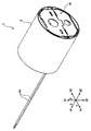
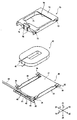
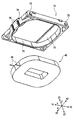
図1及び図2に示す振動アクチュエータ1は円柱状を呈し、その軸方向は、可動体の振動方向である第2方向Xに一致している。振動アクチュエータ1は、振動アクチュエータ1を手にした利用者に対し、可動体の第2方向Xの振動によって情報を報知し、例えばゲーム機の操作部材等として利用可能である。また、振動アクチュエータ1は、振動によって触覚を提示する触覚デバイスとしても利用可能である。
(overall structure)
The
振動アクチュエータ1は、振動アクチュエータ1の外形を規定する外ケース2と、外ケース2に収容されるアクチュエータ本体10とを備える。外ケース2は円筒状に形成されている。なお、外ケース2の形状は、振動アクチュエータ1の利用態様に応じて種々に変更できる。
The
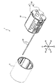
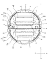
図3から図7に示すように、アクチュエータ本体10は、支持体11と、可動体12と、接続体13とを備える。そして、支持体11は、内ケース20と、ベースプレート30と、コイル40と、カバー70とを有し、可動体12は、永久磁石60と、ヨーク61とを有する。コイル40及び永久磁石60によって磁気駆動回路14が形成され、磁気駆動回路14は、可動体12を支持体11に対して第2方向Xに振動させる。接続体13は、弾性および粘弾性の少なくとも一方を備え、支持体11及び可動体12の双方に接する。接続体13が支持体11と可動体12との間に介在することにより、可動体12は、第2方向Xに振動可能に、支持体11に支持される。
As shown in FIGS. 3 to 7, the actuator
(支持体11の構成)
支持体11の内ケース20は筒状を呈し、その軸方向は、可動体12の振動方向である第2方向Xに一致している。内ケース20は、第1方向Zの一方側Z1に配置される第1ケース部材21と、他方側Z2に配置される第2ケース部材22とを有する。
(Structure of support 11)
The
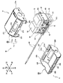
第1ケース部材21は、第1方向Zに対して略垂直に配置される第1平板部211と、第1平板部211の第3方向Yの両端から第1方向Zの他方側Z2に延びる一対の第1側板部212と、第1平板部211の第2方向Xの両端から第1方向Zの他方側Z2に延びる一対の第1蓋板部214とを有する。第1側板部212の端部には、矩形状の切り欠き部215と、一対の第1フランジ部213とが形成されおり、一対の第1フランジ部213は切り欠き部215の両側に隣設されている。
The
第2ケース部材22は、第1方向Zに対して略垂直に配置される第2平板部221と、第2平板部221の第3方向Yの両端から第1方向Zの一方側Z1に延びる一対の第2側板部222と、第2平板部221の第2方向Xの両端から第1方向Zの一方側Z1に延びる一対の第2蓋板部224とを有する。第2側板部222の端部には第2フランジ部223が形成されている。
The
第1ケース部材21の一対の第1フランジ部213と、第2ケース部材22の第2フランジ部223とが接合され、筒状の内ケース20が形成される。支持体11のベースプレート30、コイル40、及びカバー70と、可動体12の永久磁石60及びヨーク61と、接続体13とは、内ケース20に収容されている。
The pair of
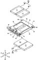
ベースプレート30は、銅、アルミニウム合金等の非磁性金属材料からなる。ベースプレート30は、コイル40が固定される矩形状の平板部31と、一対のフランジ部32と、一対の側板部33とを有する。一対のフランジ部32は、平板部31の一対の対辺から延設されており、一対の側板部33は、平板部31の他の一対の対辺に沿って立設されている。
The
フランジ部32は、切り欠き部215を通して内ケース20から突出し、内ケース20の第2フランジ部223に接合されている。ベースプレート30は、内ケース20の内側において、第3方向Yに対向する一対の第2側板部222に架け渡され、内ケース20の第1方向Zの中央部において、内ケース20の内側を第3方向Yに横断している。コイル40が固定されている平板部31は、内ケース20の第1平板部211及び第2平板部221と第1方向Zに対向しており、平板部31及びコイル40と第1平板部211との間、及び平板部31及びコイル40と第2平板部221との間には、隙間がおかれている。
The
一方のフランジ部32には、給電基板41が固定されている。給電基板41には、一対の第1ランド42(図6参照)と、一対の第2ランド43(図6参照)と、第1ランド42と第2ランド43とを接続している回路パターンとが設けられている。第1ランド42には、コイル40から引き出されたコイル線の端末部45(図6参照)が電気的に接続されており、第2ランド43には、リード線44の端末部が電気的に接続されている。コイル40は、リード線44及び給電基板41を介して給電される。
A
(可動体12の構成)
可動体12のヨーク61もまた筒状を呈する。ただし、ヨーク61の軸方向は、第3方向Yに一致している。ヨーク61は、第1方向Zの一方側Z1に配置される第1ヨーク62と、他方側Z2に配置される第2ヨーク63とを有する。第1ヨーク62及び第2ヨーク63は、鋼等の磁性材料からなる。
(Structure of movable body 12)
The
第1ヨーク62は平板状に形成されており、ベースプレート30に固定されたコイル40と内ケース20の第1平板部211との間で、第1方向Zに対して略垂直に配置されている。第2ヨーク63は、平板部631と、一対の側板部632とを有する。平板部631は、ベースプレート30と内ケース20の第2平板部221との間で、第1方向Zに対して略垂直に配置されている。側板部632は、平板部631の第2方向Xの両端端から第1方向Zの一方側Z1に延びており、ベースプレート30及びコイル40を第2方向Xに挟んで配置されている。そして、側板部632の端部が第1ヨーク62の第2方向Xの両端に接合され、筒状のヨーク61が形成される。ベースプレート30及びコイル40は、筒状のヨーク61の内側に配置されている。
The
第1ヨーク62は、内ケース20の第1平板部211と第1方向Zに対向しており、第2ヨーク63の平板部631は、内ケース20の第2平板部221と第1方向Zに対向している。第1ヨーク62と内ケース20の第1平板部211との間、及び第2ヨーク63の平板部631と内ケース20の第2平板部221との間には、接続体13がそれぞれ設けられている。ヨーク61は、これらの接続体13を介して内ケース20に支持されており、ベースプレート30、コイル40及びカバー70と非接触に配置されている。
The
第1ヨーク62には、第3方向Yの両端部から第1方向Zの他方側Z2に向けてL字形状に曲げられた第1規制部(規制部)621が設けられている。この第1規制部621は、落下等により衝撃を受けて、ヨーク61が相対的にコイル40側に移動した際に、コイル40を覆うカバー70の第1方向Zの一方側Z1の面に当接する。また、第2ヨーク63には、平板部631における第3方向Yの両端部から第1方向Zの一方側Z1に向けてL字形状に曲げられた第2規制部(規制部)633が設けられている。この第2規制部633は、落下等により衝撃を受けてヨーク61が相対的にコイル40側に移動した際に、コイル40を保持しているベースプレート30の第1方向Zの他方側Z2の面に当接する。
The
本例では、第1ヨーク62と接続体13との間にウェイト64が介装され、ウェイト64は第1ヨーク62に固定されている。また、第2ヨーク63の平板部631と接続体13との間にウェイト65が介装され、ウェイト65は第2ヨーク63の平板部631に固定されている。これらのウェイト64,65によって、可動体12の振動特性(例えば共振周波数)が適宜調整されている。ウェイト64、65の材料は特に限定されない。ウェイト64、65は、非磁性材料によって形成されてもよいが、磁束の漏洩を抑制する観点から、磁性材料によって形成されることが好ましい。
In this example, a
可動体12の永久磁石60は、第1磁石66と、第2磁石67とを有する。第1磁石66は、筒状のヨーク61の内側において、第1ヨーク62上に固定されており、コイル40と第1方向Zに対向している。第2磁石67は、筒状のヨーク61の内側において、第2ヨーク63の平板部631上に固定されており、コイル40と第1方向Zに対向している。
The
第1磁石66は、第2方向Xに隣り合って配置される一対の磁石661,662を有する。磁石661,662は、平板状に形成されており、厚さ方向に着磁されている。そして、磁石661,662それぞれのコイル40との対向面の磁極は、互いに逆の極性とされている。第2磁石67もまた、第2方向Xに隣り合って配置される一対の磁石671,672を有する。磁石671,672は、平板状に形成されており、厚さ方向に着磁されている。そして、磁石671,672それぞれのコイル40との対向面の磁極は、互いに逆の極性とされている。
The
そして、第2磁石67の一方の磁石671は、第1磁石66の一方の磁石661と第1方向Zに対向しており、磁石661,671それぞれのコイル40との対向面の磁極は、互いに逆の極性とされている。同様に、第2磁石67の他方の磁石672は、第1磁石66の他方の磁石662と第1方向Zに対向しており、磁石662,672それぞれのコイル40との対向面の磁極は、互いに逆の極性とされている。例えば、第1磁石66の一方の磁石661のコイル40との対向面がS極である場合に、第1磁石66の他方の磁石662のコイル40との対向面はN極である。そして、第2磁石67の一方の磁石671のコイル40との対向面はN極であり、第2磁石67の他方の磁石672のコイル40との対向面はS極である。
One
(磁気駆動回路14の構成)
コイル40は、コイル線を長円状に多数巻回してなる空芯のコイルである。コイル線は、第1磁石66の一方の磁石661と第2磁石67の一方の磁石671との間を第3方向Yの一方側Y1から他方側Y2に向けて横断し、且つ第1磁石66の他方の磁石662と第2磁石67の他方の磁石672との間を第3方向Yの他方側Y2から一方側Y1に向けて横断するように巻回されている。
(Structure of magnetic drive circuit 14)
The
コイル40は、カバー70を用いて、ベースプレート30の平板部31における所定位置に固定される。カバー70は、矩形板状に形成されており、ベースプレート30の平板部31に載置される。カバー70は、コイル40に対応する長円状に形成された凹部71を有し、コイル40は凹部71に嵌合する。カバー70が、ベースプレート30に位置決め固定されることにより、コイル40もまた、平板部31における所定位置に固定される。
The
カバー70をベースプレート30に固定するための固定手段として、カバー70を第2方向Xに挟むベースプレート30の一対の側板部33と、側板部33に接するカバー70の側面とに、係合部が設けられている。本例では、側板部33の係合部は、係合穴34によって構成されており、係合穴34は、側板部33の第3方向Yの両端部に形成されている。一方、カバー70の係合部は、係合穴34に嵌合する係合爪73によって構成されている。カバー70がベースプレート30の平板部31に載置されることにより、係合爪73が係合穴34に嵌合し、これにより、カバー70は、平板部31における所定位置に配置され、そして位置決めされた状態でベースプレート30に固定される。なお、係合穴がカバー70に設けられ、係合爪が側板部33に設けられてもよい。
As a fixing means for fixing the
凹部71の側壁部74には一対のスリット75が設けられており、また、凹部71の底壁部72には貫通穴76が設けられている。コイル40が凹部71に嵌合しており且つカバー70がベースプレート30に固定されている状態で、コイル線の端末部45は、スリット75を通してカバー70の外側に引き出され、給電基板41に電気的に接続される。また、コイル40の一部が貫通穴76を通して露出している。
A pair of
(動作)
交流電流がコイル40に供給される。コイル40への給電に伴い、第2方向Xのローレンツ力が支持体11側のコイル40に作用し、反力が可動体12側の第1磁石66及び第2磁石67に作用する。この第1磁石66及び第2磁石67に作用する反力に起因して、接続体13の第2方向Xのせん断変形を伴い、可動体12が第2方向Xに変位する。そして、ローレンツ力の作用方向が交流の半周期毎に逆転する。これにより、可動体12が第2方向Xに振動する。
(motion)
Alternating current is supplied to the
可動体12の振動特性は、ウェイト64、65の重量及び接続体13のせん断断面積によって調整され得る。例えば、ウェイト64、65の重量を大きくすることによって共振周波数を低周波数側にシフトさせることができ、逆に、ウェイト64、65の重量を小さくすることによって共振周波数を高周波数側にシフトさせることができる。また、接続体13のせん断断面積を小さくすることによって共振周波数を低周波数側にシフトさせることができ、接続体13のせん断断面積を大きくすることによって共振周波数を高周波数側にシフトさせることができる。
The vibration characteristics of the
ここで、可動体12及び接続体13を収納する支持体11の内ケース20は、第1方向Zの両側の端部に向かって内寸が小さくなっており、全体として円筒状に形成されている。具体的には、図8に示すように、内ケース20を構成する第1ケース部材21の第1側板部212は、第1平板部211の第3方向Yの両端から第1方向Zの他方側Z2に向かって外側に凸状に湾曲して設けられた第1湾曲部212aと、第1湾曲部212aの第1方向Zの他方側Z2の端部から第1方向の他方側Z2に向かって延びる第1鉛直部212bを有する。第1ケース部材21の第3方向Yの内寸L1は、第1平板部211側に向かって小さくなっている。第2ケース部材22の第2側板部222は、第2平板部221の第3方向Yの両端から第1方向Zの一方側Z1に向かって外側に凸状に湾曲して設けられた第2湾曲部222aと、第2湾曲部222aの第1方向Zの一方側Z1の端部から第1方向の一方側Z1に向かって延びる第2鉛直部222bを有する。第2ケース部材22の第3方向Yの内寸L2は、第2平板部221側に向かって小さくなっている。
Here, the
第1ヨーク62に固定されているウェイト64を厚くしてウェイト64の重量を大きくした場合に、ウェイト64と第1平板部211との間に介装される接続体13は、第1平板部211側に向かって小さくなる第1ケース部材21の内寸L1に制約され、第3方向Yの寸法が小さくなり、せん断断面積が小さくさなる。したがって、ウェイト64の重量増加に基づいて共振周波数が高周波数側にシフトし、さらに接続体13のせん断断面積の縮小に基づいて共振周波数が高周波数側にシフトし、内ケース20内部の限られたスペースにおいて効果的に振動特性が調整される。
When the
同様に、第2ヨーク63に固定されているウェイト65を厚くしてウェイト65の重量を大きくした場合に、ウェイト65と第2平板部221との間に介装される接続体13は、第2平板部221側に向かって小さくなる第2ケース部材22の内寸L2に制約され、第3方向Yの寸法が小さくなり、せん断断面積が小さくさなる。したがって、ウェイト65の重量増加に基づいて共振周波数が高周波数側にシフトし、さらに接続体13のせん断断面積の縮小に基づいて共振周波数が高周波数側にシフトし、内ケース20内部の限られたスペースにおいて効果的に振動特性が調整される。
Similarly, when the
また、コイル40を保持するホルダとしてのベースプレート30及びカバー70は、第3方向Yの内寸が相対的に大きい内ケース20の第1方向Zの中央部において、内ケース20の内側を第3方向Yに横断して固定されている。そして、ヨーク61の第1規制部621及び第2規制部633は、ベースプレート30及びカバー70の第3方向Yの両側の端部に対向して配置されている。これにより、第1規制部621及び第2規制部633と、ベースプレート30及びカバー70との接触面積を、内ケース20内部の限られたスペースにおいて確保でき、落下等により衝撃が作用した際には、可動体12の過度の移動を確実に規制できる。
Further, the
(他の実施の形態)
なお、上述した振動アクチュエータ1では、コイル40が支持体11に設けられ、永久磁石60が可動体12に設けられているが、コイル40が可動体12に設けられ、永久磁石60が支持体11に設けられてもよい。
(Other embodiments)
In the
以上、説明したとおり、本明細書に開示された振動アクチュエータは、可動体と、支持体と、弾性および粘弾性の少なくとも一方を備え、前記可動体と前記支持体とが対向する位置で前記可動体および前記支持体の双方に接するように配置された接続体と、前記可動体および前記支持体のうちの一方側部材に設けられた空芯のコイル、および前記コイルに対して第1方向の少なくとも一方側で対向するように前記可動体および前記支持体のうちの他方側部材に設けられた永久磁石を有し、前記可動体を前記支持体に対して前記第1方向と交差する第2方向に振動させる磁気駆動回路と、を備え、前記支持体は、前記可動体、前記接続体、及び前記磁気駆動回路を収納するケース体を有し、前記第1方向および前記第2方向と交差する第3方向における前記ケース体の内寸は、前記ケース体の前記第1方向の両側の端部側ほど小さく、前記可動体は、前記ケース体の前記第1方向の端部に対向するウェイトを有し、前記接続体は、前記ケース体の前記第1方向の端部と前記ウェイトとの間に配置されている。 As described above, the vibration actuator disclosed in the present specification includes a movable body, a support, and at least one of elastic and viscous elasticity, and the movable body and the support are movable at positions facing each other. A connection body arranged so as to be in contact with both the body and the support, an air-core coil provided on one side member of the movable body and the support, and a coil in the first direction with respect to the coil. A second unit having a permanent magnet provided on the movable body and the other side member of the support so as to face at least one side, and intersecting the movable body with respect to the support in the first direction. A magnetic drive circuit that vibrates in a direction is provided, and the support has a movable body, a connection body, and a case body that houses the magnetic drive circuit, and intersects the first direction and the second direction. The internal dimensions of the case body in the third direction are smaller toward both end portions of the case body in the first direction, and the movable body is a weight facing the end portions of the case body in the first direction. The connecting body is arranged between the end portion of the case body in the first direction and the weight.
また、本明細書に開示された振動アクチュエータは、前記ケース体が円筒状に形成されており、前記ケース体の軸方向は前記第2方向に一致している。 Further, in the vibration actuator disclosed in the present specification, the case body is formed in a cylindrical shape, and the axial direction of the case body coincides with the second direction.
また、本明細書に開示された振動アクチュエータは、前記ウェイトが、磁性材料からなる。 Further, in the vibration actuator disclosed in the present specification, the weight is made of a magnetic material.
また、本明細書に開示された振動アクチュエータは、前記可動体が、前記第1方向の変位に対して前記支持体と当接することにより、前記第1方向の移動を規制する規制部を有する。 Further, the vibration actuator disclosed in the present specification has a regulating unit that regulates the movement of the movable body in the first direction by contacting the movable body with the support in response to the displacement in the first direction.
また、本明細書に開示された振動アクチュエータは、前記支持体が、前記コイルおよび前記永久磁石の一方を保持するホルダを有し、前記ホルダは、前記ケース体の前記第1方向の中央部において、前記ケース体の内側を前記第3方向に横断しており、前記規制部は、前記ホルダの前記第3方向の両側の端部に当接する。 Further, in the vibration actuator disclosed in the present specification, the support has a holder that holds one of the coil and the permanent magnet, and the holder is located at the central portion of the case body in the first direction. The inside of the case body is crossed in the third direction, and the regulating portion abuts on both end portions of the holder in the third direction.
また、本明細書に開示された触覚デバイスは、可動体と、支持体と、弾性および粘弾性の少なくとも一方を備え、前記可動体と前記支持体とが対向する位置で前記可動体および前記支持体の双方に接するように配置された接続体と、前記可動体および前記支持体のうちの一方側部材に設けられた空芯のコイル、および前記コイルに対して第1方向の少なくとも一方側で対向するように前記可動体および前記支持体のうちの他方側部材に設けられた永久磁石を有し、前記可動体を前記支持体に対して前記第1方向と交差する第2方向に振動させる磁気駆動回路と、を備え、前記支持体は、前記可動体、前記接続体、及び前記磁気駆動回路を収納するケース体を有し、前記第1方向および前記第2方向と交差する第3方向における前記ケース体の内寸は、前記ケース体の前記第1方向の両側の端部側ほど小さく、前記可動体は、前記ケース体の前記第1方向の端部に対向するウェイトを有し、前記接続体は、前記ケース体の前記第1方向の端部と前記ウェイトとの間に配置されている。 Further, the tactile device disclosed in the present specification includes a movable body, a support, and at least one of elastic and viscoelastic, and the movable body and the support at a position where the movable body and the support face each other. An air-core coil provided on one side member of the movable body and the support, and at least one side in the first direction with respect to the coil, and a connecting body arranged so as to be in contact with both sides of the body. It has a permanent magnet provided on the movable body and the other side member of the support so as to face each other, and causes the movable body to vibrate with respect to the support in a second direction intersecting the first direction. The support includes a magnetic drive circuit, the support has a movable body, a connection body, and a case body for accommodating the magnetic drive circuit, and a third direction intersecting the first direction and the second direction. The inner dimension of the case body is smaller toward both ends of the case body in the first direction, and the movable body has a weight facing the ends of the case body in the first direction. The connecting body is arranged between the end portion of the case body in the first direction and the weight.
1 振動アクチュエータ
2 外ケース
10 アクチュエータ本体
11 支持体
12 可動体
13 接続体
14 磁気駆動回路
20 内ケース
21 第1ケース部材
211 第1平板部
212 第1側板部
213 第1フランジ部
214 第1蓋板部
215 切り欠き部
22 第2ケース部材
221 第2平板部
222 第2側板部
223 第2フランジ部
224 第2蓋板部
30 ベースプレート
31 平板部
32 フランジ部
33 側板部
34 係合穴
40 コイル
41 給電基板
44 リード線
60 永久磁石
61 ヨーク
62 第1ヨーク
621 第1規制部
63 第2ヨーク
631 平板部
632 側板部
633 第2規制部
64 ウェイト
65 ウェイト
66 第1磁石
661 磁石
662 磁石
67 第2磁石
671 磁石
672 磁石
70 カバー
71 凹部
73 係合爪
X 第2方向
Y 第3方向
Z 第1方向
1
Claims (6)
支持体と、
弾性および粘弾性の少なくとも一方を備え、前記可動体と前記支持体とが対向する位置で前記可動体および前記支持体の双方に接するように配置された接続体と、
前記可動体および前記支持体のうちの一方側部材に設けられた空芯のコイル、および前記コイルに対して第1方向の少なくとも一方側で対向するように前記可動体および前記支持体のうちの他方側部材に設けられた永久磁石を有し、前記可動体を前記支持体に対して前記第1方向と交差する第2方向に振動させる磁気駆動回路と、
を備え、
前記支持体は、前記可動体、前記接続体、及び前記磁気駆動回路を収納するケース体を有し、
前記第1方向および前記第2方向と交差する第3方向における前記ケース体の内寸は、前記ケース体の前記第1方向の両側の端部側ほど小さく、
前記可動体は、前記ケース体の前記第1方向の端部に対向するウェイトを有し、
前記接続体は、前記ケース体の前記第1方向の端部と前記ウェイトとの間に配置されている振動アクチュエータ。 Movable body and
With the support
A connector having at least one of elasticity and viscoelasticity and arranged so as to be in contact with both the movable body and the support at a position where the movable body and the support face each other.
An air-core coil provided on one side member of the movable body and the support, and of the movable body and the support so as to face the coil on at least one side in the first direction. A magnetic drive circuit having a permanent magnet provided on the other side member and vibrating the movable body in a second direction intersecting the first direction with respect to the support.
With
The support has a movable body, a connecting body, and a case body for accommodating the magnetic drive circuit.
The inner dimensions of the case body in the first direction and the third direction intersecting with the second direction are smaller toward both ends of the case body in the first direction.
The movable body has a weight facing the end portion of the case body in the first direction.
The connecting body is a vibration actuator arranged between the end portion of the case body in the first direction and the weight.
前記ケース体は円筒状に形成されており、
前記ケース体の軸方向は前記第2方向に一致している振動アクチュエータ。 The vibrating actuator according to claim 1.
The case body is formed in a cylindrical shape.
A vibrating actuator whose axial direction of the case body coincides with the second direction.
前記ウェイトは、磁性材料からなる振動アクチュエータ。 The vibrating actuator according to claim 1 or 2.
The weight is a vibration actuator made of a magnetic material.
前記可動体は、前記第1方向の変位に対して前記支持体と当接することにより、前記第1方向の移動を規制する規制部を有する振動アクチュエータ。 The vibrating actuator according to any one of claims 1 to 3.
The movable body is a vibration actuator having a regulating portion that regulates movement in the first direction by abutting against the support with respect to displacement in the first direction.
前記支持体は、前記コイルおよび前記永久磁石の一方を保持するホルダを有し、
前記ホルダは、前記ケース体の前記第1方向の中央部において、前記ケース体の内側を前記第3方向に横断しており、
前記規制部は、前記ホルダの前記第3方向の両側の端部に当接する振動アクチュエータ。 The vibrating actuator according to claim 4.
The support has a holder that holds one of the coil and the permanent magnet.
The holder crosses the inside of the case body in the third direction at the central portion of the case body in the first direction.
The restricting portion is a vibration actuator that abuts on both ends of the holder in the third direction.
支持体と、
弾性および粘弾性の少なくとも一方を備え、前記可動体と前記支持体とが対向する位置で前記可動体および前記支持体の双方に接するように配置された接続体と、
前記可動体および前記支持体のうちの一方側部材に設けられた空芯のコイル、および前記コイルに対して第1方向の少なくとも一方側で対向するように前記可動体および前記支持体のうちの他方側部材に設けられた永久磁石を有し、前記可動体を前記支持体に対して前記第1方向と交差する第2方向に振動させる磁気駆動回路と、
を備え、
前記支持体は、前記可動体、前記接続体、及び前記磁気駆動回路を収納するケース体を有し、
前記第1方向および前記第2方向と交差する第3方向における前記ケース体の内寸は、前記ケース体の前記第1方向の両側の端部側ほど小さく、
前記可動体は、前記ケース体の前記第1方向の端部に対向するウェイトを有し、
前記接続体は、前記ケース体の前記第1方向の端部と前記ウェイトとの間に配置されている触覚デバイス。
Movable body and
With the support
A connector having at least one of elasticity and viscoelasticity and arranged so as to be in contact with both the movable body and the support at a position where the movable body and the support face each other.
An air-core coil provided on one side member of the movable body and the support, and of the movable body and the support so as to face the coil on at least one side in the first direction. A magnetic drive circuit having a permanent magnet provided on the other side member and vibrating the movable body in a second direction intersecting the first direction with respect to the support.
With
The support has a movable body, a connecting body, and a case body for accommodating the magnetic drive circuit.
The inner dimensions of the case body in the first direction and the third direction intersecting with the second direction are smaller toward both ends of the case body in the first direction.
The movable body has a weight facing the end portion of the case body in the first direction.
The connection body is a tactile device arranged between the end portion of the case body in the first direction and the weight.
Priority Applications (1)
| Application Number | Priority Date | Filing Date | Title |
|---|---|---|---|
| JP2019088554A JP7460332B2 (en) | 2019-05-08 | 2019-05-08 | Vibration actuator and haptic device |
Applications Claiming Priority (1)
| Application Number | Priority Date | Filing Date | Title |
|---|---|---|---|
| JP2019088554A JP7460332B2 (en) | 2019-05-08 | 2019-05-08 | Vibration actuator and haptic device |
Publications (2)
| Publication Number | Publication Date |
|---|---|
| JP2020184843A true JP2020184843A (en) | 2020-11-12 |
| JP7460332B2 JP7460332B2 (en) | 2024-04-02 |
Family
ID=73045573
Family Applications (1)
| Application Number | Title | Priority Date | Filing Date |
|---|---|---|---|
| JP2019088554A Active JP7460332B2 (en) | 2019-05-08 | 2019-05-08 | Vibration actuator and haptic device |
Country Status (1)
| Country | Link |
|---|---|
| JP (1) | JP7460332B2 (en) |
Cited By (1)
| Publication number | Priority date | Publication date | Assignee | Title |
|---|---|---|---|---|
| JP2023009797A (en) * | 2021-07-08 | 2023-01-20 | 日本電産サンキョー株式会社 | actuator |
Citations (3)
| Publication number | Priority date | Publication date | Assignee | Title |
|---|---|---|---|---|
| WO2018030264A1 (en) * | 2016-08-09 | 2018-02-15 | 日本電産サンキョー株式会社 | Linear actuator |
| JP2019013089A (en) * | 2017-06-30 | 2019-01-24 | 日本電産サンキョー株式会社 | Actuator |
| JP2019012409A (en) * | 2017-06-30 | 2019-01-24 | 日本電産サンキョー株式会社 | Input device |
-
2019
- 2019-05-08 JP JP2019088554A patent/JP7460332B2/en active Active
Patent Citations (3)
| Publication number | Priority date | Publication date | Assignee | Title |
|---|---|---|---|---|
| WO2018030264A1 (en) * | 2016-08-09 | 2018-02-15 | 日本電産サンキョー株式会社 | Linear actuator |
| JP2019013089A (en) * | 2017-06-30 | 2019-01-24 | 日本電産サンキョー株式会社 | Actuator |
| JP2019012409A (en) * | 2017-06-30 | 2019-01-24 | 日本電産サンキョー株式会社 | Input device |
Cited By (2)
| Publication number | Priority date | Publication date | Assignee | Title |
|---|---|---|---|---|
| JP2023009797A (en) * | 2021-07-08 | 2023-01-20 | 日本電産サンキョー株式会社 | actuator |
| JP7798495B2 (en) | 2021-07-08 | 2026-01-14 | ニデックインスツルメンツ株式会社 | Actuator |
Also Published As
| Publication number | Publication date |
|---|---|
| JP7460332B2 (en) | 2024-04-02 |
Similar Documents
| Publication | Publication Date | Title |
|---|---|---|
| US11575302B2 (en) | Vibration actuator and mobile electronic apparatus including the same | |
| CN108787405B (en) | Vibration generating device | |
| TWI678057B (en) | Vibration generator | |
| US20110068640A1 (en) | Horizontal linear vibrator | |
| JP2011205870A (en) | Vibrating motor | |
| US12334792B2 (en) | Vibration actuator and electric apparatus | |
| US20190207501A1 (en) | Mover, vibration actuator, and electronic device | |
| US20110068641A1 (en) | Horizontal linear vibrator | |
| WO2023013761A1 (en) | Vibration actuator | |
| JP2023006575A (en) | Vibration actuator and electric apparatus | |
| JP2020184841A (en) | Vibration actuators and tactile devices | |
| US20190207499A1 (en) | Vibration actuator and electronic device | |
| JP2020184843A (en) | Vibration actuators and tactile devices | |
| JP7404515B2 (en) | Vibration generator | |
| CN114337180A (en) | Vibration actuator and electronic apparatus | |
| JP2018207553A (en) | Vibration motor | |
| JP2019106837A (en) | Linear vibration motor | |
| JP7444550B2 (en) | Vibration actuators and haptic devices | |
| JP7250610B2 (en) | Vibration actuators and haptic devices | |
| JP7250609B2 (en) | Vibration Actuator, Vibration Actuator Unit and Haptic Device | |
| JP2019193511A (en) | Linear vibration motor and electronic apparatus | |
| JP2022056733A (en) | Vibration actuator and electronic instrument | |
| JP2021052449A (en) | Actuator and tactile device | |
| CN205092754U (en) | Linear vibrating motor | |
| JP2019115196A (en) | Vibration power generator |
Legal Events
| Date | Code | Title | Description |
|---|---|---|---|
| A621 | Written request for application examination |
Free format text: JAPANESE INTERMEDIATE CODE: A621 Effective date: 20220414 |
|
| A977 | Report on retrieval |
Free format text: JAPANESE INTERMEDIATE CODE: A971007 Effective date: 20230309 |
|
| A131 | Notification of reasons for refusal |
Free format text: JAPANESE INTERMEDIATE CODE: A131 Effective date: 20230509 |
|
| A521 | Request for written amendment filed |
Free format text: JAPANESE INTERMEDIATE CODE: A523 Effective date: 20230621 |
|
| A02 | Decision of refusal |
Free format text: JAPANESE INTERMEDIATE CODE: A02 Effective date: 20231010 |
|
| A521 | Request for written amendment filed |
Free format text: JAPANESE INTERMEDIATE CODE: A523 Effective date: 20240104 |
|
| A911 | Transfer to examiner for re-examination before appeal (zenchi) |
Free format text: JAPANESE INTERMEDIATE CODE: A911 Effective date: 20240115 |
|
| TRDD | Decision of grant or rejection written | ||
| A01 | Written decision to grant a patent or to grant a registration (utility model) |
Free format text: JAPANESE INTERMEDIATE CODE: A01 Effective date: 20240227 |
|
| A61 | First payment of annual fees (during grant procedure) |
Free format text: JAPANESE INTERMEDIATE CODE: A61 Effective date: 20240321 |
|
| R150 | Certificate of patent or registration of utility model |
Ref document number: 7460332 Country of ref document: JP Free format text: JAPANESE INTERMEDIATE CODE: R150 |