JP2020184841A - Vibration actuators and tactile devices - Google Patents
Vibration actuators and tactile devices Download PDFInfo
- Publication number
- JP2020184841A JP2020184841A JP2019088550A JP2019088550A JP2020184841A JP 2020184841 A JP2020184841 A JP 2020184841A JP 2019088550 A JP2019088550 A JP 2019088550A JP 2019088550 A JP2019088550 A JP 2019088550A JP 2020184841 A JP2020184841 A JP 2020184841A
- Authority
- JP
- Japan
- Prior art keywords
- coil
- movable body
- support
- base plate
- permanent magnet
- Prior art date
- Legal status (The legal status is an assumption and is not a legal conclusion. Google has not performed a legal analysis and makes no representation as to the accuracy of the status listed.)
- Pending
Links
Images
Landscapes
- Apparatuses For Generation Of Mechanical Vibrations (AREA)
- Reciprocating, Oscillating Or Vibrating Motors (AREA)
Abstract
【課題】振動アクチュエータの温度変化に対する耐久性を高める。【解決手段】振動アクチュエータ1は、可動体12と、支持体11と、接続体13と、支持体11に設けられた空芯のコイル40、およびコイル40に第1方向Zに対向するように可動体12に設けられた永久磁石60を有し、可動体12を支持体11に対して第2方向Xに振動させる磁気駆動回路14と、コイル40と電気的に接続された給電基板41と、を備え、コイル40が設けられた支持体11は、非磁性金属材料からなるベースプレート30を有し、コイル40及び給電基板41は、ベースプレート30に接合されている。【選択図】図3An object of the present invention is to improve the durability of a vibration actuator against temperature changes. A vibration actuator 1 includes a movable body 12, a support 11, a connection body 13, an air-core coil 40 provided on the support 11, and a coil 40 facing the coil 40 in a first direction Z. a magnetic drive circuit 14 having a permanent magnet 60 provided on the movable body 12 and vibrating the movable body 12 in the second direction X with respect to the support body 11; and a power supply board 41 electrically connected to the coil 40. The support body 11 includes a coil 40 and has a base plate 30 made of a non-magnetic metal material, and the coil 40 and the power supply board 41 are joined to the base plate 30. [Selection diagram] Figure 3
Description
本発明は、可動体を振動させる振動アクチュエータ及び触覚デバイスに関するものである。 The present invention relates to a vibrating actuator and a tactile device that vibrate a movable body.
情報を振動によって報知するデバイスとして、永久磁石を有する支持体と、永久磁石と対向するコイルを有する可動体とを備え、コイルに交流電流を流し、コイルに作用するローレンツ力を駆動力として、可動体を振動させるアクチュエータが知られている(特許文献1参照)。 As a device that notifies information by vibration, a support having a permanent magnet and a movable body having a coil facing the permanent magnet are provided, an alternating current is passed through the coil, and the Lorentz force acting on the coil is used as a driving force to move. Actuators that vibrate the body are known (see Patent Document 1).
特許文献1に記載されたアクチュエータでは、支持体及び可動体はケースに収納されており、ケースには、コイルと電気的に接続される給電基板が固定されている。ケースは、互いにネジ止めされる2つのケース部材からなり、一方のケース部材には、ネジ止めのためのボスが複数設けられている。この種のケース部材は、典型的には樹脂材料からなる。 In the actuator described in Patent Document 1, a support and a movable body are housed in a case, and a power feeding board electrically connected to a coil is fixed to the case. The case is composed of two case members that are screwed to each other, and one case member is provided with a plurality of bosses for screwing. This type of case member is typically made of a resin material.
アクチュエータは、動作に伴って昇温する。そして、コイル線は銅等の金属材料からなり、金属材料の線膨張係数と樹脂材料の線膨張係数とは大きく異なる。このため、温度変化に対して、コイル線とケース部材との間に膨張量又は収縮量の差が生じ得る。給電基板は樹脂材料からなるケース部材に固定されており、コイル線とケース部材との間の膨張量又は収縮量の差に起因して、給電基板に接続されるコイルの引き出し線が断線する虞がある。 The actuator heats up as it operates. The coil wire is made of a metal material such as copper, and the coefficient of linear expansion of the metal material and the coefficient of linear expansion of the resin material are significantly different. Therefore, a difference in the amount of expansion or contraction may occur between the coil wire and the case member with respect to the temperature change. The power supply board is fixed to a case member made of a resin material, and there is a risk that the lead wire of the coil connected to the power supply board may be broken due to the difference in the amount of expansion or contraction between the coil wire and the case member. There is.
本発明は、上述した事情に鑑みなされたものであり、温度変化に対する耐久性を高めることができる振動アクチュエータ及び触覚デバイスを提供することを目的とする。 The present invention has been made in view of the above circumstances, and an object of the present invention is to provide a vibration actuator and a tactile device capable of increasing durability against temperature changes.
本発明の一態様の振動アクチュエータは、可動体と、支持体と、弾性および粘弾性の少なくとも一方を備え、前記可動体と前記支持体とが対向する位置で前記可動体および前記支持体の双方に接するように配置された接続体と、前記可動体および前記支持体のうちの一方側部材に設けられた空芯のコイル、および前記コイルに対して第1方向の少なくとも一方側で対向するように前記可動体および前記支持体のうちの他方側部材に設けられた永久磁石を有し、前記可動体を前記支持体に対して前記第1方向と交差する第2方向に振動させる磁気駆動回路と、前記コイルと電気的に接続された給電基板と、を備え、前記コイルが設けられた前記可動体および前記支持体のうちの一方側部材は、非磁性金属材料からなるベースプレートを有し、前記コイル及び前記給電基板は、前記ベースプレートに接合されている。 The vibrating actuator of one aspect of the present invention includes a movable body, a support, and at least one of elastic and viscoelastic, and both the movable body and the support at a position where the movable body and the support face each other. An air-core coil provided on one side member of the movable body and the support, and the coil arranged so as to be in contact with the coil, so as to face at least one side in the first direction. A magnetic drive circuit having a permanent magnet provided on the other side member of the movable body and the support and vibrating the movable body with respect to the support in a second direction intersecting the first direction. And a power supply board electrically connected to the coil, and one side member of the movable body and the support provided with the coil has a base plate made of a non-magnetic metal material. The coil and the power feeding board are joined to the base plate.
また、本発明の一態様の触覚デバイスは、可動体と、支持体と、弾性および粘弾性の少なくとも一方を備え、前記可動体と前記支持体とが対向する位置で前記可動体および前記支持体の双方に接するように配置された接続体と、前記可動体および前記支持体のうちの一方側部材に設けられた空芯のコイル、および前記コイルに対して第1方向の少なくとも一方側で対向するように前記可動体および前記支持体のうちの他方側部材に設けられた永久磁石を有し、前記可動体を前記支持体に対して前記第1方向と交差する第2方向に振動させる磁気駆動回路と、前記コイルと電気的に接続された給電基板と、を備え、前記コイルが設けられた前記可動体および前記支持体のうちの一方側部材は、非磁性金属材料からなるベースプレートを有し、前記コイル及び前記給電基板は、前記ベースプレートに接合されている。 Further, the tactile device of one aspect of the present invention includes a movable body, a support, and at least one of elastic and viscoelastic, and the movable body and the support are at positions where the movable body and the support face each other. An air-core coil provided on one side member of the movable body and the support body, and an air-core coil provided so as to be in contact with both of the above coils, and facing the coil on at least one side in the first direction. A magnet that has a permanent magnet provided on the other side member of the movable body and the support so as to vibrate the movable body in a second direction intersecting the first direction with respect to the support. A drive circuit, a power supply board electrically connected to the coil, and one side member of the movable body and the support provided with the coil have a base plate made of a non-magnetic metal material. The coil and the power feeding board are joined to the base plate.
本発明によれば、温度変化に対する耐久性を高めることができる振動アクチュエータ及び触覚デバイスを提供できる。 According to the present invention, it is possible to provide a vibrating actuator and a tactile device capable of increasing durability against temperature changes.
以下に、図面を参照して、本発明の実施形態を説明する。以下の説明において、可動体の振動方向(第2方向)をXとし、第2方向Xの一方側をX1とし、他方側をX2とする。また、第2方向Xと交差する第1方向をZとし、第1方向Zおよび第2方向Xと交差する第3方向をYとする。 Hereinafter, embodiments of the present invention will be described with reference to the drawings. In the following description, the vibration direction (second direction) of the movable body is X, one side of the second direction X is X1, and the other side is X2. Further, let Z be the first direction that intersects the second direction X, and let Y be the third direction that intersects the first direction Z and the second direction X.
(全体構成)
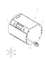
図1に示す振動アクチュエータ1は円柱状を呈し、その軸方向は、可動体の振動方向である第2方向Xに一致している。振動アクチュエータ1は、振動アクチュエータ1を手にした利用者に対し、可動体の第2方向Xの振動によって情報を報知し、例えばゲーム機の操作部材等として利用可能である。また、振動アクチュエータ1は、振動によって触覚を提示する触覚デバイスとしても利用可能である。
(overall structure)
The vibration actuator 1 shown in FIG. 1 has a columnar shape, and its axial direction coincides with the second direction X, which is the vibration direction of the movable body. The vibration actuator 1 notifies the user who holds the vibration actuator 1 of information by vibration in the second direction X of the movable body, and can be used as, for example, an operating member of a game machine. The vibration actuator 1 can also be used as a tactile device that presents a tactile sensation by vibration.
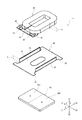
図2に示すように、振動アクチュエータ1は、振動アクチュエータ1の外形を規定する外ケース2と、外ケース2に収容されるアクチュエータ本体10とを備える。外ケース2は、円筒状の外ケース本体3と、外ケース本体3の軸方向両側の端部を塞ぐ蓋板4,5とを有する。外ケース本体3の外周壁は部分的に切り欠かれており、アクチュエータ本体10は、外ケース本体3の外周壁の切欠きを通して、部分的に露出している。なお、外ケース2の形状は、振動アクチュエータ1の利用態様に応じて種々に変更できる。
As shown in FIG. 2, the vibration actuator 1 includes an
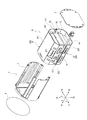
アクチュエータ本体10は、支持体11と、可動体12と、接続体13とを備える。そして、支持体11は、内ケース20と、ベースプレート30と、コイル40とを有し、可動体12は、永久磁石60と、ヨーク61とを有する。コイル40及び永久磁石60によって磁気駆動回路14が形成され、磁気駆動回路14は、可動体12を支持体11に対して第2方向Xに振動させる。接続体13は、弾性および粘弾性の少なくとも一方を備え、支持体11及び可動体12の双方に接する。接続体13が支持体11と可動体12との間に介在することにより、可動体12は、第2方向Xに振動可能に、支持体11に支持される。
The
(支持体11の構成)
図3から図5に示すように、支持体11の内ケース20は角筒状を呈し、その軸方向は、可動体12の振動方向である第2方向Xに一致している。内ケース20は、第1方向Zの一方側Z1に配置される第1ケース部材21と、他方側Z2に配置される第2ケース部材22とを有する。
(Structure of support 11)
As shown in FIGS. 3 to 5, the
第1ケース部材21は、第1方向Zに対して略垂直に配置される第1平板部211と、第1平板部211の第3方向Yの両端から第1方向Zの他方側Z2に延びる一対の第1側板部212とを有する。第1側板部212の端部には、矩形状の切り欠き部214と、一対の第1フランジ部213とが形成されおり、一対の第1フランジ部213は切り欠き部214の両側に隣設されている。
The
第2ケース部材22は、第1方向Zに対して略垂直に配置される第2平板部221と、第2平板部221の第3方向Yの両端から第1方向Zの一方側Z1に延びる一対の第2側板部222とを有する。第2側板部222の端部には第2フランジ部223が形成されている。
The
第1ケース部材21の一対の第1フランジ部213と、第2ケース部材22の第2フランジ部223とが接合され、筒状の内ケース20が形成される。支持体11のベースプレート30及びコイル40と、可動体12の永久磁石60及びヨーク61と、接続体13とは、内ケース20に収容されている。
The pair of
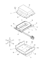
ベースプレート30は、銅、アルミニウム合金等の非磁性金属材料からなる。ベースプレート30は、コイル40が固定される矩形状の平板部31と、一対のフランジ部32と、一対の側板部33とを有する。一対のフランジ部32は、平板部31の一対の対辺から延設されており、一対の側板部33は、平板部31の他の一対の対辺に沿って立設されている。
The
フランジ部32は、切り欠き部214を通して内ケース20から突出し、内ケース20の第2フランジ部223に接合されている。したがって、ベースプレート30は、内ケース20の内側において、第3方向Yに対向する一対の第2側板部222に架け渡されている。コイル40が固定されている平板部31は、内ケース20の第1平板部211及び第2平板部221と第1方向Zに対向しており、平板部31及びコイル40と第1平板部211との間、及び平板部31及びコイル40と第2平板部221との間には、隙間がおかれている。側板部33は、平板部31に固定されたコイル40を第2方向Xに挟んで対向している。側板部33の高さHは、コイル40の厚さT以上である。
The
一方のフランジ部32には、給電基板41が固定されている。給電基板41には、一対の第1ランド42と、一対の第2ランド43と、第1ランド42と第2ランド43とを接続している回路パターンとが設けられている。第1ランド42には、コイル40から引き出されたコイル線の端末部が電気的に接続されており、第2ランド43には、リード線44の端末部が電気的に接続されている。リード線44は、内ケース20と外ケース本体3との間の隙間を通って第2方向Xの他方側X2に向けて延ばされ、蓋板5を貫いて外ケース2から引き出されている。コイル40は、リード線44及び給電基板41を介して給電される。
A
(可動体12の構成)
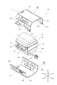
図3から図5に示すように、可動体12のヨーク61もまた角筒状を呈する。ただし、ヨーク61の軸方向は、第3方向Yに一致している。ヨーク61は、第1方向Zの一方側Z1に配置される第1ヨーク62と、他方側Z2に配置される第2ヨーク63とを有する。第1ヨーク62及び第2ヨーク63は、鋼等の磁性材料からなる。
(Structure of movable body 12)
As shown in FIGS. 3 to 5, the
第1ヨーク62は平板状に形成されており、ベースプレート30及びコイル40と内ケース20の第1平板部211との間で、第1方向Zに対して略垂直に配置されている。第2ヨーク63は、平板部631と、一対の側板部632とを有する。平板部631は、ベースプレート30及びコイル40と内ケース20の第2平板部221との間で、第1方向Zに対して略垂直に配置されている。側板部632は、平板部631の第2方向Xの両端端から第1方向Zの一方側Z1に延びており、ベースプレート30及びコイル40を第2方向Xに挟んで配置されている。そして、側板部632の端部が第1ヨーク62の第2方向Xの両端に接合され、筒状のヨーク61が形成される。ベースプレート30及びコイル40は、筒状のヨーク61の内側に配置されている。
The
第1ヨーク62は、内ケース20の第1平板部211と第1方向Zに対向しており、第2ヨーク63の平板部631は、内ケース20の第2平板部221と第1方向Zに対向している。第1ヨーク62と内ケース20の第1平板部211との間、及び第2ヨーク63の平板部631と内ケース20の第2平板部221との間には、接続体13がそれぞれ設けられている。ヨーク61は、これらの接続体13を介して内ケース20に支持されており、ベースプレート30及びコイル40と非接触に配置されている。
The
なお、本例では、第1ヨーク62と接続体13との間にウェイト64が介装され、ウェイト64は第1ヨーク62に固定されている。また、第2ヨーク63の平板部631と接続体13との間にウェイト65が介装され、ウェイト65は第2ヨーク63の平板部631に固定されている。これらのウェイト64,65によって、可動体12の振動特性(例えば共振周波数)が適宜調整されている。
In this example, a
可動体12の永久磁石60は、筒状のヨーク61の内側において、第2ヨーク63の平板部631上に固定されており、コイル40と第1方向Zに対向している。永久磁石60は、平板状に形成されており、永久磁石60の厚さ方向両側の表面は、第2方向Xに2極に着磁されている。すなわち、永久磁石60を第2方向に並ぶ第1領域601と第2領域602とに分け、例えば、第1領域601の第1方向Zの一方側Z1の表面がS極である場合に、第2領域602の第1方向Zの一方側Z1の表面はN極である。そして、第1領域601の他方側Z2の表面はN極であり、第2領域602の他方側Z2の表面はS極である。
The
(磁気駆動回路14の構成)
コイル40は、コイル線を長円状に多数巻回してなる空芯のコイルである。コイル線は、永久磁石60の第1領域601を第3方向Yの一方側Y1から他方側Y2に向けて横断し、且つ第2領域602を第3方向Yの他方側Y2から一方側Y1に向けて横断するように巻回されている。
(Structure of magnetic drive circuit 14)
The
(動作)
交流電流がコイル40に供給される。コイル40への給電に伴い、第2方向Xのローレンツ力が支持体11側のコイル40に作用し、反力が可動体12側の永久磁石60に作用する。この永久磁石60に作用する反力に起因して、接続体13の第2方向Xのせん断変形を伴い、可動体12が第2方向Xに変位する。そして、ローレンツ力の作用方向が交流の半周期毎に逆転する。これにより、可動体12が第2方向Xに振動する。
(motion)
Alternating current is supplied to the
(作用・効果)
コイル40への給電に伴い、コイル40が発熱する。また、コイル40に生じた熱はベースプレート30に伝わり、ベースプレート30の温度が上昇する。ここで、コイル40は銅等の金属材料からなり、ベースプレート30もまた金属材料からなる。そして、コイル40から引き出されたコイル線の端末部が電気的に接続される給電基板41がベースプレート30に固定されている。これにより、コイル40から引き出されたコイル線の端末部の膨張量と、ベースプレート30におけるコイル40と給電基板41との間の領域との膨張量との差が軽減され、コイル線の断線が抑制される。
(Action / effect)
The
内ケース20(第1ケース部材21及び第2ケース部材22)の材料は、樹脂材料でもよいが、好ましくは熱伝導率の高い金属材料であり、例えばアルミニウム合金である。これにより、コイル40に生じた熱をベースプレート30から内ケース20に速やかに導いてコイル40及びベースプレート30の昇温を抑制でき、コイル線の断線を一層抑制できる。さらに、本例では、外ケース本体3の外周壁の切欠きを通して、内ケース20が部分的に露出し、内ケース20による放熱作用が高められているので、コイル40及びベースプレート30の昇温を一層抑制できる。
The material of the inner case 20 (
振動アクチュエータ1の通常の使用において、ベースプレート30及びコイル40と、ベースプレート30及びコイル40を取り囲むヨーク61とは非接触に保たれるが、振動アクチュエータ1に過大な衝撃が作用した場合に、ベースプレート30及びコイル40とヨーク61とが接触する場合がある。この場合に、ベースプレート30においてコイル40の周囲に配置される側板部33の高さHがコイル40の厚みT以上であるので、コイル40とヨーク61との接触を回避でき、コイル線の断線を一層抑制できる。好ましくは、一対の側板部33がコイル40を挟んで対向して配置され、より好ましくは、一対の側板部33は、可動体12の振動方向である第2方向Xに挟んで対向して配置される。これにより、コイル40とヨーク61との接触をより確実に回避できる。
In normal use of the vibrating actuator 1, the
また、永久磁石60が第2方向Xに2極着磁された磁石であり、磁気駆動回路14を構成する磁石が一つで足りるので、磁石をヨーク61に固定する作業が容易である。
Further, since the
(他の実施の形態)
なお、第2方向Xに2極着磁された永久磁石60に替えて、コイル40に対し第1方向Zの同じ側で第2方向Xに隣り合って配置される一対の永久磁石が用いられてもよい。この場合に、一対の永久磁石それぞれのコイル40との対向面の磁極は、互いに逆の極性とされる。すなわち、永久磁石60の第1領域601及び第2領域602が、領域毎に個別の永久磁石に置換されてもよい。永久磁石60の第1領域601と第2領域602との境界近傍では相対的に磁界強度が低下するが、一対の永久磁石が用いられることにより、一対の永久磁石の間の磁界強度を高めることができる。これにより、効率よく可動体12を振動させることができる。
(Other embodiments)
Instead of the
なお、上述した振動アクチュエータ1では、コイル40が支持体11に設けられ、永久磁石60が可動体12に設けられているが、コイル40が可動体12に設けられ、永久磁石60が支持体11に設けられてもよい。
In the vibration actuator 1 described above, the
以上、説明したとおり、本明細書に開示された振動アクチュエータは、可動体と、支持体と、弾性および粘弾性の少なくとも一方を備え、前記可動体と前記支持体とが対向する位置で前記可動体および前記支持体の双方に接するように配置された接続体と、前記可動体および前記支持体のうちの一方側部材に設けられた空芯のコイル、および前記コイルに対して第1方向の少なくとも一方側で対向するように前記可動体および前記支持体のうちの他方側部材に設けられた永久磁石を有し、前記可動体を前記支持体に対して前記第1方向と交差する第2方向に振動させる磁気駆動回路と、前記コイルと電気的に接続された給電基板と、を備え、前記コイルが設けられた前記可動体および前記支持体のうちの一方側部材は、非磁性金属材料からなるベースプレートを有し、前記コイル及び前記給電基板は、前記ベースプレートに接合されている。 As described above, the vibration actuator disclosed in the present specification includes a movable body, a support, and at least one of elastic and viscoelastic, and the movable body and the support are movable at positions facing each other. A connection body arranged so as to be in contact with both the body and the support, an air-core coil provided on one side member of the movable body and the support, and a coil in the first direction with respect to the coil. A second unit having a permanent magnet provided on the movable body and the other side member of the support so as to face at least one side, and intersecting the movable body with respect to the support in the first direction. A magnetic drive circuit that vibrates in a direction and a power supply board that is electrically connected to the coil are provided, and one side member of the movable body and the support provided with the coil is made of a non-magnetic metal material. It has a base plate made of, and the coil and the power feeding board are joined to the base plate.
また、本明細書に開示された振動アクチュエータは、前記ベースプレートが、前記コイルが設置される平板部と、前記平板部に立設され、前記コイルの周囲に配置される一つ以上の側板部と、を有し、前記側板部の高さは、前記コイルの厚み以上である。 Further, in the vibration actuator disclosed in the present specification, the base plate includes a flat plate portion on which the coil is installed and one or more side plate portions erected on the flat plate portion and arranged around the coil. , And the height of the side plate portion is equal to or greater than the thickness of the coil.
また、本明細書に開示された振動アクチュエータは、前記ベースプレートが、前記コイルを挟んで対向して配置される一対の前記側板部を有する。 Further, the vibration actuator disclosed in the present specification has a pair of side plate portions in which the base plate is arranged so as to face each other with the coil in between.
また、本明細書に開示された振動アクチュエータは、前記一対の側板部が、前記コイルを前記第2方向に挟んで対向して配置されている。 Further, in the vibration actuator disclosed in the present specification, the pair of side plate portions are arranged so as to face each other with the coil sandwiched in the second direction.
また、本明細書に開示された振動アクチュエータは、前記永久磁石が、前記第2方向に2極着磁された磁石である。 Further, the vibration actuator disclosed in the present specification is a magnet in which the permanent magnet is magnetized in two poles in the second direction.
また、本明細書に開示された振動アクチュエータは、前記永久磁石が、前記コイルに対して前記第1方向の同じ側で前記第2方向に隣り合って配置される一対の磁石からなり、前記一対の磁石それぞれの前記コイルとの対向面の磁極は、互いに逆の極性である。 Further, the vibration actuator disclosed in the present specification comprises a pair of magnets in which the permanent magnets are arranged adjacent to each other in the second direction on the same side of the first direction with respect to the coil. The magnetic poles of each of the magnets facing the coil have opposite polarities.
また、本明細書に開示された触覚デバイスは、可動体と、支持体と、弾性および粘弾性の少なくとも一方を備え、前記可動体と前記支持体とが対向する位置で前記可動体および前記支持体の双方に接するように配置された接続体と、前記可動体および前記支持体のうちの一方側部材に設けられた空芯のコイル、および前記コイルに対して第1方向の少なくとも一方側で対向するように前記可動体および前記支持体のうちの他方側部材に設けられた永久磁石を有し、前記可動体を前記支持体に対して前記第1方向と交差する第2方向に振動させる磁気駆動回路と、前記コイルと電気的に接続された給電基板と、を備え、前記コイルが設けられた前記可動体および前記支持体のうちの一方側部材は、非磁性金属材料からなるベースプレートを有し、前記コイル及び前記給電基板は、前記ベースプレートに接合されている。 Further, the tactile device disclosed in the present specification includes a movable body, a support, and at least one of elastic and viscoelastic, and the movable body and the support at a position where the movable body and the support face each other. A connecting body arranged so as to be in contact with both bodies, an air-core coil provided on one side member of the movable body and the support, and at least one side in the first direction with respect to the coil. It has a permanent magnet provided on the movable body and the other side member of the support so as to face each other, and causes the movable body to vibrate with respect to the support in a second direction intersecting the first direction. A base plate made of a non-magnetic metal material is provided as a magnetic drive circuit, a power supply board electrically connected to the coil, and one side member of the movable body and the support provided with the coil. The coil and the power supply substrate are joined to the base plate.
1 振動アクチュエータ
2 外ケース
3 外ケース本体
4 蓋板
5 蓋板
10 アクチュエータ本体
11 支持体
12 可動体
13 接続体
14 磁気駆動回路
20 内ケース
21 第1ケース部材
22 第2ケース部材
30 ベースプレート
31 平板部
32 フランジ部
33 側板部
40 コイル
41 給電基板
42 第1ランド
43 第2ランド
44 リード線
60 永久磁石
61 ヨーク
62 第1ヨーク
63 第2ヨーク
64 ウェイト
65 ウェイト
211 第1平板部
212 第1側板部
213 第1フランジ部
214 切り欠き部
221 第2平板部
222 第2側板部
223 第2フランジ部
601 第1領域
602 第2領域
631 平板部
632 側板部
X 第2方向
Y 第3方向
Z 第1方向
1
Claims (7)
支持体と、
弾性および粘弾性の少なくとも一方を備え、前記可動体と前記支持体とが対向する位置で前記可動体および前記支持体の双方に接するように配置された接続体と、
前記可動体および前記支持体のうちの一方側部材に設けられた空芯のコイル、および前記コイルに対して第1方向の少なくとも一方側で対向するように前記可動体および前記支持体のうちの他方側部材に設けられた永久磁石を有し、前記可動体を前記支持体に対して前記第1方向と交差する第2方向に振動させる磁気駆動回路と、
前記コイルと電気的に接続された給電基板と、
を備え、
前記コイルが設けられた前記可動体および前記支持体のうちの一方側部材は、非磁性金属材料からなるベースプレートを有し、
前記コイル及び前記給電基板は、前記ベースプレートに固定されている振動アクチュエータ。 Movable body and
With the support
A connector having at least one of elasticity and viscoelasticity and arranged so as to be in contact with both the movable body and the support at a position where the movable body and the support face each other.
An air-core coil provided on one side member of the movable body and the support, and of the movable body and the support so as to face the coil on at least one side in the first direction. A magnetic drive circuit having a permanent magnet provided on the other side member and vibrating the movable body in a second direction intersecting the first direction with respect to the support.
A power supply board electrically connected to the coil and
With
One side member of the movable body and the support provided with the coil has a base plate made of a non-magnetic metal material.
The coil and the power feeding board are vibration actuators fixed to the base plate.
前記ベースプレートは、
前記コイルが設置される平板部と、
前記平板部に立設され、前記コイルの周囲に配置される一つ以上の側板部と、
を有し、
前記側板部の高さは、前記コイルの厚み以上である振動アクチュエータ。 The vibrating actuator according to claim 1.
The base plate
The flat plate where the coil is installed and
One or more side plate portions erected on the flat plate portion and arranged around the coil, and
Have,
A vibration actuator in which the height of the side plate portion is equal to or greater than the thickness of the coil.
前記ベースプレートは、前記コイルを挟んで対向して配置される一対の前記側板部を有する振動アクチュエータ。 The vibrating actuator according to claim 2.
The base plate is a vibration actuator having a pair of side plate portions arranged so as to face each other with the coil interposed therebetween.
前記一対の側板部は、前記コイルを前記第2方向に挟んで対向して配置されている振動アクチュエータ。 The vibrating actuator according to claim 3.
The pair of side plate portions are vibration actuators arranged so as to face each other with the coil sandwiched in the second direction.
前記永久磁石は、前記第2方向に2極着磁された磁石である振動アクチュエータ。 The vibrating actuator according to any one of claims 1 to 4.
The permanent magnet is a vibration actuator which is a magnet magnetized with two poles in the second direction.
前記永久磁石は、前記コイルに対して前記第1方向の同じ側で前記第2方向に隣り合って配置される一対の磁石からなり、
前記一対の磁石それぞれの前記コイルとの対向面の磁極は、互いに逆の極性である振動アクチュエータ。 The vibrating actuator according to any one of claims 1 to 4.
The permanent magnet comprises a pair of magnets arranged adjacent to each other in the second direction on the same side of the first direction with respect to the coil.
A vibrating actuator in which the magnetic poles of the pair of magnets facing each other with the coil have opposite polarities.
支持体と、
弾性および粘弾性の少なくとも一方を備え、前記可動体と前記支持体とが対向する位置で前記可動体および前記支持体の双方に接するように配置された接続体と、
前記可動体および前記支持体のうちの一方側部材に設けられた空芯のコイル、および前記コイルに対して第1方向の少なくとも一方側で対向するように前記可動体および前記支持体のうちの他方側部材に設けられた永久磁石を有し、前記可動体を前記支持体に対して前記第1方向と交差する第2方向に振動させる磁気駆動回路と、
前記コイルと電気的に接続された給電基板と、
を備え、
前記コイルが設けられた前記可動体および前記支持体のうちの一方側部材は、非磁性金属材料からなるベースプレートを有し、
前記コイル及び前記給電基板は、前記ベースプレートに固定されている触覚デバイス。 Movable body and
With the support
A connector having at least one of elasticity and viscoelasticity and arranged so as to be in contact with both the movable body and the support at a position where the movable body and the support face each other.
An air-core coil provided on one side member of the movable body and the support, and of the movable body and the support so as to face the coil on at least one side in the first direction. A magnetic drive circuit having a permanent magnet provided on the other side member and vibrating the movable body in a second direction intersecting the first direction with respect to the support.
A power supply board electrically connected to the coil and
With
One side member of the movable body and the support provided with the coil has a base plate made of a non-magnetic metal material.
The coil and the power feeding board are tactile devices fixed to the base plate.
Priority Applications (1)
| Application Number | Priority Date | Filing Date | Title |
|---|---|---|---|
| JP2019088550A JP2020184841A (en) | 2019-05-08 | 2019-05-08 | Vibration actuators and tactile devices |
Applications Claiming Priority (1)
| Application Number | Priority Date | Filing Date | Title |
|---|---|---|---|
| JP2019088550A JP2020184841A (en) | 2019-05-08 | 2019-05-08 | Vibration actuators and tactile devices |
Publications (1)
| Publication Number | Publication Date |
|---|---|
| JP2020184841A true JP2020184841A (en) | 2020-11-12 |
Family
ID=73045530
Family Applications (1)
| Application Number | Title | Priority Date | Filing Date |
|---|---|---|---|
| JP2019088550A Pending JP2020184841A (en) | 2019-05-08 | 2019-05-08 | Vibration actuators and tactile devices |
Country Status (1)
| Country | Link |
|---|---|
| JP (1) | JP2020184841A (en) |
Cited By (3)
| Publication number | Priority date | Publication date | Assignee | Title |
|---|---|---|---|---|
| CN115208154A (en) * | 2021-04-02 | 2022-10-18 | 日本电产三协株式会社 | Actuator and method for manufacturing actuator |
| CN115603506A (en) * | 2021-07-08 | 2023-01-13 | 日本电产三协株式会社(Jp) | actuator |
| JP2023009795A (en) * | 2021-07-08 | 2023-01-20 | 日本電産サンキョー株式会社 | actuator |
Citations (3)
| Publication number | Priority date | Publication date | Assignee | Title |
|---|---|---|---|---|
| WO2018030265A1 (en) * | 2016-08-09 | 2018-02-15 | 日本電産サンキョー株式会社 | Linear actuator |
| JP2018062907A (en) * | 2016-10-14 | 2018-04-19 | 日立オートモティブシステムズ株式会社 | Linear compressor and device mounted with the same |
| JP2019024317A (en) * | 2018-11-15 | 2019-02-14 | ミネベアミツミ株式会社 | Vibration generator |
-
2019
- 2019-05-08 JP JP2019088550A patent/JP2020184841A/en active Pending
Patent Citations (3)
| Publication number | Priority date | Publication date | Assignee | Title |
|---|---|---|---|---|
| WO2018030265A1 (en) * | 2016-08-09 | 2018-02-15 | 日本電産サンキョー株式会社 | Linear actuator |
| JP2018062907A (en) * | 2016-10-14 | 2018-04-19 | 日立オートモティブシステムズ株式会社 | Linear compressor and device mounted with the same |
| JP2019024317A (en) * | 2018-11-15 | 2019-02-14 | ミネベアミツミ株式会社 | Vibration generator |
Cited By (6)
| Publication number | Priority date | Publication date | Assignee | Title |
|---|---|---|---|---|
| CN115208154A (en) * | 2021-04-02 | 2022-10-18 | 日本电产三协株式会社 | Actuator and method for manufacturing actuator |
| CN115603506A (en) * | 2021-07-08 | 2023-01-13 | 日本电产三协株式会社(Jp) | actuator |
| JP2023009795A (en) * | 2021-07-08 | 2023-01-20 | 日本電産サンキョー株式会社 | actuator |
| JP2023009796A (en) * | 2021-07-08 | 2023-01-20 | 日本電産サンキョー株式会社 | actuator |
| JP7742251B2 (en) | 2021-07-08 | 2025-09-19 | ニデックインスツルメンツ株式会社 | Actuator |
| US12483105B2 (en) | 2021-07-08 | 2025-11-25 | Nidec Sankyo Corporation | Actuator for vibrating movable body |
Similar Documents
| Publication | Publication Date | Title |
|---|---|---|
| US20200412228A1 (en) | Vibration motor | |
| JP2011205870A (en) | Vibrating motor | |
| JP6803722B2 (en) | Linear vibration motor | |
| JP2019201486A (en) | Linear vibration motor and electronic equipment | |
| JP2018019458A (en) | Vibration motor | |
| KR20110048104A (en) | Linear oscillator | |
| CN102844972A (en) | Electromechanical transduction system having movable magnet; sound diffuser comprising said system and a movable member generating sound waves | |
| JP6591248B2 (en) | Linear vibration motor | |
| JPWO2016194762A1 (en) | Linear vibration motor | |
| JP2020184841A (en) | Vibration actuators and tactile devices | |
| US20190207501A1 (en) | Mover, vibration actuator, and electronic device | |
| JP2019041548A (en) | Linear vibration motor and electronic equipment | |
| JP6378125B2 (en) | Linear vibration motor | |
| US20190207499A1 (en) | Vibration actuator and electronic device | |
| WO2018008280A1 (en) | Linear vibration motor | |
| JP2017212793A (en) | Linear vibration motor | |
| JP2019106837A (en) | Linear vibration motor | |
| JP2018207553A (en) | Vibration motor | |
| CN218276422U (en) | vibration actuator | |
| JP2004112937A (en) | Magnetic actuator and tactile display device | |
| JP7460332B2 (en) | Vibration actuator and haptic device | |
| JP7250610B2 (en) | Vibration actuators and haptic devices | |
| JP2013247810A (en) | Vibration actuator | |
| JP2022174233A (en) | vibration actuator | |
| JP7444550B2 (en) | Vibration actuators and haptic devices |
Legal Events
| Date | Code | Title | Description |
|---|---|---|---|
| A621 | Written request for application examination |
Free format text: JAPANESE INTERMEDIATE CODE: A621 Effective date: 20220414 |
|
| A977 | Report on retrieval |
Free format text: JAPANESE INTERMEDIATE CODE: A971007 Effective date: 20230309 |
|
| A131 | Notification of reasons for refusal |
Free format text: JAPANESE INTERMEDIATE CODE: A131 Effective date: 20230328 |
|
| A521 | Request for written amendment filed |
Free format text: JAPANESE INTERMEDIATE CODE: A523 Effective date: 20230529 |
|
| A02 | Decision of refusal |
Free format text: JAPANESE INTERMEDIATE CODE: A02 Effective date: 20230926 |