JP2020158038A - Instrument panel structure - Google Patents
Instrument panel structure Download PDFInfo
- Publication number
- JP2020158038A JP2020158038A JP2019061872A JP2019061872A JP2020158038A JP 2020158038 A JP2020158038 A JP 2020158038A JP 2019061872 A JP2019061872 A JP 2019061872A JP 2019061872 A JP2019061872 A JP 2019061872A JP 2020158038 A JP2020158038 A JP 2020158038A
- Authority
- JP
- Japan
- Prior art keywords
- switch
- instrument panel
- blowout
- cover member
- air
- Prior art date
- Legal status (The legal status is an assumption and is not a legal conclusion. Google has not performed a legal analysis and makes no representation as to the accuracy of the status listed.)
- Granted
Links
- 239000000428 dust Substances 0.000 abstract description 13
- 230000001143 conditioned effect Effects 0.000 abstract description 3
- 230000002093 peripheral effect Effects 0.000 description 7
- 230000037431 insertion Effects 0.000 description 5
- 238000003780 insertion Methods 0.000 description 5
- 238000007664 blowing Methods 0.000 description 1
- 230000009545 invasion Effects 0.000 description 1
- 239000002184 metal Substances 0.000 description 1
- 238000004080 punching Methods 0.000 description 1
- 239000011347 resin Substances 0.000 description 1
- 229920005989 resin Polymers 0.000 description 1
Images


Classifications
-
- B—PERFORMING OPERATIONS; TRANSPORTING
- B60—VEHICLES IN GENERAL
- B60K—ARRANGEMENT OR MOUNTING OF PROPULSION UNITS OR OF TRANSMISSIONS IN VEHICLES; ARRANGEMENT OR MOUNTING OF PLURAL DIVERSE PRIME-MOVERS IN VEHICLES; AUXILIARY DRIVES FOR VEHICLES; INSTRUMENTATION OR DASHBOARDS FOR VEHICLES; ARRANGEMENTS IN CONNECTION WITH COOLING, AIR INTAKE, GAS EXHAUST OR FUEL SUPPLY OF PROPULSION UNITS IN VEHICLES
- B60K35/00—Instruments specially adapted for vehicles; Arrangement of instruments in or on vehicles
- B60K35/50—Instruments characterised by their means of attachment to or integration in the vehicle
-
- H—ELECTRICITY
- H01—ELECTRIC ELEMENTS
- H01H—ELECTRIC SWITCHES; RELAYS; SELECTORS; EMERGENCY PROTECTIVE DEVICES
- H01H21/00—Switches operated by an operating part in the form of a pivotable member acted upon directly by a solid body, e.g. by a hand
- H01H21/02—Details
- H01H21/04—Cases; Covers
- H01H21/08—Dustproof, splashproof, drip-proof, waterproof, or flameproof casings
-
- H—ELECTRICITY
- H01—ELECTRIC ELEMENTS
- H01H—ELECTRIC SWITCHES; RELAYS; SELECTORS; EMERGENCY PROTECTIVE DEVICES
- H01H13/00—Switches having rectilinearly-movable operating part or parts adapted for pushing or pulling in one direction only, e.g. push-button switch
- H01H13/02—Details
- H01H13/04—Cases; Covers
- H01H13/06—Dustproof, splashproof, drip-proof, waterproof or flameproof casings
-
- B—PERFORMING OPERATIONS; TRANSPORTING
- B60—VEHICLES IN GENERAL
- B60H—ARRANGEMENTS OF HEATING, COOLING, VENTILATING OR OTHER AIR-TREATING DEVICES SPECIALLY ADAPTED FOR PASSENGER OR GOODS SPACES OF VEHICLES
- B60H1/00—Heating, cooling or ventilating [HVAC] devices
- B60H1/34—Nozzles; Air-diffusers
-
- B—PERFORMING OPERATIONS; TRANSPORTING
- B60—VEHICLES IN GENERAL
- B60K—ARRANGEMENT OR MOUNTING OF PROPULSION UNITS OR OF TRANSMISSIONS IN VEHICLES; ARRANGEMENT OR MOUNTING OF PLURAL DIVERSE PRIME-MOVERS IN VEHICLES; AUXILIARY DRIVES FOR VEHICLES; INSTRUMENTATION OR DASHBOARDS FOR VEHICLES; ARRANGEMENTS IN CONNECTION WITH COOLING, AIR INTAKE, GAS EXHAUST OR FUEL SUPPLY OF PROPULSION UNITS IN VEHICLES
- B60K35/00—Instruments specially adapted for vehicles; Arrangement of instruments in or on vehicles
- B60K35/10—Input arrangements, i.e. from user to vehicle, associated with vehicle functions or specially adapted therefor
-
- B—PERFORMING OPERATIONS; TRANSPORTING
- B60—VEHICLES IN GENERAL
- B60K—ARRANGEMENT OR MOUNTING OF PROPULSION UNITS OR OF TRANSMISSIONS IN VEHICLES; ARRANGEMENT OR MOUNTING OF PLURAL DIVERSE PRIME-MOVERS IN VEHICLES; AUXILIARY DRIVES FOR VEHICLES; INSTRUMENTATION OR DASHBOARDS FOR VEHICLES; ARRANGEMENTS IN CONNECTION WITH COOLING, AIR INTAKE, GAS EXHAUST OR FUEL SUPPLY OF PROPULSION UNITS IN VEHICLES
- B60K37/00—Dashboards
-
- H—ELECTRICITY
- H01—ELECTRIC ELEMENTS
- H01H—ELECTRIC SWITCHES; RELAYS; SELECTORS; EMERGENCY PROTECTIVE DEVICES
- H01H21/00—Switches operated by an operating part in the form of a pivotable member acted upon directly by a solid body, e.g. by a hand
- H01H21/02—Details
- H01H21/18—Movable parts; Contacts mounted thereon
- H01H21/22—Operating parts, e.g. handle
-
- B—PERFORMING OPERATIONS; TRANSPORTING
- B60—VEHICLES IN GENERAL
- B60K—ARRANGEMENT OR MOUNTING OF PROPULSION UNITS OR OF TRANSMISSIONS IN VEHICLES; ARRANGEMENT OR MOUNTING OF PLURAL DIVERSE PRIME-MOVERS IN VEHICLES; AUXILIARY DRIVES FOR VEHICLES; INSTRUMENTATION OR DASHBOARDS FOR VEHICLES; ARRANGEMENTS IN CONNECTION WITH COOLING, AIR INTAKE, GAS EXHAUST OR FUEL SUPPLY OF PROPULSION UNITS IN VEHICLES
- B60K2360/00—Indexing scheme associated with groups B60K35/00 or B60K37/00 relating to details of instruments or dashboards
- B60K2360/128—Axially displaceable input devices for instruments
-
- B—PERFORMING OPERATIONS; TRANSPORTING
- B60—VEHICLES IN GENERAL
- B60K—ARRANGEMENT OR MOUNTING OF PROPULSION UNITS OR OF TRANSMISSIONS IN VEHICLES; ARRANGEMENT OR MOUNTING OF PLURAL DIVERSE PRIME-MOVERS IN VEHICLES; AUXILIARY DRIVES FOR VEHICLES; INSTRUMENTATION OR DASHBOARDS FOR VEHICLES; ARRANGEMENTS IN CONNECTION WITH COOLING, AIR INTAKE, GAS EXHAUST OR FUEL SUPPLY OF PROPULSION UNITS IN VEHICLES
- B60K2360/00—Indexing scheme associated with groups B60K35/00 or B60K37/00 relating to details of instruments or dashboards
- B60K2360/60—Structural details of dashboards or instruments
- B60K2360/65—Features of dashboards
- B60K2360/658—Dashboard parts used as air ducts
-
- H—ELECTRICITY
- H01—ELECTRIC ELEMENTS
- H01H—ELECTRIC SWITCHES; RELAYS; SELECTORS; EMERGENCY PROTECTIVE DEVICES
- H01H2213/00—Venting
- H01H2213/002—Venting with external pressure
- H01H2213/006—Labyrinth
-
- H—ELECTRICITY
- H01—ELECTRIC ELEMENTS
- H01H—ELECTRIC SWITCHES; RELAYS; SELECTORS; EMERGENCY PROTECTIVE DEVICES
- H01H2231/00—Applications
- H01H2231/026—Car
Abstract
Description
本発明は、インストルメントパネル構造に関する。 The present invention relates to an instrument panel structure.
従来、インストルメントパネルには、ハザードスイッチなどの各種スイッチが配置される。ハザードスイッチは、運転席側及び助手席側から容易に操作できるように設けられ、かつ、容易に認識できるように、他のスイッチ類とは分離して配置される。ハザードスイッチが、エアコンの吹き出し口の近くに設けられる場合、エアコンから吹き出される空気中の埃により、スイッチが影響をうける場合がある。
車両に用いられるボタンスイッチにおいて、埃からスイッチを保護するものが知られている(例えば、特許文献1を参照)。
Conventionally, various switches such as hazard switches are arranged on the instrument panel. The hazard switch is provided so that it can be easily operated from the driver's seat side and the passenger's seat side, and is arranged separately from other switches so that it can be easily recognized. If the hazard switch is installed near the air outlet of the air conditioner, the switch may be affected by the dust in the air blown out from the air conditioner.
A button switch used in a vehicle is known to protect the switch from dust (see, for example, Patent Document 1).
特許文献1のスイッチを、インストルメントパネルに設ける場合には、スイッチの周りに凹凸形状が多くなり、インストルメントパネルの美観性が劣る。
本発明は、上述した事情に鑑みてなされたものであり、インストルメントパネルの美観性を向上させ、かつ、スイッチ内部への埃の進入を低減することを目的とする。
When the switch of Patent Document 1 is provided on the instrument panel, there are many uneven shapes around the switch, and the aesthetic appearance of the instrument panel is inferior.
The present invention has been made in view of the above circumstances, and an object of the present invention is to improve the aesthetic appearance of the instrument panel and reduce the ingress of dust into the inside of the switch.
上記課題を解決する一態様は、インストルメントパネル構造において、空調装置からの空気を車室内に吹き出す吹出し部と、スイッチ部材が配設されるスイッチ取り付け部と、前記吹出し部と前記スイッチ取り付け部の一部とを覆い、前記吹出し部からの前記空気を通過可能なカバー部材と、前記スイッチ取り付け部のうち、前記カバー部材に覆われた部分に設けられた排気孔と、を備えることを特徴とする。 One aspect of solving the above-mentioned problems is in the instrument panel structure, that is, a blowout portion that blows air from the air conditioner into the vehicle interior, a switch mounting portion in which the switch member is arranged, and the blowout portion and the switch mounting portion. A cover member that covers a part of the switch and allows the air to pass through from the blowout portion, and an exhaust hole provided in a portion of the switch mounting portion covered with the cover member. To do.
上記インストルメントパネル構造において、前記スイッチ部材は、ケース部と操作部と、を備え、前記操作部は、前記カバー部材を覆っても良い。 In the instrument panel structure, the switch member may include a case portion and an operation portion, and the operation portion may cover the cover member.
また、上記インストルメントパネル構造において、前記スイッチ取り付け部は、前記ケース部と前記操作部との間に中間部材を備え、前記操作部と前記中間部材と前記ケース部とは、ラビリンス状に配列されても良い。 Further, in the instrument panel structure, the switch mounting portion includes an intermediate member between the case portion and the operation portion, and the operation portion, the intermediate member, and the case portion are arranged in a labyrinth shape. You may.
また、上記インストルメントパネル構造において、前記操作部は第1突起部を備え、前記排気孔は、車幅方向において前記中間部材よりも外側に配設され、前記第1突起部は、車幅方向において前記排気孔の外側の端部よりも内側且つ前記中間部材よりも外側に配設されても良い。 Further, in the instrument panel structure, the operation portion includes a first protrusion, the exhaust hole is arranged outside the intermediate member in the vehicle width direction, and the first protrusion is in the vehicle width direction. May be disposed inside the outer end of the exhaust hole and outside the intermediate member.
また、上記インストルメントパネル構造において、車長方向における前記第1突起部の端部は、車長方向における前記中間部材の端部よりも車両前方側に位置しても良い。 Further, in the instrument panel structure, the end portion of the first protrusion portion in the vehicle length direction may be located on the vehicle front side of the end portion of the intermediate member in the vehicle length direction.
インストルメントパネル構造において、車両のインストルメントパネルが、車室内に空調した空気を吹き出す吹出し部と、前記吹出し部を覆う網状のカバー部材と、前記カバー部材により一部が覆われ、前記吹出し部とは隔絶された空間を有するスイッチ取り付け部と、を備え、前記スイッチ取り付け部には、前記カバー部材から操作部を突出させてスイッチ部材が配設されている、ことを特徴とする。 In the instrument panel structure, the instrument panel of the vehicle is partially covered with a blowout portion that blows out conditioned air into the vehicle interior, a mesh-like cover member that covers the blowout portion, and the blowout portion. Is provided with a switch mounting portion having an isolated space, and the switch mounting portion is characterized in that an operating portion is projected from the cover member and the switch member is disposed.
本発明に係るインストルメントパネル構造によれば、スイッチ部材への埃の侵入を防ぎながら、インストルメントパネルの美観性を向上できる。 According to the instrument panel structure according to the present invention, the aesthetic appearance of the instrument panel can be improved while preventing dust from entering the switch member.
以下、図面を参照して本発明の実施形態について説明する。図中、符号Upは車両の上方を、符号Frは車両の前方を、符号Rhは車両の右方向をそれぞれ示す。車両の左右方向は車幅方向であり、車両の前後方向は車長方向である。 Hereinafter, embodiments of the present invention will be described with reference to the drawings. In the figure, reference numeral Up indicates the upper part of the vehicle, reference numeral Fr indicates the front side of the vehicle, and reference numeral Rh indicates the right direction of the vehicle. The left-right direction of the vehicle is the vehicle width direction, and the front-rear direction of the vehicle is the vehicle length direction.
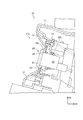
図1は、車両のインストルメントパネル10の一部を示す斜視図である。
インストルメントパネル10は、樹脂製のインストルメントパネル本体11を備えている。インストルメントパネル本体11には、上カバー12と下カバー13とが配置され、上カバー12と下カバー13との間は、図2に示すように、後方に向かうほど間隔が広くなるように形成されている。上カバー12と下カバー13との間には、図示を省略した空調装置に連通する、吹出し部11aが設けられている。吹出し部11aからは、車室内に空調された空気が吹き出される。
吹出し部11aは空気を通過可能なカバー部材16により覆われる。カバー部材16としては、空気が流通可能な板状部材であればよく、パンチングメタルや、金網などの網状の部材を用いることができる。
FIG. 1 is a perspective view showing a part of the
The
The
吹き出し部11aには、それぞれダクト形状の、吹き出し口14および吹き出し口15が設けられる。吹き出し口14および吹き出し口15には、それぞれルーバー14aおよびルーバー15aが配置される。
それぞれダクト形状の、吹き出し口14および吹き出し口15の間には、図2に示すように、スイッチ取り付け部25が配置される。
スイッチ取り付け部25は、インストルメントパネル本体11により仕切られており、吹き出し口14および吹き出し口15から隔絶された空間を有する。スイッチ取り付け部25の内側には、空調した空気は進入しない。
The
As shown in FIG. 2, a
The
スイッチ取り付け部25には、図1に示すように、スイッチ部材(ハザードスイッチ)20が配置される。スイッチ部材20は、車幅方向のほぼ中央部に位置し、運転席および助手席の両方から操作可能である。スイッチ部材20は、図2に示すように、操作部21と、ケース部22とを備える。
ケース部22は、図3に示すように、インストルメントパネル本体11の開口25bに挿入され、開口25bに固定される。
操作部21は、カバー部材16のスイッチ挿入口16aを通して、ケース部22に摺動自在に嵌合される。ケース部22には、スイッチ本体22aが収納される。スイッチ部材20は、操作部21の前端部21aが、ケース部22の内側に押し込まれて、スイッチ本体22aが操作される。
As shown in FIG. 1, a switch member (hazard switch) 20 is arranged on the
As shown in FIG. 3, the
The
操作部21の摺動方向は、カバー部材16の面に直交する。操作部21にはスイッチノブ21bが設けられる。スイッチノブ21bは略四角形状に形成され、スイッチノブ21bの前面に前端部21aが設けられる。
スイッチノブ21bはスイッチ挿入口16aより大きく構成され、スイッチノブ21bの周縁部が、スイッチ挿入口16aの周縁部を覆う。
The sliding direction of the
The
この実施形態によれば、インストルメントパネル10に、上カバー12と下カバー13が存在するため、まず、カバー部材16に視線が誘導され、ついで、カバー部材16より後方に突出するスイッチ部材20に視線が誘導される。従って、スイッチ部材20が容易に認識される。スイッチノブ21bがカバー部材16の上に突出するため、カバー部材16の領域内に独立したスイッチノブ21bが、カバー部材16の上に浮いているように見える。スイッチノブ21bの周縁部が、スイッチ挿入口16aの周縁部を覆うことにより、スイッチ取り付け部25の内部が見えなくなり、インストルメントパネル10の美観性を向上させることができる。
According to this embodiment, since the
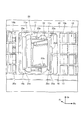
スイッチ取り付け部25は、図4に示すように、吹き出し口14を形成するダクト壁14bと、インストルメントパネル本体11の突部11m、11nと、同じく、それぞれ後方かつ左右外方に延出された側壁部25dと、吹き出し口15を形成するダクト壁15bと、により囲われる。ダクト壁14bおよびダクト壁15bの各後端は、スイッチノブ21bの周縁部にほぼ対向しており、吹き出し口14および吹き出し口15から吹き出される空気が、スイッチノブ21bの周縁部に直接衝突しない構成となっている。
それぞれの側壁部25dには、インストルメントパネル本体11の内外を連通する、上下に配置された排気孔25eが形成されている。各排気孔25eはその一部が、カバー部材16により覆われている。
As shown in FIG. 4, the
インストルメントパネル本体11の突部11m、11nには、それぞれ中間部材25cが設けられる。中間部材25cは、図5に示すように、開口25bと排気孔25eの間に設けられ、ケース部22の挿入口22bよりも図中で上下方向に長く形成される。排気孔25eは、車幅方向において中間部材25cよりも外側に配設される。
図4に示すように、操作部21のスイッチノブ21bの前面には、スイッチノブ21bの前面より、前方に向けて突出して筒状に形成された、第1突起部21cおよび、第2突起21dが形成される。第1突起部21cと第2突起21dの間には空間21eが設けられ、空間21eに中間部材25cが嵌り合う。第1突起部21cは、車幅方向において排気孔25eの外側の端部よりも内側且つ中間部材25cよりも外側に配設される。
また、ケース部22のケース端部22dは、第2突起21dよりも車幅方向内側に位置する。前記第2突起21dは、中間部材25cとケース端部22dの間に位置する。
第1突起部21c、中間部材25c、第2突起21d、ケース端部22dは、ラビリンス状の配列を形成する。ラビリンス状とは、第1突起部21cと、中間部材25cと、第2突起21dと、ケース端部22dと、を重なり合わせ、埃等の侵入物が通る経路をジグザクな経路とする構造である。
As shown in FIG. 4, on the front surface of the
Further, the
The
次に、本実施形態の作用について説明する。
車両の空調装置は、車外もしくは車内より空気を取り込み、熱交換器を介して、吹き出し口14および、吹き出し口15から空気が吹き出す。吹き出された空気の大部分は、カバー部材16を通り車室内に吹き出される。
Next, the operation of this embodiment will be described.
The air conditioner of the vehicle takes in air from the outside or the inside of the vehicle, and blows out the air from the
カバー部材16を通過した空気が、スイッチノブ21bの周縁部に回り込んで、スイッチノブ21bの隙間からケース部22に向けて流れる恐れがある。
本実施形態では、ケース部22に向かった空気は、インストルメントパネル本体11に設けた排気孔25eを介して、インストルメントパネル10の内側に排出され、スイッチ部材20への埃の侵入を低減できる。
インストルメントパネル10の内側は車内と連通し、インストルメントパネル10の内側に排出された空気は車内に戻される。
The air that has passed through the
In the present embodiment, the air directed to the
The inside of the
本実施形態では、吹き出し口14および、吹き出し口15から吹き出した空気が、さらにスイッチ部材20に向かう場合においても、操作部21の形状と、スイッチ取り付け部25の形状により、スイッチ部材20への埃の侵入を低減する。
即ち、第1突起部21cと、中間部材25cと、第2突起21dと、ケース端部22dと、がラビリンス状に配置され、ケース部22内に進入するための経路が長くなり、その経路がジグザクな経路となるため、スイッチ部材20への埃の侵入が低減される。
In the present embodiment, even when the air blown out from the
That is, the
本実施形態のインストルメントパネル10の構造は、空調装置からの空気を車室内に吹き出す吹出し部11aとスイッチ部材20が配設されるスイッチ取り付け部25と、吹出し部11aとスイッチ取り付け部25の一部とを覆い、吹出し部11aからの空気を通過可能なカバー部材16と、スイッチ取り付け部25のうち、カバー部材16に覆われた部分に設けられた排気孔25eと、を備えることを特徴とする。
この構成によれば、カバー部材16の隙間からスイッチ取り付け部25に空調装置からの風と共に埃がスイッチ部材20に向かっても、排気孔25eによりインストルメントパネル10の内部側へ空気が逃げる。
これにより、スイッチ部材20の周りに空気が滞留せず、スイッチ部材20の内部への埃の侵入を低減できる。カバー部材16がスイッチ取り付け部25を覆い、美観性に優れるインストルメントパネル10を提供できる。
The structure of the
According to this configuration, even if dust and wind from the air conditioner enter the
As a result, air does not stay around the
上記構成において、スイッチ部材20は、ケース部22と操作部21と、を備え、操作部21は、カバー部材16を覆っても良い。
この構成によれば、カバー部材16上にスイッチ部材20が配置されるように見え、スイッチ部材20周りの外観上の見栄えが良くなる。
In the above configuration, the
According to this configuration, the
上記構成において、スイッチ取り付け部25は、ケース部22と操作部21との間に中間部材25cを備え、操作部21と中間部材25cとケース部22とによってラビリンス状に配設されても良い。
この構成によれば、ラビリンス状の配置により、スイッチ部材20に進入する埃の量を低減することができる。
In the above configuration, the
According to this configuration, the amount of dust entering the
また、上記構成において、操作部21は第1突起部21cを備え、排気孔25eは、車幅方向において中間部材25cよりも外側に配設され、第1突起部21cは、車幅方向において排気孔25eの外側の端部よりも内側且つ中間部材25cよりも外側に配設されても良い。
この構成によれば、車室内から侵入してきた空気が第1突起部21cにぶつかることで、空気の流れが排気孔25eの方向へと向かうようになるため、効率よく空気をインストルメントパネル10の内側に排出することができる。
Further, in the above configuration, the
According to this configuration, when the air that has entered from the vehicle interior collides with the
また、上記インストルメントパネル構造において、車長方向における前記第1突起部21cの端部は、車長方向における中間部材25cの端部よりも車両前方側に位置しても良い。
この構成によれば、第1突起部21cと中間部材25cとが重なり合っているため、効率良く排気孔25eへ空気を排出しつつ、スイッチ部材20の内部側への空気の侵入を軽減することができる。
Further, in the instrument panel structure, the end portion of the
According to this configuration, since the
また、本実施形態では、車両のインストルメントパネル10の構造が、車室内に空調した空気を吹き出す吹出し部11aと、吹出し部11aを覆う網状のカバー部材16と、カバー部材16により一部が覆われ、吹出し部11aとは隔絶された空間を有するスイッチ取り付け部25と、を備え、スイッチ取り付け部25には、カバー部材16から操作部21を突出させてスイッチ部材20が配設されることを特徴とする。
これにより、スイッチ取り付け部25より車室内に空調した空気が吹き出すことが無く、スイッチ部材20への埃の侵入を低減できる。カバー部材16が吹出し部11aとスイッチ取り付け部25を覆い、美観性に優れるインストルメントパネル10を提供できる。
Further, in the present embodiment, the structure of the
As a result, the air-conditioned air does not blow out from the
上述した各実施形態は、本発明の一態様を示すものに過ぎず、本発明の具体的態様および本発明の適用範囲は上記実施形態に限定されない。例えば、車両内の空調装置操作用のスイッチなどに適用可能である。 Each of the above-described embodiments shows only one aspect of the present invention, and the specific aspects of the present invention and the scope of application of the present invention are not limited to the above-described embodiments. For example, it can be applied to a switch for operating an air conditioner in a vehicle.
10 インストルメントパネル
11 インストルメントパネル本体
14 吹き出し口
15 吹き出し口
16 カバー部材
20 スイッチ部材
21 操作部
21b スイッチノブ
21c 第1突起部
21d 第2突起
22 ケース部
22a スイッチ本体
25 スイッチ取り付け部
25c 中間部材
25d 側壁部
25e 排気孔
10
Claims (6)
スイッチ部材が配設されるスイッチ取り付け部と、
前記吹出し部と前記スイッチ取り付け部の一部とを覆い、前記吹出し部からの前記空気を通過可能なカバー部材と、
前記スイッチ取り付け部のうち、前記カバー部材に覆われた部分に設けられた排気孔と、を備えることを特徴とするインストルメントパネル構造。 A blowout part that blows air from the air conditioner into the passenger compartment,
The switch mounting part where the switch member is arranged and
A cover member that covers the blowout portion and a part of the switch mounting portion and allows the air to pass from the blowout portion.
An instrument panel structure including an exhaust hole provided in a portion of the switch mounting portion covered with the cover member.
前記操作部は、前記カバー部材を覆うことを特徴とする、請求項1に記載のインストルメントパネル構造。 The switch member includes a case portion and an operation portion.
The instrument panel structure according to claim 1, wherein the operating portion covers the cover member.
前記操作部と前記中間部材と前記ケース部とによってラビリンス状に配設されることを特徴とする、請求項2に記載のインストルメントパネル構造。 The switch mounting portion includes an intermediate member between the case portion and the operation portion.
The instrument panel structure according to claim 2, wherein the operation portion, the intermediate member, and the case portion are arranged in a labyrinth shape.
前記排気孔は、車幅方向において前記中間部材よりも外側に配設され、
前記第1突起部は、車幅方向において前記排気孔の外側の端部よりも内側且つ前記中間部材よりも外側に配設されることを特徴とする、請求項3に記載のインストルメントパネル構造。 The operating portion includes a first protrusion and
The exhaust hole is arranged outside the intermediate member in the vehicle width direction.
The instrument panel structure according to claim 3, wherein the first protrusion is arranged inside the outer end of the exhaust hole and outside the intermediate member in the vehicle width direction. ..
車室内に空調した空気を吹き出す吹出し部と、
前記吹出し部を覆う網状のカバー部材と、
前記カバー部材により一部が覆われ、前記吹出し部とは隔絶された空間を有するスイッチ取り付け部と、を備え、
前記スイッチ取り付け部には、前記カバー部材から操作部を突出させてスイッチ部材が配設されている、ことを特徴とするインストルメントパネル構造。 The instrument panel of the vehicle
A blowout part that blows out air-conditioned air into the passenger compartment,
A net-like cover member that covers the blowout portion and
A switch mounting portion that is partially covered with the cover member and has a space isolated from the blowout portion is provided.
An instrument panel structure characterized in that a switch member is disposed on the switch mounting portion by projecting an operation portion from the cover member.
Priority Applications (3)
| Application Number | Priority Date | Filing Date | Title |
|---|---|---|---|
| JP2019061872A JP6873179B2 (en) | 2019-03-27 | 2019-03-27 | Instrument panel structure |
| US16/814,057 US10896792B2 (en) | 2019-03-27 | 2020-03-10 | Instrument panel structure |
| CN202010169145.XA CN111746276B (en) | 2019-03-27 | 2020-03-12 | Instrument board structure |
Applications Claiming Priority (1)
| Application Number | Priority Date | Filing Date | Title |
|---|---|---|---|
| JP2019061872A JP6873179B2 (en) | 2019-03-27 | 2019-03-27 | Instrument panel structure |
Publications (2)
| Publication Number | Publication Date |
|---|---|
| JP2020158038A true JP2020158038A (en) | 2020-10-01 |
| JP6873179B2 JP6873179B2 (en) | 2021-05-19 |
Family
ID=72607951
Family Applications (1)
| Application Number | Title | Priority Date | Filing Date |
|---|---|---|---|
| JP2019061872A Active JP6873179B2 (en) | 2019-03-27 | 2019-03-27 | Instrument panel structure |
Country Status (3)
| Country | Link |
|---|---|
| US (1) | US10896792B2 (en) |
| JP (1) | JP6873179B2 (en) |
| CN (1) | CN111746276B (en) |
Families Citing this family (1)
| Publication number | Priority date | Publication date | Assignee | Title |
|---|---|---|---|---|
| TWI772045B (en) * | 2021-06-01 | 2022-07-21 | 致伸科技股份有限公司 | Keycap and key structure thereof |
Citations (4)
| Publication number | Priority date | Publication date | Assignee | Title |
|---|---|---|---|---|
| JPS52157656U (en) * | 1976-05-26 | 1977-11-30 | ||
| US4287400A (en) * | 1979-11-01 | 1981-09-01 | Timex Corporation | Water-resistant rocker switch |
| JPH0388231U (en) * | 1989-12-26 | 1991-09-10 | ||
| JP2010280344A (en) * | 2009-06-08 | 2010-12-16 | Clarion Co Ltd | Input device of on-vehicle equipment |
Family Cites Families (16)
| Publication number | Priority date | Publication date | Assignee | Title |
|---|---|---|---|---|
| US5516145A (en) * | 1995-06-20 | 1996-05-14 | Chrysler Corporation | Instrument panel assembly |
| US6119060A (en) * | 1997-03-31 | 2000-09-12 | Mazda Motor Corporation | Electronic equipment apparatus and electronic equipment assembly |
| JP3724765B2 (en) * | 1997-11-26 | 2005-12-07 | 富士重工業株式会社 | Instrument panel structure |
| JP2002343193A (en) * | 2001-05-17 | 2002-11-29 | Calsonic Kansei Corp | Operating device for on-board equipment |
| US6881140B2 (en) * | 2003-03-31 | 2005-04-19 | Trw Automotive U.S. Llc | Apparatus for mixing air in a vehicle HVAC system |
| US7264294B2 (en) * | 2005-02-24 | 2007-09-04 | International Automotive Components Group North America, Inc. | Integrated center stack for a motor vehicle |
| JP4837526B2 (en) | 2006-10-27 | 2011-12-14 | 東洋電装株式会社 | Push-button switch |
| US20080202139A1 (en) * | 2007-02-23 | 2008-08-28 | Lear Corporation | Vehicle Environmental Conditioning System and Method |
| JP2009016083A (en) * | 2007-07-02 | 2009-01-22 | Denso Corp | Dial operation device for vehicular air-conditioning |
| JP4645992B2 (en) * | 2008-02-04 | 2011-03-09 | 株式会社ホンダアクセス | Cover panel |
| JP5793441B2 (en) * | 2012-02-08 | 2015-10-14 | 三菱自動車エンジニアリング株式会社 | Mounting structure of air blowing device |
| JP2015044506A (en) * | 2013-08-28 | 2015-03-12 | スズキ株式会社 | Ventilation duct connection structure |
| JP6417188B2 (en) * | 2014-10-31 | 2018-10-31 | ダイキョーニシカワ株式会社 | Vehicle defroster structure |
| CN107584985A (en) * | 2016-07-08 | 2018-01-16 | 福特环球技术公司 | User's request formula climate controlling in vehicle |
| JP2019098878A (en) * | 2017-11-30 | 2019-06-24 | トヨタ自動車株式会社 | register |
| JP7145100B2 (en) * | 2019-02-26 | 2022-09-30 | 東洋電装株式会社 | Vehicle switch device |
-
2019
- 2019-03-27 JP JP2019061872A patent/JP6873179B2/en active Active
-
2020
- 2020-03-10 US US16/814,057 patent/US10896792B2/en active Active
- 2020-03-12 CN CN202010169145.XA patent/CN111746276B/en active Active
Patent Citations (4)
| Publication number | Priority date | Publication date | Assignee | Title |
|---|---|---|---|---|
| JPS52157656U (en) * | 1976-05-26 | 1977-11-30 | ||
| US4287400A (en) * | 1979-11-01 | 1981-09-01 | Timex Corporation | Water-resistant rocker switch |
| JPH0388231U (en) * | 1989-12-26 | 1991-09-10 | ||
| JP2010280344A (en) * | 2009-06-08 | 2010-12-16 | Clarion Co Ltd | Input device of on-vehicle equipment |
Also Published As
| Publication number | Publication date |
|---|---|
| CN111746276A (en) | 2020-10-09 |
| JP6873179B2 (en) | 2021-05-19 |
| CN111746276B (en) | 2023-06-02 |
| US10896792B2 (en) | 2021-01-19 |
| US20200312590A1 (en) | 2020-10-01 |
Similar Documents
| Publication | Publication Date | Title |
|---|---|---|
| US20060186650A1 (en) | Instrument panel for vehicle, having a base which has an open cross section | |
| JP2008247122A (en) | Vehicle body front structure | |
| JP2006193122A (en) | Front part structure of car body | |
| JP6873179B2 (en) | Instrument panel structure | |
| JP6011444B2 (en) | Vehicle front structure | |
| JP2013100037A (en) | Outside mirror | |
| JP4403699B2 (en) | Front body structure of automobile | |
| JP4387719B2 (en) | Air conditioner for vehicles | |
| JP2015085781A (en) | Outside air introduction device for vehicle | |
| JP5070818B2 (en) | Air outlet valve device | |
| JP5403488B2 (en) | Demister duct structure | |
| JP2010006314A (en) | Ventilation structure of automobile | |
| JP3775140B2 (en) | Automotive ventilation structure | |
| JP2006232168A (en) | Instrument panel of vehicle | |
| JPH0410138Y2 (en) | ||
| JP3932837B2 (en) | Cab-over type vehicle cabin ventilation structure | |
| JP2020032984A (en) | Vehicular heat exchanger cooling structure | |
| JP7211035B2 (en) | instrument panel structure | |
| JP6529272B2 (en) | Construction machine defroster | |
| JP6507366B2 (en) | Vehicle ventilation structure | |
| JP6182078B2 (en) | Instrument panel structure | |
| JPH0437008Y2 (en) | ||
| JP6623992B2 (en) | Cowl louver | |
| KR100728728B1 (en) | Air-vent structure in car | |
| JP2005186768A (en) | Construction machine |
Legal Events
| Date | Code | Title | Description |
|---|---|---|---|
| A621 | Written request for application examination |
Free format text: JAPANESE INTERMEDIATE CODE: A621 Effective date: 20191210 |
|
| A977 | Report on retrieval |
Free format text: JAPANESE INTERMEDIATE CODE: A971007 Effective date: 20210125 |
|
| A131 | Notification of reasons for refusal |
Free format text: JAPANESE INTERMEDIATE CODE: A131 Effective date: 20210202 |
|
| A521 | Request for written amendment filed |
Free format text: JAPANESE INTERMEDIATE CODE: A523 Effective date: 20210401 |
|
| TRDD | Decision of grant or rejection written | ||
| A01 | Written decision to grant a patent or to grant a registration (utility model) |
Free format text: JAPANESE INTERMEDIATE CODE: A01 Effective date: 20210413 |
|
| A61 | First payment of annual fees (during grant procedure) |
Free format text: JAPANESE INTERMEDIATE CODE: A61 Effective date: 20210420 |
|
| R150 | Certificate of patent or registration of utility model |
Ref document number: 6873179 Country of ref document: JP Free format text: JAPANESE INTERMEDIATE CODE: R150 |