JP6182078B2 - Instrument panel structure - Google Patents
Instrument panel structure Download PDFInfo
- Publication number
- JP6182078B2 JP6182078B2 JP2014006409A JP2014006409A JP6182078B2 JP 6182078 B2 JP6182078 B2 JP 6182078B2 JP 2014006409 A JP2014006409 A JP 2014006409A JP 2014006409 A JP2014006409 A JP 2014006409A JP 6182078 B2 JP6182078 B2 JP 6182078B2
- Authority
- JP
- Japan
- Prior art keywords
- instrument panel
- width direction
- vehicle width
- vehicle body
- defroster air
- Prior art date
- Legal status (The legal status is an assumption and is not a legal conclusion. Google has not performed a legal analysis and makes no representation as to the accuracy of the status listed.)
- Active
Links
- 239000005357 flat glass Substances 0.000 claims description 44
- 210000000078 claw Anatomy 0.000 description 8
- 238000004378 air conditioning Methods 0.000 description 4
- 239000011347 resin Substances 0.000 description 3
- 229920005989 resin Polymers 0.000 description 3
- 238000007664 blowing Methods 0.000 description 2
- 238000009434 installation Methods 0.000 description 2
- 238000004519 manufacturing process Methods 0.000 description 2
- 238000000034 method Methods 0.000 description 2
- 230000003068 static effect Effects 0.000 description 2
- 230000001143 conditioned effect Effects 0.000 description 1
- 238000007796 conventional method Methods 0.000 description 1
- 238000010257 thawing Methods 0.000 description 1
Images


Description
本発明は、インストルメントパネルと、該インストルメントパネルに設けられると共に、メータユニットの上方を覆う上面部を有するメータフードとを備えているインストルメントパネル構造に関するものである。 The present invention relates to an instrument panel structure including an instrument panel and a meter hood provided on the instrument panel and having an upper surface portion covering the upper side of the meter unit.
インストルメントパネルと、このインストルメントパネルに設けられると共に、メータユニットの上方を覆う上面部を有するメータフードとを備えているインストルメントパネル構造が従来技術として知られている。 An instrument panel structure including an instrument panel and a meter hood provided on the instrument panel and having an upper surface portion covering the upper side of the meter unit is known as a conventional technique.
このインストルメントパネル構造では、フロントウィンドウガラスがインストルメントパネルの車体前方に設けられている。また、メータフードは、インストルメントパネルと一体又は別体に設けられている。 In this instrument panel structure, a front window glass is provided in front of the vehicle body of the instrument panel. The meter hood is provided integrally with or separately from the instrument panel.
ここで、メータフードがインストルメントパネルと別体に設けられている場合、見栄えの点で、メータユニットの背面を覆う必要がある。そこで、例えば、特許文献1に示すものでは、メータフードの前端部がインストルメントパネルと係合されている。
Here, when the meter hood is provided separately from the instrument panel, it is necessary to cover the back surface of the meter unit in terms of appearance. Therefore, for example, in the one shown in
ところで、乗員の前方視界を車体側方に拡大することについて検討すると、この視界拡大という目的を達成するために、フロントピラーを従来よりも車体後方に配置することが考えられる。この場合、ダッシュカウル及びフロントウィンドウガラスは、フロントピラーの後方配置に伴って後方配置される。特に、フロントウィンドウガラスの車幅方向外方側は、フロントピラーに追従して後方配置する必要があり、そのため、フロントウィンドウガラスは、車幅方向外方に行く程、より大きく後方化する。 By the way, considering the enlargement of the front view of the occupant to the side of the vehicle body, it is conceivable to arrange the front pillar at the rear of the vehicle body to achieve the purpose of expanding the view field. In this case, the dash cowl and the front window glass are arranged rearward with the rear arrangement of the front pillar. In particular, the outer side of the front window glass in the vehicle width direction needs to be rearwardly arranged following the front pillar. Therefore, the front window glass is more rearward as it goes outward in the vehicle width direction.
一方で、ステアリング装置の位置は、乗員の着座位置に基づいて決定される。そして、メータユニット及びメータフードの位置は、乗員の上下方向の前方視界やメータユニットの視認性(この視認性は、ステアリング装置の位置の影響を受ける)、メータユニットに対するメータフードの遮光性など、車室側の様々な要因によって制約を受け、このため、メータフードは、大きく後方化することができない。 On the other hand, the position of the steering device is determined based on the seating position of the occupant. The positions of the meter unit and the meter hood are the front view of the occupant in the vertical direction and the visibility of the meter unit (this visibility is affected by the position of the steering device), the light shielding property of the meter hood with respect to the meter unit, etc. Due to various factors on the side of the passenger compartment, the meter hood cannot be greatly rearward.
したがって、フロントウィンドウガラスが大きく後方化した場合であって、インストルメントパネルの車体前後方向長が比較的短いときに、従来のように、メータフードの前端部をインストルメントパネルと係合すると、メータフードの配設に必要な前後スペースが不足して、メータフードがフロントウィンドウガラスと干渉したりする虞がある。 Therefore, when the front window glass is largely rearward and the length of the instrument panel in the longitudinal direction of the vehicle body is relatively short, if the front end of the meter hood is engaged with the instrument panel as in the prior art, the meter There is a risk that the meter hood may interfere with the front window glass due to a lack of front and rear space required for the hood arrangement.
本発明は、かかる点に鑑みてなされたものであり、その課題とするところは、見栄えを損なうことなく、メータフードを車体前後方向長が比較的短いインストルメントパネルに設けることにある。 This invention is made | formed in view of this point, The place made into the subject is providing a meter hood in the instrument panel with a comparatively short vehicle body front-back direction length, without impairing appearance.
上記の課題を解決するため、本発明は、メータユニットの車体前方で且つメータフードにおける上面部の前端部の下方において車幅方向に延びるように縦壁部材が設けられ、この縦壁部材がインストルメントパネルの上面部とメータフードの上面部との間の隙間を覆うことを特徴とする。 In order to solve the above problems, the present invention provides a vertical wall member extending in the vehicle width direction in front of the meter unit and below the front end portion of the upper surface portion of the meter hood. The gap between the upper surface portion of the ment panel and the upper surface portion of the meter hood is covered.
具体的には、本発明は、インストルメントパネルと、該インストルメントパネルに設けられると共に、メータユニットの上方を覆う上面部を有するメータフードとを備えているインストルメントパネル構造を対象とし、次のような解決手段を講じた。 Specifically, the present invention is directed to an instrument panel structure including an instrument panel and a meter hood provided on the instrument panel and having an upper surface portion covering the upper side of the meter unit. The solution was taken.
すなわち、第1の発明は、上記メータフードの上面部の少なくとも一部の、車体前方への延長線は、断面視で上記インストルメントパネルの上面部よりも上方においてフロントウィンドウガラスと交差しており、上記メータフードの上面部の前端部は、上記インストルメントパネルの上面部から上方に間隔をあけて設けられた上方部を有しており、上記メータユニットの車体前方で且つ上記上方部の下方において車幅方向に延びるように設けられ、上記インストルメントパネルの上面部と上記上方部との間の隙間を覆う縦壁部材をさらに備えており、上記インストルメントパネルの前端部は、車体前方に突出するように湾曲しており、上記フロントウィンドウガラスは、上記インストルメントパネルの前端部に沿うように湾曲しており、上記上方部の車幅方向中央部には、車体前方に突出する凸部が形成される一方、該凸部の車幅方向両側には、車体後方に窪む凹部がそれぞれ形成されていることを特徴とするものである。 That is, according to the first aspect of the present invention, at least a part of the upper surface portion of the meter hood, the extension line to the front of the vehicle body intersects the front window glass above the upper surface portion of the instrument panel in a sectional view. The front end portion of the upper surface portion of the meter hood has an upper portion that is spaced upward from the upper surface portion of the instrument panel, and is located in front of the meter unit and below the upper portion. And a vertical wall member that covers the gap between the upper surface portion and the upper portion of the instrument panel, and the front end portion of the instrument panel is located at the front of the vehicle body. Curved so as to protrude, the front window glass is curved along the front end of the instrument panel, In the vehicle width direction central portion of the square portion, while the protrusion protruding to the front of the vehicle body is formed, in the vehicle width direction on both sides of the convex portion, characterized in that the recess which is recessed in the rear of the vehicle body are formed It is what.
これによれば、メータフードの上面部の前端部が、インストルメントパネルの上面部から上方に間隔をあけて設けられた上方部を有しており、縦壁部材が、メータユニットの車体前方で且つ上方部の下方において車幅方向に延びるように設けられ、インストルメントパネルの上面部と上方部との間の隙間を覆うので、メータフードの上面部をインストルメントパネルの上面部まで延長することなく、メータユニットの背面が露出するのを抑制することができる。このため、見栄えを損なうことなく、メータフードを車体前後方向長が比較的短いインストルメントパネルに設けることができる。 According to this, the front end portion of the upper surface portion of the meter hood has an upper portion that is spaced upward from the upper surface portion of the instrument panel, and the vertical wall member is located in front of the meter unit body. And it is provided to extend in the vehicle width direction below the upper part, and covers the gap between the upper part and the upper part of the instrument panel, so that the upper part of the meter hood is extended to the upper part of the instrument panel Without exposing the back surface of the meter unit. Therefore, the meter hood can be provided on the instrument panel having a relatively short length in the longitudinal direction of the vehicle body without impairing the appearance .
また、車体後方に窪む凹部が、上方部における車幅方向中央部の凸部の車幅方向両側にそれぞれ形成されているので、メータフードの上面部をフロントウィンドウガラスよりも車幅方向の湾曲を急にしても、フロントウィンドウガラスに沿って下方に見たときにおける上方部とフロントウィンドウガラスとの間の間隔を狭くすることができる。 In addition , since the concave portion recessed toward the rear of the vehicle body is formed on both sides in the vehicle width direction of the convex portion at the center in the vehicle width direction at the upper part, the upper surface portion of the meter hood is curved in the vehicle width direction more than the front window glass. Even when the distance between the front window glass and the front window glass is reduced, the distance between the upper portion and the front window glass when viewed downward along the front window glass can be reduced.
また、車体前方に突出する凸部が、上方部の車幅方向中央部に形成されている。そして、フロントウィンドウガラスに沿って下方に見たときにおける上方部とフロントウィンドウガラスとの間の間隔を略一定となる状態を維持することができる範囲(すなわち、見栄えを確保することができる範囲)において、凸部を車体前方に且つ下方に延長することができる。このため、インストルメントパネルの上面部と上方部との間の隙間を小さくすることができ、見栄えを良くすることができる。 Moreover, the convex part which protrudes ahead of a vehicle body is formed in the vehicle width direction center part of the upper part. And the range which can maintain the state which becomes substantially constant the space | interval between an upper part and a front window glass when it sees below along a front window glass (namely, range which can ensure appearance). In this case, the convex portion can be extended forward and downward of the vehicle body. For this reason, the clearance gap between the upper surface part and upper part of an instrument panel can be made small, and appearance can be improved.
第2の発明は、上記第1の発明において、上記インストルメントパネルの上面部の前部には、デフロスターエア吹出口が形成されており、上記デフロスターエア吹出口の少なくとも一部は、断面視で上記メータフードの上面部の車体前方への延長線よりも下方に設けられると共に、上記上方部の車体前方に配置されていることを特徴とするものである。 According to a second invention, in the first invention, a defroster air outlet is formed in a front portion of the upper surface portion of the instrument panel, and at least a part of the defroster air outlet is in a cross-sectional view. The meter hood is provided below an extension line of the upper surface portion of the meter hood toward the front of the vehicle body, and is disposed in front of the vehicle body of the upper portion.
ここで、本発明によれば、メータフードの上面部の前端部が、インストルメントパネルの上面部から上方に間隔をあけて設けられており、デフロスターエア吹出口の少なくとも一部が、断面視でメータフードの上面部の車体前方への延長線よりも下方に設けられている。つまり、デフロスターエア吹出口が、インストルメントパネルの上面部におけるフロントウィンドウガラスの下方の前後スペースに設けられている。このように、フロントウィンドウガラスの下方の前後スペースを利用して、デフロスターエア吹出口の配設スペースを確保することができる。 Here, according to the present invention, the front end portion of the upper surface portion of the meter hood is provided to be spaced upward from the upper surface portion of the instrument panel, and at least a part of the defroster air outlet is in a cross-sectional view. The upper surface of the meter hood is provided below the extension line to the front of the vehicle body. That is, the defroster air outlet is provided in the front and rear space below the front window glass on the upper surface portion of the instrument panel. Thus, the space for the defroster air outlet can be secured by using the front and rear space below the front window glass.
また、本発明によれば、デフロスターエア吹出口の少なくとも一部が、上方部の車体前方に配置されているが、縦壁部材が、メータユニットの車体前方で且つ上方部の下方において車幅方向に延びるように設けられ、インストルメントパネルの上面部と上方部との間の隙間を覆うので、縦壁部材によってデフロスターエア吹出口から吹き出したデフロスターエアがメータフード内に侵入するのを抑制することができる。このため、乱流が発生するのを抑制することができると共に、デフロスターエア吹出口から吹き出したデフロスターエアをフロントウィンドウガラスに確実に当てることができる。 Further, according to the present invention, at least a part of the defroster air outlet is disposed in front of the upper body, but the vertical wall member is in the vehicle width direction at the front of the meter unit and below the upper section. Since the vertical wall member covers the gap between the upper portion and the upper portion of the instrument panel, the defroster air blown out from the defroster air outlet is prevented from entering the meter hood. Can do. For this reason, generation | occurrence | production of a turbulent flow can be suppressed, and defroster air blown out from the defroster air blower outlet can be reliably applied to a front window glass.
第3の発明は、上記第2の発明において、上記デフロスターエア吹出口の車幅方向外方端部は、上記凸部の頂点部よりも車幅方向内方に配置されていることを特徴とするものである。 A third invention is characterized in that, in the second invention, an outer end portion in the vehicle width direction of the defroster air outlet is disposed inward in the vehicle width direction from an apex portion of the convex portion. To do.
ところで、従来、デフロスターエア吹出口は、メータフードの前端部とインストルメントパネルとの係合位置よりも車体前方に設けられ、そのため、デフロスト性能は、メータフードの影響を受けなかった。 By the way, conventionally, the defroster air outlet is provided in front of the vehicle body relative to the engagement position between the front end portion of the meter hood and the instrument panel, and therefore the defrost performance is not affected by the meter hood.
しかしながら、本発明のように、インストルメントパネルの車体前後方向長が比較的短い場合であって、メータフードの上面部の前端部が、インストルメントパネルの上面部から上方に間隔をあけて設けられているときに、デフロスト性能の点で、デフロスターエア吹出口の配設スペース確保を考慮する必要がある。 However, as in the present invention, the length of the instrument panel in the longitudinal direction of the vehicle body is relatively short, and the front end portion of the upper surface portion of the meter hood is provided at a distance upward from the upper surface portion of the instrument panel. In view of the defrosting performance, it is necessary to consider securing the installation space for the defroster air outlet.
ここで、本発明によれば、デフロスターエア吹出口の車幅方向外方端部が、凸部の頂点部よりも車幅方向内方に配置されている。つまり、デフロスターエア吹出口の車幅方向外方端部は、凹部のうち車幅方向内方側の凹部に対応する位置に配置されている。このように、車体後方に窪む車幅方向内方側の凹部と、前端部が車体前方に突出するように湾曲するインストルメントパネルとを利用して、デフロスターエア吹出口の配設スペースを確保することができる。 Here, according to this invention, the vehicle width direction outer side edge part of the defroster air blower outlet is arrange | positioned inside the vehicle width direction rather than the vertex part of a convex part. That is, the vehicle width direction outer end portion of the defroster air outlet is disposed at a position corresponding to the concave portion on the vehicle width direction inner side of the concave portion. As described above, the space for the defroster air outlet is secured by using the concave portion on the inner side in the vehicle width direction that is recessed toward the rear of the vehicle body and the instrument panel that is curved so that the front end portion protrudes forward of the vehicle body. can do.
第4の発明は、上記第3の発明において、上記インストルメントパネルの前部には、デフロスターエアダクトが設けられており、上記デフロスターエアダクトは、車幅方向外方に行くに従って上方に傾斜する傾斜部を有していることを特徴とするものである。 In a fourth aspect based on the third aspect , a defroster air duct is provided at a front portion of the instrument panel, and the defroster air duct is inclined so as to be inclined upward as it goes outward in the vehicle width direction. It is characterized by having.
これによれば、デフロスターエア吹出口の車幅方向外方端部が、凸部の頂点部よりも車幅方向内方に配置されているが、デフロスターエアダクトが、車幅方向外方に行くに従って上方に傾斜する傾斜部を有しているので、フロントウィンドウガラスにおけるデフロスターエア吹出口よりも車幅方向外方側の部分(例えば、凸部の頂点部よりも車幅方向外方側の部分)の曇りを晴らすことができる。 According to this, although the vehicle width direction outer side edge part of the defroster air blower outlet is arrange | positioned in the vehicle width direction inner side rather than the vertex part of a convex part, as a defroster air duct goes to a vehicle width direction outer side, Since it has an inclined portion that inclines upward, a portion of the front window glass on the outer side in the vehicle width direction from the defroster air outlet (for example, a portion on the outer side in the vehicle width direction from the apex portion of the projection) The cloudiness can be cleared.
第5の発明は、上記第4の発明において、上記凹部のうち車幅方向外方側の凹部は、平面視で上記デフロスターエア吹出口の車幅方向外方への延長上に配置されると共に、車体正面視で上記傾斜部の車幅方向外方への延長線よりも下方に配置されていることを特徴とするものである。 According to a fifth aspect of the present invention based on the fourth aspect , the concave portion on the outer side in the vehicle width direction among the concave portions is disposed on the extension of the defroster air outlet to the outer side in the vehicle width direction in plan view. In the vehicle body front view, the inclined portion is disposed below the extended line outward in the vehicle width direction.
これによれば、車幅方向外方側の凹部が、平面視でデフロスターエア吹出口の車幅方向外方への延長上に配置されると共に、車体正面視でデフロスターエアダクトの傾斜部の車幅方向外方への延長線よりも下方に配置されているので、デフロスターエア吹出口から吹き出したデフロスターエアが車幅方向外方側の凹部に当たるのを抑制することができる。このため、乱流が発生するのを抑制することができると共に、デフロスターエア吹出口から吹き出したデフロスターエアをフロントウィンドウガラスに確実に当てることができる。 According to this, the concave portion on the outer side in the vehicle width direction is disposed on the extension of the defroster air outlet in the vehicle width direction outward in plan view, and the vehicle width of the inclined portion of the defroster air duct in the front view of the vehicle body Since it is arrange | positioned below rather than the extension line to a direction outward, it can suppress that the defroster air blown out from the defroster air blower outlet hits the recessed part of the vehicle width direction outer side. For this reason, generation | occurrence | production of a turbulent flow can be suppressed, and defroster air blown out from the defroster air blower outlet can be reliably applied to a front window glass.
本発明によれば、メータフードの上面部の前端部が、インストルメントパネルの上面部から上方に間隔をあけて設けられた上方部を有しており、縦壁部材が、メータユニットの車体前方で且つ上方部の下方において車幅方向に延びるように設けられ、インストルメントパネルの上面部と上方部との間の隙間を覆うので、メータフードの上面部をインストルメントパネルの上面部まで延長することなく、メータユニットの背面が露出するのを抑制することができ、このため、見栄えを損なうことなく、メータフードを車体前後方向長が比較的短いインストルメントパネルに設けることができる。 According to the present invention, the front end portion of the upper surface portion of the meter hood has an upper portion that is spaced upward from the upper surface portion of the instrument panel, and the vertical wall member is positioned forward of the meter unit. The upper portion of the meter hood is extended to the upper portion of the instrument panel because the upper portion of the instrument panel covers the gap between the upper portion and the upper portion of the instrument panel. Therefore, it is possible to prevent the back surface of the meter unit from being exposed, and therefore, the meter hood can be provided on the instrument panel having a relatively short length in the longitudinal direction of the vehicle body without impairing the appearance.
以下、本発明の実施形態を図面に基づいて詳細に説明する。以下の好ましい実施形態の説明は、本質的に例示に過ぎず、本発明、その適用物或いはその用途を制限することを意図するものではない。 Hereinafter, embodiments of the present invention will be described in detail with reference to the drawings. The following description of the preferred embodiments is merely exemplary in nature and is not intended to limit the invention, its application, or its use.
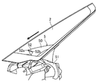
図1は、本発明の実施形態に係るインストルメントパネル構造を示す平面図であり、このインストルメントパネル構造は、車両用インストルメントパネル1(以下、単にインストルメントパネル1という)を備えている。このインストルメントパネル1は樹脂製であって、その前端部は、車体前方に突出するように車幅方向に湾曲状に延びている。
FIG. 1 is a plan view showing an instrument panel structure according to an embodiment of the present invention, and this instrument panel structure includes a vehicle instrument panel 1 (hereinafter simply referred to as an instrument panel 1). The
図1〜図3に示すように、インストルメントパネル1の略水平な上面部10の車体前方端側には、図示しない空調ユニットからのデフロスターエアをフロントウィンドウガラス2に吹き出すフロントデフロスターエア吹出口10aが形成されている。このフロントデフロスターエア吹出口10aは、インストルメントパネル1の車幅方向中央部においてインストルメントパネル1の前端部に沿って車体前方に突出するように車幅方向に湾曲状に延びている。図3及び図4に示すように、フロントデフロスターエア吹出口10aの車幅方向左方端部(本発明の「少なくとも一部」に対応)は、車幅方向の断面視でメータフード5の上面部50の車体前方への延長線(図4に示す二点鎖線を参照)よりも下方に設けられると共に、後述する上方部52の車体前方に配置されている。さらに、図3に示すように、フロントデフロスターエア吹出口10aの車幅方向左方端部(車幅方向外方端部)は、後述する凸部52aの頂点部よりも車幅方向内方に配置されている。図5に示すように、インストルメントパネル1の略垂直な縦壁部11の上端部には、後述する縦壁部材7をインストルメントパネル1に固定するための係合孔11aが3つ(図5では1つのみ図示)形成されている。縦壁部11は、インストルメントパネル1の上面部10の後端部から下方に延びている。
As shown in FIGS. 1 to 3, a front
図1及び図4〜図8に示すように、インストルメントパネル1の上面部10の車体前方には、フロントウィンドウガラス2が設けられており、このフロントウィンドウガラス2は、インストルメントパネル1の前端部に沿って車体前方に突出するように車幅方向に湾曲状に延びている。さらに、フロントウィンドウガラス2は、車体後方に行くに従って上方に傾斜するように略直線状に延びている。
As shown in FIGS. 1 and 4 to 8, a
図7に示すように、インストルメントパネル1の前部には、空調ユニットからのデフロスターエアを通すデフロスターエアダクト3が設けられており、このデフロスターエアダクト3は、インストルメントパネル1の上面部10の下方で且つインストルメントパネル1の縦壁部11の車体前方において車幅方向に延びてフロントデフロスターエア吹出口10aと連通するように配置されている。デフロスターエアダクト3は、車体正面視で略盃状をなしている。さらに、デフロスターエアダクト3の側部は、車幅方向外方に行くに従って上方に略直線状に傾斜する傾斜部30を有している。
As shown in FIG. 7, a
図4、図5及び図7に示すように、インストルメントパネル1の縦壁部11の車体前方には、車体を補強するインストルメントパネルメンバ4が設けられており、このインストルメントパネルメンバ4は車幅方向に延びている。
As shown in FIGS. 4, 5, and 7, an instrument panel member 4 that reinforces the vehicle body is provided in front of the vertical wall portion 11 of the
図1〜図8に示すように、インストルメントパネル1の上部の左半分には、樹脂製のメータフード5が取り付けられており、このメータフード5にスピードメータ等のメータユニット(計器)6が配設される。メータフード5は、上下に2分割されていて、メータユニット6の上方を覆う上面部50と、メータユニット6が配設される計器開口部51aが形成された下側分割体51とを備えている。
As shown in FIGS. 1 to 8, a
図9及び図10にも示すように、メータフード5の上面部50は、上方に突出するように車幅方向に湾曲状に延びる板状部材からなり、車体前方に行くに従って車幅方向に広がっている。メータフード5の上面部50は、フロントウィンドウガラス2よりも車幅方向の湾曲が急である。さらに、メータフード5の上面部50は、車幅方向の断面視で車体前方に行くに従って下方に傾斜するように略直線状に延びている。メータフード5の上面部50の車幅方向中央部(本発明の「少なくとも一部」に対応)の、車体前方への延長線(図5に示す二点鎖線を参照)は、車幅方向の断面視でインストルメントパネル1の上面部10よりも上方においてフロントウィンドウガラス2と交差しており、これは、インストルメントパネル1の上面部10の、車体前後方向長が比較的短いことを意味する。メータフード5の上面部50の前端部は、インストルメントパネル1の上面部10から上方に間隔をあけて設けられた上方部52を有している。つまり、この上方部52は、インストルメントパネル1の上面部10から上方に浮いている。上方部52は、平面視でインストルメントパネル1の上面部10と重なっている。上方部52の車幅方向中央部には、車体前方に突出するように車幅方向に湾曲状に延びる凸部52aが形成される一方、この凸部52aの車幅方向両側には、車体後方に窪むように車幅方向に湾曲状に延びる凹部52bがそれぞれ形成されている。これにより、上方部52の左半分とフロントウィンドウガラス2との間の間隔は、フロントウィンドウガラス2に沿って下方に見たときにおいて略一定となる(図11を参照)。凸部52aは、上方部52の車幅方向両端部よりも車体前方に突出している。凹部52b,52bのうち車幅方向外方側の凹部52bは、平面視でフロントデフロスターエア吹出口10aをインストルメントパネル1の前端部に沿うように車幅方向外方へ延長した延長上(図3に示す二点鎖線を参照)に配置されると共に、車体正面視で傾斜部30の車幅方向外方への延長線(図7に示す二点鎖線を参照)よりも下方に配置されている。さらに、車幅方向外方側の凹部52bは、フロントデフロスターエア吹出口10aとの間の間隔が比較的広い。メータフード5の上面部50の前端部における上方部52の車幅方向両側は、インストルメントパネル1の上面部10と係合している。メータフード5の上面部50の前端部における裏面の車幅方向中央部には、メータフード5を縦壁部材7に固定する際においてメータフード5を縦壁部材7にガイドするためのガイド孔50aが形成される一方、このガイド孔50aの車幅方向両側には、メータフード5を縦壁部材7に固定するための係合孔50bがそれぞれ形成されている(図5及び図10を参照)。
As shown in FIGS. 9 and 10, the
上記下側分割体51は、上方に盛り上がるアーチ状をなす板状部材からなり、その中央部には、車幅方向に延びる上記計器開口部51aが車体前後方向に貫通形成されている。下側分割体51の車幅方向両端部には、空調ユニットからの空調空気を車室に吹き出すエアコン吹出口51bがそれぞれ設けられている。下側分割体51の車幅方向外方端部の上面側には、空調ユニットからのデフロスターエアを図示しないドアウィンドウガラスに吹き出すサイドデフロスターエア吹出口51cが形成されている。下側分割体51の車体前方側面の車幅方向両端部には、メータフード5をインストルメントパネル1に固定するための係合爪51dがそれぞれ複数ずつ形成されている。
The lower divided
図12及び図13に示すように、上記メータユニット6の下端部の車幅方向両端部には、メータユニット6をインストルメントパネル1に固定するための固定部60がそれぞれ設けられており、この固定部60は、インストルメントパネル1の縦壁部11にねじ等の締結部材で止められている。
As shown in FIG.12 and FIG.13, the fixing | fixed
図2、図4、図5、図7、図8、図12及び図13に示すように、メータユニット6の上部の車体前方で且つメータフード5の上方部52の下方には、メータユニット6の車幅方向略全体に亘って車幅方向に延びるように略垂直な板状の縦壁部材7が設けられており、この縦壁部材7は樹脂製であって、インストルメントパネル1の上面部10と上方部52との間の隙間を覆っている。さらに、縦壁部材7は、その上端部がメータユニット6よりも上方に突出するように該縦壁部材7の下部がメータユニット6の背面にねじ等の締結部材で止められている。縦壁部材7の車体前方側面の下端部における車幅方向中央部及び車幅方向両端部には、縦壁部材7をインストルメントパネル1に固定するための係合爪70がそれぞれ形成されている。縦壁部材7の車体後方側面の上端部における車幅方向中央部には、メータフード5を縦壁部材7に固定する際においてメータフード5を縦壁部材7にガイドするためのガイド爪71が形成される一方、その車幅方向両端部には、メータフード5を縦壁部材7に固定するための係合爪72がそれぞれ形成されている。
As shown in FIGS. 2, 4, 5, 7, 8, 12, and 13, the
図1〜図6及び図11に示すように、メータユニット6の車体後方には、ステアリング装置8のステアリングホイール80が設けられている。
As shown in FIGS. 1 to 6 and 11, a
次に、メータフード5、メータユニット6及び縦壁部材7をインストルメントパネル1に取り付ける要領を図14等を参照して説明すると、先ず、縦壁部材7の下部をメータユニット6の背面に締結部材で止める。次に、メータユニット6の固定部60をインストルメントパネル1の縦壁部11に締結部材で止めると共に、縦壁部材7の車体前方側面に設けられた係合爪70を、インストルメントパネル1の縦壁部11の係合孔11aに差し込む。これにより、メータユニット6及び縦壁部材7がインストルメントパネル1の縦壁部11に固定される。次に、メータフード5をインストルメントパネル1及び縦壁部材7に押し付け、この過程で、メータフード5の車体前方側面に設けられた係合爪51dをインストルメントパネル1の図示しない係合孔に挿入係合させると共に、縦壁部材7の車体後方側面に設けられたガイド爪71を、メータフード5のガイド孔50aに挿入案内させながら、縦壁部材7の車体後方側面に設けられた係合爪72を、メータフード5の係合孔50bに挿入係合させる。これにより、メータフード5がインストルメントパネル1及び縦壁部材7に固定される。以上の要領により、メータフード5、メータユニット6及び縦壁部材7がインストルメントパネル1に取り付けられる。
Next, the procedure for attaching the
−効果−
以上より、本実施形態によれば、メータフード5の上面部50の前端部が、インストルメントパネル1の上面部10から上方に間隔をあけて設けられた上方部52を有しており、縦壁部材7が、メータユニット6の車体前方で且つ上方部52の下方において車幅方向に延びるように設けられ、インストルメントパネル1の上面部10と上方部52との間の隙間を覆うので、メータフード5の上面部50をインストルメントパネル1の上面部10まで延長することなく、メータユニット6の背面が露出するのを抑制することができる。このため、見栄えを損なうことなく、メータフード5を車体前後方向長が比較的短いインストルメントパネル1に設けることができる。
-Effect-
As described above, according to the present embodiment, the front end portion of the
また、車体後方に窪む凹部52bが、上方部52における車幅方向中央部の凸部52aの車幅方向両側にそれぞれ形成されているので、メータフード5の上面部50をフロントウィンドウガラス2よりも車幅方向の湾曲を急にしても、フロントウィンドウガラス2に沿って下方に見たときにおける上方部52の左半分とフロントウィンドウガラス2との間の間隔を狭くすることができる。
Moreover, since the recessed
また、車体前方に突出する凸部52aが、上方部52の車幅方向中央部に形成されている。そして、フロントウィンドウガラス2に沿って下方に見たときにおける上方部52の左半分とフロントウィンドウガラス2との間の間隔を略一定となる状態を維持することができる範囲(すなわち、見栄えを確保することができる範囲)において、凸部52aを車体前方に且つ下方に延長することができる。このため、インストルメントパネル1の上面部10と上方部52との間の隙間を小さくすることができ、見栄えを良くすることができる。
Further, a
また、メータフード5の上面部50の前端部が、インストルメントパネル1の上面部10から上方に間隔をあけて設けられており、フロントデフロスターエア吹出口10aの車幅方向左方端部が、車幅方向の断面視でメータフード5の上面部50の車体前方への延長線よりも下方に設けられている。つまり、フロントデフロスターエア吹出口10aが、インストルメントパネル1の上面部10におけるフロントウィンドウガラス2の下方の前後スペースに設けられている。このように、フロントウィンドウガラス2の下方の前後スペースを利用して、フロントデフロスターエア吹出口10aの配設スペースを確保することができる。
Further, the front end portion of the
また、フロントデフロスターエア吹出口10aの車幅方向左方端部が、上方部52の車体前方に配置されているが、縦壁部材7が、メータユニット6の車体前方で且つ上方部52の下方において車幅方向に延びるように設けられ、インストルメントパネル1の上面部10と上方部52との間の隙間を覆うので、縦壁部材7によってフロントデフロスターエア吹出口10aから吹き出したデフロスターエアがメータフード5内に侵入するのを抑制することができる。このため、乱流が発生するのを抑制することができると共に、フロントデフロスターエア吹出口10aから吹き出したデフロスターエアをフロントウィンドウガラス2に確実に当てることができる。
Further, the left end of the front
また、フロントデフロスターエア吹出口10aの車幅方向左方端部が、凸部52aの頂点部よりも車幅方向内方に配置されている。つまり、フロントデフロスターエア吹出口10aの車幅方向左方端部は、凹部52b,52bのうち車幅方向内方側の凹部52bに対応する位置に配置されている。このように、車体後方に窪む車幅方向内方側の凹部52bと、前端部が車体前方に突出するように湾曲するインストルメントパネル1とを利用して、フロントデフロスターエア吹出口10aの配設スペースを確保することができる。
Further, the left end portion in the vehicle width direction of the front
また、フロントデフロスターエア吹出口10aの車幅方向左方端部が、凸部52aの頂点部よりも車幅方向内方に配置されているが、デフロスターエアダクト3の側部が、車幅方向外方に行くに従って上方に傾斜する傾斜部30を有しているので、フロントウィンドウガラス2におけるフロントデフロスターエア吹出口10aよりも車幅方向外方側の部分(具体的に、凸部52aの頂点部よりも車幅方向外方側の部分)の曇りを晴らすことができる。
Further, the left end portion in the vehicle width direction of the front
また、車幅方向外方側の凹部52bが、平面視でフロントデフロスターエア吹出口10aの車幅方向外方への延長上に配置されると共に、車体正面視でデフロスターエアダクト3の傾斜部30の車幅方向外方への延長線よりも下方に配置されているので、フロントデフロスターエア吹出口10aから吹き出したデフロスターエアが車幅方向外方側の凹部52bに当たるのを抑制することができる。このため、乱流が発生するのを抑制することができると共に、フロントデフロスターエア吹出口10aから吹き出したデフロスターエアをフロントウィンドウガラス2に確実に当てることができる。
Further, the
(その他の実施形態)
上記実施形態では、メータフード5を上面部50及び下側分割体51で構成したが、これに限らず、例えば、上面部50のみで構成してもよい。
(Other embodiments)
In the above-described embodiment, the
また、上記実施形態では、メータフード5の上面部50の車幅方向中央部の、車体前方への延長線を、車幅方向の断面視でインストルメントパネル1の上面部10よりも上方においてフロントウィンドウガラス2と交差させたが、これに限らず、例えば、メータフード5の上面部50の車幅方向全体の、車体前方への延長線を、車幅方向の断面視でインストルメントパネル1の上面部10よりも上方においてフロントウィンドウガラス2と交差させても良い。
Further, in the above-described embodiment, the front-side extension line of the vehicle width direction center portion of the
また、上記実施形態では、フロントデフロスターエア吹出口10aの車幅方向左方端部を、車幅方向の断面視でメータフード5の上面部50の車体前方への延長線よりも下方に設けると共に、上方部52の車体前方に配置したが、これに限らず、例えば、フロントデフロスターエア吹出口10aの車幅方向全体を、車幅方向の断面視でメータフード5の上面部50の車体前方への延長線よりも下方に設けると共に、上方部52の車体前方に配置してもよい。
Moreover, in the said embodiment, while providing the vehicle width direction left end part of the front defroster
また、上記実施形態では、縦壁部材7をメータユニット6と一体化したが、これらを一体化しなくてもよい。
Moreover, in the said embodiment, although the
また、上記実施形態では、メータフード5をインストルメントパネル1の左半分に設けたが、これに限らず、例えば、インストルメントパネル1の右半分に設けてもよいし、車幅方向中央部に設けてもよい。
Moreover, in the said embodiment, although the
また、上記実施形態では、フロントデフロスターエア吹出口10aをインストルメントパネル1の上面部10の車幅方向中央部に形成したが、これに限らず、例えば、図15に示すように、インストルメントパネル1の上面部10の車幅方向両端近傍まで延びるように形成してもよい。この場合、フロントデフロスターエア吹出口10aの車幅方向左方端部は、メータフード5の上方部52よりも車幅方向外方に配置される。この構成は、例えば、特開昭62−166145号公報に示すように、空調装置が、デフロスターエアダクトに静圧チャンバを設けた所謂「静圧タイプ」のものの場合に適用される。なお、上記実施形態の空調装置は、所謂「動圧タイプ」のものである。
Moreover, in the said embodiment, although the front defroster
以上説明したように、本発明に係るインストルメントパネル構造は、見栄えを損なうことなく、メータフードを車体前後方向長が比較的短いインストルメントパネルに設けることが必要な用途等に適用することができる。 As described above, the instrument panel structure according to the present invention can be applied to uses and the like that require the meter hood to be provided on an instrument panel having a relatively short longitudinal length in the vehicle body without impairing the appearance. .
1 インストルメントパネル
10 上面部
10a フロントデフロスターエア吹出口
2 フロントウィンドウガラス
3 デフロスターエアダクト
30 傾斜部
5 メータフード
50 上面部
52 上方部
52a 凸部
52b 凹部
6 メータユニット
7 縦壁部材
DESCRIPTION OF
52a Convex
Claims (5)
上記メータフードの上面部の少なくとも一部の、車体前方への延長線は、断面視で上記インストルメントパネルの上面部よりも上方においてフロントウィンドウガラスと交差しており、
上記メータフードの上面部の前端部は、上記インストルメントパネルの上面部から上方に間隔をあけて設けられた上方部を有しており、
上記メータユニットの車体前方で且つ上記上方部の下方において車幅方向に延びるように設けられ、上記インストルメントパネルの上面部と上記上方部との間の隙間を覆う縦壁部材をさらに備えており、
上記インストルメントパネルの前端部は、車体前方に突出するように湾曲しており、
上記フロントウィンドウガラスは、上記インストルメントパネルの前端部に沿うように湾曲しており、
上記上方部の車幅方向中央部には、車体前方に突出する凸部が形成される一方、該凸部の車幅方向両側には、車体後方に窪む凹部がそれぞれ形成されていることを特徴とするインストルメントパネル構造。 An instrument panel structure provided with an instrument panel and a meter hood provided on the instrument panel and having an upper surface portion covering the top of the meter unit,
An extension line of at least a part of the upper surface portion of the meter hood to the front of the vehicle body intersects the front window glass above the upper surface portion of the instrument panel in a sectional view,
The front end portion of the upper surface portion of the meter hood has an upper portion provided at a distance from the upper surface portion of the instrument panel.
It provided so as to extend in the vehicle width direction at and below the upper portion in the vehicle body front of the meter unit further includes a vertical wall member covering the gap between the top portion and the upper portion of the instrument panel ,
The front end of the instrument panel is curved so as to protrude forward of the vehicle body,
The front window glass is curved along the front end of the instrument panel,
A convex portion that protrudes forward of the vehicle body is formed in the vehicle width direction central portion of the upper portion, and a concave portion that is recessed toward the rear of the vehicle body is formed on both sides of the convex portion in the vehicle width direction. Characteristic instrument panel structure.
上記インストルメントパネルの上面部の前部には、デフロスターエア吹出口が形成されており、
上記デフロスターエア吹出口の少なくとも一部は、断面視で上記メータフードの上面部の車体前方への延長線よりも下方に設けられると共に、上記上方部の車体前方に配置されていることを特徴とするインストルメントパネル構造。 In the instrument panel structure according to claim 1 ,
In the front part of the upper surface of the instrument panel, a defroster air outlet is formed,
At least a part of the defroster air outlet is provided below an extension line of the upper surface portion of the meter hood in front of the vehicle body in a cross-sectional view, and is disposed in front of the vehicle body in the upper portion. Instrument panel structure.
上記デフロスターエア吹出口の車幅方向外方端部は、上記凸部の頂点部よりも車幅方向内方に配置されていることを特徴とするインストルメントパネル構造。 In the instrument panel structure according to claim 2 ,
An instrument panel structure, wherein an outer end in the vehicle width direction of the defroster air outlet is disposed inward in the vehicle width direction from the apex of the convex portion.
上記インストルメントパネルの前部には、デフロスターエアダクトが設けられており、
上記デフロスターエアダクトは、車幅方向外方に行くに従って上方に傾斜する傾斜部を有していることを特徴とするインストルメントパネル構造。 In the instrument panel structure according to claim 3 ,
A defroster air duct is provided at the front of the instrument panel,
The instrument panel structure according to claim 1, wherein the defroster air duct has an inclined portion that is inclined upward as it goes outward in the vehicle width direction.
上記凹部のうち車幅方向外方側の凹部は、平面視で上記デフロスターエア吹出口の車幅方向外方への延長上に配置されると共に、車体正面視で上記傾斜部の車幅方向外方への延長線よりも下方に配置されていることを特徴とするインストルメントパネル構造。 In the instrument panel structure according to claim 4 ,
A concave portion on the outer side in the vehicle width direction of the concave portion is arranged on the extension of the defroster air outlet to the outer side in the vehicle width direction in a plan view, and outside the inclined portion in the vehicle width direction in a front view of the vehicle body. Instrument panel structure characterized by being arranged below the extension line toward the direction.
Priority Applications (1)
| Application Number | Priority Date | Filing Date | Title |
|---|---|---|---|
| JP2014006409A JP6182078B2 (en) | 2014-01-17 | 2014-01-17 | Instrument panel structure |
Applications Claiming Priority (1)
| Application Number | Priority Date | Filing Date | Title |
|---|---|---|---|
| JP2014006409A JP6182078B2 (en) | 2014-01-17 | 2014-01-17 | Instrument panel structure |
Publications (2)
| Publication Number | Publication Date |
|---|---|
| JP2015134542A JP2015134542A (en) | 2015-07-27 |
| JP6182078B2 true JP6182078B2 (en) | 2017-08-16 |
Family
ID=53766757
Family Applications (1)
| Application Number | Title | Priority Date | Filing Date |
|---|---|---|---|
| JP2014006409A Active JP6182078B2 (en) | 2014-01-17 | 2014-01-17 | Instrument panel structure |
Country Status (1)
| Country | Link |
|---|---|
| JP (1) | JP6182078B2 (en) |
Family Cites Families (8)
| Publication number | Priority date | Publication date | Assignee | Title |
|---|---|---|---|---|
| US3276813A (en) * | 1964-07-14 | 1966-10-04 | Pittsburgh Plate Glass Co | Glare shielding and instrument viewing arrangement |
| JPH062826Y2 (en) * | 1987-03-31 | 1994-01-26 | 日野自動車工業株式会社 | Additional instrument for automobile |
| JPH0712148Y2 (en) * | 1988-02-03 | 1995-03-22 | 日産車体株式会社 | Instrument panel structure |
| JPH0260030U (en) * | 1988-10-26 | 1990-05-02 | ||
| JP3855867B2 (en) * | 2002-07-10 | 2006-12-13 | 日産自動車株式会社 | Interior parts for vehicles |
| ES1056795Y (en) * | 2004-01-30 | 2004-09-01 | Seat Sa | FRONT BOARD FOR MOTOR VEHICLES. |
| JP2005239097A (en) * | 2004-03-01 | 2005-09-08 | Calsonic Kansei Corp | Instrument device structure for vehicle |
| JP5260398B2 (en) * | 2009-04-23 | 2013-08-14 | 日野自動車株式会社 | Camera arrangement structure |
-
2014
- 2014-01-17 JP JP2014006409A patent/JP6182078B2/en active Active
Also Published As
| Publication number | Publication date |
|---|---|
| JP2015134542A (en) | 2015-07-27 |
Similar Documents
| Publication | Publication Date | Title |
|---|---|---|
| JP5601018B2 (en) | Vehicle cowl structure | |
| JP6241463B2 (en) | Cowl structure | |
| JP5314305B2 (en) | Car front pillar trim mounting structure | |
| CN108016505B (en) | Vehicle body front structure | |
| JP2008126973A (en) | Vehicular head up display section structure | |
| JP6182078B2 (en) | Instrument panel structure | |
| JP2015085781A (en) | Outside air introduction device for vehicle | |
| CN111746276B (en) | Instrument board structure | |
| JP6182089B2 (en) | Instrument panel structure | |
| KR102596241B1 (en) | Cowl assembly of vehicle | |
| JP6508180B2 (en) | Front body structure | |
| JP6623499B2 (en) | Vehicle air-conditioning outlet structure | |
| JP2013252800A (en) | Mounting structure of instrument panel | |
| JP5621161B2 (en) | Air outlet structure for vehicle air conditioner | |
| JP6052021B2 (en) | Duct structure | |
| JP2017193269A (en) | Vehicular air conditioning blowout part structure | |
| JP6883452B2 (en) | Vehicle air blower | |
| KR20120003956U (en) | two way side mirror | |
| JP2006176070A (en) | Cowl louver | |
| JP4654576B2 (en) | Automotive bumper structure | |
| JP2010006314A (en) | Ventilation structure of automobile | |
| JP6358130B2 (en) | Vehicle waterproof structure | |
| JP7211035B2 (en) | instrument panel structure | |
| JP6623992B2 (en) | Cowl louver | |
| JP7320905B2 (en) | Floor cover for in-vehicle wiring harness and protection structure for in-vehicle wiring harness |
Legal Events
| Date | Code | Title | Description |
|---|---|---|---|
| A621 | Written request for application examination |
Free format text: JAPANESE INTERMEDIATE CODE: A621 Effective date: 20160823 |
|
| A977 | Report on retrieval |
Free format text: JAPANESE INTERMEDIATE CODE: A971007 Effective date: 20170413 |
|
| A131 | Notification of reasons for refusal |
Free format text: JAPANESE INTERMEDIATE CODE: A131 Effective date: 20170418 |
|
| A521 | Request for written amendment filed |
Free format text: JAPANESE INTERMEDIATE CODE: A523 Effective date: 20170613 |
|
| TRDD | Decision of grant or rejection written | ||
| A01 | Written decision to grant a patent or to grant a registration (utility model) |
Free format text: JAPANESE INTERMEDIATE CODE: A01 Effective date: 20170704 |
|
| A61 | First payment of annual fees (during grant procedure) |
Free format text: JAPANESE INTERMEDIATE CODE: A61 Effective date: 20170721 |
|
| R150 | Certificate of patent or registration of utility model |
Ref document number: 6182078 Country of ref document: JP Free format text: JAPANESE INTERMEDIATE CODE: R150 |
|
| R250 | Receipt of annual fees |
Free format text: JAPANESE INTERMEDIATE CODE: R250 |
|
| R250 | Receipt of annual fees |
Free format text: JAPANESE INTERMEDIATE CODE: R250 |
|
| R250 | Receipt of annual fees |
Free format text: JAPANESE INTERMEDIATE CODE: R250 |
|
| R250 | Receipt of annual fees |
Free format text: JAPANESE INTERMEDIATE CODE: R250 |